EP2633908B1 - Biomaterial detecting device - Google Patents
Biomaterial detecting device Download PDFInfo
- Publication number
- EP2633908B1 EP2633908B1 EP12175714.0A EP12175714A EP2633908B1 EP 2633908 B1 EP2633908 B1 EP 2633908B1 EP 12175714 A EP12175714 A EP 12175714A EP 2633908 B1 EP2633908 B1 EP 2633908B1
- Authority
- EP
- European Patent Office
- Prior art keywords
- tube
- detecting device
- biomaterial
- rod
- tube coupler
- Prior art date
- Legal status (The legal status is an assumption and is not a legal conclusion. Google has not performed a legal analysis and makes no representation as to the accuracy of the status listed.)
- Not-in-force
Links
Images





Classifications
-
- B—PERFORMING OPERATIONS; TRANSPORTING
- B01—PHYSICAL OR CHEMICAL PROCESSES OR APPARATUS IN GENERAL
- B01L—CHEMICAL OR PHYSICAL LABORATORY APPARATUS FOR GENERAL USE
- B01L3/00—Containers or dishes for laboratory use, e.g. laboratory glassware; Droppers
- B01L3/50—Containers for the purpose of retaining a material to be analysed, e.g. test tubes
- B01L3/508—Rigid containers without fluid transport within
- B01L3/5085—Rigid containers without fluid transport within for multiple samples, e.g. microtitration plates
- B01L3/50853—Rigid containers without fluid transport within for multiple samples, e.g. microtitration plates with covers or lids
-
- B—PERFORMING OPERATIONS; TRANSPORTING
- B01—PHYSICAL OR CHEMICAL PROCESSES OR APPARATUS IN GENERAL
- B01L—CHEMICAL OR PHYSICAL LABORATORY APPARATUS FOR GENERAL USE
- B01L3/00—Containers or dishes for laboratory use, e.g. laboratory glassware; Droppers
- B01L3/50—Containers for the purpose of retaining a material to be analysed, e.g. test tubes
- B01L3/508—Rigid containers without fluid transport within
- B01L3/5082—Test tubes per se
- B01L3/50825—Closing or opening means, corks, bungs
-
- C—CHEMISTRY; METALLURGY
- C12—BIOCHEMISTRY; BEER; SPIRITS; WINE; VINEGAR; MICROBIOLOGY; ENZYMOLOGY; MUTATION OR GENETIC ENGINEERING
- C12Q—MEASURING OR TESTING PROCESSES INVOLVING ENZYMES, NUCLEIC ACIDS OR MICROORGANISMS; COMPOSITIONS OR TEST PAPERS THEREFOR; PROCESSES OF PREPARING SUCH COMPOSITIONS; CONDITION-RESPONSIVE CONTROL IN MICROBIOLOGICAL OR ENZYMOLOGICAL PROCESSES
- C12Q1/00—Measuring or testing processes involving enzymes, nucleic acids or microorganisms; Compositions therefor; Processes of preparing such compositions
- C12Q1/68—Measuring or testing processes involving enzymes, nucleic acids or microorganisms; Compositions therefor; Processes of preparing such compositions involving nucleic acids
- C12Q1/6813—Hybridisation assays
- C12Q1/6816—Hybridisation assays characterised by the detection means
-
- B—PERFORMING OPERATIONS; TRANSPORTING
- B01—PHYSICAL OR CHEMICAL PROCESSES OR APPARATUS IN GENERAL
- B01L—CHEMICAL OR PHYSICAL LABORATORY APPARATUS FOR GENERAL USE
- B01L2200/00—Solutions for specific problems relating to chemical or physical laboratory apparatus
- B01L2200/02—Adapting objects or devices to another
- B01L2200/025—Align devices or objects to ensure defined positions relative to each other
-
- B—PERFORMING OPERATIONS; TRANSPORTING
- B01—PHYSICAL OR CHEMICAL PROCESSES OR APPARATUS IN GENERAL
- B01L—CHEMICAL OR PHYSICAL LABORATORY APPARATUS FOR GENERAL USE
- B01L2300/00—Additional constructional details
- B01L2300/04—Closures and closing means
- B01L2300/046—Function or devices integrated in the closure
-
- B—PERFORMING OPERATIONS; TRANSPORTING
- B01—PHYSICAL OR CHEMICAL PROCESSES OR APPARATUS IN GENERAL
- B01L—CHEMICAL OR PHYSICAL LABORATORY APPARATUS FOR GENERAL USE
- B01L2300/00—Additional constructional details
- B01L2300/06—Auxiliary integrated devices, integrated components
- B01L2300/0609—Holders integrated in container to position an object
-
- B—PERFORMING OPERATIONS; TRANSPORTING
- B01—PHYSICAL OR CHEMICAL PROCESSES OR APPARATUS IN GENERAL
- B01L—CHEMICAL OR PHYSICAL LABORATORY APPARATUS FOR GENERAL USE
- B01L2300/00—Additional constructional details
- B01L2300/06—Auxiliary integrated devices, integrated components
- B01L2300/0627—Sensor or part of a sensor is integrated
- B01L2300/0636—Integrated biosensor, microarrays
Definitions
- the following disclosure relates to a biomaterial detecting device for confirming or detecting a biomaterial reaction, and more particularly to a biomaterial detecting device, capable of facilitating confirmation and detection of a biomaterial by being coupled with a tube containing a biomaterial solution to be tested such that a detector is immersed in the biomaterial solution, to thereby induce a reaction between the biomaterial and the detector, and capable of improving reliability in analysis by having a cap structure to thereby prevent evaporation of a sample and infiltration of an external material at the time of a biomaterial reaction in the tube.
- DNA microarray DNA chip
- DNA chip DNA microarray
- This technology is realized by immobilizing a nucleic acid probe, an antibody, or the like, on various solid surfaces such as a glass substrate, a metal substrate, a bead, a plastic, and the like, and has been employed for performing medical diagnosis in hospitals or clinics since many different targets can be simultaneously analyzed.
- a chamber called a frame seal is formed on a flat slide glass, and a solution is put thereinto, so that a bioreaction is allowed to proceed.
- the seal needs to be torn and washed. Therefore, this work may require a large amount of labor and skilled workers and moreover be cumbersome.
- a multi-well plate where a plurality of wells (containing spaces) is formed in a plate shape such that samples are contained therein for reaction with biomaterials is sometimes used.
- a small amount of sample from the solution containing biomaterials which is contained in a reaction container such as a tube or the like, is injected into the well from the solution by using a pipette or the like, and then the biomaterial reaction is allowed to occur by using a DNA chip.
- the samples are evaporated at the time of heating for reaction of the samples, which may have a large effect on the results of the biomaterial reaction, and thus, reliability in analysis may be deteriorated.
- Korean Laid-Open Publication KR 10-2006-0060069 A discloses an apparatus for minimizing evaporation or condensation of samples in tubes of a multi-well plate, installed in a heat circulator for PCR.
- US 6,197,597 B1 discloses a device for immunodetermination, which comprises a rod having at its lower end a solid-phase body to be immersed into a well containing a fluid and on its upper end a handle to be grasped by robotics for exact control of its horizontal and vertical position.
- US 2004/258563 A1 discloses a biomaterial detection device comprising a head, a tube coupler protruded downwardly from the head; a rod extended downwardly from the tube coupler; and a detector which is formed at a lower side of the rod.
- An embodiment of the present invention is directed to providing a biomaterial detecting device, capable of obviating inconveniences arising from injecting a sample into the existing well or frame seal, and automating a series of procedures such as injection of the sample, reaction with a biomaterial, detection of results, and analysis of results.
- Another embodiment of the present invention is directed to providing a biomaterial detecting device capable of, in the case of a gene amplification reaction, preventing the sample from being evaporated at the time of heating for reaction of the sample, to thereby improve reliability in analysis of a biomaterial reaction.
- a biomaterial detecting device including: a head; a tube coupler protruded downwardly from the head and being configured to be inserted into and coupled with a tube containing a sample of biomaterial; a rod extended downwardly from the tube coupler; a detector formed at a lower side of the rod; and a direction indicator for confirming a direction of the biomaterial detecting device, wherein the detector includes materials arrayed on a lower surface thereof, the materials being selected from the group consisting of protein, nucleic acid, peptide nucleic acid (PNA), aptamer and antibody, and the direction indicator is formed on one side of a lower surface of the tube coupler.
- PNA peptide nucleic acid
- the rod may be detachable from the tube coupler.
- the tube coupler may have protrusions formed on an outer circumferential surface thereof.
- the head may have an adaptor formed thereon.
- an upper portion may have a larger diameter than a lower portion.
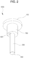
- FIGS. 2 and 3 are a perspective view and a front view showing a first embodiment of a biomaterial detecting device of the present invention.
- a biomaterial detecting device 1000 of the present invention includes: a head 100; a tube coupler 200 protruded downwardly from the head 100; a rod 300 extended downwardly from the tube coupler 200; and a detector 400 formed at a lower side of the rod 300.
- the head 100 may be formed in a flat plate shape, a block shape, or the like.
- the biomaterial detecting device 1000 is manually transferred by a hand of the user or coupled with or decoupled from the tube (reaction container) containing the sample, the head may receive a force applied thereto or may be combined with an automated device to be movable.
- the tube coupler 200 is protruded downwardly from the head 100, and the tube may be outwardly inserted into and coupled with the tube coupler 200.
- a groove is formed in an outer circumferential surface of the tube coupler 200 along a circumferential direction thereof, and an elastic sealing member such as an O-ring is combined with the groove, so that an inside of the tube can be sealed when the tube is inserted into and coupled with the tube coupler 200.
- the rod 300 is extended downwardly from the tube coupler 200, and may be lengthily formed in a stick shape along a lower direction thereof.
- the rod 300 preferably has a smaller diameter than the tube coupler 200. Since the rod 300 is contacted with the sample such as a biomaterial solution, the rod 300 is preferably formed of glass having no reactivity with the sample.
- the rod 300 may be detachable from the tube coupler 200. That is, a hole is formed in a lower portion of the tube coupler 200, and the rod 300 is inserted into the hole and coupled with the tube coupler 200. Thus, the rod 300 may be replaced, as necessary.
- the detector 400 is formed at the lower side of the rod 300.
- the detector 400 is immersed in the sample, to thereby react with the sample, and thus, can detect a target material.
- materials selected from the group consisting of protein, nucleic acid, peptide nucleic acid (PNA), aptamer, and antibody are arrayed (arranged) on the lower surface of the detector 400. That is, the target gene probes may be arrayed so as to detect the biomaterial, such that they are immobilized to have particular directivity.
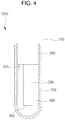
- the biomaterial detecting device 1000 of the present invention includes the head 100, the tube coupler 200, the rod 300, and the detector 400, and the tube coupler 200 may be inserted into and coupled with the tube 700 containing the sample, as shown in FIG. 4 .
- the detector 400 formed at the lower side of the rod 300 is immersed in the sample 800 in the tube 700.
- gene application and hybridization may be allowed to proceed in the tube 700, and simultaneously, the amplified gene may react with the target gene probes of the detector 400 during the hybridization procedure, to thereby induce conjugation and reaction with the target gene probes.
- the real-time polymerase chain reaction (PCR, gene amplification) is allowed to proceed in the tube 700, and a fluorescent signal generated in the tube 700 is acquired in real-time by using a monitoring apparatus. After that, the hybridization is allowed to proceed, and the rod 300 and the detector 400 are separated from the tube 700, and then washed. Then a fluorescent signal reacting with the probe is obtained by using an exclusive fluorescent detector, and then the DNA chip (detector) analysis may be carried out. Therefore, the real-time PCR and the DNA chip analysis can be integratedly carried out in one tube.
- PCR polymerase chain reaction
- the biomaterial detecting device is coupled with the reaction container (tube) containing the sample in a cap type while the detector formed at the end portion of the rod is immersed in the sample therein, so that the biomaterial reaction can be easily detected, thereby obviating the cumbersomeness of transferring the amplified gene, preventing contamination due to external factors generable during this procedure, and automating a series of procedures such as injection of the sample, reaction of the biomaterial, and detection of results.
- the sample in the case of gene amplification reaction, can be prevented from being evaporated at the time of heating for reaction of the sample, thereby improving reliability in analysis of the biomaterial reaction.
- protrusions 210 may be formed on an outer circumferential surface of the tube coupler 200.
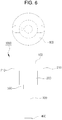
- the protrusions 210 may be formed at both sides of the tube coupler 200 below the head 100. The reason is that, when the tube 700 is outwardly inserted into the tube coupler 200, the upper side of the tube 700 is caught by the protrusions 20 to thereby not be further inserted into the tube coupler 200, so that the head 100 is spaced apart from the tube 700 by a predetermined height (h) to thereby form a space, as shown in FIG. 7 . That is, the space is generated between the tube 700 and the head 100 by the protrusions 210, and thus, this space allows the tube 700 and the head 100 to be easily separated from each other while they are held with both hands.
- h predetermined height
- the protrusions 210 may be formed in various shapes, at various positions, and in various numbers.
- the protrusions 210 may be formed at both sides of the tube coupler 200 as described above, or may be protruded from only one side of the tube coupler 200. Also, the protrusions 210 may be spaced apart from the lower surface of the head 100 at a predetermined distance.
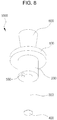
- an adaptor 600 may be extended from an upper side of the head 100, as shown in FIGS. 8 and 9 .
- the biomaterial detecting device 1000 of the present invention can be easily moved and detached from the tube 700 by using an automating equipment.
- the biomaterial detecting device 100 of the present invention can be easily coupled with the tube 700, decoupled therefrom after reaction, washed after being transferred, and transferred to a monitoring device for detection, and used for other procedures.
- an upper portion thereof may have a larger diameter than a lower portion thereof. Therefore, in the case where the adaptor 600 is inserted into and combined with a mounting portion of the automation equipment, since the diameter of the upper side of the adaptor 600 is large, separation of the adaptor 600 can be prevented while the biomaterial detecting device 1000 is decoupled from the tube 700.
- the adaptor 600 may be inclined outwardly and upwardly, or an upper portion of the adaptor 600 may have a large diameter to thereby form a step protrusion.
- an inside of the adaptor 600 may be hollow, such that, the mounting portion of the automation equipment is inserted into and coupled with the hollowed portion of the adaptor 600.
- the biomaterial detecting device 1000 has a direction indicator 500 for confirming a direction. Since the target gene probes is arrayed and immobilized to have a particular directivity such that the materials are arrayed (arranged) on the lower surface of the detector 400 to thereby detect the biomaterial, the materials being selected from protein, nucleic acid, peptide nucleic acid (PNA), aptamer, and antibody, the direction indicator 500 is formed to confirm a direction of the biomaterial detecting device 1000.
- PNA peptide nucleic acid
- the direction indicator 500 is formed on one side of the lower surface of the tube coupler 200 such that it is protruded to a space where the coupling with the tube 700 is not interfered.
- biomaterial detecting device of the present invention may be variously applied in various experiment fields below due to the above advantages.
- the biomaterial detecting device is coupled with the reaction container (tube) containing a sample in a cap form while the detector formed at an end of the rod is immersed in the sample therein, thereby facilitating detection of the biomaterial reaction and automating a series of procedures such as injection of the sample, reaction with the biomaterial, detection of results, and analysis of results.
- the biomaterial detecting device of the present invention in the case of gene amplification reaction, can prevent the sample from being evaporated at the time of heating for reaction of the sample, thereby improving reliability in analysis of the biomaterial reaction.
- the present invention is not limited to the above-mentioned embodiments and an applied range thereof may be various.
Landscapes
- Chemical & Material Sciences (AREA)
- Health & Medical Sciences (AREA)
- Analytical Chemistry (AREA)
- General Health & Medical Sciences (AREA)
- Hematology (AREA)
- Clinical Laboratory Science (AREA)
- Chemical Kinetics & Catalysis (AREA)
- Organic Chemistry (AREA)
- Life Sciences & Earth Sciences (AREA)
- Zoology (AREA)
- Proteomics, Peptides & Aminoacids (AREA)
- Engineering & Computer Science (AREA)
- Wood Science & Technology (AREA)
- Biophysics (AREA)
- Microbiology (AREA)
- Molecular Biology (AREA)
- Immunology (AREA)
- Biotechnology (AREA)
- Physics & Mathematics (AREA)
- Biochemistry (AREA)
- Bioinformatics & Cheminformatics (AREA)
- General Engineering & Computer Science (AREA)
- Genetics & Genomics (AREA)
- Apparatus Associated With Microorganisms And Enzymes (AREA)
- Investigating Or Analysing Biological Materials (AREA)
Description
- The following disclosure relates to a biomaterial detecting device for confirming or detecting a biomaterial reaction, and more particularly to a biomaterial detecting device, capable of facilitating confirmation and detection of a biomaterial by being coupled with a tube containing a biomaterial solution to be tested such that a detector is immersed in the biomaterial solution, to thereby induce a reaction between the biomaterial and the detector, and capable of improving reliability in analysis by having a cap structure to thereby prevent evaporation of a sample and infiltration of an external material at the time of a biomaterial reaction in the tube.
- Generally, a DNA microarray (DNA chip) technology is used in order to confirm or detect genes, infection sources, germs, mutants, genotyping, gene expression, or the like.
- This technology is realized by immobilizing a nucleic acid probe, an antibody, or the like, on various solid surfaces such as a glass substrate, a metal substrate, a bead, a plastic, and the like, and has been employed for performing medical diagnosis in hospitals or clinics since many different targets can be simultaneously analyzed.
- Meanwhile, convenience and reliability are very important factors in view of clinical diagnosis. In cases of the existing DNA microarrays and protein chips, a chamber called a frame seal is formed on a flat slide glass, and a solution is put thereinto, so that a bioreaction is allowed to proceed. However, after the reaction, the seal needs to be torn and washed. Therefore, this work may require a large amount of labor and skilled workers and moreover be cumbersome.
- In addition, a multi-well plate where a plurality of wells (containing spaces) is formed in a plate shape such that samples are contained therein for reaction with biomaterials is sometimes used. In addition, a small amount of sample from the solution containing biomaterials, which is contained in a reaction container such as a tube or the like, is injected into the well from the solution by using a pipette or the like, and then the biomaterial reaction is allowed to occur by using a DNA chip.
- However, these methods may not be widely employed in hospitals or clinics, since it is inconvenient to transfer some samples from the reaction container and inject them into the wells or frame seals, and it is difficult to automate a series of procedures such as injection of samples, reaction of biomaterials, detection of results, and analysis of results.
- Moreover, in the case of gene amplification reaction, the samples are evaporated at the time of heating for reaction of the samples, which may have a large effect on the results of the biomaterial reaction, and thus, reliability in analysis may be deteriorated.
- In this regard, Korean Laid-Open Publication
KR 10-2006-0060069 A -
US 6,197,597 B1 discloses a device for immunodetermination, which comprises a rod having at its lower end a solid-phase body to be immersed into a well containing a fluid and on its upper end a handle to be grasped by robotics for exact control of its horizontal and vertical position. -
US 2004/258563 A1 discloses a biomaterial detection device comprising a head, a tube coupler protruded downwardly from the head; a rod extended downwardly from the tube coupler; and a detector which is formed at a lower side of the rod. - An embodiment of the present invention is directed to providing a biomaterial detecting device, capable of obviating inconveniences arising from injecting a sample into the existing well or frame seal, and automating a series of procedures such as injection of the sample, reaction with a biomaterial, detection of results, and analysis of results.
- Another embodiment of the present invention is directed to providing a biomaterial detecting device capable of, in the case of a gene amplification reaction, preventing the sample from being evaporated at the time of heating for reaction of the sample, to thereby improve reliability in analysis of a biomaterial reaction.
- In one general aspect, there is provided a biomaterial detecting device, including: a head; a tube coupler protruded downwardly from the head and being configured to be inserted into and coupled with a tube containing a sample of biomaterial; a rod extended downwardly from the tube coupler; a detector formed at a lower side of the rod; and a direction indicator for confirming a direction of the biomaterial detecting device, wherein the detector includes materials arrayed on a lower surface thereof, the materials being selected from the group consisting of protein, nucleic acid, peptide nucleic acid (PNA), aptamer and antibody, and the direction indicator is formed on one side of a lower surface of the tube coupler.
- The rod may be detachable from the tube coupler.
- The tube coupler may have protrusions formed on an outer circumferential surface thereof.
- The head may have an adaptor formed thereon.
- Here, in the adaptor, an upper portion may have a larger diameter than a lower portion.
-
-
FIG. 1 is a schematic view showing an apparatus for minimizing evaporation or condensation of a sample in a tube of a multi-well plate installed in a heat circulator for PCR of the related art; -
FIGS. 2 and3 are a perspective view and a front view showing a first embodiment of a biomaterial detecting device of the present invention; -
FIG. 4 is a cross sectional view showing a reaction container containing a sample, which is coupled with the structure ofFIG. 3 ; -
FIGS. 5 and6 are a perspective view and a front view showing a second embodiment of a biomaterial detecting device of the present invention; -
FIG. 7 is a cross sectional view showing a reaction container containing a sample, which is coupled with the structure ofFIG. 6 ; and -
FIGS. 8 and9 are a perspective view and a front view showing a third embodiment of a biomaterial detecting device of the present invention. -
- 1000:
- biomaterial detecting device (of the present invention)
- 100:
- head
- 200:
- tube coupler
- 210:
- protrusion
- 300:
- rod
- 400:
- detector
- 500:
- direction indicator
- 600:
- adaptor
- 700:
- tube (reaction container)
- 800:
- sample
- Hereinafter, the present invention will be described in detail with reference to the accompanying drawings.
-
FIGS. 2 and3 are a perspective view and a front view showing a first embodiment of a biomaterial detecting device of the present invention. - As shown in the drawings, a
biomaterial detecting device 1000 of the present invention includes: ahead 100; atube coupler 200 protruded downwardly from thehead 100; arod 300 extended downwardly from thetube coupler 200; and adetector 400 formed at a lower side of therod 300. - First, the
head 100 may be formed in a flat plate shape, a block shape, or the like. When thebiomaterial detecting device 1000 is manually transferred by a hand of the user or coupled with or decoupled from the tube (reaction container) containing the sample, the head may receive a force applied thereto or may be combined with an automated device to be movable. - The
tube coupler 200 is protruded downwardly from thehead 100, and the tube may be outwardly inserted into and coupled with thetube coupler 200. Herein, a groove is formed in an outer circumferential surface of thetube coupler 200 along a circumferential direction thereof, and an elastic sealing member such as an O-ring is combined with the groove, so that an inside of the tube can be sealed when the tube is inserted into and coupled with thetube coupler 200. - The
rod 300 is extended downwardly from thetube coupler 200, and may be lengthily formed in a stick shape along a lower direction thereof. Here, therod 300 preferably has a smaller diameter than thetube coupler 200. Since therod 300 is contacted with the sample such as a biomaterial solution, therod 300 is preferably formed of glass having no reactivity with the sample. - In addition, the
rod 300 may be detachable from thetube coupler 200. That is, a hole is formed in a lower portion of thetube coupler 200, and therod 300 is inserted into the hole and coupled with thetube coupler 200. Thus, therod 300 may be replaced, as necessary. - In addition, the
detector 400 is formed at the lower side of therod 300. Thedetector 400 is immersed in the sample, to thereby react with the sample, and thus, can detect a target material. - Here, materials selected from the group consisting of protein, nucleic acid, peptide nucleic acid (PNA), aptamer, and antibody are arrayed (arranged) on the lower surface of the
detector 400. That is, the target gene probes may be arrayed so as to detect the biomaterial, such that they are immobilized to have particular directivity. - As such, the
biomaterial detecting device 1000 of the present invention includes thehead 100, thetube coupler 200, therod 300, and thedetector 400, and thetube coupler 200 may be inserted into and coupled with thetube 700 containing the sample, as shown inFIG. 4 . Here, thedetector 400 formed at the lower side of therod 300 is immersed in thesample 800 in thetube 700. Hence, gene application and hybridization may be allowed to proceed in thetube 700, and simultaneously, the amplified gene may react with the target gene probes of thedetector 400 during the hybridization procedure, to thereby induce conjugation and reaction with the target gene probes. - That is, the real-time polymerase chain reaction (PCR, gene amplification) is allowed to proceed in the
tube 700, and a fluorescent signal generated in thetube 700 is acquired in real-time by using a monitoring apparatus. After that, the hybridization is allowed to proceed, and therod 300 and thedetector 400 are separated from thetube 700, and then washed. Then a fluorescent signal reacting with the probe is obtained by using an exclusive fluorescent detector, and then the DNA chip (detector) analysis may be carried out. Therefore, the real-time PCR and the DNA chip analysis can be integratedly carried out in one tube. - In addition, the biomaterial detecting device is coupled with the reaction container (tube) containing the sample in a cap type while the detector formed at the end portion of the rod is immersed in the sample therein, so that the biomaterial reaction can be easily detected, thereby obviating the cumbersomeness of transferring the amplified gene, preventing contamination due to external factors generable during this procedure, and automating a series of procedures such as injection of the sample, reaction of the biomaterial, and detection of results.
- In addition, in the case of gene amplification reaction, the sample can be prevented from being evaporated at the time of heating for reaction of the sample, thereby improving reliability in analysis of the biomaterial reaction.
- Hereinafter, the present invention will be described in detail.
- First,
protrusions 210 may be formed on an outer circumferential surface of thetube coupler 200. - As shown in
FIGS. 5 and6 , theprotrusions 210 may be formed at both sides of thetube coupler 200 below thehead 100. The reason is that, when thetube 700 is outwardly inserted into thetube coupler 200, the upper side of thetube 700 is caught by the protrusions 20 to thereby not be further inserted into thetube coupler 200, so that thehead 100 is spaced apart from thetube 700 by a predetermined height (h) to thereby form a space, as shown inFIG. 7 . That is, the space is generated between thetube 700 and thehead 100 by theprotrusions 210, and thus, this space allows thetube 700 and thehead 100 to be easily separated from each other while they are held with both hands. - Here, the
protrusions 210 may be formed in various shapes, at various positions, and in various numbers. Theprotrusions 210 may be formed at both sides of thetube coupler 200 as described above, or may be protruded from only one side of thetube coupler 200. Also, theprotrusions 210 may be spaced apart from the lower surface of thehead 100 at a predetermined distance. - In addition, an
adaptor 600 may be extended from an upper side of thehead 100, as shown inFIGS. 8 and9 . - Due to the
adaptor 600, thebiomaterial detecting device 1000 of the present invention can be easily moved and detached from thetube 700 by using an automating equipment. In addition, by combining theadaptor 600 with the automation equipment, thebiomaterial detecting device 100 of the present invention can be easily coupled with thetube 700, decoupled therefrom after reaction, washed after being transferred, and transferred to a monitoring device for detection, and used for other procedures. - In addition, as for the
adaptor 600, an upper portion thereof may have a larger diameter than a lower portion thereof. Therefore, in the case where theadaptor 600 is inserted into and combined with a mounting portion of the automation equipment, since the diameter of the upper side of theadaptor 600 is large, separation of theadaptor 600 can be prevented while thebiomaterial detecting device 1000 is decoupled from thetube 700. Here, theadaptor 600 may be inclined outwardly and upwardly, or an upper portion of theadaptor 600 may have a large diameter to thereby form a step protrusion. In addition, an inside of theadaptor 600 may be hollow, such that, the mounting portion of the automation equipment is inserted into and coupled with the hollowed portion of theadaptor 600. - In addition, the
biomaterial detecting device 1000 has adirection indicator 500 for confirming a direction. Since the target gene probes is arrayed and immobilized to have a particular directivity such that the materials are arrayed (arranged) on the lower surface of thedetector 400 to thereby detect the biomaterial, the materials being selected from protein, nucleic acid, peptide nucleic acid (PNA), aptamer, and antibody, thedirection indicator 500 is formed to confirm a direction of thebiomaterial detecting device 1000. - The
direction indicator 500 is formed on one side of the lower surface of thetube coupler 200 such that it is protruded to a space where the coupling with thetube 700 is not interfered. - As such, the biomaterial detecting device of the present invention may be variously applied in various experiment fields below due to the above advantages.
- (1) Gene amplification + DNA chip analysis: A plurality of target gene probes are arrayed and immobilized on a bottom of the rod, and a reagent for gene amplification is inputted into the tube. Then, when the biomaterial detecting device is coupled with the tube, the rod is partially immersed in the reagent. Here, as gene amplification and hybridization proceed in the tube, the amplified gene reacts with and combined with the target gene probes (the detector) immobilized underneath the rod during the hybridization procedure. After the reaction is finished, the cap is opened and washing is carried out, and then a fluorescent signal may be measured by using an exclusive fluorescent detector.
- (2) Real-time PCR + DNA chip analysis: A plurality of target gene probes are arrayed and immobilized on a bottom of the rod, and the real-time PCR is carried out. A fluorescent signal generated in the tube during the gene amplification procedure is obtained in real-time by using a camera. Then, after hybridization proceeds, a cap is opened and the glass rod attached to the cap is washed. A fluorescent signal reacting with the probes is obtained by using an exclusive fluorescent detector, and then DNA chip analysis is carried out. Therefore, the real-time PCR and DNA chip analysis can be integratedly carried out in one tube.
- (3) ELISA analysis: A lower surface of the rod is coated with antibody, followed by washing; a residual portion is filled with a blocking reagent, followed by washing; a glass bar of the cap is immersed in the tube containing a sample to be tested to thereby induce an antibody-antigen reaction, followed by washing; in order to confirm the presence or absence of the antibody-antigen reaction, the glass rod of the cap is again immersed in the tube containing a secondary antibody for signal confirmation, to thereby induce a reaction, followed by washing; and a fluorescent or a substrate is injected to obtain a signal of color formation or light emission.
- (4) RIA analysis: Reactivity may be confirmed by carrying out the same procedure as Item 3) to obtain a radioisotope signal as a final signal.
- (5) Protein array (Protein chip): A plurality of target antibodies are arrayed and immobilized on a lower surface of the rod, and then the same procedure as Item 3), from the process of blocking the residual portion, is carried out to obtain a signal.
- As set forth above, according to the biomaterial detecting device of the present invention, the biomaterial detecting device is coupled with the reaction container (tube) containing a sample in a cap form while the detector formed at an end of the rod is immersed in the sample therein, thereby facilitating detection of the biomaterial reaction and automating a series of procedures such as injection of the sample, reaction with the biomaterial, detection of results, and analysis of results.
- Further, the biomaterial detecting device of the present invention, in the case of gene amplification reaction, can prevent the sample from being evaporated at the time of heating for reaction of the sample, thereby improving reliability in analysis of the biomaterial reaction.
- The present invention is not limited to the above-mentioned embodiments and an applied range thereof may be various.
Claims (8)
- A biomaterial detecting device (1000), comprising:a head (100);a tube coupler (200) protruded downwardly from the head (100) and being configured to be inserted into and coupled with a tube (700) containing a sample (800) of biomaterial;a rod (300) extended downwardly from the tube coupler (200); anda detector (400) formed at a lower side of the rod (300), characterized in thatthe detector (400) includes materials arrayed on a lower surface thereof, the materials being selected from the group consisting of protein, nucleic acid, peptide nucleic acid (PNA), aptamer, and antibody, andthe biomaterial detecting device (1000) further comprises a direction indicator (500) for confirming a direction of the biomaterial detecting device (1000) and the direction indicator (500) is formed on one side of a lower surface of the tube coupler (200).
- The biomaterial detecting device (1000) according to claim 1, wherein the rod (300) is detachable from the tube coupler (200).
- The biomaterial detecting device (1000) according to claim 1 or 2, wherein the tube coupler (200) has protrusions (210) formed on an outer circumferential surface thereof which engage with an upper side of the tube (700) and which prevent the tube coupler (200) from being further inserted into the tube (700).
- The biomaterial detecting device (1000) according to any one of claims 1 to 3, wherein the head (100) has an adaptor (600) formed thereon.
- The biomaterial detecting device (1000) according to claim 4, wherein in the adaptor (600), an upper portion has a larger diameter than a lower portion.
- The biomaterial detecting device (1000) according to any one of claims 1 to 5, wherein the rod (300) has a smaller diameter than the tube coupler (200).
- The biomaterial detecting device (1000) according to any one of claims 1 to 6, wherein a groove is formed in an outer circumferential surface of the tube coupler (200) for receiving an elastic sealing member, such as an O-ring.
- The biomaterial detecting device (1000) according to claim 4, wherein the adaptor (600) is inclined outwardly and upwardly.
Applications Claiming Priority (1)
| Application Number | Priority Date | Filing Date | Title |
|---|---|---|---|
| KR1020120021278A KR101168166B1 (en) | 2012-02-29 | 2012-02-29 | Detecting device for bio material |
Publications (2)
| Publication Number | Publication Date |
|---|---|
| EP2633908A1 EP2633908A1 (en) | 2013-09-04 |
| EP2633908B1 true EP2633908B1 (en) | 2018-08-22 |
Family
ID=46513649
Family Applications (1)
| Application Number | Title | Priority Date | Filing Date |
|---|---|---|---|
| EP12175714.0A Not-in-force EP2633908B1 (en) | 2012-02-29 | 2012-07-10 | Biomaterial detecting device |
Country Status (5)
| Country | Link |
|---|---|
| US (1) | US8871160B2 (en) |
| EP (1) | EP2633908B1 (en) |
| JP (1) | JP5554809B2 (en) |
| KR (1) | KR101168166B1 (en) |
| CN (1) | CN103289892B (en) |
Families Citing this family (3)
| Publication number | Priority date | Publication date | Assignee | Title |
|---|---|---|---|---|
| US10364459B2 (en) | 2013-05-30 | 2019-07-30 | Sugentech, Inc. | Method of quantitatively and qualitatively analyzing biomaterial in real-time |
| KR102045206B1 (en) * | 2018-02-14 | 2019-11-15 | 중앙대학교 산학협력단 | Enzyme-Linked Immunosorbent Assay System and method of using thereof |
| CN114778827A (en) * | 2022-04-07 | 2022-07-22 | 黄迎庆 | Solid phase extraction device for immunoassay, integrated device and application thereof |
Citations (2)
| Publication number | Priority date | Publication date | Assignee | Title |
|---|---|---|---|---|
| US20030064386A1 (en) * | 2001-09-28 | 2003-04-03 | Olympus Optical Co., Ltd. | Probe array for detecting a target material using stereo-substrate |
| US20040258563A1 (en) * | 2003-06-23 | 2004-12-23 | Applera Corporation | Caps for sample wells and microcards for biological materials |
Family Cites Families (22)
| Publication number | Priority date | Publication date | Assignee | Title |
|---|---|---|---|---|
| US4066646A (en) * | 1976-12-23 | 1978-01-03 | General Electric Company | Diagnostic device and housing therefor |
| US4624929A (en) * | 1984-12-03 | 1986-11-25 | Syntex (U.S.A.) Inc. | Sample collector and assay device and method for its use |
| AT391371B (en) * | 1989-05-12 | 1990-09-25 | Avl Ag | METHOD AND DEVICE FOR DETERMINING BIOLOGICAL ACTIVITIES IN A SAMPLE |
| FI930440A0 (en) * | 1993-02-01 | 1993-02-01 | Labsystems Oy | BESTAEMNINGSFOERFARANDE |
| CA2168935C (en) * | 1995-02-21 | 2000-06-27 | Nicholas A. Grippi | Blood collection assembly having additive dispensing means and method for sample collection using same |
| FI102642B (en) * | 1996-06-19 | 1999-01-15 | Orion Diagnostica Oy | Plug for a reaction vessel or equivalent |
| AU2638199A (en) * | 1998-03-02 | 1999-09-20 | Biosensing Technologies Ltd. | Luminescent microbe assay |
| US6097597A (en) * | 1998-06-30 | 2000-08-01 | Mitsubishi Denki Kabushiki Kaisha | Thermo-siphon and manufacturing method of thermo-siphon and information processing apparatus |
| US20010008614A1 (en) * | 1998-11-16 | 2001-07-19 | Jack L. Aronowitz | Sample collection system and method of use thereof |
| EP1291658A1 (en) * | 2001-09-07 | 2003-03-12 | The Automation Partnership (Cambridge) Limited | Pipette head apparatus for robot |
| US20050238535A1 (en) * | 2001-10-03 | 2005-10-27 | 20/20 Genesystems, Inc. | Rapid assay, method and system for detecting biowarfare agents |
| DE10204531A1 (en) * | 2002-02-01 | 2003-08-21 | Inst Chemo Biosensorik | cover element |
| US20040043398A1 (en) * | 2002-04-15 | 2004-03-04 | Demetrio Sanchez-Martinez | Use of the multipin platform as anchor device |
| KR100794699B1 (en) | 2002-06-18 | 2008-01-14 | (주)바이오니아 | Real time monitoring device of nucleic acid amplification reaction product |
| JP4313031B2 (en) * | 2002-12-13 | 2009-08-12 | パナソニック株式会社 | Tool changer and tool |
| KR100637030B1 (en) | 2004-11-30 | 2006-10-23 | (주)바이오넥스 | Apparatus for minimizing sample evaporation or condensation in tubes of multi-well plates mounted in thermocyclers for PCR |
| GB0503986D0 (en) * | 2005-02-26 | 2005-04-06 | Secr Defence | Reaction apparatus |
| US20060216196A1 (en) * | 2005-03-23 | 2006-09-28 | Neogen Corporation | Narrow swab (access swab) for ATP Measurement |
| US7910381B2 (en) * | 2005-10-13 | 2011-03-22 | BioAssay Works | Immuno gold lateral flow assay |
| US8075850B2 (en) * | 2006-01-13 | 2011-12-13 | The Bode Technology Group, Inc. | Touch evidence collection apparatus and method |
| US8043845B2 (en) * | 2006-09-20 | 2011-10-25 | American Sterilizer Company | Sterilization indicator |
| JP5904940B2 (en) * | 2010-06-22 | 2016-04-20 | ユニバーサル・バイオ・リサーチ株式会社 | Composition for preventing evaporation of reaction solution during nucleic acid amplification reaction |
-
2012
- 2012-02-29 KR KR1020120021278A patent/KR101168166B1/en not_active Expired - Fee Related
- 2012-07-10 JP JP2012154834A patent/JP5554809B2/en not_active Expired - Fee Related
- 2012-07-10 EP EP12175714.0A patent/EP2633908B1/en not_active Not-in-force
- 2012-07-11 CN CN201210240812.4A patent/CN103289892B/en active Active
- 2012-07-20 US US13/554,504 patent/US8871160B2/en active Active
Patent Citations (2)
| Publication number | Priority date | Publication date | Assignee | Title |
|---|---|---|---|---|
| US20030064386A1 (en) * | 2001-09-28 | 2003-04-03 | Olympus Optical Co., Ltd. | Probe array for detecting a target material using stereo-substrate |
| US20040258563A1 (en) * | 2003-06-23 | 2004-12-23 | Applera Corporation | Caps for sample wells and microcards for biological materials |
Also Published As
| Publication number | Publication date |
|---|---|
| CN103289892A (en) | 2013-09-11 |
| EP2633908A1 (en) | 2013-09-04 |
| CN103289892B (en) | 2016-05-04 |
| KR101168166B1 (en) | 2012-07-24 |
| JP2013179940A (en) | 2013-09-12 |
| JP5554809B2 (en) | 2014-07-23 |
| US20130225453A1 (en) | 2013-08-29 |
| US8871160B2 (en) | 2014-10-28 |
Similar Documents
| Publication | Publication Date | Title |
|---|---|---|
| US20130225445A1 (en) | Bio-reaction device chip | |
| US20210190779A1 (en) | Sample Plate Systems and Methods | |
| AU2016201604B2 (en) | Unitized reagent strip | |
| EP1487580B1 (en) | Hybridization device | |
| EP2629098B1 (en) | Workflow timing between modules | |
| US20090253582A1 (en) | Chamber apparatus | |
| US10207268B2 (en) | Sample plate systems and methods | |
| JP2013236613A (en) | Test system, where real-time polymerase chain reaction and dna chip are integrated, and integrated analysis method using the same | |
| RU2535880C2 (en) | Tray for samples, its application and method of fixing reagent granule or microsphere in tray for samples | |
| JP2009112278A (en) | Biological sample reaction chip and biological sample reaction method | |
| US8871160B2 (en) | Biomaterial detecting device | |
| US20210302448A1 (en) | Automatic nucleic acid detection system and method thereof | |
| JP2004037453A (en) | Use of multi-pin platforms as anchor devices | |
| EP2135674A1 (en) | Device for multiparametrics assays | |
| EP2158966B1 (en) | High-density multiwell-plate for PCR | |
| CN120249038A (en) | An integrated fluorescence detection kit and testing method thereof | |
| HK1181698B (en) | Sample plate |
Legal Events
| Date | Code | Title | Description |
|---|---|---|---|
| PUAI | Public reference made under article 153(3) epc to a published international application that has entered the european phase |
Free format text: ORIGINAL CODE: 0009012 |
|
| AK | Designated contracting states |
Kind code of ref document: A1 Designated state(s): AL AT BE BG CH CY CZ DE DK EE ES FI FR GB GR HR HU IE IS IT LI LT LU LV MC MK MT NL NO PL PT RO RS SE SI SK SM TR |
|
| AX | Request for extension of the european patent |
Extension state: BA ME |
|
| 17P | Request for examination filed |
Effective date: 20140304 |
|
| RBV | Designated contracting states (corrected) |
Designated state(s): AL AT BE BG CH CY CZ DE DK EE ES FI FR GB GR HR HU IE IS IT LI LT LU LV MC MK MT NL NO PL PT RO RS SE SI SK SM TR |
|
| STAA | Information on the status of an ep patent application or granted ep patent |
Free format text: STATUS: EXAMINATION IS IN PROGRESS |
|
| 17Q | First examination report despatched |
Effective date: 20161129 |
|
| RAP1 | Party data changed (applicant data changed or rights of an application transferred) |
Owner name: SUGENTECH, INC. |
|
| GRAP | Despatch of communication of intention to grant a patent |
Free format text: ORIGINAL CODE: EPIDOSNIGR1 |
|
| STAA | Information on the status of an ep patent application or granted ep patent |
Free format text: STATUS: GRANT OF PATENT IS INTENDED |
|
| INTG | Intention to grant announced |
Effective date: 20180309 |
|
| GRAS | Grant fee paid |
Free format text: ORIGINAL CODE: EPIDOSNIGR3 |
|
| GRAA | (expected) grant |
Free format text: ORIGINAL CODE: 0009210 |
|
| STAA | Information on the status of an ep patent application or granted ep patent |
Free format text: STATUS: THE PATENT HAS BEEN GRANTED |
|
| AK | Designated contracting states |
Kind code of ref document: B1 Designated state(s): AL AT BE BG CH CY CZ DE DK EE ES FI FR GB GR HR HU IE IS IT LI LT LU LV MC MK MT NL NO PL PT RO RS SE SI SK SM TR |
|
| REG | Reference to a national code |
Ref country code: GB Ref legal event code: FG4D |
|
| REG | Reference to a national code |
Ref country code: CH Ref legal event code: EP |
|
| REG | Reference to a national code |
Ref country code: AT Ref legal event code: REF Ref document number: 1031837 Country of ref document: AT Kind code of ref document: T Effective date: 20180915 |
|
| REG | Reference to a national code |
Ref country code: IE Ref legal event code: FG4D |
|
| REG | Reference to a national code |
Ref country code: DE Ref legal event code: R096 Ref document number: 602012050005 Country of ref document: DE |
|
| REG | Reference to a national code |
Ref country code: NL Ref legal event code: MP Effective date: 20180822 |
|
| REG | Reference to a national code |
Ref country code: LT Ref legal event code: MG4D |
|
| PG25 | Lapsed in a contracting state [announced via postgrant information from national office to epo] |
Ref country code: FI Free format text: LAPSE BECAUSE OF FAILURE TO SUBMIT A TRANSLATION OF THE DESCRIPTION OR TO PAY THE FEE WITHIN THE PRESCRIBED TIME-LIMIT Effective date: 20180822 Ref country code: NO Free format text: LAPSE BECAUSE OF FAILURE TO SUBMIT A TRANSLATION OF THE DESCRIPTION OR TO PAY THE FEE WITHIN THE PRESCRIBED TIME-LIMIT Effective date: 20181122 Ref country code: RS Free format text: LAPSE BECAUSE OF FAILURE TO SUBMIT A TRANSLATION OF THE DESCRIPTION OR TO PAY THE FEE WITHIN THE PRESCRIBED TIME-LIMIT Effective date: 20180822 Ref country code: GR Free format text: LAPSE BECAUSE OF FAILURE TO SUBMIT A TRANSLATION OF THE DESCRIPTION OR TO PAY THE FEE WITHIN THE PRESCRIBED TIME-LIMIT Effective date: 20181123 Ref country code: NL Free format text: LAPSE BECAUSE OF FAILURE TO SUBMIT A TRANSLATION OF THE DESCRIPTION OR TO PAY THE FEE WITHIN THE PRESCRIBED TIME-LIMIT Effective date: 20180822 Ref country code: BG Free format text: LAPSE BECAUSE OF FAILURE TO SUBMIT A TRANSLATION OF THE DESCRIPTION OR TO PAY THE FEE WITHIN THE PRESCRIBED TIME-LIMIT Effective date: 20181122 Ref country code: IS Free format text: LAPSE BECAUSE OF FAILURE TO SUBMIT A TRANSLATION OF THE DESCRIPTION OR TO PAY THE FEE WITHIN THE PRESCRIBED TIME-LIMIT Effective date: 20181222 Ref country code: SE Free format text: LAPSE BECAUSE OF FAILURE TO SUBMIT A TRANSLATION OF THE DESCRIPTION OR TO PAY THE FEE WITHIN THE PRESCRIBED TIME-LIMIT Effective date: 20180822 Ref country code: LT Free format text: LAPSE BECAUSE OF FAILURE TO SUBMIT A TRANSLATION OF THE DESCRIPTION OR TO PAY THE FEE WITHIN THE PRESCRIBED TIME-LIMIT Effective date: 20180822 |
|
| REG | Reference to a national code |
Ref country code: AT Ref legal event code: MK05 Ref document number: 1031837 Country of ref document: AT Kind code of ref document: T Effective date: 20180822 |
|
| PG25 | Lapsed in a contracting state [announced via postgrant information from national office to epo] |
Ref country code: AL Free format text: LAPSE BECAUSE OF FAILURE TO SUBMIT A TRANSLATION OF THE DESCRIPTION OR TO PAY THE FEE WITHIN THE PRESCRIBED TIME-LIMIT Effective date: 20180822 Ref country code: LV Free format text: LAPSE BECAUSE OF FAILURE TO SUBMIT A TRANSLATION OF THE DESCRIPTION OR TO PAY THE FEE WITHIN THE PRESCRIBED TIME-LIMIT Effective date: 20180822 Ref country code: HR Free format text: LAPSE BECAUSE OF FAILURE TO SUBMIT A TRANSLATION OF THE DESCRIPTION OR TO PAY THE FEE WITHIN THE PRESCRIBED TIME-LIMIT Effective date: 20180822 |
|
| PG25 | Lapsed in a contracting state [announced via postgrant information from national office to epo] |
Ref country code: ES Free format text: LAPSE BECAUSE OF FAILURE TO SUBMIT A TRANSLATION OF THE DESCRIPTION OR TO PAY THE FEE WITHIN THE PRESCRIBED TIME-LIMIT Effective date: 20180822 Ref country code: PL Free format text: LAPSE BECAUSE OF FAILURE TO SUBMIT A TRANSLATION OF THE DESCRIPTION OR TO PAY THE FEE WITHIN THE PRESCRIBED TIME-LIMIT Effective date: 20180822 Ref country code: CZ Free format text: LAPSE BECAUSE OF FAILURE TO SUBMIT A TRANSLATION OF THE DESCRIPTION OR TO PAY THE FEE WITHIN THE PRESCRIBED TIME-LIMIT Effective date: 20180822 Ref country code: RO Free format text: LAPSE BECAUSE OF FAILURE TO SUBMIT A TRANSLATION OF THE DESCRIPTION OR TO PAY THE FEE WITHIN THE PRESCRIBED TIME-LIMIT Effective date: 20180822 Ref country code: EE Free format text: LAPSE BECAUSE OF FAILURE TO SUBMIT A TRANSLATION OF THE DESCRIPTION OR TO PAY THE FEE WITHIN THE PRESCRIBED TIME-LIMIT Effective date: 20180822 Ref country code: AT Free format text: LAPSE BECAUSE OF FAILURE TO SUBMIT A TRANSLATION OF THE DESCRIPTION OR TO PAY THE FEE WITHIN THE PRESCRIBED TIME-LIMIT Effective date: 20180822 Ref country code: IT Free format text: LAPSE BECAUSE OF FAILURE TO SUBMIT A TRANSLATION OF THE DESCRIPTION OR TO PAY THE FEE WITHIN THE PRESCRIBED TIME-LIMIT Effective date: 20180822 |
|
| REG | Reference to a national code |
Ref country code: DE Ref legal event code: R097 Ref document number: 602012050005 Country of ref document: DE |
|
| PG25 | Lapsed in a contracting state [announced via postgrant information from national office to epo] |
Ref country code: SM Free format text: LAPSE BECAUSE OF FAILURE TO SUBMIT A TRANSLATION OF THE DESCRIPTION OR TO PAY THE FEE WITHIN THE PRESCRIBED TIME-LIMIT Effective date: 20180822 Ref country code: DK Free format text: LAPSE BECAUSE OF FAILURE TO SUBMIT A TRANSLATION OF THE DESCRIPTION OR TO PAY THE FEE WITHIN THE PRESCRIBED TIME-LIMIT Effective date: 20180822 Ref country code: SK Free format text: LAPSE BECAUSE OF FAILURE TO SUBMIT A TRANSLATION OF THE DESCRIPTION OR TO PAY THE FEE WITHIN THE PRESCRIBED TIME-LIMIT Effective date: 20180822 |
|
| PLBE | No opposition filed within time limit |
Free format text: ORIGINAL CODE: 0009261 |
|
| STAA | Information on the status of an ep patent application or granted ep patent |
Free format text: STATUS: NO OPPOSITION FILED WITHIN TIME LIMIT |
|
| 26N | No opposition filed |
Effective date: 20190523 |
|
| PG25 | Lapsed in a contracting state [announced via postgrant information from national office to epo] |
Ref country code: SI Free format text: LAPSE BECAUSE OF FAILURE TO SUBMIT A TRANSLATION OF THE DESCRIPTION OR TO PAY THE FEE WITHIN THE PRESCRIBED TIME-LIMIT Effective date: 20180822 |
|
| PG25 | Lapsed in a contracting state [announced via postgrant information from national office to epo] |
Ref country code: MC Free format text: LAPSE BECAUSE OF FAILURE TO SUBMIT A TRANSLATION OF THE DESCRIPTION OR TO PAY THE FEE WITHIN THE PRESCRIBED TIME-LIMIT Effective date: 20180822 |
|
| REG | Reference to a national code |
Ref country code: CH Ref legal event code: PL |
|
| PG25 | Lapsed in a contracting state [announced via postgrant information from national office to epo] |
Ref country code: TR Free format text: LAPSE BECAUSE OF FAILURE TO SUBMIT A TRANSLATION OF THE DESCRIPTION OR TO PAY THE FEE WITHIN THE PRESCRIBED TIME-LIMIT Effective date: 20180822 |
|
| REG | Reference to a national code |
Ref country code: BE Ref legal event code: MM Effective date: 20190731 |
|
| PG25 | Lapsed in a contracting state [announced via postgrant information from national office to epo] |
Ref country code: LI Free format text: LAPSE BECAUSE OF NON-PAYMENT OF DUE FEES Effective date: 20190731 Ref country code: BE Free format text: LAPSE BECAUSE OF NON-PAYMENT OF DUE FEES Effective date: 20190731 Ref country code: CH Free format text: LAPSE BECAUSE OF NON-PAYMENT OF DUE FEES Effective date: 20190731 Ref country code: LU Free format text: LAPSE BECAUSE OF NON-PAYMENT OF DUE FEES Effective date: 20190710 |
|
| PG25 | Lapsed in a contracting state [announced via postgrant information from national office to epo] |
Ref country code: FR Free format text: LAPSE BECAUSE OF NON-PAYMENT OF DUE FEES Effective date: 20190731 Ref country code: PT Free format text: LAPSE BECAUSE OF FAILURE TO SUBMIT A TRANSLATION OF THE DESCRIPTION OR TO PAY THE FEE WITHIN THE PRESCRIBED TIME-LIMIT Effective date: 20181222 |
|
| PG25 | Lapsed in a contracting state [announced via postgrant information from national office to epo] |
Ref country code: IE Free format text: LAPSE BECAUSE OF NON-PAYMENT OF DUE FEES Effective date: 20190710 |
|
| PG25 | Lapsed in a contracting state [announced via postgrant information from national office to epo] |
Ref country code: CY Free format text: LAPSE BECAUSE OF FAILURE TO SUBMIT A TRANSLATION OF THE DESCRIPTION OR TO PAY THE FEE WITHIN THE PRESCRIBED TIME-LIMIT Effective date: 20180822 |
|
| PG25 | Lapsed in a contracting state [announced via postgrant information from national office to epo] |
Ref country code: MT Free format text: LAPSE BECAUSE OF FAILURE TO SUBMIT A TRANSLATION OF THE DESCRIPTION OR TO PAY THE FEE WITHIN THE PRESCRIBED TIME-LIMIT Effective date: 20180822 Ref country code: HU Free format text: LAPSE BECAUSE OF FAILURE TO SUBMIT A TRANSLATION OF THE DESCRIPTION OR TO PAY THE FEE WITHIN THE PRESCRIBED TIME-LIMIT; INVALID AB INITIO Effective date: 20120710 |
|
| PGFP | Annual fee paid to national office [announced via postgrant information from national office to epo] |
Ref country code: GB Payment date: 20210722 Year of fee payment: 10 Ref country code: DE Payment date: 20210621 Year of fee payment: 10 |
|
| PG25 | Lapsed in a contracting state [announced via postgrant information from national office to epo] |
Ref country code: MK Free format text: LAPSE BECAUSE OF FAILURE TO SUBMIT A TRANSLATION OF THE DESCRIPTION OR TO PAY THE FEE WITHIN THE PRESCRIBED TIME-LIMIT Effective date: 20180822 |
|
| REG | Reference to a national code |
Ref country code: DE Ref legal event code: R119 Ref document number: 602012050005 Country of ref document: DE |
|
| GBPC | Gb: european patent ceased through non-payment of renewal fee |
Effective date: 20220710 |
|
| PG25 | Lapsed in a contracting state [announced via postgrant information from national office to epo] |
Ref country code: GB Free format text: LAPSE BECAUSE OF NON-PAYMENT OF DUE FEES Effective date: 20220710 Ref country code: DE Free format text: LAPSE BECAUSE OF NON-PAYMENT OF DUE FEES Effective date: 20230201 |