EP2633532B1 - A method of conditioning a supercapacitor to its working voltage - Google Patents
A method of conditioning a supercapacitor to its working voltage Download PDFInfo
- Publication number
- EP2633532B1 EP2633532B1 EP11787805.8A EP11787805A EP2633532B1 EP 2633532 B1 EP2633532 B1 EP 2633532B1 EP 11787805 A EP11787805 A EP 11787805A EP 2633532 B1 EP2633532 B1 EP 2633532B1
- Authority
- EP
- European Patent Office
- Prior art keywords
- supercapacitor
- voltage
- conditioning
- trifluoromethylsulfonyl
- imide
- Prior art date
- Legal status (The legal status is an assumption and is not a legal conclusion. Google has not performed a legal analysis and makes no representation as to the accuracy of the status listed.)
- Active
Links
Images



Classifications
-
- H—ELECTRICITY
- H01—ELECTRIC ELEMENTS
- H01G—CAPACITORS; CAPACITORS, RECTIFIERS, DETECTORS, SWITCHING DEVICES, LIGHT-SENSITIVE OR TEMPERATURE-SENSITIVE DEVICES OF THE ELECTROLYTIC TYPE
- H01G11/00—Hybrid capacitors, i.e. capacitors having different positive and negative electrodes; Electric double-layer [EDL] capacitors; Processes for the manufacture thereof or of parts thereof
-
- H—ELECTRICITY
- H01—ELECTRIC ELEMENTS
- H01G—CAPACITORS; CAPACITORS, RECTIFIERS, DETECTORS, SWITCHING DEVICES, LIGHT-SENSITIVE OR TEMPERATURE-SENSITIVE DEVICES OF THE ELECTROLYTIC TYPE
- H01G11/00—Hybrid capacitors, i.e. capacitors having different positive and negative electrodes; Electric double-layer [EDL] capacitors; Processes for the manufacture thereof or of parts thereof
- H01G11/14—Arrangements or processes for adjusting or protecting hybrid or EDL capacitors
-
- H—ELECTRICITY
- H01—ELECTRIC ELEMENTS
- H01G—CAPACITORS; CAPACITORS, RECTIFIERS, DETECTORS, SWITCHING DEVICES, LIGHT-SENSITIVE OR TEMPERATURE-SENSITIVE DEVICES OF THE ELECTROLYTIC TYPE
- H01G11/00—Hybrid capacitors, i.e. capacitors having different positive and negative electrodes; Electric double-layer [EDL] capacitors; Processes for the manufacture thereof or of parts thereof
- H01G11/22—Electrodes
- H01G11/26—Electrodes characterised by their structure, e.g. multi-layered, porosity or surface features
- H01G11/28—Electrodes characterised by their structure, e.g. multi-layered, porosity or surface features arranged or disposed on a current collector; Layers or phases between electrodes and current collectors, e.g. adhesives
-
- H—ELECTRICITY
- H01—ELECTRIC ELEMENTS
- H01G—CAPACITORS; CAPACITORS, RECTIFIERS, DETECTORS, SWITCHING DEVICES, LIGHT-SENSITIVE OR TEMPERATURE-SENSITIVE DEVICES OF THE ELECTROLYTIC TYPE
- H01G11/00—Hybrid capacitors, i.e. capacitors having different positive and negative electrodes; Electric double-layer [EDL] capacitors; Processes for the manufacture thereof or of parts thereof
- H01G11/54—Electrolytes
- H01G11/58—Liquid electrolytes
-
- H—ELECTRICITY
- H01—ELECTRIC ELEMENTS
- H01G—CAPACITORS; CAPACITORS, RECTIFIERS, DETECTORS, SWITCHING DEVICES, LIGHT-SENSITIVE OR TEMPERATURE-SENSITIVE DEVICES OF THE ELECTROLYTIC TYPE
- H01G11/00—Hybrid capacitors, i.e. capacitors having different positive and negative electrodes; Electric double-layer [EDL] capacitors; Processes for the manufacture thereof or of parts thereof
- H01G11/54—Electrolytes
- H01G11/58—Liquid electrolytes
- H01G11/62—Liquid electrolytes characterised by the solute, e.g. salts, anions or cations therein
-
- H—ELECTRICITY
- H01—ELECTRIC ELEMENTS
- H01G—CAPACITORS; CAPACITORS, RECTIFIERS, DETECTORS, SWITCHING DEVICES, LIGHT-SENSITIVE OR TEMPERATURE-SENSITIVE DEVICES OF THE ELECTROLYTIC TYPE
- H01G11/00—Hybrid capacitors, i.e. capacitors having different positive and negative electrodes; Electric double-layer [EDL] capacitors; Processes for the manufacture thereof or of parts thereof
- H01G11/84—Processes for the manufacture of hybrid or EDL capacitors, or components thereof
-
- H—ELECTRICITY
- H01—ELECTRIC ELEMENTS
- H01G—CAPACITORS; CAPACITORS, RECTIFIERS, DETECTORS, SWITCHING DEVICES, LIGHT-SENSITIVE OR TEMPERATURE-SENSITIVE DEVICES OF THE ELECTROLYTIC TYPE
- H01G13/00—Apparatus specially adapted for manufacturing capacitors; Processes specially adapted for manufacturing capacitors not provided for in groups H01G4/00 - H01G11/00
-
- H—ELECTRICITY
- H01—ELECTRIC ELEMENTS
- H01G—CAPACITORS; CAPACITORS, RECTIFIERS, DETECTORS, SWITCHING DEVICES, LIGHT-SENSITIVE OR TEMPERATURE-SENSITIVE DEVICES OF THE ELECTROLYTIC TYPE
- H01G11/00—Hybrid capacitors, i.e. capacitors having different positive and negative electrodes; Electric double-layer [EDL] capacitors; Processes for the manufacture thereof or of parts thereof
- H01G11/22—Electrodes
- H01G11/24—Electrodes characterised by structural features of the materials making up or comprised in the electrodes, e.g. form, surface area or porosity; characterised by the structural features of powders or particles used therefor
-
- H—ELECTRICITY
- H01—ELECTRIC ELEMENTS
- H01G—CAPACITORS; CAPACITORS, RECTIFIERS, DETECTORS, SWITCHING DEVICES, LIGHT-SENSITIVE OR TEMPERATURE-SENSITIVE DEVICES OF THE ELECTROLYTIC TYPE
- H01G11/00—Hybrid capacitors, i.e. capacitors having different positive and negative electrodes; Electric double-layer [EDL] capacitors; Processes for the manufacture thereof or of parts thereof
- H01G11/22—Electrodes
- H01G11/30—Electrodes characterised by their material
- H01G11/32—Carbon-based
- H01G11/44—Raw materials therefor, e.g. resins or coal
-
- H—ELECTRICITY
- H01—ELECTRIC ELEMENTS
- H01G—CAPACITORS; CAPACITORS, RECTIFIERS, DETECTORS, SWITCHING DEVICES, LIGHT-SENSITIVE OR TEMPERATURE-SENSITIVE DEVICES OF THE ELECTROLYTIC TYPE
- H01G11/00—Hybrid capacitors, i.e. capacitors having different positive and negative electrodes; Electric double-layer [EDL] capacitors; Processes for the manufacture thereof or of parts thereof
- H01G11/52—Separators
-
- Y—GENERAL TAGGING OF NEW TECHNOLOGICAL DEVELOPMENTS; GENERAL TAGGING OF CROSS-SECTIONAL TECHNOLOGIES SPANNING OVER SEVERAL SECTIONS OF THE IPC; TECHNICAL SUBJECTS COVERED BY FORMER USPC CROSS-REFERENCE ART COLLECTIONS [XRACs] AND DIGESTS
- Y02—TECHNOLOGIES OR APPLICATIONS FOR MITIGATION OR ADAPTATION AGAINST CLIMATE CHANGE
- Y02E—REDUCTION OF GREENHOUSE GAS [GHG] EMISSIONS, RELATED TO ENERGY GENERATION, TRANSMISSION OR DISTRIBUTION
- Y02E60/00—Enabling technologies; Technologies with a potential or indirect contribution to GHG emissions mitigation
- Y02E60/13—Energy storage using capacitors
Definitions
- This invention relates in general to the field of supercapacitors such as electrical double layer capacitors. More particularly, this invention relates to the method of increasing the working voltage of electrical double layer capacitor with enhanced working voltage, which has electrodes fabricated from porous carbon powder in which the pore sizes and the specific surface are created by extracting the non-carbon atoms from the carbon-rich organic or mineral compounds.
- the document DE 10 2008 060546 B3 discloses a method of conditioning electrolytic supercapacitors to its working voltage, comprising the following steps: a) slowly discharging the electrolytic capacitor via a suitably dimensioned load; b) charging of the electrolytic capacitor by applying a voltage increasing in steps, wherein the voltage is increased gradually (a voltage step is less than 0.3V) up to the nominal voltage of the electrolytic capacitor.
- Activated carbons commonly used in supercapacitors are characterized as microporous or micro/mesoporous carbons, which are made by pyrolytical carbonization and consequent chemical activation of different carbon-rich organic precursors.
- Most common precursors are coconut shells, resins and waxes, sugar, residues of a paper industry, etc.
- Micro and mesoporous carbon materials also may be derived from metal carbides. Such carbons are categorized as mineral amorphous carbons and are often called as carbide-derived carbons (CDC). These carbons are made by chlorinating the metal carbide powder at temperatures between 200 to 1000°C. Due to crystalline highly ordered carbon precursor, the CDC materials possess high apparent density and uniform between 200 to 1000°C. Due to crystalline highly ordered carbon precursor, the CDC materials possess high apparent density and uniform pore structure. A narrow, well controlled pore size distribution of CDC material has a key role in a superior electrical double layer capacitance of CDC-based electrodes that exceeding of 90 Farads per cm 3 in organic electrolyte [ Leis et al. Carbon 44 (2006) 2122-2129 ].
- CDC carbide-derived carbons
- the working voltage Uw of CDC-based supercapacitors is never reported more than 3V, but usually 2.7-2.85V.
- the reasons of limited working voltage for the micro/mesoporous carbon based supercapacitors are decomposition of impurities in electrode material and absorption of electrolyte components in the carbon that promote an intensive heat and gas generation at voltages over 3V.
- a supercapacitor If a supercapacitor is charged-discharged in a voltage range that exceeds the working (rated) one, the electrochemical system quickly looses its performance. It is mainly caused by decomposing of electrolyte on the chemically active surface of carbon. Decomposition of the electrolyte and a poisoning of carbon surface with decomposition products is promoted by the elevate temperature and chemical impurities (e.g. such as water and oxygen containing functional groups) trapped in micropores or chemically bound to a surface of carbon.
- chemical impurities e.g. such as water and oxygen containing functional groups
- micro/mesoporous for example amorphous carbon-based supercapacitors above 3V with maintaining the reasonable life time in terms of the number of charge-discharge cycles required in practical applications.
- the method of the present invention is applicable for all types of micro/mesoporous carbons, which may comprise of the activated carbon, originating of organic carbon-rich precursors. More specifically, the method of the present invention is applicable to the highly microporous carbons such as for example carbide-derived carbon (CDC).
- CDC carbide-derived carbon
- micropores and mesopores distinguish the pores, which sizes are less than 2nm and 2-50nm, respectively.
- microporous carbon electrodes usually exists a large fraction of micropores, which can not be penetrated by electrolyte molecules (or ions) at working voltage Uw. At increased voltage (i.e. over the working voltage) the molecules (ions) in polarised dielectric field will be compressed and can be absorbed, which locally generates a lot of the heat of adsorption that also promotes a chemical decomposition of the electrolyte adsorbed in carbon electrodes.
- the carbons used to make supercapacitor electrodes according to this invention are not limited to chemically pure carbon, but they may bear surface functional groups, be doped or other-wise chemically treated.
- the micro/mesoporous electrode pairs immersed to organic electrolyte when conditioned by stepwise increasing of the conditioning voltage Uc during galvanostatic cycling to the maximum working voltage Uw, can behave as electrical double layer capacitors (EDLC) up to the working voltage of at least 4V.
- EDLC electrical double layer capacitors
- fig 2 a comparative example 1 describing galvanostatic cycling of "1000F" CDC based prismatic supercapacitor without preliminary conditioning according to the method of the present invention to the working voltage (Uw) of 4.0V, the results of the first cycle shown in figure shows that working voltage 4V was not possible to reach. The temperature increase and expansion of the supercapacitor during first charge cycle went over the reasonable values. Further running of the experiment was not safe and was stopped at the -3.5V.
- Polarisable carbon electrodes were prepared as follows.
- the mixture of 92% (wt.) carbon and 8% (wt.) polytetrafluoroethylene (PTFE, Aldrich, 60% suspension in water) was rolled stepwise into the carbon film with a final thickness of 80-100 ⁇ m.
- the raw electrode sheets were coated from one side with a thin aluminium layer (2 ⁇ 1 ⁇ m) using the physical vapour deposition method.
- the electrodes were attached to current collector: Aluminium (Al) foil, and interleaved with an ion-permeable separator paper from Nippon Kodoshi®.
- the electrode pairs from positively and negatively charged electrodes were connected in parallel.
- the electrode pack prepared was placed in a sealed aluminium container and stored under vacuum to degas the electrode stack and then impregnated with the electrolyte.
- the electrolyte was 1.8M triethylmethylammonium tetrafluoroborate (TEMA) in anhydrous acetonitrile (AN, Riedel-de Ha ⁇ n, H2O ⁇ 0.003%).
- organic electrolyte including organic solvents: nitriles such as acetonitrile, acrylonitrile and propionitrile ; sulfoxides such as dimethyl, diethyl, ethyl methyl and benzylmethyl sulfoxide ; amides such as dimethyl formamide and pyrrolidones such as N-methylpyrrolidone, polar aprotic organic solvent such as a cyclic ester, chain carbonate, cyclic carbonate, chain ether and/or cyclic ether solvent or a mixture of such solvents and a salt.
- organic solvents such as a cyclic ester, chain carbonate, cyclic carbonate, chain ether and/or cyclic ether solvent or a mixture
- the electrolyte salt can be selected from the group of tetrafluorborates, or hexafluorophosphates or trifluoromethanesulfonate of tetraalkylammonium, tetrakis(dialkylamino) phosphonium, N,N-dialkyl-1,4-diazabicyclo[2.2.2]octanediium or their mixture.
- the electrolyte can be also at least one ionic liquids such selected from the group consisting of: butyltrimethylammonium bis(trifluoromethylsulfonyl)imide, 1-ethyl-3-methylimidazolium bis(trifluoromethylsulfonyl)imide, 1-methyl-3-propylimidazolium bis(trifluoromethylsulfonyl)imide, 1-hexyl-3-methylimidazolium bis(trifluoromethylsulfonyl)imide, 1-methyl-3-propylimidazolium iodide, 1-ethyl-3-methylimidazolium thiocyanate, 1-methyl-1-propylpiperidinium bis(trifluoromethylsulfonyl)imide, 1-butyl-2-methylpyridinium bis(trifluoromethylsulfonyl)imide, 1-butyl-4-methylpyridinium bis(trifluoromethylsulfon
- the supercapacitor cell After filling with the electrolyte, the supercapacitor cell is stored for penetration of micropores by electrolyte.
- the storing time depends from the storing temperature, for example in the storing temperature 60° C the storing time is at least 48h which guarantees that the micropores are fully penetrated by the electrolyte.
- the storing time of the supercapacitor can be increased or decreased to have the micropores fully penetrated by the electrolyte.
- said storing time can depend on the type of the electrolyte used.
- C capacitance
- ESR equivalent series resistance
- the capacitance was calculated at the frequency of 10mHz and the ESR at 100Hz.
- ⁇ Uc is a voltage step in the conditioning process.
- Table 1 Carbon Company BET surface area, m 2 /g Total pore volume, cm 3 /g Micropore volume, cm 3 /g Carbide-de rived TiC950/80 0 Skeleton Technologies 1400 0.70 0.57 Coconut-d erived YP-50F Kuraray Chemical Co 1430 0.71 0.58 Phenolic resin-deriv ed RP-20 Kuraray Chemical Co 1570 0.73 0.65 Carbide-de rived TiC950/80 0LPT Skeleton Technologies 1500 0.70 0.60 Carbide-de rived TiC1000PT Skeleton Technologies 2030 1.13 0.72
- Inventive example 1 describes a step-by-step conditioning of carbide-derived carbon electrodes for working voltage of 4.0V.
- a supercapacitor composed from the carbide-derived carbon TiC950/800 (see in Table 1) electrodes was electrochemically stabilised by cycling with constant current (50mA/F) between 2.85V and 1.425V. Galvanostatic cycling was continued until the capacitance (C), ESR (R) and the round trip efficiency (RTE) reached the stable values. (Usually it takes 50 to 100 cycles.). After that the supercapacitor was charged-discharged with constant potential sweep rate of 10mV/s by increasing the maximum voltage step-by-step to the value of 4.0V. The voltage step ( ⁇ Uc) was as maximum 0.2V as described in Table 2. The lower limit in voltage during cycling was fixed at 1.5V. Five cycles were done at each conditioning voltage step (Uc).
- the step-by-step conditioning for working voltage of 4.0V may also be done by using the constant DC current, constant power (CP), gradually increased constant voltage, pulse-current, pulse-power and pulse-voltage and other charge-discharge cycling methods of supercapacitor with or without AC signal.
- Inventive example 2 describes step-by-step conditioning as in Inventive example 1 with a difference that the coconut shell derived activated carbon (CSDAC) electrodes were used in supercapacitor.
- Table 2 Change of the ESR during conditioning process from 3V to 4V of CDC based supercapacitor. Charge-discharge cycling was done from Uc to 1.5V at each conditioning voltage (Uc 1 ... Uc 10 ).
- Inventive example 3 describes step-by-step conditioning as in Inventive example 1 with a difference that the phenolic resin derived activated carbon (PRDAC) electrodes were used in supercapacitor.
- PRDAC phenolic resin derived activated carbon
- CDC of Inventive example 1 represents the best performance mainly because it is produced from the precursor (TiC), which does not contain oxygen. Therefore, this carbon is free of oxygen containing functional groups, which otherwise would increase the decay of respective supercapacitor.
- the CDC TiC950/800 is post-treated in hydrogen at high temperature that chemically purifies the surface of carbon.
- Inventive example 4 describes galvanostatic cycling of "1000F" CDC based prismatic supercapacitor stepwise conditioned to the working voltage of 4.0V.
- Comparative example 1 shown in Figure 2 , represents the opposite case where a galvanostatic cycling of "1000F" CDC based prismatic supercapacitor not conditioned by the method of this invention, is unsuccessfully attempted according to the method of the present invention to charge to working voltage Uw 4.0V.
- This figure shows that working voltage Uw 4V was not possible to reach because of the temperature increase and expansion of the supercapacitor during first charge cycle went over the reasonable values. Further running of the experiment was not safe and was stopped at the ⁇ 3.5V.
- FIG. 3 describes the performance of supercapacitors, which were made of carbide-derived carbon TiC950/800LPT (see Table 1) according to the method of making supercapacitors, but were charged-discharged between Uw and Uw/2 without preliminary step-by-step conditioning up to working voltage Uw.
- Uw in these examples was varied from 2.85V to 4.0V.
- the step-by-step conditioning of supercapacitors by the method of this invention gives advantage for applying to the supercapacitor the working voltage of 3.0V and up.
- the present invention relates to the method of increasing the working voltage of electrical double layer capacitor with enhanced working voltage, which has electrodes fabricated from porous carbon powder in which the pore sizes and the specific surface are created by extracting the non-carbon atoms from the carbon-rich organic or mineral compounds.
- the method is performed by step-by-step treatment of supercapacitor with the conditioning voltage (Uc), which is increased gradually up to the working voltage (Uw) by the voltage step (DUc) which is less or equal to 0.2V.
Landscapes
- Engineering & Computer Science (AREA)
- Power Engineering (AREA)
- Microelectronics & Electronic Packaging (AREA)
- Chemical & Material Sciences (AREA)
- Chemical Kinetics & Catalysis (AREA)
- Electrochemistry (AREA)
- Manufacturing & Machinery (AREA)
- Electric Double-Layer Capacitors Or The Like (AREA)
Description
- This invention relates in general to the field of supercapacitors such as electrical double layer capacitors. More particularly, this invention relates to the method of increasing the working voltage of electrical double layer capacitor with enhanced working voltage, which has electrodes fabricated from porous carbon powder in which the pore sizes and the specific surface are created by extracting the non-carbon atoms from the carbon-rich organic or mineral compounds.
- Commonly the working voltage (also as rated voltage) of activated carbon-based supercapacitors such as electrical double layer capacitors (EDLC) reaches 2.5-2.7V in organic electrolytes (reference is made to the products of e.g. Maxwell, Nesscap, Asachi Glass, Panasonic, loxus). Organic electrolytes are most often solutions of tetraalkyl ammonia salts in acetonitrile or organic carbonates. When carbon nanotubes are used as active electrode material, the applicable maximum voltage of 3.5V has been reported by
Kenji Hata, Hiroaki Hatori and Osamu Tanaike in [PCT/JP2006/316137 - Prior art [
Kobayashi Kotaro et al. EP1860673A1 ] also teaches that KOH-activated graphitic carbon electrodes, which possess relatively low specific surface area, can be used at the working voltage of 3.3V. - The
document DE 10 2008 060546 B3 , IMP GmbH, 01.04.2010 discloses a method of conditioning electrolytic supercapacitors to its working voltage, comprising the following steps: a) slowly discharging the electrolytic capacitor via a suitably dimensioned load; b) charging of the electrolytic capacitor by applying a voltage increasing in steps, wherein the voltage is increased gradually (a voltage step is less than 0.3V) up to the nominal voltage of the electrolytic capacitor. - Activated carbons commonly used in supercapacitors are characterized as microporous or micro/mesoporous carbons, which are made by pyrolytical carbonization and consequent chemical activation of different carbon-rich organic precursors. Most common precursors are coconut shells, resins and waxes, sugar, residues of a paper industry, etc.
- Micro and mesoporous carbon materials also may be derived from metal carbides. Such carbons are categorized as mineral amorphous carbons and are often called as carbide-derived carbons (CDC). These carbons are made by chlorinating the metal carbide powder at temperatures between 200 to 1000°C. Due to crystalline highly ordered carbon precursor, the CDC materials possess high apparent density and uniform between 200 to 1000°C. Due to crystalline highly ordered carbon precursor, the CDC materials possess high apparent density and uniform pore structure. A narrow, well controlled pore size distribution of CDC material has a key role in a superior electrical double layer capacitance of CDC-based electrodes that exceeding of 90 Farads per cm3 in organic electrolyte [Leis et al. Carbon 44 (2006) 2122-2129]. Despite of high capacitance, the working voltage Uw of CDC-based supercapacitors is never reported more than 3V, but usually 2.7-2.85V. The reasons of limited working voltage for the micro/mesoporous carbon based supercapacitors are decomposition of impurities in electrode material and absorption of electrolyte components in the carbon that promote an intensive heat and gas generation at voltages over 3V.
- It is common practice that supercapacitor after assembling, sealing and saturating with the electrolyte must be conditioned to reach the rated energy and power characteristics. The routine method used for conditioning the capacitor is to repeat the charge-discharge cycling between working voltage (Uw) and half of the working voltage (Uw/2) until the stable electrochemical performance is achieved in terms of energy and power characteristics. In the case of porous activated carbon based supercapacitors the rated voltage is usually 2.5-2.85V, if organic electrolytes with tetraalkylammonium salt are used.
- If a supercapacitor is charged-discharged in a voltage range that exceeds the working (rated) one, the electrochemical system quickly looses its performance. It is mainly caused by decomposing of electrolyte on the chemically active surface of carbon. Decomposition of the electrolyte and a poisoning of carbon surface with decomposition products is promoted by the elevate temperature and chemical impurities (e.g. such as water and oxygen containing functional groups) trapped in micropores or chemically bound to a surface of carbon.
- We claim that a special conditioning method enables to increase the maximum working voltage (Uwmax) of micro/mesoporous (for example amorphous) carbon-based supercapacitors above 3V with maintaining the reasonable life time in terms of the number of charge-discharge cycles required in practical applications. The method of the present invention is applicable for all types of micro/mesoporous carbons, which may comprise of the activated carbon, originating of organic carbon-rich precursors. More specifically, the method of the present invention is applicable to the highly microporous carbons such as for example carbide-derived carbon (CDC). Here, the terms micropores and mesopores distinguish the pores, which sizes are less than 2nm and 2-50nm, respectively. In microporous carbon electrodes usually exists a large fraction of micropores, which can not be penetrated by electrolyte molecules (or ions) at working voltage Uw. At increased voltage (i.e. over the working voltage) the molecules (ions) in polarised dielectric field will be compressed and can be absorbed, which locally generates a lot of the heat of adsorption that also promotes a chemical decomposition of the electrolyte adsorbed in carbon electrodes. The carbons used to make supercapacitor electrodes according to this invention are not limited to chemically pure carbon, but they may bear surface functional groups, be doped or other-wise chemically treated. According to this invention the micro/mesoporous electrode pairs immersed to organic electrolyte, when conditioned by stepwise increasing of the conditioning voltage Uc during galvanostatic cycling to the maximum working voltage Uw, can behave as electrical double layer capacitors (EDLC) up to the working voltage of at least 4V.
- The method of the conditioning according to the present invention of the supercapacitors is now described in detail in the following embodiments and examples with references to the accompanied drawings where In the
fig 1 is shown an inventive example 4 describing galvanostatic cycling of "1000F" CDC based prismatic supercapacitor stepwise conditioned to the working voltage Uw of 4.0V, the results shown in figure confirm the stable performance in terms of a temperature change, expansion/contraction and a linear voltage profile of the supercapacitor during cycling between 4.0V and 2.0V. - In the
fig 2 is shown a comparative example 1 describing galvanostatic cycling of "1000F" CDC based prismatic supercapacitor without preliminary conditioning according to the method of the present invention to the working voltage (Uw) of 4.0V, the results of the first cycle shown in figure shows that working voltage 4V was not possible to reach. The temperature increase and expansion of the supercapacitor during first charge cycle went over the reasonable values. Further running of the experiment was not safe and was stopped at the -3.5V. - In the
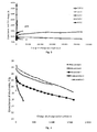
fig 3 is shown a cycle life of unconditioned superapcitors at different working voltages (Uw is noted in figure). Cycling was performed between working voltage Uw and Uw/2. - In the
fig 4 is shown cycle-life according to the capacitance of inventive and comparative supercapacitors, which were cycled between 4.0V and 2.0V. Commonly a lifetime of supercapacitor is counted to the capacitance value of 70% of the initial capacitance. - In the
fig 5 is shown cycle-life according to the resistance of inventive and comparative supercapacitors, which were cycled between 4.0V and 2.0V. Commonly a lifetime of supercapacitor is counted to the ESR value of 200% of the initial resistance. - Following examples specify the inventive matter and show the application limits.
- Polarisable carbon electrodes were prepared as follows.
- The mixture of 92% (wt.) carbon and 8% (wt.) polytetrafluoroethylene (PTFE, Aldrich, 60% suspension in water) was rolled stepwise into the carbon film with a final thickness of 80-100µm. After drying, the raw electrode sheets were coated from one side with a thin aluminium layer (2 ± 1 µm) using the physical vapour deposition method. The electrodes were attached to current collector: Aluminium (Al) foil, and interleaved with an ion-permeable separator paper from Nippon Kodoshi®. The electrode pairs from positively and negatively charged electrodes were connected in parallel. The electrode pack prepared was placed in a sealed aluminium container and stored under vacuum to degas the electrode stack and then impregnated with the electrolyte. In following examples, the electrolyte was 1.8M triethylmethylammonium tetrafluoroborate (TEMA) in anhydrous acetonitrile (AN, Riedel-de Haën, H2O <0.003%). [0001] However, it is well understood to the experts skilled in the field that the invention is not limited to this particular electrolyte and it can be whatever organic electrolyte including organic solvents: nitriles such as acetonitrile, acrylonitrile and propionitrile ; sulfoxides such as dimethyl, diethyl, ethyl methyl and benzylmethyl sulfoxide ; amides such as dimethyl formamide and pyrrolidones such as N-methylpyrrolidone, polar aprotic organic solvent such as a cyclic ester, chain carbonate, cyclic carbonate, chain ether and/or cyclic ether solvent or a mixture of such solvents and a salt. The electrolyte salt can be selected from the group of tetrafluorborates, or hexafluorophosphates or trifluoromethanesulfonate of tetraalkylammonium, tetrakis(dialkylamino) phosphonium, N,N-dialkyl-1,4-diazabicyclo[2.2.2]octanediium or their mixture. The electrolyte can be also at least one ionic liquids such selected from the group consisting of: butyltrimethylammonium bis(trifluoromethylsulfonyl)imide, 1-ethyl-3-methylimidazolium bis(trifluoromethylsulfonyl)imide, 1-methyl-3-propylimidazolium bis(trifluoromethylsulfonyl)imide, 1-hexyl-3-methylimidazolium bis(trifluoromethylsulfonyl)imide, 1-methyl-3-propylimidazolium iodide, 1-ethyl-3-methylimidazolium thiocyanate, 1-methyl-1-propylpiperidinium bis(trifluoromethylsulfonyl)imide, 1-butyl-2-methylpyridinium bis(trifluoromethylsulfonyl)imide, 1-butyl-4-methylpyridinium bis(trifluoromethylsulfonyl)imide, 1-butyl-1-methylpyrrolidinium bis(trifluoromethylsulfonyl)imide, diethylmethylsulfonium bis(trifluoromethylsulfonyl)imide, lithium bis(trifluoromethylsulfonyl)imide, and mixtures thereof.
- After filling with the electrolyte, the supercapacitor cell is stored for penetration of micropores by electrolyte. The storing time depends from the storing temperature, for example in the storing temperature 60° C the storing time is at least 48h which guarantees that the micropores are fully penetrated by the electrolyte. For the person skilled in the art is clear that storing supercapacitor in room temperature or in condition of the vacuum or high pressure the storing time of the supercapacitor can be increased or decreased to have the micropores fully penetrated by the electrolyte. In addition said storing time can depend on the type of the electrolyte used.
- The capacitance (C) and equivalent series resistance (ESR) values during the cycling were recorded by Impedance spectrometer at fixed voltage value using the frequency sweep within 100kHz to 10mHz.
- The capacitance was calculated at the frequency of 10mHz and the ESR at 100Hz. The cycling process between conditioning voltage Uc and Uc-ΔU was performed with potential sweep rate of 10mV/s, where Uc is a voltage in the conditioning step (for example Uc1 is a conditioning voltage in the
step 1 up to Ucn-1 which is a conditioning voltage of the last but one step and Ucn is a conditioning voltage of the last step where Ucn is equal to the working voltage Uw; ΔU is a difference between maximum and minimum voltage during cycling (i.e. ΔU is from 0 to Uc whereas ΔU=0 means that there is no cycling and the voltage of the conditioning step is hold and increased step-by-step to the working voltage Uw. If the 0 < ΔU ≤Uc in the conditioning step the cycling is performed where the supercondensator is charged to voltage Uc and thereafter discharged to the voltage Uc-ΔU). ΔUc is a voltage step in the conditioning process. The ESR values during step-by-step conditioning process for Uc, comprised of Uc1 ... Ucn-1 up to Ucn=Uw were recorded by Impedance Spectrometer (Solartron) by using the DC potential sweep rate of 10mV/s and AC signal of 10mV at 1 kHz. - Following inventive examples explain the method of step-by-step conditioning of supercapacitors for increased working voltage. Table 1. Carbon materials used for making the supercapacitors.
- Table 1
Table 1 Carbon Company BET surface area, m2/g Total pore volume, cm3/g Micropore volume, cm3/g Carbide-de rived TiC950/80 0 Skeleton Technologies 1400 0.70 0.57 Coconut-d erived YP-50F Kuraray Chemical Co 1430 0.71 0.58 Phenolic resin-deriv ed RP-20 Kuraray Chemical Co 1570 0.73 0.65 Carbide-de rived TiC950/80 0LPT Skeleton Technologies 1500 0.70 0.60 Carbide-de rived TiC1000PT Skeleton Technologies 2030 1.13 0.72 - Inventive example 1 describes a step-by-step conditioning of carbide-derived carbon electrodes for working voltage of 4.0V.
- A supercapacitor composed from the carbide-derived carbon TiC950/800 (see in Table 1) electrodes was electrochemically stabilised by cycling with constant current (50mA/F) between 2.85V and 1.425V. Galvanostatic cycling was continued until the capacitance (C), ESR (R) and the round trip efficiency (RTE) reached the stable values. (Usually it takes 50 to 100 cycles.). After that the supercapacitor was charged-discharged with constant potential sweep rate of 10mV/s by increasing the maximum voltage step-by-step to the value of 4.0V. The voltage step (ΔUc) was as maximum 0.2V as described in Table 2. The lower limit in voltage during cycling was fixed at 1.5V. Five cycles were done at each conditioning voltage step (Uc). The step-by-step conditioning for working voltage of 4.0V may also be done by using the constant DC current, constant power (CP), gradually increased constant voltage, pulse-current, pulse-power and pulse-voltage and other charge-discharge cycling methods of supercapacitor with or without AC signal. Inventive example 2 describes step-by-step conditioning as in Inventive example 1 with a difference that the coconut shell derived activated carbon (CSDAC) electrodes were used in supercapacitor. Table 2. Change of the ESR during conditioning process from 3V to 4V of CDC based supercapacitor. Charge-discharge cycling was done from Uc to 1.5V at each conditioning voltage (Uc1 ... Uc10).
-
Table 2 Voltage (Uc), V Relative ESR [%] at maximum voltage value 1st cycle 2nd cycle 3rd cycle 4th cycle 5th cycle 3.0 100% 100.9 101.0 101.9 102.0 3.2 100% 101.3 101.8 101.7 102.2 3.3 100% 101.0 101.7 102.5 103.1 3.4 100% 102.5 103.4 105.0 105.7 3.5 100% 102.5 104.6 106.2 106.9 3.6 100% 104.2 105.8 107.0 107.6 3.7 100% 103.3 104.2 105.5 105.8 3.8 100% 103.6 104.9 105.4 105.7 3.9 100% 103.9 104.0 104.7 105.1 4.0 100% 101.8 101.9 102.0 102.4 - Inventive example 3 describes step-by-step conditioning as in Inventive example 1 with a difference that the phenolic resin derived activated carbon (PRDAC) electrodes were used in supercapacitor.
- Table 3. Decay of supercapacitor performance during charge-discharge cycling between 4.0V to 1.5V in terms of the relative increase of ESR measured at 4.0V.
-
Table 3 Example # Electrode material 1st cycle 2nd cycle 3rd cycle 4th cycle 5th cycle Inventive example No. 1 CDC 0% 1.8% 1.9% 2.0% 2.4% Inventive example No. 2 CSDAC 0% 1.8% 3.3% 3.9% 5.1% Inventive example No. 3 PRDAC 0% 3.5% 4.5% 5.7% 7.4% - Different decays during first cycles at Uw=4.0V observed in Inventive examples 1-3 presented in Table 3, are explained by different chemical purity of carbon materials. CDC of Inventive example 1 represents the best performance mainly because it is produced from the precursor (TiC), which does not contain oxygen. Therefore, this carbon is free of oxygen containing functional groups, which otherwise would increase the decay of respective supercapacitor. Secondly, the CDC TiC950/800 is post-treated in hydrogen at high temperature that chemically purifies the surface of carbon.
- Inventive example 4 describes galvanostatic cycling of "1000F" CDC based prismatic supercapacitor stepwise conditioned to the working voltage of 4.0V.
- The results shown in
Figure 1 confirm the stable performance in terms of a temperature change, expansion/contraction and a linear voltage profile of the supercapacitor during cycling between 4.0V and 2.0V. - Comparative example 1, shown in
Figure 2 , represents the opposite case where a galvanostatic cycling of "1000F" CDC based prismatic supercapacitor not conditioned by the method of this invention, is unsuccessfully attempted according to the method of the present invention to charge to working voltage Uw 4.0V. This figure shows that working voltage Uw 4V was not possible to reach because of the temperature increase and expansion of the supercapacitor during first charge cycle went over the reasonable values. Further running of the experiment was not safe and was stopped at the ∼3.5V. - Next examples serve as comparative examples for demonstrating the state of the art supercapacitors and also for showing the purview of present invention.
Figure 3 describes the performance of supercapacitors, which were made of carbide-derived carbon TiC950/800LPT (see Table 1) according to the method of making supercapacitors, but were charged-discharged between Uw and Uw/2 without preliminary step-by-step conditioning up to working voltage Uw. Uw in these examples was varied from 2.85V to 4.0V. InFigure 3 , it is clearly seen that the decay of cycle life increases with increasing the Uw. It can also be seen that performance of supercapacitors regarding charge-discharge cycling drastically worsens when Uw is increased from 2.85V to 3V. Therefore, the step-by-step conditioning of supercapacitors by the method of this invention gives advantage for applying to the supercapacitor the working voltage of 3.0V and up. - An important role of step-by-step training is comparatively presented in
Figures 4 and5 , where a cycle life of step-by-step conditioned supercapacitors of Inventive Examples 5-7 is compared to unconditioned supercapacitors of Comparative Examples 2-3. Numerical characteristics of these supercapacitors are collected in Table 4, which clearly show the advantage of this invention over the state-of-the-art supercapacitors cycled between 4V and 2V. - Table 4. Rated capacitance (CR), life span at 70% of the initial and the rate of decay of supercapacitors during charge-discharge cycling between 4V to 2V.
-
Table 4 Example # Carbon CR, (F/g) @BOL* Capacitance decrease by 100 cycles No. of cycles @ EOL* (70% of C0) Inventive example No. 5 Carbide derived TiC1000PT 26.9 6% 1500 Inventive example No. 6 Carbide derived TiC950/800LPT 25.7 6% 1500 Inventive example No. 7 Coconut derived YP-50F 22.7 7% 1600 Comparative example No. 2 Carbide derived TiC950/800LPT 23.2 25% 165 Comparative example No. 3 Coconut derived YP-50F 20.9 29% 100 *BOL is beginning of the life; EOL is the end of the life - The present invention relates to the method of increasing the working voltage of electrical double layer capacitor with enhanced working voltage, which has electrodes fabricated from porous carbon powder in which the pore sizes and the specific surface are created by extracting the non-carbon atoms from the carbon-rich organic or mineral compounds. The method is performed by step-by-step treatment of supercapacitor with the conditioning voltage (Uc), which is increased gradually up to the working voltage (Uw) by the voltage step (DUc) which is less or equal to 0.2V.
Claims (10)
- A method of conditioning a supercapacitor to its working voltage, where the supercapacitor comprising at least one pair of the positively and negatively charged electrodes, including at least one polarisable micro/mesoporous carbon electrode, interleaved with porous ion-conductive separator and immersed in an electrolyte, where the destructive effect of the heat of adsorption is suppressed by a multistep conditioning process, where, before the conditioning of the supercapacitor, the supercapacitor cell is stored after filling with the electrolyte for penetration of micropores by electrolyte followed by step-by-step treatment of the supercapacitor with the conditioning voltage (Uc), which is increased gradually up to the working voltage (Uw) by the voltage step (ΔUc) which is less than 0.3V, wherein during the conditioning step is performed the voltage cycling where the supercapacitor is charged to the conditioning voltage (Uc) and thereafter discharged to the voltage Uc-ΔU where the ΔU is between 0 and Uc.
- The method according to the claim 1 wherein the number of the conditioning steps is predetermined by voltage step (ΔUc) so that the supercapacitor working voltage is reached.
- The method according to claim 1 wherein supercapacitor before treatment by conditioning voltage (Uc) is electrochemically stabilised by galvanostatic cycling at Uc of less than 3.0V until stable performance according to ESR and capacitance is obtained.
- The method according to claim 1 wherein micro/mesoporous carbon is carbide-derived carbon.
- The method according to claim 1 wherein micro/mesoporous carbon is coconut shell derived activated carbon.
- The method according to claim 1 wherein micro/mesoporous carbon is phenolic resin derived activated carbon.
- The method according to the claim 1 wherein the electrolyte used for immersion of the micro/mesoporous carbon electrode is selected from the organic electrolyte including organic solvents: nitriles such as acetonitrile, acrylonitrile and propionitrile; sulfoxides such as dimethyl, diethyl, ethyl methyl and benzylmethyl sulfoxide; amides such as dimethyl formamide and pyrrolidones such as N-methylpyrrolidone, polar aprotic organic solvent such as a cyclic ester, chain carbonate, cyclic carbonate, chain ether and/or cyclic ether solvent or a mixture of such solvents and a salt.
- The method according to the claim 7 wherein the electrolyte salt can be selected from the group of tetrafluorborates, or hexafluorophosphates or trifluoromethanesulfonate of tetraalkylammonium, tetrakis(dialkylamino) phosphonium, N,N-dialkyl-1,4-diazabicyclo[2.2.2]octanediium or their mixture.
- The method according to the claim 1 wherein the electrolyte used for immersion of the micro/mesoporous carbon electrode can be also at least one ionic liquids such selected from the group consisting of:butyltrimethylammonium bis(trifluoromethylsulfonyl)imide, 1-ethyl-3-methylimidazolium bis(trifluoromethylsulfonyl)imide, 1-methyl-3-propylimidazolium bis(trifluoromethylsulfonyl)imide, 1-hexyl-3-methylimidazolium bis(trifluoromethylsulfonyl)imide, 1-methyl-3-propylimidazolium iodide, 1-ethyl-3-methylimidazolium thiocyanate, 1-methyl-1-propylpiperidinium bis(trifluoromethylsulfonyl)imide, 1-butyl-2-methylpyridinium bis(trifluoromethylsulfonyl)imide, 1-butyl-4-methylpyridinium bis(trifluoromethylsulfonyl)imide, 1-butyl-1-methylpyrrolidinium bis(trifluoromethylsulfonyl)imide, diethylmethylsulfonium bis(trifluoromethylsulfonyl)imide, lithium bis(trifluoromethylsulfonyl)imide, and mixtures thereof.
- The method according to the claim 1 wherein before conditioning the supercapacitor the supecapacitor cell is stored after filling with the electrolyte at the temperature which is higher than a room temperature for penetration of micropores by electrolyte.
Priority Applications (4)
| Application Number | Priority Date | Filing Date | Title |
|---|---|---|---|
| PL11787805T PL2633532T3 (en) | 2010-10-31 | 2011-10-31 | A method of conditioning a supercapacitor to its working voltage |
| PL15001742T PL2978003T3 (en) | 2010-10-31 | 2011-10-31 | Method of conditioning a supercapacitor to its working voltage and supercapacitor |
| EP15001742.4A EP2978003B1 (en) | 2010-10-31 | 2011-10-31 | Method of conditioning a supercapacitor to its working voltage and supercapacitor |
| NO15001742A NO2978003T3 (en) | 2010-10-31 | 2011-10-31 |
Applications Claiming Priority (2)
| Application Number | Priority Date | Filing Date | Title |
|---|---|---|---|
| US40863510P | 2010-10-31 | 2010-10-31 | |
| PCT/EP2011/069176 WO2012056050A2 (en) | 2010-10-31 | 2011-10-31 | An electrical double layer capacitor with enhanced working voltage |
Related Child Applications (2)
| Application Number | Title | Priority Date | Filing Date |
|---|---|---|---|
| EP15001742.4A Division EP2978003B1 (en) | 2010-10-31 | 2011-10-31 | Method of conditioning a supercapacitor to its working voltage and supercapacitor |
| EP15001742.4A Division-Into EP2978003B1 (en) | 2010-10-31 | 2011-10-31 | Method of conditioning a supercapacitor to its working voltage and supercapacitor |
Publications (2)
| Publication Number | Publication Date |
|---|---|
| EP2633532A2 EP2633532A2 (en) | 2013-09-04 |
| EP2633532B1 true EP2633532B1 (en) | 2015-07-29 |
Family
ID=45033936
Family Applications (2)
| Application Number | Title | Priority Date | Filing Date |
|---|---|---|---|
| EP11787805.8A Active EP2633532B1 (en) | 2010-10-31 | 2011-10-31 | A method of conditioning a supercapacitor to its working voltage |
| EP15001742.4A Active EP2978003B1 (en) | 2010-10-31 | 2011-10-31 | Method of conditioning a supercapacitor to its working voltage and supercapacitor |
Family Applications After (1)
| Application Number | Title | Priority Date | Filing Date |
|---|---|---|---|
| EP15001742.4A Active EP2978003B1 (en) | 2010-10-31 | 2011-10-31 | Method of conditioning a supercapacitor to its working voltage and supercapacitor |
Country Status (9)
| Country | Link |
|---|---|
| US (1) | US8911510B2 (en) |
| EP (2) | EP2633532B1 (en) |
| KR (1) | KR101933633B1 (en) |
| EA (1) | EA025540B1 (en) |
| ES (2) | ES2551176T3 (en) |
| HU (2) | HUE036568T2 (en) |
| NO (1) | NO2978003T3 (en) |
| PL (2) | PL2978003T3 (en) |
| WO (1) | WO2012056050A2 (en) |
Families Citing this family (11)
| Publication number | Priority date | Publication date | Assignee | Title |
|---|---|---|---|---|
| WO2013090927A1 (en) | 2011-12-16 | 2013-06-20 | Calgon Carbon Corporation | Double layer capacitors |
| WO2013192162A1 (en) * | 2012-06-20 | 2013-12-27 | E. I. Du Pont De Nemours And Company | Low temperature heat transfer fluid and system |
| US9318271B2 (en) * | 2012-06-21 | 2016-04-19 | Schlumberger Technology Corporation | High temperature supercapacitor |
| DE102013112415A1 (en) * | 2013-11-12 | 2015-05-13 | Ludwig-Maximilians-Universität München | Device and method for examining one or more phase objects |
| KR20170081199A (en) * | 2014-11-03 | 2017-07-11 | 사켐,인코포레이티드 | Electrolytic compositions base on mixed alkyl quaternary ammonium or phosphonium salts for electric energy storage and generation devices |
| GB2548128B (en) * | 2016-03-09 | 2021-12-15 | Zapgo Ltd | Method of reducing outgassing |
| EP3459097A4 (en) | 2016-05-20 | 2020-05-06 | AVX Corporation | WATER-FREE ELECTROLYT FOR AN ULTRA-CAPACITOR |
| CN109155204B (en) | 2016-05-20 | 2020-12-22 | 阿维科斯公司 | Electrode structure for supercapacitor |
| MY194849A (en) | 2016-05-20 | 2022-12-19 | Kyocera Avx Components Corp | Ultracapacitor for use at high temperatures |
| CN108766775B (en) * | 2018-05-25 | 2019-05-28 | 常州大学 | A kind of preparation method and applications of ultralow temperature high capacity supercapacitor |
| RU190386U1 (en) * | 2019-02-21 | 2019-07-01 | Общество с ограниченной ответственностью «Углерод ЧГ» | ACTIVE ELECTRODE FOR SUPERCONDENSATOR |
Family Cites Families (11)
| Publication number | Priority date | Publication date | Assignee | Title |
|---|---|---|---|---|
| AT345402B (en) | 1973-12-05 | 1978-09-11 | Siemens Ag | METHOD OF REFORMING ELECTROLYTE CAPACITORS |
| GB2179793B (en) | 1985-08-28 | 1988-09-21 | Stc Plc | Pulsing capacitors in manufacture |
| UA30509A (en) * | 1998-05-18 | 2000-11-15 | Товариство З Обмеженою Відповідальністю "Юнк-Бюро" | Electrolyte for electrochemical double-layer condenser |
| JP3973183B2 (en) * | 1998-09-22 | 2007-09-12 | 株式会社パワーシステム | Manufacturing method of electric double layer capacitor |
| TW505934B (en) * | 2001-02-01 | 2002-10-11 | Luxon Energy Devices Corp | Manufacture method of electrochemical capacitor |
| JP2004128035A (en) | 2002-09-30 | 2004-04-22 | Nippon Chemicon Corp | Method of manufacturing solid-state electrolytic capacitor |
| JP2006261599A (en) | 2005-03-18 | 2006-09-28 | Japan Gore Tex Inc | Manufacturing method of electric double layer capacitor |
| JP4706066B2 (en) | 2005-08-19 | 2011-06-22 | 独立行政法人産業技術総合研究所 | Electrochemical capacitor and electrode material used therefor |
| DE102008060546B3 (en) | 2008-12-04 | 2010-04-01 | Imp Gmbh | Process for reforming electrolytic capacitors |
| US9640334B2 (en) * | 2010-01-25 | 2017-05-02 | Nanotek Instruments, Inc. | Flexible asymmetric electrochemical cells using nano graphene platelet as an electrode material |
| US9053870B2 (en) * | 2010-08-02 | 2015-06-09 | Nanotek Instruments, Inc. | Supercapacitor with a meso-porous nano graphene electrode |
-
2011
- 2011-10-31 EA EA201300517A patent/EA025540B1/en not_active IP Right Cessation
- 2011-10-31 PL PL15001742T patent/PL2978003T3/en unknown
- 2011-10-31 PL PL11787805T patent/PL2633532T3/en unknown
- 2011-10-31 US US13/882,664 patent/US8911510B2/en not_active Expired - Fee Related
- 2011-10-31 KR KR1020137014180A patent/KR101933633B1/en not_active Expired - Fee Related
- 2011-10-31 WO PCT/EP2011/069176 patent/WO2012056050A2/en not_active Ceased
- 2011-10-31 EP EP11787805.8A patent/EP2633532B1/en active Active
- 2011-10-31 HU HUE15001742A patent/HUE036568T2/en unknown
- 2011-10-31 ES ES11787805.8T patent/ES2551176T3/en active Active
- 2011-10-31 ES ES15001742.4T patent/ES2657342T3/en active Active
- 2011-10-31 EP EP15001742.4A patent/EP2978003B1/en active Active
- 2011-10-31 NO NO15001742A patent/NO2978003T3/no unknown
- 2011-10-31 HU HUE11787805A patent/HUE025995T2/en unknown
Also Published As
| Publication number | Publication date |
|---|---|
| WO2012056050A3 (en) | 2012-07-26 |
| HUE025995T2 (en) | 2016-05-30 |
| ES2657342T3 (en) | 2018-03-02 |
| EA025540B1 (en) | 2017-01-30 |
| EP2633532A2 (en) | 2013-09-04 |
| US20130283580A1 (en) | 2013-10-31 |
| PL2978003T3 (en) | 2018-04-30 |
| WO2012056050A2 (en) | 2012-05-03 |
| KR101933633B1 (en) | 2018-12-28 |
| KR20140007803A (en) | 2014-01-20 |
| PL2633532T3 (en) | 2015-12-31 |
| HUE036568T2 (en) | 2018-07-30 |
| EP2978003A2 (en) | 2016-01-27 |
| EP2978003A3 (en) | 2016-05-25 |
| US8911510B2 (en) | 2014-12-16 |
| EA201300517A1 (en) | 2013-11-29 |
| NO2978003T3 (en) | 2018-01-27 |
| ES2551176T3 (en) | 2015-11-16 |
| EP2978003B1 (en) | 2017-08-30 |
Similar Documents
| Publication | Publication Date | Title |
|---|---|---|
| EP2978003B1 (en) | Method of conditioning a supercapacitor to its working voltage and supercapacitor | |
| JP2014530502A (en) | High voltage electrochemical double layer capacitor | |
| US20170084402A1 (en) | Low resistance ultracapacitor electrode and manufacturing method thereof | |
| US10211001B2 (en) | Ultracapacitor with improved aging performance | |
| JP2016535456A (en) | High capacitance activated carbon and carbon-based electrode | |
| KR20160083855A (en) | Alkali metal ion capacitor, method for producing the same and method for charging and discharging the same | |
| EP3109877A1 (en) | Capacitor and method for charging and discharging same | |
| JP4370019B2 (en) | Electric field activation method for electric double layer capacitor | |
| KR102801846B1 (en) | Method for manufacturing Electric Double Layer Capacitor with high voltage | |
| Arbizzani et al. | Ilhypos ionic liquid-based supercapacitors | |
| KR100706715B1 (en) | Hybrid battery | |
| KR100663832B1 (en) | Hybrid battery | |
| KR20140037074A (en) | Carbon electrodes and electrochemical capacitors | |
| HK1254992A1 (en) | Electrolyte for three-volt ultracapacitor | |
| Béguin et al. | Guidelines for the optimization of EDLC carbon electrodes | |
| HK1212504A1 (en) | Electrolyte for three-volt ultracapacitor | |
| HK1212504B (en) | Electrolyte for three-volt ultracapacitor |
Legal Events
| Date | Code | Title | Description |
|---|---|---|---|
| PUAI | Public reference made under article 153(3) epc to a published international application that has entered the european phase |
Free format text: ORIGINAL CODE: 0009012 |
|
| 17P | Request for examination filed |
Effective date: 20130530 |
|
| AK | Designated contracting states |
Kind code of ref document: A2 Designated state(s): AL AT BE BG CH CY CZ DE DK EE ES FI FR GB GR HR HU IE IS IT LI LT LU LV MC MK MT NL NO PL PT RO RS SE SI SK SM TR |
|
| DAX | Request for extension of the european patent (deleted) | ||
| RAP1 | Party data changed (applicant data changed or rights of an application transferred) |
Owner name: OUE SKELETON TECHNOLOGIES GROUP |
|
| REG | Reference to a national code |
Ref country code: DE Ref legal event code: R079 Ref document number: 602011018314 Country of ref document: DE Free format text: PREVIOUS MAIN CLASS: H01G0009155000 Ipc: H01G0011140000 |
|
| GRAP | Despatch of communication of intention to grant a patent |
Free format text: ORIGINAL CODE: EPIDOSNIGR1 |
|
| RIC1 | Information provided on ipc code assigned before grant |
Ipc: H01G 11/14 20130101AFI20150115BHEP Ipc: H01G 11/84 20130101ALI20150115BHEP Ipc: H01G 11/58 20130101ALI20150115BHEP Ipc: H01G 11/52 20130101ALI20150115BHEP |
|
| INTG | Intention to grant announced |
Effective date: 20150204 |
|
| GRAS | Grant fee paid |
Free format text: ORIGINAL CODE: EPIDOSNIGR3 |
|
| GRAA | (expected) grant |
Free format text: ORIGINAL CODE: 0009210 |
|
| AK | Designated contracting states |
Kind code of ref document: B1 Designated state(s): AL AT BE BG CH CY CZ DE DK EE ES FI FR GB GR HR HU IE IS IT LI LT LU LV MC MK MT NL NO PL PT RO RS SE SI SK SM TR |
|
| REG | Reference to a national code |
Ref country code: GB Ref legal event code: FG4D |
|
| REG | Reference to a national code |
Ref country code: CH Ref legal event code: EP |
|
| REG | Reference to a national code |
Ref country code: AT Ref legal event code: REF Ref document number: 739861 Country of ref document: AT Kind code of ref document: T Effective date: 20150815 |
|
| REG | Reference to a national code |
Ref country code: IE Ref legal event code: FG4D |
|
| REG | Reference to a national code |
Ref country code: DE Ref legal event code: R096 Ref document number: 602011018314 Country of ref document: DE |
|
| REG | Reference to a national code |
Ref country code: CH Ref legal event code: NV Representative=s name: KIRKER AND CIE S.A., CH |
|
| REG | Reference to a national code |
Ref country code: SE Ref legal event code: TRGR |
|
| REG | Reference to a national code |
Ref country code: FR Ref legal event code: PLFP Year of fee payment: 5 |
|
| REG | Reference to a national code |
Ref country code: ES Ref legal event code: FG2A Ref document number: 2551176 Country of ref document: ES Kind code of ref document: T3 Effective date: 20151116 |
|
| REG | Reference to a national code |
Ref country code: NO Ref legal event code: T2 Effective date: 20150729 |
|
| REG | Reference to a national code |
Ref country code: AT Ref legal event code: MK05 Ref document number: 739861 Country of ref document: AT Kind code of ref document: T Effective date: 20150729 |
|
| REG | Reference to a national code |
Ref country code: LT Ref legal event code: MG4D |
|
| REG | Reference to a national code |
Ref country code: PL Ref legal event code: T3 |
|
| REG | Reference to a national code |
Ref country code: NL Ref legal event code: FP |
|
| PG25 | Lapsed in a contracting state [announced via postgrant information from national office to epo] |
Ref country code: LV Free format text: LAPSE BECAUSE OF FAILURE TO SUBMIT A TRANSLATION OF THE DESCRIPTION OR TO PAY THE FEE WITHIN THE PRESCRIBED TIME-LIMIT Effective date: 20150729 Ref country code: GR Free format text: LAPSE BECAUSE OF FAILURE TO SUBMIT A TRANSLATION OF THE DESCRIPTION OR TO PAY THE FEE WITHIN THE PRESCRIBED TIME-LIMIT Effective date: 20151030 Ref country code: LT Free format text: LAPSE BECAUSE OF FAILURE TO SUBMIT A TRANSLATION OF THE DESCRIPTION OR TO PAY THE FEE WITHIN THE PRESCRIBED TIME-LIMIT Effective date: 20150729 |
|
| PG25 | Lapsed in a contracting state [announced via postgrant information from national office to epo] |
Ref country code: RS Free format text: LAPSE BECAUSE OF FAILURE TO SUBMIT A TRANSLATION OF THE DESCRIPTION OR TO PAY THE FEE WITHIN THE PRESCRIBED TIME-LIMIT Effective date: 20150729 Ref country code: AT Free format text: LAPSE BECAUSE OF FAILURE TO SUBMIT A TRANSLATION OF THE DESCRIPTION OR TO PAY THE FEE WITHIN THE PRESCRIBED TIME-LIMIT Effective date: 20150729 Ref country code: PT Free format text: LAPSE BECAUSE OF FAILURE TO SUBMIT A TRANSLATION OF THE DESCRIPTION OR TO PAY THE FEE WITHIN THE PRESCRIBED TIME-LIMIT Effective date: 20151130 Ref country code: IS Free format text: LAPSE BECAUSE OF FAILURE TO SUBMIT A TRANSLATION OF THE DESCRIPTION OR TO PAY THE FEE WITHIN THE PRESCRIBED TIME-LIMIT Effective date: 20151129 Ref country code: HR Free format text: LAPSE BECAUSE OF FAILURE TO SUBMIT A TRANSLATION OF THE DESCRIPTION OR TO PAY THE FEE WITHIN THE PRESCRIBED TIME-LIMIT Effective date: 20150729 |
|
| REG | Reference to a national code |
Ref country code: EE Ref legal event code: FG4A Ref document number: E011553 Country of ref document: EE Effective date: 20151209 Ref country code: DE Ref legal event code: R082 Ref document number: 602011018314 Country of ref document: DE |
|
| PG25 | Lapsed in a contracting state [announced via postgrant information from national office to epo] |
Ref country code: DK Free format text: LAPSE BECAUSE OF FAILURE TO SUBMIT A TRANSLATION OF THE DESCRIPTION OR TO PAY THE FEE WITHIN THE PRESCRIBED TIME-LIMIT Effective date: 20150729 Ref country code: SK Free format text: LAPSE BECAUSE OF FAILURE TO SUBMIT A TRANSLATION OF THE DESCRIPTION OR TO PAY THE FEE WITHIN THE PRESCRIBED TIME-LIMIT Effective date: 20150729 |
|
| PGFP | Annual fee paid to national office [announced via postgrant information from national office to epo] |
Ref country code: EE Payment date: 20151130 Year of fee payment: 5 |
|
| REG | Reference to a national code |
Ref country code: DE Ref legal event code: R097 Ref document number: 602011018314 Country of ref document: DE |
|
| REG | Reference to a national code |
Ref country code: HU Ref legal event code: AG4A Ref document number: E025995 Country of ref document: HU |
|
| PG25 | Lapsed in a contracting state [announced via postgrant information from national office to epo] |
Ref country code: RO Free format text: LAPSE BECAUSE OF FAILURE TO SUBMIT A TRANSLATION OF THE DESCRIPTION OR TO PAY THE FEE WITHIN THE PRESCRIBED TIME-LIMIT Effective date: 20150729 Ref country code: LU Free format text: LAPSE BECAUSE OF FAILURE TO SUBMIT A TRANSLATION OF THE DESCRIPTION OR TO PAY THE FEE WITHIN THE PRESCRIBED TIME-LIMIT Effective date: 20151031 |
|
| PLBE | No opposition filed within time limit |
Free format text: ORIGINAL CODE: 0009261 |
|
| STAA | Information on the status of an ep patent application or granted ep patent |
Free format text: STATUS: NO OPPOSITION FILED WITHIN TIME LIMIT |
|
| PG25 | Lapsed in a contracting state [announced via postgrant information from national office to epo] |
Ref country code: MC Free format text: LAPSE BECAUSE OF FAILURE TO SUBMIT A TRANSLATION OF THE DESCRIPTION OR TO PAY THE FEE WITHIN THE PRESCRIBED TIME-LIMIT Effective date: 20150729 |
|
| 26N | No opposition filed |
Effective date: 20160502 |
|
| REG | Reference to a national code |
Ref country code: IE Ref legal event code: MM4A |
|
| PG25 | Lapsed in a contracting state [announced via postgrant information from national office to epo] |
Ref country code: SI Free format text: LAPSE BECAUSE OF FAILURE TO SUBMIT A TRANSLATION OF THE DESCRIPTION OR TO PAY THE FEE WITHIN THE PRESCRIBED TIME-LIMIT Effective date: 20150729 |
|
| REG | Reference to a national code |
Ref country code: FR Ref legal event code: PLFP Year of fee payment: 6 |
|
| PG25 | Lapsed in a contracting state [announced via postgrant information from national office to epo] |
Ref country code: IE Free format text: LAPSE BECAUSE OF NON-PAYMENT OF DUE FEES Effective date: 20151031 |
|
| PG25 | Lapsed in a contracting state [announced via postgrant information from national office to epo] |
Ref country code: BE Free format text: LAPSE BECAUSE OF FAILURE TO SUBMIT A TRANSLATION OF THE DESCRIPTION OR TO PAY THE FEE WITHIN THE PRESCRIBED TIME-LIMIT Effective date: 20150729 |
|
| REG | Reference to a national code |
Ref country code: EE Ref legal event code: MM4A Ref document number: E011553 Country of ref document: EE Effective date: 20161031 |
|
| PG25 | Lapsed in a contracting state [announced via postgrant information from national office to epo] |
Ref country code: BG Free format text: LAPSE BECAUSE OF FAILURE TO SUBMIT A TRANSLATION OF THE DESCRIPTION OR TO PAY THE FEE WITHIN THE PRESCRIBED TIME-LIMIT Effective date: 20150729 Ref country code: SM Free format text: LAPSE BECAUSE OF FAILURE TO SUBMIT A TRANSLATION OF THE DESCRIPTION OR TO PAY THE FEE WITHIN THE PRESCRIBED TIME-LIMIT Effective date: 20150729 |
|
| PG25 | Lapsed in a contracting state [announced via postgrant information from national office to epo] |
Ref country code: CY Free format text: LAPSE BECAUSE OF FAILURE TO SUBMIT A TRANSLATION OF THE DESCRIPTION OR TO PAY THE FEE WITHIN THE PRESCRIBED TIME-LIMIT Effective date: 20150729 |
|
| PG25 | Lapsed in a contracting state [announced via postgrant information from national office to epo] |
Ref country code: EE Free format text: LAPSE BECAUSE OF NON-PAYMENT OF DUE FEES Effective date: 20161031 |
|
| PG25 | Lapsed in a contracting state [announced via postgrant information from national office to epo] |
Ref country code: MT Free format text: LAPSE BECAUSE OF FAILURE TO SUBMIT A TRANSLATION OF THE DESCRIPTION OR TO PAY THE FEE WITHIN THE PRESCRIBED TIME-LIMIT Effective date: 20150729 |
|
| REG | Reference to a national code |
Ref country code: FR Ref legal event code: PLFP Year of fee payment: 7 |
|
| PG25 | Lapsed in a contracting state [announced via postgrant information from national office to epo] |
Ref country code: MK Free format text: LAPSE BECAUSE OF FAILURE TO SUBMIT A TRANSLATION OF THE DESCRIPTION OR TO PAY THE FEE WITHIN THE PRESCRIBED TIME-LIMIT Effective date: 20150729 |
|
| PG25 | Lapsed in a contracting state [announced via postgrant information from national office to epo] |
Ref country code: AL Free format text: LAPSE BECAUSE OF FAILURE TO SUBMIT A TRANSLATION OF THE DESCRIPTION OR TO PAY THE FEE WITHIN THE PRESCRIBED TIME-LIMIT Effective date: 20150729 |
|
| PGFP | Annual fee paid to national office [announced via postgrant information from national office to epo] |
Ref country code: TR Payment date: 20201027 Year of fee payment: 10 |
|
| PGFP | Annual fee paid to national office [announced via postgrant information from national office to epo] |
Ref country code: NO Payment date: 20201028 Year of fee payment: 10 Ref country code: CH Payment date: 20201030 Year of fee payment: 10 Ref country code: FI Payment date: 20201029 Year of fee payment: 10 Ref country code: CZ Payment date: 20201015 Year of fee payment: 10 Ref country code: HU Payment date: 20201031 Year of fee payment: 10 |
|
| PGFP | Annual fee paid to national office [announced via postgrant information from national office to epo] |
Ref country code: PL Payment date: 20201028 Year of fee payment: 10 |
|
| REG | Reference to a national code |
Ref country code: NO Ref legal event code: MMEP |
|
| REG | Reference to a national code |
Ref country code: FI Ref legal event code: MAE |
|
| REG | Reference to a national code |
Ref country code: CH Ref legal event code: PL |
|
| PG25 | Lapsed in a contracting state [announced via postgrant information from national office to epo] |
Ref country code: NO Free format text: LAPSE BECAUSE OF NON-PAYMENT OF DUE FEES Effective date: 20211031 Ref country code: HU Free format text: LAPSE BECAUSE OF NON-PAYMENT OF DUE FEES Effective date: 20211101 Ref country code: CZ Free format text: LAPSE BECAUSE OF NON-PAYMENT OF DUE FEES Effective date: 20211031 |
|
| PG25 | Lapsed in a contracting state [announced via postgrant information from national office to epo] |
Ref country code: LI Free format text: LAPSE BECAUSE OF NON-PAYMENT OF DUE FEES Effective date: 20211031 Ref country code: FI Free format text: LAPSE BECAUSE OF NON-PAYMENT OF DUE FEES Effective date: 20211031 Ref country code: CH Free format text: LAPSE BECAUSE OF NON-PAYMENT OF DUE FEES Effective date: 20211031 |
|
| PG25 | Lapsed in a contracting state [announced via postgrant information from national office to epo] |
Ref country code: PL Free format text: LAPSE BECAUSE OF NON-PAYMENT OF DUE FEES Effective date: 20211031 |
|
| PGFP | Annual fee paid to national office [announced via postgrant information from national office to epo] |
Ref country code: NL Payment date: 20231023 Year of fee payment: 13 |
|
| PGFP | Annual fee paid to national office [announced via postgrant information from national office to epo] |
Ref country code: GB Payment date: 20231025 Year of fee payment: 13 |
|
| PGFP | Annual fee paid to national office [announced via postgrant information from national office to epo] |
Ref country code: ES Payment date: 20231117 Year of fee payment: 13 |
|
| PGFP | Annual fee paid to national office [announced via postgrant information from national office to epo] |
Ref country code: SE Payment date: 20231025 Year of fee payment: 13 Ref country code: IT Payment date: 20231025 Year of fee payment: 13 Ref country code: FR Payment date: 20231023 Year of fee payment: 13 |
|
| PG25 | Lapsed in a contracting state [announced via postgrant information from national office to epo] |
Ref country code: TR Free format text: LAPSE BECAUSE OF NON-PAYMENT OF DUE FEES Effective date: 20211031 |
|
| REG | Reference to a national code |
Ref country code: NL Ref legal event code: MM Effective date: 20241101 |
|
| GBPC | Gb: european patent ceased through non-payment of renewal fee |
Effective date: 20241031 |
|
| REG | Reference to a national code |
Ref country code: SE Ref legal event code: EUG |
|
| PG25 | Lapsed in a contracting state [announced via postgrant information from national office to epo] |
Ref country code: GB Free format text: LAPSE BECAUSE OF NON-PAYMENT OF DUE FEES Effective date: 20241031 |
|
| PG25 | Lapsed in a contracting state [announced via postgrant information from national office to epo] |
Ref country code: NL Free format text: LAPSE BECAUSE OF NON-PAYMENT OF DUE FEES Effective date: 20241101 |
|
| PG25 | Lapsed in a contracting state [announced via postgrant information from national office to epo] |
Ref country code: FR Free format text: LAPSE BECAUSE OF NON-PAYMENT OF DUE FEES Effective date: 20241031 |
|
| PG25 | Lapsed in a contracting state [announced via postgrant information from national office to epo] |
Ref country code: IT Free format text: LAPSE BECAUSE OF NON-PAYMENT OF DUE FEES Effective date: 20241031 Ref country code: SE Free format text: LAPSE BECAUSE OF NON-PAYMENT OF DUE FEES Effective date: 20241101 |
|
| REG | Reference to a national code |
Ref country code: ES Ref legal event code: FD2A Effective date: 20251205 |
|
| PG25 | Lapsed in a contracting state [announced via postgrant information from national office to epo] |
Ref country code: ES Free format text: LAPSE BECAUSE OF NON-PAYMENT OF DUE FEES Effective date: 20241101 |
|
| PGFP | Annual fee paid to national office [announced via postgrant information from national office to epo] |
Ref country code: DE Payment date: 20251222 Year of fee payment: 15 |