EP2632802B1 - Bladder clamp and related methods and apparatus for wrapping loads - Google Patents
Bladder clamp and related methods and apparatus for wrapping loads Download PDFInfo
- Publication number
- EP2632802B1 EP2632802B1 EP11779537.7A EP11779537A EP2632802B1 EP 2632802 B1 EP2632802 B1 EP 2632802B1 EP 11779537 A EP11779537 A EP 11779537A EP 2632802 B1 EP2632802 B1 EP 2632802B1
- Authority
- EP
- European Patent Office
- Prior art keywords
- packaging material
- jaw member
- load
- belt
- assembly
- Prior art date
- Legal status (The legal status is an assumption and is not a legal conclusion. Google has not performed a legal analysis and makes no representation as to the accuracy of the status listed.)
- Active
Links
Images


Classifications
-
- B—PERFORMING OPERATIONS; TRANSPORTING
- B65—CONVEYING; PACKING; STORING; HANDLING THIN OR FILAMENTARY MATERIAL
- B65B—MACHINES, APPARATUS OR DEVICES FOR, OR METHODS OF, PACKAGING ARTICLES OR MATERIALS; UNPACKING
- B65B11/00—Wrapping, e.g. partially or wholly enclosing, articles or quantities of material, in strips, sheets or blanks, of flexible material
- B65B11/008—Wrapping, e.g. partially or wholly enclosing, articles or quantities of material, in strips, sheets or blanks, of flexible material by webs revolving around articles moved along the axis of revolution
-
- B—PERFORMING OPERATIONS; TRANSPORTING
- B65—CONVEYING; PACKING; STORING; HANDLING THIN OR FILAMENTARY MATERIAL
- B65B—MACHINES, APPARATUS OR DEVICES FOR, OR METHODS OF, PACKAGING ARTICLES OR MATERIALS; UNPACKING
- B65B11/00—Wrapping, e.g. partially or wholly enclosing, articles or quantities of material, in strips, sheets or blanks, of flexible material
- B65B11/02—Wrapping articles or quantities of material, without changing their position during the wrapping operation, e.g. in moulds with hinged folders
- B65B11/025—Wrapping articles or quantities of material, without changing their position during the wrapping operation, e.g. in moulds with hinged folders by webs revolving around stationary articles
-
- B—PERFORMING OPERATIONS; TRANSPORTING
- B65—CONVEYING; PACKING; STORING; HANDLING THIN OR FILAMENTARY MATERIAL
- B65B—MACHINES, APPARATUS OR DEVICES FOR, OR METHODS OF, PACKAGING ARTICLES OR MATERIALS; UNPACKING
- B65B11/00—Wrapping, e.g. partially or wholly enclosing, articles or quantities of material, in strips, sheets or blanks, of flexible material
- B65B11/04—Wrapping, e.g. partially or wholly enclosing, articles or quantities of material, in strips, sheets or blanks, of flexible material the articles being rotated
- B65B11/045—Wrapping, e.g. partially or wholly enclosing, articles or quantities of material, in strips, sheets or blanks, of flexible material the articles being rotated by rotating platforms supporting the articles
Definitions
- This disclosure relates generally to methods and apparatus for wrapping a load with packaging material, and more particularly, to methods and apparatus for clamping packaging material.
- Loads have been wrapped with packaging material by dispensing the packaging material with a packaging material dispenser, and providing relative rotation between the load and the packaging material dispenser to cover the load with the packaging material.
- Semi-automatic wrapping machines exist that require attachment of a leading end portion of the packaging material to the load by an operator prior to wrapping of the load. This is typically accomplished by collapsing the leading end portion into a rope, and then inserting the rope between layers of the load or tying the rope to an edge of a pallet or any suitable outcropping on the load. This attachment must be strong enough to resist a pulling force exerted by the packaging material dispenser on the packaging material during initiation of the relative rotation between the load and the packaging material dispenser.
- This type of attachment makes removing the packaging material difficult after the load has been shipped to its destination and is being unwrapped. Further, throughput is decreased due to the operator having to attach the leading end portion of the packaging material to each load before wrapping the load. Additionally, collapsing the leading end portion of the packaging material reduces its effective height, thus requiring the use of more packaging material to adequately cover the load.
- Automatic wrapping machines typically use packaging material clamps that grip the packaging material between two opposed surfaces and use electrical or pneumatic actuators to open and close the clamps.
- packaging material clamps may be overwrapped by the packaging material during wrapping, and may create a "tenting" effect due to their distance from the load, resulting in wasted packaging material and loosely wrapped loads. Additionally, such clamps are expensive and may require costly maintenance for the electrical and mechanical actuators. Furthermore, such clamps tend to collapse the packaging material or require collapsing of the packaging material prior to clamping, thus reducing the effective height of the packaging material.
- US 4,761,934 B discloses a clamp for clamping a web during stretch wrapping which includes a first longitudinally extending clamp element for engaging the web, a second longitudinally extending clamp element extendable in a direction generally parallel to the longitudinal direction of the first clamp element for clamping the web between the second clamp element and the first clamp element as the second clamp element is longitudinally extending in a direction parallel to the longitudinal direction of the first clamp element.
- the present disclosure is directed to overcoming one or more of the above-noted problems.
- a clamp assembly may include a first jaw member which may have a selectively inflatable bladder.
- the clamp assembly may further include a second jaw member which may have a belt. The first jaw member and the second jaw member may be configured to clamp material between the selectively inflatable bladder and the belt.
- the method may further include inflating the inflatable bladder against a first surface of the packaging material and moving the second jaw member relative to the first jaw member while engaging a second surface of the packaging material opposite the first surface with the belt.
- the method may include moving the belt relative to the second jaw member such that after a portion of the belt contacts a portion of the packaging material, the portion of the belt may remain fixed relative to the portion of the packaging material as the second jaw member moves relative to the first jaw member.
- the method may further include clamping the packaging material between the inflatable bladder and the belt without reducing a height of the packaging material.
- a packaging material clamp assembly may include a first longitudinally extending jaw member which may have a selectively expandable bladder, and a second longitudinally extending jaw member which may have a belt opposed to the selectively expandable bladder.
- first and second longitudinally extending jaw members may be configured to clamp packaging material between the selectively expandable bladder and the belt.
- an apparatus for wrapping a load with packaging material may include a packaging material dispenser which may be configured to dispense packaging material to the load.
- the apparatus may include a relative rotation assembly which may be configured to provide relative rotation between the packaging material dispenser and the load.
- the apparatus may include a clamp assembly which may have a first longitudinally extending jaw member including a selectively expandable bladder and a second longitudinally extending jaw member including a belt opposed to the selectively expandable bladder. The first and second longitudinally extending jaw members may be configured to clamp the packaging material between the selectively expandable bladder and the belt.
- a method for wrapping a load with packaging material may include positioning the load in a position to be wrapped, providing relative rotation between a packaging material dispenser and the load while the packaging material dispenser dispenses the packaging material, and extending a first longitudinally extending jaw member into a path of the dispensed packaging material, wherein the first longitudinally extending jaw member may include a selectively expandable bladder thereon.
- the method may include overwrapping the first longitudinally extending jaw member with packaging material such that the packaging material is adjacent the selectively expandable bladder, and extending a second longitudinally extending jaw member alongside the first longitudinally extending jaw member, wherein the second longitudinally extending jaw member may include a belt rotatably mounted thereon.
- the method may include contacting the packaging material with the belt while moving the belt to maintain at least a portion of the belt fixed relative to the selectively expandable bladder to clamp the packaging material between the belt and the selectively expandable bladder as the second longitudinally extending jaw member is extended.
- a clamp assembly may include a first jaw member including a selectively inflatable bladder with a first material engaging surface.
- the clamp assembly may also include a second jaw member including a second material engaging surface.
- the second jaw member may be movable relative to the first jaw member along a longitudinal axis of the second jaw member.
- the first jaw member and the second jaw member may be configured to clamp material between the first material engaging surface and the second material engaging surface.
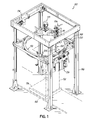
- FIG. 1 depicts a stretch wrapping apparatus 100 for wrapping a load 102 with packaging material 104 as depicted in FIGS. 10A-10D .
- the apparatus 100 may include an exemplary clamp assembly 106 having opposed first and second jaw members 108 and 110, each of which is movably mounted on a housing 112.
- the first and second jaw members 108 and 110 may lie substantially parallel with one another, and may be spaced from one another so as to receive the packaging material 104 therebetween.
- a length of each of the first and second jaw members 108 and 110 may be greater than an effective height (H) of the packaging material 104, the effective height (H) of the packaging material 104 corresponding to a distance between top and bottom edges of the packaging material 104 during wrapping of the load 102 as depicted in FIG. 6C .
- the first jaw member 108 and/or the second jaw member 110 may include low friction outer surfaces.
- the low friction outer surfaces may be made from a nonstick material, such as TeflonTM, or smooth metal, to minimize any undesirable frictional engagement between the outer surfaces and the packaging material 104.
- the first jaw member 108 and/or the second jaw member 110 may include low-friction panels (not shown) attached to their outer surfaces to minimize frictional engagement between the first and second jaw members 108 and 110 and the packaging material 104.
- the outer surfaces of the first jaw member 108 and/or the second jaw member 110 may be similar to the outer surfaces of jaw members described in U.S. Patent Application Publication No. 2009/0293435 .
- the first jaw member 108 may include a first inflatable bladder 114 defining a first material engaging surface 115.
- the first jaw member 108 may also include a first support 116, such as a formed channel or u-shaped bracket, having a cavity extending longitudinally along the first support 116 configured to receive at least a portion of the first inflatable bladder 114.
- the first support 116 may include any other suitable longitudinally extending recess, opening, or channel for receiving the first inflatable bladder 114. It is contemplated, for example, that the first inflatable bladder 114 may be secured on or in the first support 116 by a channel or cavity similar to that described in U.S. Patent Application Publication No. 2009/0293435 .
- the first inflatable bladder 114 may be mounted on or attached to a surface of the first support 116 without being received in a recess, cavity, or channel.
- the first inflatable bladder 114 may be attached to the first support 116 with adhesive, fasteners, and/or any other suitable attachment member.
- the first inflatable bladder 114 may be made of an elastomeric material, such as, for example, rubber.
- the first inflatable bladder 114 material may be selected based on its ability to frictionally engage the packaging material 104, as well as its ability to expand when pressurized. When the first inflatable bladder 114 is depressurized, it may cease to exert a force on the packaging material 104. Additionally or alternatively, when depressurized, the first inflatable bladder 114 may be contained within the first support 116 (i.e., may not extend beyond first support 116), out of contact with the packaging material 104.
- the first inflatable bladder 114 may extend longitudinally along the first jaw member 108 and may be sized to extend along the entire effective height (H) of the packaging material 104.
- the exact dimensions for the first inflatable bladder 114 may vary depending on a number of factors, such as, for example, the dimensions of the packaging material 104, the degree of clamping force desired, user preference, and/or other considerations.
- the first inflatable bladder 114 may be inflated using any suitable device (not shown) for delivering pressurizing fluid into the first bladder 114.
- the first inflatable bladder 114 may be pressurized via a reciprocating pump, a rotary pump, other suitable pressurizing devices known in the art, and any suitable combinations thereof.
- the pressurizing system may be positioned on any suitable supporting surface on the apparatus 100.
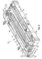
- the clamp assembly 106 may include a first actuation mechanism 118 configured to selectively actuate the first jaw member 108 such that the first jaw member 108 moves relative to the housing 112 between an extended position ( FIGS. 6A ), wherein the first jaw member 108 extends out from the housing 112, and a retracted position ( FIG. 4 ), wherein the first jaw member 108 is contained by the housing 112.
- the first actuation mechanism 118 may include, for example, a rodless cylinder, piston cylinder arrangement, pulley system, other motive systems known in the art, or any suitable combination thereof, and may be mounted on the housing 112.
- the clamp assembly 106 may also include a second actuation mechanism 120 configured to selectively actuate the second jaw member 110 such that the second jaw member 110 moves relative to the housing 112 between an extended position ( FIG. 7A ), where the second jaw member 110 extends out from the housing 112, and a retracted position ( FIG. 4 ), where the second jaw member 110 is contained by the housing 112. It should be understood that when the first and second jaw members 108 and 110 are both retracted, the first jaw member 108 is positioned adjacent the second jaw member 110 in the housing 112.
- the second actuation mechanism 120 may be similar to the first actuation mechanism 118, and may be mounted on the housing 112.
- first and second jaw members 108 and 110 may be independently extendable and retractable relative to each other, and/or extendable and retractable as a unit. Actuation of the first and second actuation mechanisms 118 and 120 may be triggered by a controller 122, as described in more detail below.
- the second jaw member 110 may include a second support 124 including, for example, a formed channel or C-shaped bracket.
- the second support 124 supports a belt assembly 126.
- the belt assembly 126 includes a fixed length belt 128 defining a second material engaging surface of the second jaw member 110.
- Belt 128 is supported on the second support 124 and routed around one or more bearings or pulleys 129. While the belt assembly 126 shown and described herein includes a fixed length belt 128, it will be appreciated that belt assembly 126 may alternatively include a looped or endless belt rotatably mounted on the second support 124.
- the arrangement of the belt 128 and the bearings or pulleys 129 may be similar to the arrangement described in U.S.
- the belt 128 may be at least partially received in a longitudinally extending recess, opening, or channel in the second support 124. It is also contemplated that at least a portion of the belt 128 faces the first inflatable bladder 114.
- the belt 128 may be movable relative to the second support 124, and may operate in a manner similar to the belt described in U.S. Patent No. 4,761,934 when clamping the packaging material 104. For example, when the first jaw member 108 is in its extended position and the second jaw member 110 is in its retracted position, at least a portion of the packaging material 104 may be wrapped over the side of the first jaw member 108 on which the first inflatable bladder 114 is positioned.
- the belt 128 of the second jaw member 110 may move with respect to the second support 124 by rotating around one or more of the bearings or pulleys 129 such that every portion of the belt 128 coming into contact with the packaging material 104 does not translate relative to the packaging material 104 after making contact with the packaging material 104. That is, the surface of the belt 128 opposing first bladder 114 may engage with packaging material 104, such that belt 128 "walks down" the clamped section of packaging material 104.
- Pressurizing the first inflatable bladder 114 may assist with clamping of the packaging material 104 between the first and second jaw members 108 and 110. For example, as pressure increases in the first inflatable bladder 114, the first inflatable bladder 114 may expand toward the second jaw member 110. Thus, a surface of the first inflatable bladder 114 may exert a clamping force on the packaging material 104 positioned between the surface of the inflatable bladder and the belt 128.
- Use of a bladder 114 overcomes a number of the prior art disadvantages. For example, using a bladder 114 eliminates the need for extremely tight tolerances in the space between the first and second jaw members 108 and 110 since the bladder 114 can dynamically account for space between first and second jaw members 108 and 110. Additionally, use of the bladder 114 improves distribution of the clamping force along the entire length of the first bladder 114. As such, the packaging material 104 may be evenly clamped between first and second jaw members 108 and 110.
- the packaging material 104 clamped between the first and second jaw members 108 and 110 may include an entirely flat portion of the packaging material 104, or alternatively, a portion of the packaging material 104 that is partially flat and partially roped or rolled into a cable.
- the portion of the packaging material 104 that is clamped may be similar to packaging material having a roped or rolled edge as described in U.S. Patent No. 7,779,607 B2 , U.S. Patent No. 7,568,327 , and/or U.S. Patent Application Publication No. 2007/0209324 .
- the roped or rolled portion of the packaging material 104 may include between approximately 3 to 5 inches of packaging material 104.
- any amount of packaging material to be held within the clamp assembly 106 as long as the clamp assembly 106 is capable of holding the packaging material 104 during start-up of a wrapping cycle, and preventing premature withdrawal of the packaging material 104 from the clamp assembly 106 under forces exerted on the packaging material 104 during the wrapping process. Nevertheless, for efficiency it is desirable to maintain as much of the effective height of the packaging material 104 as possible when clamping.
- the second jaw member 110 may also include a cutting device 130 and a sealing assembly 132.
- the cutting device 130 may be mounted proximate a cantilevered end of the second jaw member 110.
- the cutting device 130 may include, for example, a razor blade mounted on the second support 124 such that the razor blade travels alongside an edge of the first jaw member 108 when the first jaw member 108 is in its extended position and the second jaw member 110 is being moved to its extended position.
- the razor blade may have a sharp edge for cutting the packaging material 104 as the second jaw member 110 is extended.
- the cut may be made in the packaging material 104 along a portion of the packaging material 104 adjacent the portion held between the first inflatable bladder 114 of the first jaw member 108 and the belt 128 of the second jaw member 110.
- the cutting device 130 may be similar to the blade described in U.S. Patent No. 4,761,934 .
- the cutting device 130 may include a hot wire (not shown) extending along the height of at least one of the first and second jaw members 108 and 110.
- the hot wire may be heated for cutting the packaging material 104.
- one side of the packaging material 104 the side that extends to the load 102, may become a trailing end 134, while the other side of the packaging material 104, the side that extends to a packaging material dispenser 136, may become a new leading end 138.
- the new leading end 138 of packaging material 104 remains clamped between the first and second jaw members 108 and 110, in preparation for wrapping a subsequent load.
- the sealing assembly 132 may also be coupled to the second jaw member 110, and may be configured to press or seal the trailing end 134 against a wrapped load surface subsequent to cutting of the packaging material 104. As shown and embodied in FIGS. 2-4 , 6A-6C , 7A-7B , and 8 , the sealing assembly 132 may include one or more pressing belts 140. For example, the sealing assembly 132 may include three pressing belts 140, It is to be understood that any number of pressing belts 140 sufficient to seal down packaging material 104 may be used.
- the pressing belts 140 may be made of a flexible plastic, such as, for example, polyethylene. Alternatively, any suitable flexible material may be used.
- the pressing belts 140 may be mounted in a recess, opening, or channel, such as the one shown in the second support 124.
- the pressing belts 140 may be rotatably mounted on the second jaw member 110 by one or more bearings or pulleys, such as, for example, pulleys 142 and 144.
- the pressing belts 140 may be movable relative to the second support 124, and may operate in a manner similar to the belt 128 and the belt described in U.S. Patent No. 4,761,934 .
- the packaging material 104 may be wrapped over the side of the first jaw member 108 on which the first inflatable bladder 114 is positioned.
- the cutting device 130 cuts the packaging material 104 to form the leading end 138 and the trailing end 134, and the pressing belts 140 may press the trailing end 134 against the wrapped load surface.
- the pressing belts 140 may move with respect to the second support 124 by rotating around the pulleys 142 and 144 such that at least portions of the pressing belts 140 contacting the trailing end 134 do not translate relative to the trailing end 134 after making contact.
- the pressing belts 140 help maintain the trailing end 134 of the packaging material 104 in a substantially flat orientation, with little or no reduction in its effective height, while also pressing the trailing end 134 against the wrapped load 102 surface. Because the trailing end 134 undergoes substantially no reduction to its effective height, the trailing end 134 adheres easily to the wrapped load 102 surface. It is contemplated that sealing of the trailing end 134 against the wrapped load surface, clamping, and cutting all occur in one smooth operation during extension of the second jaw member 110.
- the clamp assembly 106 may be coupled to a non-rotating frame 146 by a support assembly such as a swing-arm assembly 148, such that the clamp assembly 106 is cantilevered from the non-rotating frame 146 by the swing-arm assembly 148.
- the first and second jaw members 108 and 110 when extended, may be further cantilevered from the housing 112.
- the swing-arm assembly 148 may include one or more linkages 150 configured to move the clamp assembly 106 between a first radially outward position spaced apart from a surface of the load 102, and a second radially inward position contacting the surface of the load 102, as illustrated generally in FIG. 9 .
- the linkages 150 may be arranged in a parallelogram form, with the different linkages rotatably coupled at their ends by pivot points.
- the pivot points allow the parallelogram formed by the linkages 150 to contract and expand when moving the clamp assembly 106 between the first and second positions.
- the contraction and expansion of the parallelogram creates a path of movement for the clamp assembly 106 that is substantially linear as the clamp assembly 106 moves toward and away from a surface of the load 102.
- the swing-arm assembly 148 may include any other structure suitable for supporting and moving the clamp assembly 106, such as a bar, a frame, a wire structure, a telescoping element, or a truss.
- the swing-arm assembly 148 may include any appropriate deployment mechanism (not shown), such as, for example, a hydraulic pressure cylinder, a pneumatic pressure cylinder, and/or solenoid actuator, configured to move the swing-arm assembly 148, and in turn, move the clamp assembly 106 between its first and second positions.
- the deployment mechanism may be controlled by the controller 122 ( FIG. 9 ).
- the controller 122 may actuate the deployment mechanism at a desired time during the wrap cycle to move the clamp assembly 106 toward the load 102 or away from the load 102.
- a sensing assembly 152 may be provided on the first jaw member 108.
- the sensing assembly 152 may be configured to sense a position of the clamp assembly 106 relative to the load 102.
- the sensing assembly 152 may include an elongated bar or plate 154 whose top end is attached to a top end of the first jaw member 108 by a pivot or bearing 156 proximate the top end of the first jaw member 108.
- the elongated bar 154 may include a slot 158 near its bottom end configured to receive a post 160 on the first jaw member 108.
- the post 160 may extend from the first support 116 of the first jaw member 108.
- the elongated bar 154 may be spring-biased such that a lower portion of the elongated bar 154 extends away from the first jaw member 108 and toward the load 102 in the absence of a counteracting force.
- a sensor 164 such as a position sensor, laser sensor, photodetector, or any other suitable sensor device, may monitor the position of a portion of the elongated bar 154.
- sensor 164 may send a position signal to a controller 122 that controls actuation of the deployment mechanism that moves the swing-arm assembly 148 and the clamp assembly 106.
- the controller 122 may output a stop command to the deployment mechanism when the position signal indicates that the clamp assembly 106 has reached a desired position relative to the surface of the load 102.
- the sensing assembly 152 prevents the clamp assembly 106 from being damaged by being pressed against the load 102 with excessive force, and also prevents the clamp assembly 106 from causing an undesired shifting of the load 102, or from damaging the load 102 or layers of packaging material 104 wrapped thereon.
- FIG. 8A depicts another exemplary clamp assembly 106a having a second jaw member 110a, similar to the second jaw member 110 shown and described above with respect to FIGS. 2-5 and 6A-6C .
- the second jaw member 110a includes a second inflatable bladder 166.
- the second inflatable bladder 166 may be similar to the first inflatable bladder 114 on the first jaw member 108 in form and operation, and also similar to the bladder in U.S. Patent Application Publication No. 2009/0293435 .
- Any appropriate device for pressurizing the second inflatable bladder 166 may be employed, including, for example, a reciprocating pump, a rotary pump, other pressurizing systems known in the art, and any suitable combinations thereof.
- the pressurizing system may be positioned on the second jaw member 110a, the housing 112, the clamp swing-arm assembly 148, or any other appropriate location on apparatus 100.
- the second inflatable bladder 166 may be mounted in a recess, opening, or channel, such as the cavity shown in second support 124 of the second jaw member 110a. Alternatively, the second inflatable bladder 166 may be mounted on or attached to a surface of the second jaw member 110a without being received in a cavity. For example, the second inflatable bladder 166 may be attached to the second jaw member 110a with adhesive, brackets, fasteners, and/or any other suitable attachment member.
- the second inflatable bladder 166 may be positioned under the belt 128. That is, the second inflatable bladder 166 may be disposed between a surface of the second support 124 and the belt 128. In other words, the second inflatable bladder 166 may be disposed in contact with a surface of the belt 128 that does not contact the packaging material 104. Accordingly, when the second inflatable bladder 166 is pressurized, the belt 128 may be urged toward the first inflatable bladder 144, thus enhancing the clamping force exerted on the packaging material 104 by the belt 128 and the first inflatable bladder 114.
- the second inflatable bladder 166 When the second inflatable bladder 166 is depressurized, it may cease to urge the belt 128 against the packaging material 104. Additionally or alternatively, when the second inflatable bladder 166 is depressurized, the second inflatable bladder 166 may be contained within the second support 124 (i.e., may not extend beyond the second support 124).
- apparatus 100 is configured to wrap the packaging material 104 around the load 102.
- the apparatus 100 includes the nonrotating frame 146 ( FIG. 1 ) defining a wrapping space.
- the load 102 may be conveyed by a conveyor 168 into the wrapping space prior to wrapping, and out of the wrapping space subsequent to wrapping.
- the conveyor 168 may include a conveyor belt having either powered or unpowered rollers, or a drag-chain conveyor.
- the packaging material dispenser 136 is provided such that it dispenses the packaging material 104.
- the packaging material dispenser 136 may include a prestretch assembly for pre-stretching the packaging material 104 before it is applied on the load 102.
- the apparatus 100 may also include a relative rotation assembly 170 for providing relative rotation between the packaging material dispenser 136 and the load 102.
- the relative rotation assembly 170 may include, for example, a rotating arm, a rotatable turntable, or a rotating ring 172 shown in FIG. 1 .
- the apparatus 100 also includes a vertical drive assembly 174 for providing relative movement between the packaging material dispenser 136 and the load 102 in a vertical direction, along the axis of rotation of the packaging material dispenser 136 relative to the load 102.
- the relative rotation between the packaging material dispenser 136 and the load 102 in combination with the relative vertical movement of the packaging material dispenser 136 relative to the load 102, may serve to wrap the packaging material 104 spirally around the load 102 and a pallet 176 supporting the load 102.
- the packaging material dispenser 136, relative rotation assembly 170, and vertical drive assembly 174 may be similar to those described in U.S. Patent No. 7,779,607 B2 , U.S. Patent No. 7,707,801 , and/or U.S. Patent Application Publication No. 2009/0178374 .
- a method of wrapping the load 102 with the packaging material 104 using the apparatus 100 may include positioning the load 102 to be wrapped in the wrapping space of the apparatus 100 using, for example, the conveyor 168.
- the swing-arm assembly 148 may hold the clamp assembly 106 in the radially outward position to prevent interference between the load 102 and the clamp assembly 106.
- the first and second jaw members 108 and 110 may be in their extended positions, and may hold a leading end 138 of the packaging material 104 therebetween.
- the first inflatable bladder 114 may be pressurized, and may exert a clamping force on the leading end 138 of the packaging material 104 by urging it against the belt 128. If the second jaw 110a is being used, the second inflatable bladder 166 may also be pressurized to urge the belt 128 toward the first inflatable bladder 114, thus further enhancing the clamping force on the leading end 138.
- the clamp assembly 106 is moved toward a surface of the load 102 (i.e., towards the second radially inward position of the clamp assembly 106) by movement of the swing-arm assembly 148. This movement may bring the first and second jaw members 108 and 110, as well as the leading end 138 clamped therebetween, proximate the load 102. At some point, the elongated bar 154 may be brought into contact with the surface of the load 102 and may begin to move.
- the controller 122 When the sensor 164 senses that movement of the elongated bar 154 has reached a threshold indicative of the clamp assembly 106 having reached a desired position relative to the surface of the load 102, the controller 122 outputs a stop command to the deployment mechanism moving the swing-arm assembly 148.
- Relative rotation may be provided between the load 102 and the packaging material dispenser 136 to wrap the packaging material 104 around the load 102.
- the packaging material 104 is wrapped over the first and second jaw members 108 and 110 that are positioned proximate the load 102.
- the first inflatable bladder 114 and/or the second inflatable bladder 166 may be depressurized to cease clamping of the leading end 138 of the packaging material 104.
- the first and second jaw members 108 and 110 may be retracted and raised out of the packaging material dispensing path.
- depressurization of the first inflatable bladder 114 and/or the second inflatable bladder 166, and/or retraction of the first and second jaw members 108 and 110 may occur just prior to being overwrapped by the packaging material 104.
- the first and second jaw members 108 and 110 may be retracted substantially simultaneously or in any suitable order.
- the first and second jaw members 108 and 110 may be raised through actuation of the first and second actuation mechanisms 118 and 120, which may be controlled by the controller 122. Once the first and second jaw members 108 and 110 have been raised, the leading end 138 may be held in place by the overwrapped layers of the packaging material 104. Moreover, elastic recovery in the overwrapped layers may cause the layers to snap back toward the load 102, thus securing the leading end 138. With the first and second jaw members 108 and 110 free of the packaging material 104, the controller 122 may actuate the swing-arm assembly 148 to move the clamp assembly 106 away from load 102 (i.e., towards its first radially outward position).
- the packaging material dispenser 136 may continue to dispense packaging material 104 to load 102 in a spiral fashion, as described in U.S. Patent No. 7,779,607 .
- the first jaw member 108 may be extended and, along with the rest of the clamp assembly 106, may be moved toward the wrapped surface of the load 102 (i.e., toward its first radially inward position) by the swinging of the swing-arm assembly 148.
- the controller 122 stops moving the clamp assembly 106 toward the wrapped surface of the load 102 when the sensor 164 and the elongated bar 154 indicate that the desired position has been reached.
- At least one layer of the packaging material 104 may be wrapped over the first jaw member 108.
- the first inflatable bladder 114 may be pressurized at this time. Alternatively, the first inflatable bladder 114 may remain unpressurized.
- the second jaw member 110 is actuated to move to its extended position substantially parallel to and adjacent the first jaw member 108.
- the belt 128 may engage the packaging material 104, pressing the packaging material 104 against the first inflatable bladder 114.
- the cutting device 130 also begins cutting the packaging material 104 as the second jaw member 110 extends, creating a new leading end portion 138 on the side of the cut with the packaging material 104 that is held by the jaw members 108 and 110, and a new trailing end portion 134 on the side of the cut with the packaging material 104 that extends to the wrapped load 102.
- the pressing belts 140 begin to engage the new trailing end portion 134 by pressing or sealing the new trailing end portion 134 against the wrapped load 102 surface. Continued extension of the second jaw member 110 brings continued clamping, cutting, and sealing. If the first inflatable bladder 114 has not been pressurized, it may be pressurized during extension of the second jaw member 110, or after extension, to assist with clamping.
- Engagement of the belt 128 with the packaging material 104 helps to maintain the leading end 138 of the packaging material 104 in a relatively flat position as the second jaw member 110 is extended and the packaging material 104 is cut by the cutting device 130. Because the packaging material 104 is held relatively flat, its effective height is not reduced as would be the case if the packaging material 104 was collapsed into a rope or cable, thus providing for more efficient use of the packaging material 104. Engagement of the pressing belts 140 with the packaging material 104 helps to press or seal the trailing end 134 of the packaging material 104 against the wrapped load surface with little or no reduction in the effective height of the trailing end 134, thus providing for better adherence between the trailing end 140 and the layers of the packaging material 104 on the load 102.
- the controller 122 moves the swing-arm assembly 148 away from the wrapped load 102, bringing the extended first and second jaw members 108 and 110 away from the wrapped load 102.
- both the first and second jaw members 108 and 110 remain extended, and continue clamping the leading end 138, maintaining the leading end 138 in place.
- Moving the first and second jaw members 108 and 110 gets them out of the way of the wrapped load 102 as the wrapped load 102 is conveyed out of the wrapping area by the conveyor 168.
- a new unwrapped load 102 may then be conveyed into the wrapping area, and the method may repeat for another wrap cycle.
Landscapes
- Engineering & Computer Science (AREA)
- Mechanical Engineering (AREA)
- Basic Packing Technique (AREA)
Description
- This application claims the filing benefit of
U.S. Provisional Patent Application Serial No. 61/408,541 filed on October 29, 2010 - This disclosure relates generally to methods and apparatus for wrapping a load with packaging material, and more particularly, to methods and apparatus for clamping packaging material.
- Loads have been wrapped with packaging material by dispensing the packaging material with a packaging material dispenser, and providing relative rotation between the load and the packaging material dispenser to cover the load with the packaging material. Semi-automatic wrapping machines exist that require attachment of a leading end portion of the packaging material to the load by an operator prior to wrapping of the load. This is typically accomplished by collapsing the leading end portion into a rope, and then inserting the rope between layers of the load or tying the rope to an edge of a pallet or any suitable outcropping on the load. This attachment must be strong enough to resist a pulling force exerted by the packaging material dispenser on the packaging material during initiation of the relative rotation between the load and the packaging material dispenser. This type of attachment makes removing the packaging material difficult after the load has been shipped to its destination and is being unwrapped. Further, throughput is decreased due to the operator having to attach the leading end portion of the packaging material to each load before wrapping the load. Additionally, collapsing the leading end portion of the packaging material reduces its effective height, thus requiring the use of more packaging material to adequately cover the load.
- Automatic wrapping machines typically use packaging material clamps that grip the packaging material between two opposed surfaces and use electrical or pneumatic actuators to open and close the clamps. Such packaging material clamps may be overwrapped by the packaging material during wrapping, and may create a "tenting" effect due to their distance from the load, resulting in wasted packaging material and loosely wrapped loads. Additionally, such clamps are expensive and may require costly maintenance for the electrical and mechanical actuators. Furthermore, such clamps tend to collapse the packaging material or require collapsing of the packaging material prior to clamping, thus reducing the effective height of the packaging material.
- Other machines use a vacuum device that uses suction to hold the packaging material. This typically requires that the packaging material be placed in a flat manner against the vacuum device so that the vacuum device can provide its full gripping force on the packaging material. Flat placement of the packaging material is difficult to achieve. Also, the vacuum device may damage the packaging material if the suction generated is too high, while the packaging material may be pulled off the vacuum device if the suction is too low. Furthermore, the vacuum device may have difficulty gripping a roped portion of the packaging material, where the strength of the packaging material is concentrated.
-
US 4,761,934 B discloses a clamp for clamping a web during stretch wrapping which includes a first longitudinally extending clamp element for engaging the web, a second longitudinally extending clamp element extendable in a direction generally parallel to the longitudinal direction of the first clamp element for clamping the web between the second clamp element and the first clamp element as the second clamp element is longitudinally extending in a direction parallel to the longitudinal direction of the first clamp element. - The present disclosure is directed to overcoming one or more of the above-noted problems.
- According to an aspect of the present disclosure, a clamp assembly may include a first jaw member which may have a selectively inflatable bladder. In addition, the clamp assembly may further include a second jaw member which may have a belt. The first jaw member and the second jaw member may be configured to clamp material between the selectively inflatable bladder and the belt.
- According to another aspect of the present disclosure, a method of clamping packaging material with a clamp assembly which may have a first jaw member including a selectively inflatable bladder and a second jaw member which may have a belt may include moving the first jaw member into engagement with the packaging material. The method may further include inflating the inflatable bladder against a first surface of the packaging material and moving the second jaw member relative to the first jaw member while engaging a second surface of the packaging material opposite the first surface with the belt. Additionally, the method may include moving the belt relative to the second jaw member such that after a portion of the belt contacts a portion of the packaging material, the portion of the belt may remain fixed relative to the portion of the packaging material as the second jaw member moves relative to the first jaw member. The method may further include clamping the packaging material between the inflatable bladder and the belt without reducing a height of the packaging material.
- According to yet another aspect of the present disclosure, a packaging material clamp assembly may include a first longitudinally extending jaw member which may have a selectively expandable bladder, and a second longitudinally extending jaw member which may have a belt opposed to the selectively expandable bladder. In addition, the first and second longitudinally extending jaw members may be configured to clamp packaging material between the selectively expandable bladder and the belt.
- According to yet another aspect of the present disclosure, an apparatus for wrapping a load with packaging material may include a packaging material dispenser which may be configured to dispense packaging material to the load. In addition, the apparatus may include a relative rotation assembly which may be configured to provide relative rotation between the packaging material dispenser and the load. Also, the apparatus may include a clamp assembly which may have a first longitudinally extending jaw member including a selectively expandable bladder and a second longitudinally extending jaw member including a belt opposed to the selectively expandable bladder. The first and second longitudinally extending jaw members may be configured to clamp the packaging material between the selectively expandable bladder and the belt.
- According to yet another aspect of the present disclosure, a method for wrapping a load with packaging material may include positioning the load in a position to be wrapped, providing relative rotation between a packaging material dispenser and the load while the packaging material dispenser dispenses the packaging material, and extending a first longitudinally extending jaw member into a path of the dispensed packaging material, wherein the first longitudinally extending jaw member may include a selectively expandable bladder thereon. In addition, the method may include overwrapping the first longitudinally extending jaw member with packaging material such that the packaging material is adjacent the selectively expandable bladder, and extending a second longitudinally extending jaw member alongside the first longitudinally extending jaw member, wherein the second longitudinally extending jaw member may include a belt rotatably mounted thereon. Further, the method may include contacting the packaging material with the belt while moving the belt to maintain at least a portion of the belt fixed relative to the selectively expandable bladder to clamp the packaging material between the belt and the selectively expandable bladder as the second longitudinally extending jaw member is extended.
- According to yet another aspect of the present disclosure, a clamp assembly may include a first jaw member including a selectively inflatable bladder with a first material engaging surface. The clamp assembly may also include a second jaw member including a second material engaging surface. The second jaw member may be movable relative to the first jaw member along a longitudinal axis of the second jaw member. The first jaw member and the second jaw member may be configured to clamp material between the first material engaging surface and the second material engaging surface.
- Additional aspects and advantages of the disclosure will be set forth in the description which follows, and in part will be apparent from the description, or may be learned by practice of the disclosure. The aspects and other advantages of the disclosure will be realized and attained by the methods and apparatuses particularly pointed out in the written description and claims as well as the appended drawings.
- It is to be understood that both the foregoing general description and the following detailed description are exemplary and explanatory and are intended to provide further explanation of the disclosure as claimed.
- The accompanying drawings provide a further understanding of the disclosure and are incorporated in and constitute a part of the specification, illustrate embodiments of the disclosure and together with the description serve to explain the principles of the disclosure.
-
-
FIG. 1 is a perspective view of a stretch wrapping apparatus including an exemplary clamp assembly in accordance with an aspect of the present disclosure. -
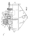
FIG. 2 is a top view of the clamp assembly ofFIG. 1 . -
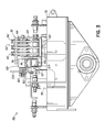
FIG. 3 is a bottom view of the clamp assembly ofFIG. 1 . -
FIG. 4 is a perspective view of the clamp assembly ofFIG. 1 , according to an aspect of the present disclosure. -
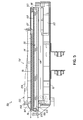
FIG. 5 is a cross-sectional view of the exemplary clamp assembly ofFIG. 4 , taken along line 5-5. -
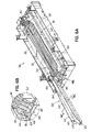
FIG. 6A is a perspective view of the clamp assembly ofFIG. 4 , with a first jaw in an extended position. -
FIG. 6B is an enlarged view of the encircled portion ofFIG. 6A . -
FIG. 6C is a perspective view, similar toFIG. 6A , illustrating engagement of the first jaw with packaging material. -
FIG. 7A is a perspective view of the clamp assembly ofFIG. 4 , similar toFIG. 6A , with first and second jaws in extended positions. -
FIG. 7B is an enlarged view of the encircled portion ofFIG. 7A . -
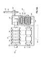
FIG. 8 is a cross-sectional view of the clamp assembly ofFIG. 4 , taken along line 8-8. -
FIG. 8A is a cross-sectional view, similar toFIG. 8 , of another exemplary clamp assembly in accordance with an aspect of the present disclosure. -
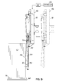
FIG. 9 is a partial elevation view of the clamp assembly ofFIG. 1 , illustrating a sensing assembly in accordance with an aspect of the present disclosure. -
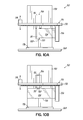
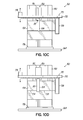
FIGS. 10A-10D are schematic drawings illustrating stages of a wrapping cycle, in accordance with an aspect of the present disclosure. - Reference will now be made to the present embodiments of the disclosure, examples of which are illustrated in the accompanying drawings. Wherever possible, the same reference numbers will be used throughout the drawings to refer to the same or like parts. The disclosures of each of:
U.S. Patent No. 4,761,934 , entitled "PARALLEL BELTED CLAMP," issued August 9, 1988;U.S. Patent No. 7,779,607 , entitled "WRAPPING APPARATUS INCLUDING METERED PRE-STRETCH FILM DELIVERY ASSEMBLY AND METHOD OF USING," issued August 24,2010;U.S. Patent Application Publication No. 2009/0293435 entitled "FILM CLAMP AND RELATED METHODS AND APPARATUSES FOR WRAPPING LOADS," published December 3, 2009;U.S. Patent No. 7,568,327 , entitled "METHOD AND APPARATUS FOR SECURING A LOAD TO A PALLET WITH A ROPED FILM WEB," filed January 30, 2004;U.S. Patent No. 7,707,801 , entitled "METHOD FOR DISPENSING A PREDETERMINED AMOUNT OF FILM RELATIVE TO LOAD GIRTH," filed April 6, 2006;U.S. Patent Application Publication No. 2009/0178374 , entitled "ELECTRONIC CONTROL OF METERED FILM DISPENSING IN A WRAPPING APPARATUS," filed January 7, 2009; andU.S. Patent Application Publication No. 2007/0209324 , entitled "METHOD AND APPARATUS FOR SECURING A LOAD TO A PALLET WITH A ROPED FILM WEB," filed February 23, 2007, are incorporated herein by reference in their entirety. -
FIG. 1 depicts astretch wrapping apparatus 100 for wrapping aload 102 withpackaging material 104 as depicted inFIGS. 10A-10D . Theapparatus 100 may include anexemplary clamp assembly 106 having opposed first andsecond jaw members housing 112. The first andsecond jaw members packaging material 104 therebetween. A length of each of the first andsecond jaw members packaging material 104, the effective height (H) of thepackaging material 104 corresponding to a distance between top and bottom edges of thepackaging material 104 during wrapping of theload 102 as depicted inFIG. 6C . - The
first jaw member 108 and/or thesecond jaw member 110 may include low friction outer surfaces. The low friction outer surfaces may be made from a nonstick material, such as Teflon™, or smooth metal, to minimize any undesirable frictional engagement between the outer surfaces and thepackaging material 104. Additionally or alternatively, thefirst jaw member 108 and/or thesecond jaw member 110 may include low-friction panels (not shown) attached to their outer surfaces to minimize frictional engagement between the first andsecond jaw members packaging material 104. For example, the outer surfaces of thefirst jaw member 108 and/or thesecond jaw member 110 may be similar to the outer surfaces of jaw members described inU.S. Patent Application Publication No. 2009/0293435 . - As shown in
FIGS. 2-5 , and8 , thefirst jaw member 108 may include a firstinflatable bladder 114 defining a firstmaterial engaging surface 115. Thefirst jaw member 108 may also include afirst support 116, such as a formed channel or u-shaped bracket, having a cavity extending longitudinally along thefirst support 116 configured to receive at least a portion of the firstinflatable bladder 114. Additionally or alternatively, thefirst support 116 may include any other suitable longitudinally extending recess, opening, or channel for receiving the firstinflatable bladder 114. It is contemplated, for example, that the firstinflatable bladder 114 may be secured on or in thefirst support 116 by a channel or cavity similar to that described inU.S. Patent Application Publication No. 2009/0293435 . Alternatively, the firstinflatable bladder 114 may be mounted on or attached to a surface of thefirst support 116 without being received in a recess, cavity, or channel. For example, the firstinflatable bladder 114 may be attached to thefirst support 116 with adhesive, fasteners, and/or any other suitable attachment member. - The first
inflatable bladder 114 may be made of an elastomeric material, such as, for example, rubber. The firstinflatable bladder 114 material may be selected based on its ability to frictionally engage thepackaging material 104, as well as its ability to expand when pressurized. When the firstinflatable bladder 114 is depressurized, it may cease to exert a force on thepackaging material 104. Additionally or alternatively, when depressurized, the firstinflatable bladder 114 may be contained within the first support 116 (i.e., may not extend beyond first support 116), out of contact with thepackaging material 104. - The first
inflatable bladder 114 may extend longitudinally along thefirst jaw member 108 and may be sized to extend along the entire effective height (H) of thepackaging material 104. The exact dimensions for the firstinflatable bladder 114 may vary depending on a number of factors, such as, for example, the dimensions of thepackaging material 104, the degree of clamping force desired, user preference, and/or other considerations. - The first
inflatable bladder 114 may be inflated using any suitable device (not shown) for delivering pressurizing fluid into thefirst bladder 114. For example, the firstinflatable bladder 114 may be pressurized via a reciprocating pump, a rotary pump, other suitable pressurizing devices known in the art, and any suitable combinations thereof. The pressurizing system may be positioned on any suitable supporting surface on theapparatus 100. - As shown in
FIGS. 2-5 ,6A , and6C , theclamp assembly 106 may include afirst actuation mechanism 118 configured to selectively actuate thefirst jaw member 108 such that thefirst jaw member 108 moves relative to thehousing 112 between an extended position (FIGS. 6A ), wherein thefirst jaw member 108 extends out from thehousing 112, and a retracted position (FIG. 4 ), wherein thefirst jaw member 108 is contained by thehousing 112. Thefirst actuation mechanism 118 may include, for example, a rodless cylinder, piston cylinder arrangement, pulley system, other motive systems known in the art, or any suitable combination thereof, and may be mounted on thehousing 112. - The
clamp assembly 106 may also include asecond actuation mechanism 120 configured to selectively actuate thesecond jaw member 110 such that thesecond jaw member 110 moves relative to thehousing 112 between an extended position (FIG. 7A ), where thesecond jaw member 110 extends out from thehousing 112, and a retracted position (FIG. 4 ), where thesecond jaw member 110 is contained by thehousing 112. It should be understood that when the first andsecond jaw members first jaw member 108 is positioned adjacent thesecond jaw member 110 in thehousing 112. Thesecond actuation mechanism 120 may be similar to thefirst actuation mechanism 118, and may be mounted on thehousing 112. It is contemplated that the first andsecond jaw members second actuation mechanisms controller 122, as described in more detail below. - As shown in
FIGS. 2-5 and8 , thesecond jaw member 110 may include asecond support 124 including, for example, a formed channel or C-shaped bracket. Thesecond support 124 supports abelt assembly 126. Thebelt assembly 126 includes a fixedlength belt 128 defining a second material engaging surface of thesecond jaw member 110.Belt 128 is supported on thesecond support 124 and routed around one or more bearings or pulleys 129. While thebelt assembly 126 shown and described herein includes a fixedlength belt 128, it will be appreciated thatbelt assembly 126 may alternatively include a looped or endless belt rotatably mounted on thesecond support 124. The arrangement of thebelt 128 and the bearings or pulleys 129 may be similar to the arrangement described inU.S. Patent No. 4,761,934 . It is contemplated that thebelt 128 may be at least partially received in a longitudinally extending recess, opening, or channel in thesecond support 124. It is also contemplated that at least a portion of thebelt 128 faces the firstinflatable bladder 114. - The
belt 128 may be movable relative to thesecond support 124, and may operate in a manner similar to the belt described inU.S. Patent No. 4,761,934 when clamping thepackaging material 104. For example, when thefirst jaw member 108 is in its extended position and thesecond jaw member 110 is in its retracted position, at least a portion of thepackaging material 104 may be wrapped over the side of thefirst jaw member 108 on which the firstinflatable bladder 114 is positioned. When thesecond jaw member 110 is moved to its extended position to clamp thepackaging material 104 in conjunction with thefirst jaw member 108, thebelt 128 of thesecond jaw member 110 may move with respect to thesecond support 124 by rotating around one or more of the bearings or pulleys 129 such that every portion of thebelt 128 coming into contact with thepackaging material 104 does not translate relative to thepackaging material 104 after making contact with thepackaging material 104. That is, the surface of thebelt 128 opposingfirst bladder 114 may engage withpackaging material 104, such thatbelt 128 "walks down" the clamped section ofpackaging material 104. This allows thepackaging material 104 to be held between thefirst jaw member 108 and thesecond jaw member 110 when thejaw members packaging material 104 clamped between the first andsecond jaw members - Pressurizing the first
inflatable bladder 114 may assist with clamping of thepackaging material 104 between the first andsecond jaw members inflatable bladder 114, the firstinflatable bladder 114 may expand toward thesecond jaw member 110. Thus, a surface of the firstinflatable bladder 114 may exert a clamping force on thepackaging material 104 positioned between the surface of the inflatable bladder and thebelt 128. Use of abladder 114 overcomes a number of the prior art disadvantages. For example, using abladder 114 eliminates the need for extremely tight tolerances in the space between the first andsecond jaw members bladder 114 can dynamically account for space between first andsecond jaw members bladder 114 improves distribution of the clamping force along the entire length of thefirst bladder 114. As such, thepackaging material 104 may be evenly clamped between first andsecond jaw members - The
packaging material 104 clamped between the first andsecond jaw members packaging material 104, or alternatively, a portion of thepackaging material 104 that is partially flat and partially roped or rolled into a cable. For example, the portion of thepackaging material 104 that is clamped may be similar to packaging material having a roped or rolled edge as described inU.S. Patent No. 7,779,607 B2 ,U.S. Patent No. 7,568,327 , and/orU.S. Patent Application Publication No. 2007/0209324 . It is contemplated that in one embodiment, the roped or rolled portion of thepackaging material 104 may include between approximately 3 to 5 inches ofpackaging material 104. However, it is possible for any amount of packaging material to be held within theclamp assembly 106 as long as theclamp assembly 106 is capable of holding thepackaging material 104 during start-up of a wrapping cycle, and preventing premature withdrawal of thepackaging material 104 from theclamp assembly 106 under forces exerted on thepackaging material 104 during the wrapping process. Nevertheless, for efficiency it is desirable to maintain as much of the effective height of thepackaging material 104 as possible when clamping. - As shown in
FIGS. 6B and7B , thesecond jaw member 110 may also include acutting device 130 and a sealingassembly 132. Thecutting device 130 may be mounted proximate a cantilevered end of thesecond jaw member 110. Thecutting device 130 may include, for example, a razor blade mounted on thesecond support 124 such that the razor blade travels alongside an edge of thefirst jaw member 108 when thefirst jaw member 108 is in its extended position and thesecond jaw member 110 is being moved to its extended position. The razor blade may have a sharp edge for cutting thepackaging material 104 as thesecond jaw member 110 is extended. The cut may be made in thepackaging material 104 along a portion of thepackaging material 104 adjacent the portion held between the firstinflatable bladder 114 of thefirst jaw member 108 and thebelt 128 of thesecond jaw member 110. For example, thecutting device 130 may be similar to the blade described inU.S. Patent No. 4,761,934 . - Additionally or alternatively, it is contemplated that the
cutting device 130 may include a hot wire (not shown) extending along the height of at least one of the first andsecond jaw members packaging material 104. - When the
cutting device 130 cuts thepackaging material 104, one side of thepackaging material 104, the side that extends to theload 102, may become a trailingend 134, while the other side of thepackaging material 104, the side that extends to apackaging material dispenser 136, may become a newleading end 138. As shown inFIG. 10D , after the cutting step, the newleading end 138 ofpackaging material 104 remains clamped between the first andsecond jaw members - The sealing
assembly 132 may also be coupled to thesecond jaw member 110, and may be configured to press or seal the trailingend 134 against a wrapped load surface subsequent to cutting of thepackaging material 104. As shown and embodied inFIGS. 2-4 ,6A-6C ,7A-7B , and8 , the sealingassembly 132 may include one or morepressing belts 140. For example, the sealingassembly 132 may include threepressing belts 140, It is to be understood that any number ofpressing belts 140 sufficient to seal downpackaging material 104 may be used. Thepressing belts 140 may be made of a flexible plastic, such as, for example, polyethylene. Alternatively, any suitable flexible material may be used. - At least a portion of the
pressing belts 140 may be mounted in a recess, opening, or channel, such as the one shown in thesecond support 124. Thepressing belts 140 may be rotatably mounted on thesecond jaw member 110 by one or more bearings or pulleys, such as, for example, pulleys 142 and 144. Thepressing belts 140 may be movable relative to thesecond support 124, and may operate in a manner similar to thebelt 128 and the belt described inU.S. Patent No. 4,761,934 . For example, when thefirst jaw member 108 is in its extended position and thesecond jaw member 110 is in its retracted position, at least a portion of thepackaging material 104 may be wrapped over the side of thefirst jaw member 108 on which the firstinflatable bladder 114 is positioned. When thesecond jaw member 110 is moved to its extended position thecutting device 130 cuts thepackaging material 104 to form theleading end 138 and the trailingend 134, and thepressing belts 140 may press the trailingend 134 against the wrapped load surface. As thepressing belts 140 engage the trailingend 134, thepressing belts 140 may move with respect to thesecond support 124 by rotating around thepulleys pressing belts 140 contacting the trailingend 134 do not translate relative to the trailingend 134 after making contact. Thus, thepressing belts 140 help maintain the trailingend 134 of thepackaging material 104 in a substantially flat orientation, with little or no reduction in its effective height, while also pressing the trailingend 134 against the wrappedload 102 surface. Because the trailingend 134 undergoes substantially no reduction to its effective height, the trailingend 134 adheres easily to the wrappedload 102 surface. It is contemplated that sealing of the trailingend 134 against the wrapped load surface, clamping, and cutting all occur in one smooth operation during extension of thesecond jaw member 110. - As shown in
FIG. 1 , theclamp assembly 106 may be coupled to anon-rotating frame 146 by a support assembly such as a swing-arm assembly 148, such that theclamp assembly 106 is cantilevered from thenon-rotating frame 146 by the swing-arm assembly 148. The first andsecond jaw members housing 112. The swing-arm assembly 148 may include one ormore linkages 150 configured to move theclamp assembly 106 between a first radially outward position spaced apart from a surface of theload 102, and a second radially inward position contacting the surface of theload 102, as illustrated generally inFIG. 9 . - The
linkages 150 may be arranged in a parallelogram form, with the different linkages rotatably coupled at their ends by pivot points. The pivot points allow the parallelogram formed by thelinkages 150 to contract and expand when moving theclamp assembly 106 between the first and second positions. The contraction and expansion of the parallelogram creates a path of movement for theclamp assembly 106 that is substantially linear as theclamp assembly 106 moves toward and away from a surface of theload 102. Alternatively, the swing-arm assembly 148 may include any other structure suitable for supporting and moving theclamp assembly 106, such as a bar, a frame, a wire structure, a telescoping element, or a truss. The swing-arm assembly 148 may include any appropriate deployment mechanism (not shown), such as, for example, a hydraulic pressure cylinder, a pneumatic pressure cylinder, and/or solenoid actuator, configured to move the swing-arm assembly 148, and in turn, move theclamp assembly 106 between its first and second positions. The deployment mechanism may be controlled by the controller 122 (FIG. 9 ). Thecontroller 122 may actuate the deployment mechanism at a desired time during the wrap cycle to move theclamp assembly 106 toward theload 102 or away from theload 102. - As shown in
FIGS. 4 ,5 ,6A , and6C , asensing assembly 152 may be provided on thefirst jaw member 108. Thesensing assembly 152 may be configured to sense a position of theclamp assembly 106 relative to theload 102. Thesensing assembly 152 may include an elongated bar orplate 154 whose top end is attached to a top end of thefirst jaw member 108 by a pivot or bearing 156 proximate the top end of thefirst jaw member 108. Theelongated bar 154 may include aslot 158 near its bottom end configured to receive apost 160 on thefirst jaw member 108. Thepost 160 may extend from thefirst support 116 of thefirst jaw member 108. Theelongated bar 154 may be spring-biased such that a lower portion of theelongated bar 154 extends away from thefirst jaw member 108 and toward theload 102 in the absence of a counteracting force. - As the swing-
arm assembly 148 moves theclamp assembly 106 toward its second position, the lower portion of theelongated bar 154 contacts a surface of theload 102, or if theload 102 has been wrapped, a surface of thepackaging material 104 on theload 102. Further movement ofclamp assembly 106 towards its second position may cause theelongated bar 154 to pivot relative to thefirst jaw member 108 in a direction indicated by an arrow 162 (seeFIG. 9 ) aspost 160 moves withinslot 158. Asensor 164, such as a position sensor, laser sensor, photodetector, or any other suitable sensor device, may monitor the position of a portion of theelongated bar 154. - With continued reference to
FIG. 9 ,sensor 164 may send a position signal to acontroller 122 that controls actuation of the deployment mechanism that moves the swing-arm assembly 148 and theclamp assembly 106. Thecontroller 122 may output a stop command to the deployment mechanism when the position signal indicates that theclamp assembly 106 has reached a desired position relative to the surface of theload 102. In this manner, thesensing assembly 152 prevents theclamp assembly 106 from being damaged by being pressed against theload 102 with excessive force, and also prevents theclamp assembly 106 from causing an undesired shifting of theload 102, or from damaging theload 102 or layers ofpackaging material 104 wrapped thereon. -
FIG. 8A depicts another exemplary clamp assembly 106a having asecond jaw member 110a, similar to thesecond jaw member 110 shown and described above with respect toFIGS. 2-5 and6A-6C . In this exemplary embodiment, thesecond jaw member 110a includes a secondinflatable bladder 166. The secondinflatable bladder 166 may be similar to the firstinflatable bladder 114 on thefirst jaw member 108 in form and operation, and also similar to the bladder inU.S. Patent Application Publication No. 2009/0293435 . Any appropriate device for pressurizing the secondinflatable bladder 166 may be employed, including, for example, a reciprocating pump, a rotary pump, other pressurizing systems known in the art, and any suitable combinations thereof. The pressurizing system may be positioned on thesecond jaw member 110a, thehousing 112, the clamp swing-arm assembly 148, or any other appropriate location onapparatus 100. - The second
inflatable bladder 166 may be mounted in a recess, opening, or channel, such as the cavity shown insecond support 124 of thesecond jaw member 110a. Alternatively, the secondinflatable bladder 166 may be mounted on or attached to a surface of thesecond jaw member 110a without being received in a cavity. For example, the secondinflatable bladder 166 may be attached to thesecond jaw member 110a with adhesive, brackets, fasteners, and/or any other suitable attachment member. - The second
inflatable bladder 166 may be positioned under thebelt 128. That is, the secondinflatable bladder 166 may be disposed between a surface of thesecond support 124 and thebelt 128. In other words, the secondinflatable bladder 166 may be disposed in contact with a surface of thebelt 128 that does not contact thepackaging material 104. Accordingly, when the secondinflatable bladder 166 is pressurized, thebelt 128 may be urged toward the firstinflatable bladder 144, thus enhancing the clamping force exerted on thepackaging material 104 by thebelt 128 and the firstinflatable bladder 114. - When the second
inflatable bladder 166 is depressurized, it may cease to urge thebelt 128 against thepackaging material 104. Additionally or alternatively, when the secondinflatable bladder 166 is depressurized, the secondinflatable bladder 166 may be contained within the second support 124 (i.e., may not extend beyond the second support 124). - With continued reference to
FIG. 1 , and referring further toFIGS. 10A-10D ,apparatus 100 is configured to wrap thepackaging material 104 around theload 102. Theapparatus 100 includes the nonrotating frame 146 (FIG. 1 ) defining a wrapping space. Theload 102 may be conveyed by aconveyor 168 into the wrapping space prior to wrapping, and out of the wrapping space subsequent to wrapping. Theconveyor 168 may include a conveyor belt having either powered or unpowered rollers, or a drag-chain conveyor. - The
packaging material dispenser 136 is provided such that it dispenses thepackaging material 104. Thepackaging material dispenser 136 may include a prestretch assembly for pre-stretching thepackaging material 104 before it is applied on theload 102. Theapparatus 100 may also include arelative rotation assembly 170 for providing relative rotation between thepackaging material dispenser 136 and theload 102. Therelative rotation assembly 170 may include, for example, a rotating arm, a rotatable turntable, or arotating ring 172 shown inFIG. 1 . - In the embodiment shown, the
apparatus 100 also includes avertical drive assembly 174 for providing relative movement between thepackaging material dispenser 136 and theload 102 in a vertical direction, along the axis of rotation of thepackaging material dispenser 136 relative to theload 102. The relative rotation between thepackaging material dispenser 136 and theload 102, in combination with the relative vertical movement of thepackaging material dispenser 136 relative to theload 102, may serve to wrap thepackaging material 104 spirally around theload 102 and apallet 176 supporting theload 102. Thepackaging material dispenser 136,relative rotation assembly 170, andvertical drive assembly 174 may be similar to those described inU.S. Patent No. 7,779,607 B2 ,U.S. Patent No. 7,707,801 , and/orU.S. Patent Application Publication No. 2009/0178374 . - With continued reference to the figures, and according to another aspect of this disclosure, there is provided a method of wrapping the
load 102 with thepackaging material 104 using theapparatus 100. The method may include positioning theload 102 to be wrapped in the wrapping space of theapparatus 100 using, for example, theconveyor 168. During positioning of theload 102 for wrapping, the swing-arm assembly 148 may hold theclamp assembly 106 in the radially outward position to prevent interference between theload 102 and theclamp assembly 106. As shown inFIG. 10A , the first andsecond jaw members leading end 138 of thepackaging material 104 therebetween. The firstinflatable bladder 114 may be pressurized, and may exert a clamping force on theleading end 138 of thepackaging material 104 by urging it against thebelt 128. If thesecond jaw 110a is being used, the secondinflatable bladder 166 may also be pressurized to urge thebelt 128 toward the firstinflatable bladder 114, thus further enhancing the clamping force on theleading end 138. - Once the
load 102 to be wrapped is in position, theclamp assembly 106 is moved toward a surface of the load 102 (i.e., towards the second radially inward position of the clamp assembly 106) by movement of the swing-arm assembly 148. This movement may bring the first andsecond jaw members leading end 138 clamped therebetween, proximate theload 102. At some point, theelongated bar 154 may be brought into contact with the surface of theload 102 and may begin to move. When thesensor 164 senses that movement of theelongated bar 154 has reached a threshold indicative of theclamp assembly 106 having reached a desired position relative to the surface of theload 102, thecontroller 122 outputs a stop command to the deployment mechanism moving the swing-arm assembly 148. - Relative rotation may be provided between the
load 102 and thepackaging material dispenser 136 to wrap thepackaging material 104 around theload 102. At the end of the first relative revolution between thepackaging material dispenser 136 and theload 102, thepackaging material 104 is wrapped over the first andsecond jaw members load 102. Once the first andsecond jaw members inflatable bladder 114 and/or the secondinflatable bladder 166 may be depressurized to cease clamping of theleading end 138 of thepackaging material 104. Then, as shown inFIG. 10B , the first andsecond jaw members inflatable bladder 114 and/or the secondinflatable bladder 166, and/or retraction of the first andsecond jaw members packaging material 104. The first andsecond jaw members - The first and
second jaw members second actuation mechanisms controller 122. Once the first andsecond jaw members leading end 138 may be held in place by the overwrapped layers of thepackaging material 104. Moreover, elastic recovery in the overwrapped layers may cause the layers to snap back toward theload 102, thus securing theleading end 138. With the first andsecond jaw members packaging material 104, thecontroller 122 may actuate the swing-arm assembly 148 to move theclamp assembly 106 away from load 102 (i.e., towards its first radially outward position). - The
packaging material dispenser 136 may continue to dispensepackaging material 104 to load 102 in a spiral fashion, as described inU.S. Patent No. 7,779,607 . As the end of the wrap cycle approaches, and as shown inFIG. 10C , thefirst jaw member 108 may be extended and, along with the rest of theclamp assembly 106, may be moved toward the wrapped surface of the load 102 (i.e., toward its first radially inward position) by the swinging of the swing-arm assembly 148. Thecontroller 122 stops moving theclamp assembly 106 toward the wrapped surface of theload 102 when thesensor 164 and theelongated bar 154 indicate that the desired position has been reached. At least one layer of thepackaging material 104 may be wrapped over thefirst jaw member 108. The firstinflatable bladder 114 may be pressurized at this time. Alternatively, the firstinflatable bladder 114 may remain unpressurized. - As shown in
FIG. 10D , thesecond jaw member 110 is actuated to move to its extended position substantially parallel to and adjacent thefirst jaw member 108. As thesecond jaw member 110 begins to move toward its extended position, thebelt 128 may engage thepackaging material 104, pressing thepackaging material 104 against the firstinflatable bladder 114. Thecutting device 130 also begins cutting thepackaging material 104 as thesecond jaw member 110 extends, creating a newleading end portion 138 on the side of the cut with thepackaging material 104 that is held by thejaw members end portion 134 on the side of the cut with thepackaging material 104 that extends to the wrappedload 102. Additionally, thepressing belts 140 begin to engage the new trailingend portion 134 by pressing or sealing the new trailingend portion 134 against the wrappedload 102 surface. Continued extension of thesecond jaw member 110 brings continued clamping, cutting, and sealing. If the firstinflatable bladder 114 has not been pressurized, it may be pressurized during extension of thesecond jaw member 110, or after extension, to assist with clamping. - Engagement of the
belt 128 with thepackaging material 104 helps to maintain theleading end 138 of thepackaging material 104 in a relatively flat position as thesecond jaw member 110 is extended and thepackaging material 104 is cut by thecutting device 130. Because thepackaging material 104 is held relatively flat, its effective height is not reduced as would be the case if thepackaging material 104 was collapsed into a rope or cable, thus providing for more efficient use of thepackaging material 104. Engagement of thepressing belts 140 with thepackaging material 104 helps to press or seal the trailingend 134 of thepackaging material 104 against the wrapped load surface with little or no reduction in the effective height of the trailingend 134, thus providing for better adherence between the trailingend 140 and the layers of thepackaging material 104 on theload 102. - After the
second jaw 110 has been fully extended, and clamping, cutting, and sealing of thepackaging material 104 has occurred, thecontroller 122 moves the swing-arm assembly 148 away from the wrappedload 102, bringing the extended first andsecond jaw members load 102. During travel away from the wrappedload 102, both the first andsecond jaw members leading end 138, maintaining theleading end 138 in place. Moving the first andsecond jaw members load 102 as the wrappedload 102 is conveyed out of the wrapping area by theconveyor 168. A new unwrappedload 102 may then be conveyed into the wrapping area, and the method may repeat for another wrap cycle. - While the present invention has been illustrated by the description of one or more embodiments thereof, and while the embodiments have been described in considerable detail, they are not intended to restrict or in any way limit the scope of the appended claims to such detail. The various features shown and discussed herein may be used alone or in combination. Additional advantages and modifications will readily appear to those skilled in the art. The invention in its broader aspects is therefore not limited to the specific details, representative apparatus and methods and illustrative examples shown and described.
Claims (16)
- An apparatus for wrapping a load with packaging material comprising a packaging material dispenser (136) configured to dispense packaging material (104) to the load (102); and a clamp assembly (106) for clamping the packaging material (104), the clamp assembly (106) comprising a first jaw member (108), a second jaw member (110) positioned adjacent and parallel to the first jaw member (108), and a movable belt (128) on the second jaw member (110), characterized in the clamp assembly comprising a first inflatable bladder (114) on the first jaw member (108) and the first and second jaw members (108, 110) defining a space for receiving the packaging material (104) between the first inflatable bladder (114) and the belt (128).
- An apparatus as claimed in claim 1, wherein the clamp assembly (106) further comprises a housing (112), and wherein first and second jaw members (108, 110) are selectively movable between retracted positions and extended positions relative to the housing (112).
- An apparatus as claimed in claim 2, wherein the first and second jaw members (108, 110) are spaced from the packaging material (104) in the respective retracted positions, and are positioned for engagement with the packaging material (104) in the respective extended positions.
- An apparatus as claimed in claim 2 or claim 3, wherein the first and second jaw members (108, 110) are cantilevered from the housing (112) in the respective extended positions.
- An apparatus as claimed in any of claims 2 through 4, wherein the belt (128) is moved on the second jaw member (110) as the second jaw member (110) is moved toward the extended position to receive the packaging material (104) between the first and second jaw members (108, 110), such that every portion of the belt (128) that comes into contact with the packaging material (104) does not translate relative to the packaging material (104) after making contact and the second jaw member (1.10) walks down the clamped portion of the packaging material (104).
- An apparatus as claimed in any preceding claim, wherein the first inflatable bladder (114) is selectively pressurized and de-pressurized to assist with clamping and unclamping of the packaging material (104) between the first and second jaw members (108,110).
- An apparatus as claimed in any preceding claim further comprising a relative rotation assembly (170) providing relative rotation between the packaging material dispenser (136) and the load (102), in particular comprising at least one of a rotating arm, a rotatable turntable, or a rotating ring (172).
- An apparatus as claimed in claim 7 further comprising a vertical drive assembly (174) providing relative movement between the packaging material dispenser (136) and the load (102) along a direction substantially parallel to an axis of rotation of the relative rotation between the packaging material dispenser (136) and the load (102).
- An apparatus as claimed in any preceding claim further comprising a support assembly (148) supporting the clamp assembly (106) for movement between a first position spaced radially outwardly from the load (102), and a second position closer to the load (102).
- An apparatus as claimed in claim 9, wherein the support assembly (148) comprises a rotatable swing arm assembly (148), in particular comprising one or more linkages (150) defining a parallelogram form movable between a contracted configuration and an expanded configuration such that when the parallelogram form moves to the contracted configuration the clamp assembly (106) moves to the first position, and when the parallelogram form moves to the expanded configuration the clamp assembly (106) moves to the second position.
- An apparatus as claimed in any preceding claim, further including a sensing assembly (152) configured to sense a position of the clamp assembly (106) relative to the load (102).
- An apparatus as claimed in claim 11, wherein the sensing assembly (152) includes an elongated bar (154) moveably coupled to the first jaw member (108), in particular pivoting relative to the first jaw member (108) upon contacting the load (102).
- An apparatus as claimed in claim 12, wherein the sensing assembly (152) further includes a position sensor (164) that senses a position of the elongated bar (154) and sends a position signal to a controller (122), the controller (122) stopping further movement of the clamp assembly (106) toward the load (102) in response to the signal.
- An apparatus as claimed in any preceding claim further comprising a second inflatable bladder (166) on the second jaw member (110), with the belt (128) disposed between the second inflatable bladder (166) and the first inflatable bladder (114) when the first and second jaw members (108, 110) are positioned adjacent one another.
- An apparatus as claimed in any preceding claim further comprising a packaging material cutting device (130) mounted on the second jaw member (110). and/or cutting packaging material (104) received between the first and second jaw members (108, 110) as the second jaw member (110) is moved to the extended position.
- A method for wrapping a load with packaging material comprising positioning the load (102) in a position to be wrapped; providing relative rotation between a packaging material dispenser (136) and the load (102) while the packaging material dispenser (136) dispenses the packaging material (104); extending a first longitudinally extending jaw member (108) into a path of the dispensed packaging material (104), the first longitudinally extending jaw member (108) including a selectively expandable bladder (114) thereon; overwrapping the first longitudinally extending jaw member (108) with packaging material (104) such that the packaging material (104) is adjacent the selectively expandable bladder (114); extending a second longitudinally extending jaw member (110) alongside the first longitudinally extending jaw member (108), the second longitudinally extending jaw member (110) including a belt (128) movably mounted thereon; and contacting the packaging material (104) with the belt (128) while moving the belt (128) to maintain at least a portion of the belt (128) fixed relative to the selectively expandable bladder (114) to thereby clamp the packaging material (104) between the belt (128) and the selectively expandable bladder (114) as the second longitudinally extending jaw member (110) is extended.
Applications Claiming Priority (2)
| Application Number | Priority Date | Filing Date | Title |
|---|---|---|---|
| US40854110P | 2010-10-29 | 2010-10-29 | |
| PCT/US2011/058240 WO2012058519A1 (en) | 2010-10-29 | 2011-10-28 | Bladder clamp and related methods and apparatus for wrapping loads |
Publications (2)
| Publication Number | Publication Date |
|---|---|
| EP2632802A1 EP2632802A1 (en) | 2013-09-04 |
| EP2632802B1 true EP2632802B1 (en) | 2015-12-30 |
Family
ID=44910317
Family Applications (1)
| Application Number | Title | Priority Date | Filing Date |
|---|---|---|---|
| EP11779537.7A Active EP2632802B1 (en) | 2010-10-29 | 2011-10-28 | Bladder clamp and related methods and apparatus for wrapping loads |
Country Status (5)
| Country | Link |
|---|---|
| US (1) | US9108753B2 (en) |
| EP (1) | EP2632802B1 (en) |
| AU (1) | AU2011320555A1 (en) |
| CA (1) | CA2814397C (en) |
| WO (1) | WO2012058519A1 (en) |
Families Citing this family (12)
| Publication number | Priority date | Publication date | Assignee | Title |
|---|---|---|---|---|
| US9016033B2 (en) * | 2010-10-01 | 2015-04-28 | Tien Heng Machinery Co., Ltd. | Film clamping and cutting device of film wrapping machine |
| CA2818145C (en) | 2012-06-08 | 2021-01-05 | Wulftec International Inc. | Apparatuses for wrapping a load and supplying film for wrapping a load and associated methods |
| US11066198B2 (en) * | 2012-06-18 | 2021-07-20 | TAB Industries, LLC | Stretch film dispenser for orbital pallet wrappers |
| CA2906954A1 (en) * | 2013-03-15 | 2014-09-18 | Groupe Anderson Inc. | Wrapping device and method of operation thereof |
| WO2015121334A1 (en) * | 2014-02-14 | 2015-08-20 | Area S.R.L. | Wrapping apparatus employing stretching film with improved retaining device |
| EP3169693B1 (en) | 2014-07-16 | 2022-03-09 | ModernaTX, Inc. | Chimeric polynucleotides |
| GB201417296D0 (en) * | 2014-09-30 | 2014-11-12 | Tube Line Mfg Ltd | Film cutter for hay-bale wrapper |
| FI20155083A (en) * | 2015-02-09 | 2016-08-10 | Signode Ind Group Llc | Procedure for laying a plastic film on top of a load and packaging machine |
| ITUB20151361A1 (en) * | 2015-05-29 | 2016-11-29 | Aetna Group Spa | WRAPPING MACHINE |
| US11220081B2 (en) * | 2016-05-16 | 2022-01-11 | Cmd Corporation | Method and apparatus for pouch or bag making |
| GB2567475A (en) * | 2017-10-13 | 2019-04-17 | Asm Assembly Systems Singapore Pte Ltd | Inflatable pneumatic stencil clamp |
| CN112537478A (en) * | 2020-12-17 | 2021-03-23 | 深圳市沃尔核材股份有限公司 | Film winding device and film winding machine |
Family Cites Families (9)
| Publication number | Priority date | Publication date | Assignee | Title |
|---|---|---|---|---|
| US4761934A (en) * | 1987-02-27 | 1988-08-09 | Lantech | Parallel belted clamp |
| US4807427A (en) * | 1988-04-21 | 1989-02-28 | Liberty Industries, Inc. | Stretch wrapping roping apparatus |
| US5408808A (en) * | 1992-08-12 | 1995-04-25 | Oji Seitai Kaisha, Ltd. | Automatic full-web stretch-wrapping apparatus |
| US6095744A (en) * | 1997-01-15 | 2000-08-01 | Harrison; Ralph | Refuse container handling system |
| US6293074B1 (en) * | 1998-02-20 | 2001-09-25 | Lantech Management Corp. | Method and apparatus for stretch wrapping a load |
| US7568327B2 (en) | 2003-01-31 | 2009-08-04 | Lantech.Com, Llc | Method and apparatus for securing a load to a pallet with a roped film web |
| US7707801B2 (en) | 2005-04-08 | 2010-05-04 | Lantech.Com, Llc | Method for dispensing a predetermined amount of film relative to load girth |
| EP2607244A3 (en) * | 2006-02-23 | 2014-12-03 | Lantech.Com, Llc | Ring wrapping apparatus including metered pre-stretch film delivery assembly |
| WO2009154997A1 (en) * | 2008-05-28 | 2009-12-23 | Lantech.Com, Llc | Film clamp and related methods and apparatuses for wrapping loads |
-
2011
- 2011-10-28 EP EP11779537.7A patent/EP2632802B1/en active Active
- 2011-10-28 CA CA2814397A patent/CA2814397C/en active Active
- 2011-10-28 US US13/283,836 patent/US9108753B2/en active Active
- 2011-10-28 AU AU2011320555A patent/AU2011320555A1/en not_active Abandoned
- 2011-10-28 WO PCT/US2011/058240 patent/WO2012058519A1/en not_active Ceased
Also Published As
| Publication number | Publication date |
|---|---|
| US20120102881A1 (en) | 2012-05-03 |
| US9108753B2 (en) | 2015-08-18 |
| CA2814397C (en) | 2018-10-23 |
| AU2011320555A1 (en) | 2013-05-02 |
| EP2632802A1 (en) | 2013-09-04 |
| CA2814397A1 (en) | 2012-05-03 |
| WO2012058519A1 (en) | 2012-05-03 |
Similar Documents
| Publication | Publication Date | Title |
|---|---|---|
| US9108753B2 (en) | Bladder clamp and related methods and apparatus for wrapping loads | |
| US9290285B2 (en) | Film clamp and related methods and apparatuses for wrapping loads | |
| EP4091947B1 (en) | Machine for stabilising palletised loads with tensioning fins | |
| EP1056646B1 (en) | Method and apparatus for stretch wrapping a load | |
| JP3157444B2 (en) | Method and apparatus for holding and packaging elastic packaging material | |
| CA1112147A (en) | Automatic web typing apparatus | |
| US5107657A (en) | Wrapping apparatus and related wrapping methods | |
| EP4008638B1 (en) | Machine and method for stabilising palletised loads | |
| CA2280198C (en) | Method and apparatus for stretch wrapping a load | |
| WO2009130531A1 (en) | Process for wrapping loads, in particular palletised loads, and relative system | |
| US11987406B2 (en) | Machine for stabilising palletised loads with reel change system | |
| US6662535B2 (en) | Apparatus for bagging material | |
| CN116835022B (en) | Automatic Packaging Machine and Packaging Method | |
| WO2024102432A1 (en) | Paper wrapping device and related methods | |
| CA2377036C (en) | Apparatus for bagging material | |
| JPH0733107A (en) | Full web type automatic stretch packaging machine | |
| WO2007071063A1 (en) | Apparatus for bagging material | |
| AU2005201159A1 (en) | Method and apparatus for stretch wrapping a load |
Legal Events
| Date | Code | Title | Description |
|---|---|---|---|
| PUAI | Public reference made under article 153(3) epc to a published international application that has entered the european phase |
Free format text: ORIGINAL CODE: 0009012 |
|
| 17P | Request for examination filed |
Effective date: 20130429 |
|
| AK | Designated contracting states |
Kind code of ref document: A1 Designated state(s): AL AT BE BG CH CY CZ DE DK EE ES FI FR GB GR HR HU IE IS IT LI LT LU LV MC MK MT NL NO PL PT RO RS SE SI SK SM TR |
|
| DAX | Request for extension of the european patent (deleted) | ||
| GRAP | Despatch of communication of intention to grant a patent |
Free format text: ORIGINAL CODE: EPIDOSNIGR1 |
|
| INTG | Intention to grant announced |
Effective date: 20150710 |
|
| RIN1 | Information on inventor provided before grant (corrected) |
Inventor name: LANCASTER, PATRICK, R., III Inventor name: MOORE, PHILIP, R. Inventor name: JOHNSON, RICHARD, L. |
|
| GRAS | Grant fee paid |
Free format text: ORIGINAL CODE: EPIDOSNIGR3 |
|
| GRAA | (expected) grant |
Free format text: ORIGINAL CODE: 0009210 |
|
| AK | Designated contracting states |
Kind code of ref document: B1 Designated state(s): AL AT BE BG CH CY CZ DE DK EE ES FI FR GB GR HR HU IE IS IT LI LT LU LV MC MK MT NL NO PL PT RO RS SE SI SK SM TR |
|
| REG | Reference to a national code |
Ref country code: GB Ref legal event code: FG4D |
|
| REG | Reference to a national code |
Ref country code: CH Ref legal event code: EP |
|
| REG | Reference to a national code |
Ref country code: AT Ref legal event code: REF Ref document number: 767329 Country of ref document: AT Kind code of ref document: T Effective date: 20160115 |
|
| REG | Reference to a national code |
Ref country code: IE Ref legal event code: FG4D |
|
| REG | Reference to a national code |
Ref country code: DE Ref legal event code: R096 Ref document number: 602011022314 Country of ref document: DE |
|
| REG | Reference to a national code |
Ref country code: NL Ref legal event code: FP |
|
| REG | Reference to a national code |
Ref country code: LT Ref legal event code: MG4D |
|
| PG25 | Lapsed in a contracting state [announced via postgrant information from national office to epo] |
Ref country code: NO Free format text: LAPSE BECAUSE OF FAILURE TO SUBMIT A TRANSLATION OF THE DESCRIPTION OR TO PAY THE FEE WITHIN THE PRESCRIBED TIME-LIMIT Effective date: 20160330 Ref country code: LT Free format text: LAPSE BECAUSE OF FAILURE TO SUBMIT A TRANSLATION OF THE DESCRIPTION OR TO PAY THE FEE WITHIN THE PRESCRIBED TIME-LIMIT Effective date: 20151230 Ref country code: HR Free format text: LAPSE BECAUSE OF FAILURE TO SUBMIT A TRANSLATION OF THE DESCRIPTION OR TO PAY THE FEE WITHIN THE PRESCRIBED TIME-LIMIT Effective date: 20151230 |
|
| REG | Reference to a national code |
Ref country code: AT Ref legal event code: MK05 Ref document number: 767329 Country of ref document: AT Kind code of ref document: T Effective date: 20151230 |
|
| PG25 | Lapsed in a contracting state [announced via postgrant information from national office to epo] |
Ref country code: FI Free format text: LAPSE BECAUSE OF FAILURE TO SUBMIT A TRANSLATION OF THE DESCRIPTION OR TO PAY THE FEE WITHIN THE PRESCRIBED TIME-LIMIT Effective date: 20151230 Ref country code: GR Free format text: LAPSE BECAUSE OF FAILURE TO SUBMIT A TRANSLATION OF THE DESCRIPTION OR TO PAY THE FEE WITHIN THE PRESCRIBED TIME-LIMIT Effective date: 20160331 Ref country code: SE Free format text: LAPSE BECAUSE OF FAILURE TO SUBMIT A TRANSLATION OF THE DESCRIPTION OR TO PAY THE FEE WITHIN THE PRESCRIBED TIME-LIMIT Effective date: 20151230 Ref country code: RS Free format text: LAPSE BECAUSE OF FAILURE TO SUBMIT A TRANSLATION OF THE DESCRIPTION OR TO PAY THE FEE WITHIN THE PRESCRIBED TIME-LIMIT Effective date: 20151230 Ref country code: LV Free format text: LAPSE BECAUSE OF FAILURE TO SUBMIT A TRANSLATION OF THE DESCRIPTION OR TO PAY THE FEE WITHIN THE PRESCRIBED TIME-LIMIT Effective date: 20151230 |
|
| PG25 | Lapsed in a contracting state [announced via postgrant information from national office to epo] |
Ref country code: ES Free format text: LAPSE BECAUSE OF FAILURE TO SUBMIT A TRANSLATION OF THE DESCRIPTION OR TO PAY THE FEE WITHIN THE PRESCRIBED TIME-LIMIT Effective date: 20151230 Ref country code: CZ Free format text: LAPSE BECAUSE OF FAILURE TO SUBMIT A TRANSLATION OF THE DESCRIPTION OR TO PAY THE FEE WITHIN THE PRESCRIBED TIME-LIMIT Effective date: 20151230 |
|
| PG25 | Lapsed in a contracting state [announced via postgrant information from national office to epo] |
Ref country code: RO Free format text: LAPSE BECAUSE OF FAILURE TO SUBMIT A TRANSLATION OF THE DESCRIPTION OR TO PAY THE FEE WITHIN THE PRESCRIBED TIME-LIMIT Effective date: 20151230 Ref country code: SM Free format text: LAPSE BECAUSE OF FAILURE TO SUBMIT A TRANSLATION OF THE DESCRIPTION OR TO PAY THE FEE WITHIN THE PRESCRIBED TIME-LIMIT Effective date: 20151230 Ref country code: SK Free format text: LAPSE BECAUSE OF FAILURE TO SUBMIT A TRANSLATION OF THE DESCRIPTION OR TO PAY THE FEE WITHIN THE PRESCRIBED TIME-LIMIT Effective date: 20151230 Ref country code: EE Free format text: LAPSE BECAUSE OF FAILURE TO SUBMIT A TRANSLATION OF THE DESCRIPTION OR TO PAY THE FEE WITHIN THE PRESCRIBED TIME-LIMIT Effective date: 20151230 Ref country code: AT Free format text: LAPSE BECAUSE OF FAILURE TO SUBMIT A TRANSLATION OF THE DESCRIPTION OR TO PAY THE FEE WITHIN THE PRESCRIBED TIME-LIMIT Effective date: 20151230 Ref country code: IS Free format text: LAPSE BECAUSE OF FAILURE TO SUBMIT A TRANSLATION OF THE DESCRIPTION OR TO PAY THE FEE WITHIN THE PRESCRIBED TIME-LIMIT Effective date: 20160430 Ref country code: PL Free format text: LAPSE BECAUSE OF FAILURE TO SUBMIT A TRANSLATION OF THE DESCRIPTION OR TO PAY THE FEE WITHIN THE PRESCRIBED TIME-LIMIT Effective date: 20151230 Ref country code: PT Free format text: LAPSE BECAUSE OF FAILURE TO SUBMIT A TRANSLATION OF THE DESCRIPTION OR TO PAY THE FEE WITHIN THE PRESCRIBED TIME-LIMIT Effective date: 20160502 |
|
| REG | Reference to a national code |
Ref country code: DE Ref legal event code: R097 Ref document number: 602011022314 Country of ref document: DE |
|
| REG | Reference to a national code |
Ref country code: FR Ref legal event code: PLFP Year of fee payment: 6 |
|
| PG25 | Lapsed in a contracting state [announced via postgrant information from national office to epo] |
Ref country code: DK Free format text: LAPSE BECAUSE OF FAILURE TO SUBMIT A TRANSLATION OF THE DESCRIPTION OR TO PAY THE FEE WITHIN THE PRESCRIBED TIME-LIMIT Effective date: 20151230 |
|
| PLBE | No opposition filed within time limit |
Free format text: ORIGINAL CODE: 0009261 |
|
| STAA | Information on the status of an ep patent application or granted ep patent |
Free format text: STATUS: NO OPPOSITION FILED WITHIN TIME LIMIT |
|
| 26N | No opposition filed |
Effective date: 20161003 |
|
| PG25 | Lapsed in a contracting state [announced via postgrant information from national office to epo] |
Ref country code: BE Free format text: LAPSE BECAUSE OF FAILURE TO SUBMIT A TRANSLATION OF THE DESCRIPTION OR TO PAY THE FEE WITHIN THE PRESCRIBED TIME-LIMIT Effective date: 20151230 |
|
| PG25 | Lapsed in a contracting state [announced via postgrant information from national office to epo] |
Ref country code: SI Free format text: LAPSE BECAUSE OF FAILURE TO SUBMIT A TRANSLATION OF THE DESCRIPTION OR TO PAY THE FEE WITHIN THE PRESCRIBED TIME-LIMIT Effective date: 20151230 |
|
| REG | Reference to a national code |
Ref country code: CH Ref legal event code: PL |
|
| REG | Reference to a national code |
Ref country code: IE Ref legal event code: MM4A |
|
| PG25 | Lapsed in a contracting state [announced via postgrant information from national office to epo] |
Ref country code: CH Free format text: LAPSE BECAUSE OF NON-PAYMENT OF DUE FEES Effective date: 20161031 Ref country code: LI Free format text: LAPSE BECAUSE OF NON-PAYMENT OF DUE FEES Effective date: 20161031 |
|
| PG25 | Lapsed in a contracting state [announced via postgrant information from national office to epo] |
Ref country code: LU Free format text: LAPSE BECAUSE OF NON-PAYMENT OF DUE FEES Effective date: 20161028 |
|
| REG | Reference to a national code |
Ref country code: FR Ref legal event code: PLFP Year of fee payment: 7 |
|
| PG25 | Lapsed in a contracting state [announced via postgrant information from national office to epo] |
Ref country code: IE Free format text: LAPSE BECAUSE OF NON-PAYMENT OF DUE FEES Effective date: 20161028 |
|
| PG25 | Lapsed in a contracting state [announced via postgrant information from national office to epo] |
Ref country code: HU Free format text: LAPSE BECAUSE OF FAILURE TO SUBMIT A TRANSLATION OF THE DESCRIPTION OR TO PAY THE FEE WITHIN THE PRESCRIBED TIME-LIMIT; INVALID AB INITIO Effective date: 20111028 Ref country code: CY Free format text: LAPSE BECAUSE OF FAILURE TO SUBMIT A TRANSLATION OF THE DESCRIPTION OR TO PAY THE FEE WITHIN THE PRESCRIBED TIME-LIMIT Effective date: 20151230 |
|
| PG25 | Lapsed in a contracting state [announced via postgrant information from national office to epo] |
Ref country code: MT Free format text: LAPSE BECAUSE OF NON-PAYMENT OF DUE FEES Effective date: 20161031 Ref country code: MK Free format text: LAPSE BECAUSE OF FAILURE TO SUBMIT A TRANSLATION OF THE DESCRIPTION OR TO PAY THE FEE WITHIN THE PRESCRIBED TIME-LIMIT Effective date: 20151230 Ref country code: MC Free format text: LAPSE BECAUSE OF FAILURE TO SUBMIT A TRANSLATION OF THE DESCRIPTION OR TO PAY THE FEE WITHIN THE PRESCRIBED TIME-LIMIT Effective date: 20151230 |
|
| PG25 | Lapsed in a contracting state [announced via postgrant information from national office to epo] |
Ref country code: BG Free format text: LAPSE BECAUSE OF FAILURE TO SUBMIT A TRANSLATION OF THE DESCRIPTION OR TO PAY THE FEE WITHIN THE PRESCRIBED TIME-LIMIT Effective date: 20151230 |
|
| REG | Reference to a national code |
Ref country code: FR Ref legal event code: PLFP Year of fee payment: 8 |
|
| PG25 | Lapsed in a contracting state [announced via postgrant information from national office to epo] |
Ref country code: TR Free format text: LAPSE BECAUSE OF FAILURE TO SUBMIT A TRANSLATION OF THE DESCRIPTION OR TO PAY THE FEE WITHIN THE PRESCRIBED TIME-LIMIT Effective date: 20151230 Ref country code: AL Free format text: LAPSE BECAUSE OF FAILURE TO SUBMIT A TRANSLATION OF THE DESCRIPTION OR TO PAY THE FEE WITHIN THE PRESCRIBED TIME-LIMIT Effective date: 20151230 |
|
| PGFP | Annual fee paid to national office [announced via postgrant information from national office to epo] |
Ref country code: NL Payment date: 20181026 Year of fee payment: 8 |
|
| REG | Reference to a national code |
Ref country code: NL Ref legal event code: MM Effective date: 20191101 |
|
| PG25 | Lapsed in a contracting state [announced via postgrant information from national office to epo] |
Ref country code: NL Free format text: LAPSE BECAUSE OF NON-PAYMENT OF DUE FEES Effective date: 20191101 |
|
| PG25 | Lapsed in a contracting state [announced via postgrant information from national office to epo] |
Ref country code: IT Free format text: LAPSE BECAUSE OF NON-PAYMENT OF DUE FEES Effective date: 20191028 |
|
| P01 | Opt-out of the competence of the unified patent court (upc) registered |
Effective date: 20230512 |
|
| PGFP | Annual fee paid to national office [announced via postgrant information from national office to epo] |
Ref country code: GB Payment date: 20250923 Year of fee payment: 15 |
|
| PGFP | Annual fee paid to national office [announced via postgrant information from national office to epo] |
Ref country code: FR Payment date: 20250924 Year of fee payment: 15 |
|
| PGFP | Annual fee paid to national office [announced via postgrant information from national office to epo] |
Ref country code: DE Payment date: 20250923 Year of fee payment: 15 |