EP2632728B1 - Print head capping device and printer - Google Patents
Print head capping device and printer Download PDFInfo
- Publication number
- EP2632728B1 EP2632728B1 EP10859059.7A EP10859059A EP2632728B1 EP 2632728 B1 EP2632728 B1 EP 2632728B1 EP 10859059 A EP10859059 A EP 10859059A EP 2632728 B1 EP2632728 B1 EP 2632728B1
- Authority
- EP
- European Patent Office
- Prior art keywords
- cap
- print head
- cap mount
- mount
- capping device
- Prior art date
- Legal status (The legal status is an assumption and is not a legal conclusion. Google has not performed a legal analysis and makes no representation as to the accuracy of the status listed.)
- Active
Links
- 230000033001 locomotion Effects 0.000 claims description 13
- 238000005452 bending Methods 0.000 claims description 10
- 239000000463 material Substances 0.000 description 19
- 239000004033 plastic Substances 0.000 description 8
- 238000004519 manufacturing process Methods 0.000 description 7
- 238000007789 sealing Methods 0.000 description 6
- 239000002184 metal Substances 0.000 description 5
- 239000004721 Polyphenylene oxide Substances 0.000 description 4
- 229920006380 polyphenylene oxide Polymers 0.000 description 4
- 229920002943 EPDM rubber Polymers 0.000 description 3
- 239000006096 absorbing agent Substances 0.000 description 2
- 230000001627 detrimental effect Effects 0.000 description 2
- 238000010586 diagram Methods 0.000 description 2
- 230000000694 effects Effects 0.000 description 2
- 229920001971 elastomer Polymers 0.000 description 2
- 230000003993 interaction Effects 0.000 description 2
- 238000012423 maintenance Methods 0.000 description 2
- 239000004743 Polypropylene Substances 0.000 description 1
- 229910000831 Steel Inorganic materials 0.000 description 1
- 230000005540 biological transmission Effects 0.000 description 1
- 238000004891 communication Methods 0.000 description 1
- 230000001419 dependent effect Effects 0.000 description 1
- 239000000806 elastomer Substances 0.000 description 1
- 239000011152 fibreglass Substances 0.000 description 1
- 239000012530 fluid Substances 0.000 description 1
- 238000003780 insertion Methods 0.000 description 1
- 230000037431 insertion Effects 0.000 description 1
- 230000001788 irregular Effects 0.000 description 1
- 239000007788 liquid Substances 0.000 description 1
- 239000002245 particle Substances 0.000 description 1
- -1 polypropylene Polymers 0.000 description 1
- 229920001155 polypropylene Polymers 0.000 description 1
- 239000012858 resilient material Substances 0.000 description 1
- 239000010959 steel Substances 0.000 description 1
- 238000013022 venting Methods 0.000 description 1
Images






Classifications
-
- B—PERFORMING OPERATIONS; TRANSPORTING
- B41—PRINTING; LINING MACHINES; TYPEWRITERS; STAMPS
- B41J—TYPEWRITERS; SELECTIVE PRINTING MECHANISMS, i.e. MECHANISMS PRINTING OTHERWISE THAN FROM A FORME; CORRECTION OF TYPOGRAPHICAL ERRORS
- B41J2/00—Typewriters or selective printing mechanisms characterised by the printing or marking process for which they are designed
- B41J2/005—Typewriters or selective printing mechanisms characterised by the printing or marking process for which they are designed characterised by bringing liquid or particles selectively into contact with a printing material
- B41J2/01—Ink jet
- B41J2/135—Nozzles
- B41J2/165—Prevention or detection of nozzle clogging, e.g. cleaning, capping or moistening for nozzles
- B41J2/16505—Caps, spittoons or covers for cleaning or preventing drying out
- B41J2/16508—Caps, spittoons or covers for cleaning or preventing drying out connected with the printer frame
- B41J2/16511—Constructions for cap positioning
-
- B—PERFORMING OPERATIONS; TRANSPORTING
- B41—PRINTING; LINING MACHINES; TYPEWRITERS; STAMPS
- B41J—TYPEWRITERS; SELECTIVE PRINTING MECHANISMS, i.e. MECHANISMS PRINTING OTHERWISE THAN FROM A FORME; CORRECTION OF TYPOGRAPHICAL ERRORS
- B41J2/00—Typewriters or selective printing mechanisms characterised by the printing or marking process for which they are designed
- B41J2/005—Typewriters or selective printing mechanisms characterised by the printing or marking process for which they are designed characterised by bringing liquid or particles selectively into contact with a printing material
- B41J2/01—Ink jet
- B41J2/135—Nozzles
- B41J2/165—Prevention or detection of nozzle clogging, e.g. cleaning, capping or moistening for nozzles
- B41J2/16505—Caps, spittoons or covers for cleaning or preventing drying out
- B41J2/16508—Caps, spittoons or covers for cleaning or preventing drying out connected with the printer frame
-
- B—PERFORMING OPERATIONS; TRANSPORTING
- B41—PRINTING; LINING MACHINES; TYPEWRITERS; STAMPS
- B41J—TYPEWRITERS; SELECTIVE PRINTING MECHANISMS, i.e. MECHANISMS PRINTING OTHERWISE THAN FROM A FORME; CORRECTION OF TYPOGRAPHICAL ERRORS
- B41J2/00—Typewriters or selective printing mechanisms characterised by the printing or marking process for which they are designed
- B41J2/005—Typewriters or selective printing mechanisms characterised by the printing or marking process for which they are designed characterised by bringing liquid or particles selectively into contact with a printing material
- B41J2/01—Ink jet
- B41J2/135—Nozzles
- B41J2/165—Prevention or detection of nozzle clogging, e.g. cleaning, capping or moistening for nozzles
- B41J2/16585—Prevention or detection of nozzle clogging, e.g. cleaning, capping or moistening for nozzles for paper-width or non-reciprocating print heads
Definitions
- the present invention relates to a print head capping device as per the preamble of claim 1.
- a print head capping device is known from the document US2008/0231655A1 .
- a print head e.g. an inkjet print head, includes a reservoir holding the printing material, e.g. liquid ink.
- the print head further includes a plurality of nozzles being in fluid communication with the reservoir.
- the nozzles are provided at a surface of the print head and allow expelling the print material held in the reservoir onto a recording medium, e.g. a sheet of paper.
- the print head and the recording medium move relative to each other for generating a desired print out, e.g. an image or text, on the recording medium by expelling the print material from the reservoir via the nozzles onto the recording medium.
- the nozzles are not used. Leaving the nozzles in such an operating state unprotected may cause an interaction between the print material in the reservoir and the environment which may have a detrimental effect on the printing material, e.g. an ink, held in the reservoir. This interaction may cause a vapor transmission from the print material via the nozzles.
- the nozzles may be effected, e.g. by clogging due to dried print material particles.
- a printer is provided with a capping system that includes an elastomeric or flexible cap held by a support element.
- the cap can be brought into engagement with the print head to form a seal around the nozzles.
- Providing a cap on the print head in an idle state of the print head extends the life time and the reliability of the print head.
- the cap is in a continuous engagement with a surface of the print head on which the nozzles are arranged so that leaks are avoided.
- Fig. 2 shows examples of the capping device 100 for compensating a curvature or bending in the surface 104a of the print head 104.
- Fig. 2(a) shows a print head 104 having a surface 104a with a bending or bow in a direction away from the capping device 100. To be more specific, a distance between a central portion of the surface 104a and the capping device is larger than a distance between edge portions of the surface 104a and the capping device.
- the bending of the surface 104a is shown in an exaggerated scale to explain the functionality of the capping device 100.
- FIG. 2(a) shows the situation in which the capping device 100 was moved along the z-direction from the non-capping position (see Fig. 1 ) to the capping position in which the cap 102 engages the surface 104a of the print head 104.
- the first and second cap mount portions 106a and 106b are resiliently supported by a support or gimbal plate 112 and are separated by a gap 114.
- the cap mount portions 106a and 106b have respective opposed ends along a dimension along the x-direction.
- the cap 102 engages the lower surface 104a of the print head 104 for sealing e.g. the nozzles 104b (see Fig. 1 ) of the print head 104.
- first ends (the outer ends along the x-direction) of the cap 102 contact an area of the print head 104 close to the outer ends (along the x-direction) of the print head 104.
- the print head 104 is at a fixed position so that due to the movement of the capping device 100 towards and into contact with the print head 104 the resiliently supported cap mount portions 106a and 106b move individually with respect to each other.
- the two cap mount portions 106a and 106b are, according to the invention moveable with respect to each other the capping device 100 allows the cap 102 to conform the to the bend surface 104a better without reaching a compliance limit so that the cap 102 reliably seals all desired portions of the print head 104.
- Fig. 2(b) illustrates the functionality of the capping device 100 when capping a print head 104 having a surface 104a that is bend or bowed into the direction of the capping device 100.
- a distance between a central portion of the surface 104a and the capping device is smaller than a distance between edge portions of the surface 104a and the capping device.
- the bending of the print head surface 104a is shown in an exaggerated manner.
- the resilient members 116a,b and 118a,b are leaf springs which may also be used instead of the coil springs shown in the example in Fig. 2(a) .
- each of the cap mount portions 106a and 108b is resiliently supported by two resilient members 1 18a,b and 1 18a,b.
- Other examples may use a different number of resilient members, for example one resilient member for each cap mount portion or more than two resilient members for each cap mount portion, e.g. dependent on the dimension of the capping device.
- other examples may use more than two cap mount portions, for example an additional, third cap mount portion or even more cap mount portions that are all moveable with respect to each other, thereby accommodating for print heads having a very long x-dimension.
- Fig. 3 shows another embodiment of a capping device 100 according to the invention and its functionality for capping a print head.
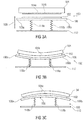
- Fig. 3(a) shows the capping device 100 in a non-capping or rest position distant from the print head 104.
- the capping device comprises a cap 102 mounted to a cap mount 106.
- the cap mount 106 is formed of a resilient material, like a thin metal plate or a thin plastic plate.
- the cap mount 106 is resilient such that after a deformation, e.g. due to the engagement with a curved print head surface 104a, it returns to its original unbend position.
- Fig. 3(b) shows the capping device 100 of Fig, 3(a) capping the print head 104 having a bowed surface 104a which is bowed towards the capping device in a similar way as shown in Fig. 2(b) .
- the central part of the cap 102 contacts the central part of the surface 104a of the print head 104 first.
- the flexible cap mount 106 is bend such that the outer end of the two portions 106a and 106b are bend upward with respect to the center of the cap mount.
- the flexibility allows for accommodating the bowed surface.
- the sheet or mount 106 to which the cap 102 is mounted is bent upwardly at the outer ends or edges, thereby providing for compliance of the cap 100 and allowing a reliable sealing operation.
- Fig. 3(c) shows the use of the capping device 100 of Fig. 3(a) for capping a print head 104 having a surface 104a being bowed away from the capping device.
- the cap 102 first engages the outer ends or periphery of the print head 104 thereby deflecting the flexible cap mount 106 downward at its outer ends, thereby allowing the central part of the cap 102 to engage the central part of the print head surface 104a and to pro- vide for the compliance of the cap 100 so that a reliable sealing operation is achieved.
- Fig. 4 shows further embodiments of a capping device 100.
- the cap mount portions 106a and 106b are linked or joined with each other such that they can be moved with respect to each other.
- a living hinge or a mechanical hinge is arranged between the two portions 106a and 106b.
- a capping device 100 that includes the cap 102 and the cap mount 106 mounted via two resilient members 1 18a and 1 18b to the support plate 1 12.
- the cap mount 106 is a continuous element having provided at a center thereof a notch 120 reducing the thickness of the cap mount 106 thereby forming a living hinge" 122.
- the notch 120 the rigidity of the cap mount 106 is reduced in the central part thereof so that the first cap mount portion 106a and the second cap mount portion 106b provided on the two sides of the notch 120 and coupled by the living hinge 122 can be moved with respect to each other upwards and downwards as indicated by the arrows 124, and as per the invention.
- the capping device 100 makes the elastomeric cap seal 102 that is attached to the semi-rigid cap mount 106 to conform to a curved surface 104a of a print head 104 in a way as was described with regard to Figs. 2 and 3 .
- the mechanical hinge may be formed of a plastic snap together hinge that allows motion about one axis, a plastic snap together hinge that allows motion about three axes like a ball hitch, a precision metal hinge that is fastened to or has overmolded platforms like 106a and 106b, or an elastomeric hinge that is fastened to or has overmolded platforms like 106a and 106b
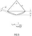
- Fig. 5 is a diagram in which R indicates the radius of curvature of a printer or print head, for example the surface 104a shown in Figs. 2 and 3 . Assuming a straight rigid cap mount, the cap seal has to deform by the distance h1 in order to seal on the curved surface.
- h1, h2 and the angle ⁇ is shown in Fig. 5 .
- h1 and h2 There is a linear relationship between h1 and h2 for a particular angle indicated in the equation given in Fig. 5 . For example, if ⁇ equals 90° ( ⁇ /2) then h1 will be 3.85 times h2. For ⁇ equal to 45° ( ⁇ /4) h1 will be 3.96 times h2. As the angle ⁇ becomes smaller, the ratio between h2 and h1 becomes 4 to 1.
- Fig. 6 shows another embodiment of a capping device 100.
- the capping device is similar to the one shown in Fig. 4(b) except that the cap mount 106 comprises three portions 106a to 106c, each connected by a mechanical hinge 126a-126b and each supported by a resilient member 118a to 118c on the support 112. More specifically, in a similar way as shown in Fig. 4(b) , the cap mount portions 106a and 106b are joined together by a mechanical hinge 126a. The cap mount portions 106b and 106c are joined together by a further mechanical hinge 126b. It is noted that other examples may use more than three cap mount portions hinged together.
- the cap mount 106 may be formed of/with more than two cap mount portions.
- the capping device shown in Fig. 4(a) may include a further notch thereby forming more than one living hinge and more than two portions for mounting the cap 102.
- Fig. 7 shows another embodiment of a capping device or cap assembly 200 in an exploded view.
- the cap assembly 200 may be used for page width printers using print heads extending over the entire page width that can be printed by such a printer.
- EPDM ethylene propylene diene monomer
- PPO polyphenylene oxide
- the cap 202 comprises a seal lip 230 for creating a vapor tight seal around the nozzles provided on a surface of a print head with which the cap's lip 230 engages.
- a labyrinth vent screw 232 is placed into an opening 233 in the cap 202.
- the cap 202 further comprises protrusions 234a-234f extending from a lower surface (the surface opposite to the one on which the seal 230 is formed) of the cap 202.
- the protrusions 234a and 234f are arranged at opposite ends of the cap 202 with one further protrusion 234b and 234e, respectively, adjacent thereto.
- the cap mount 206 is formed of a frame structure 240 having two parallel frame elements 240a and 240b which are connected with each other by plate elements 242a-242d of which plate elements 242a and 242b are arranged at opposite ends of the frame structure 240 of the cap mount 206.
- the plates 242c and 242d have a smaller dimension than the outer plates and are provided on both sides of the hinge 222.
- the distance between the plates 242a and 242c, the distance between the plates 242b and 242d and the distance between the plates 242c and 242d as well as the distance of the frames 240a and 240b is such that the recesses 236a-236c of the cap 202 may be received and accommodated in the space defined between the plates and the frame elements.
- the plates 242a to 242d comprise respective openings 244a-244f for receiving the protrusions 234a-234f formed at the lower side or surface of the cap 202.
- the springs 216a,b and 218a,b are received between the two frames 240a and 240b in such a way that the upper ends are supported by the lower surfaces of the plates 242a to 242d.
- the cap mount 206 further comprises clip elements 245 that engage with respective protrusions 247 on the support 212 when mounting the respective elements of the cap assembly 200 together.
- the cap mount support plate 212 may be formed from a plastic material, for example from PPO with fiber glass.
- the support 212 receives the lower ends of the springs 216a,b and 218a,b.
- the support 212 further comprises two locating features 250a and 250b that interface with the print bar.
- the springs 216a,b and 218a,b are compressed and the cap mount 206 with the cap 202 mounted thereto is received in a recess 252 of the support 206.
- the clip elements 245 and the protrusions 247 act together such that stops are defined which limit a vertical movement of the cap mount 206.
- the cap assembly shown in Fig. 7 further comprises a stiffening plate 256 that may be mounted to the support 206 via screws 258.
- the plate 256 may be formed of a metal, for example steel.
- the plate 256 is provided for supporting to the element 212 that may be formed from plastic.
- the plate 256 receives the forces applied by the springs to the element 212 to avoid any damage of element 212.
- Fig. 8 shows a view of a cap assembly 200 of Fig. 7 in a mounted state, with the stiffening plate 256 omitted.
- Fig. 9 shows a cross-sectional view in the x-z plane of the mounted assembly of Fig. 8 .
- the vent screw 232 is provided in the opening 233 of the protrusion 234d which is received by the opening 244d on the right side of the notch 220.
- the other openings 244a-244c and 244e-244f shown in Fig. 7 receive the protrusions 234a-234c and 234e-234f of the cap 202.
- the protrusions 234a-234f have a thickened front part allowing the insertion into the hole and securing same therein.
- the cap mount comprises cup-shaped portions 280a-280d formed below plates 244b, 244c, 244d and 244e.
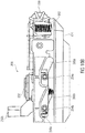
- Fig. 10 shows schematic representations illustrating the movement of a cap assembly 200, e.g. the one shown in Figs. 7 to 9 , from a position of disengagement with the print head to a position capping the print head.
- the print head 104 (not shown in Fig. 10 ) is mounted at a fixed position and the cap assembly 200 is mounted moveably.
- Fig. 10(a) is an isometric view showing a part of a printer holding the cap assembly 200.
- Fig. 10(a) shows a roller 300 for transporting a recording medium into a print zone of the printer.
- the roller 300 is resiliently supported (see spring 302) by a frame 304.
- Fig. 11 shows an example of a printer in which a capping device in accordance with embodiments may be used.
- Fig. 11 is a schematic representation of a printer 500 having a print head 502 that can be mounted along a rod 504 back and forth to allow printing of characters and the like onto a sheet of paper that is provided on a platen 506 from a paper magazine 508. Printing occurs as the print head reciprocates along the rod 504 and as the sheet is forwarded.
- the printer 500 comprises a service/maintenance station 510 at the right side of the printer housing 512.
- the service/maintenance station 510 includes a capping device 514 as described above. As indicated by the arrow, the capping device 514 may be moved from a retracted position into an upward position for capping the print head's nozzles 502a.
Landscapes
- Ink Jet (AREA)
Description
- The present invention relates to a print head capping device as per the preamble of
claim 1. Such a print head capping device is known from the documentUS2008/0231655A1 . - A print head, e.g. an inkjet print head, includes a reservoir holding the printing material, e.g. liquid ink. The print head further includes a plurality of nozzles being in fluid communication with the reservoir. The nozzles are provided at a surface of the print head and allow expelling the print material held in the reservoir onto a recording medium, e.g. a sheet of paper. During a print operation the print head and the recording medium move relative to each other for generating a desired print out, e.g. an image or text, on the recording medium by expelling the print material from the reservoir via the nozzles onto the recording medium.
- When the printer including such a print head is inoperative the nozzles are not used. Leaving the nozzles in such an operating state unprotected may cause an interaction between the print material in the reservoir and the environment which may have a detrimental effect on the printing material, e.g. an ink, held in the reservoir. This interaction may cause a vapor transmission from the print material via the nozzles. In addition, the nozzles may be effected, e.g. by clogging due to dried print material particles.
- To avoid such detrimental effects a printer is provided with a capping system that includes an elastomeric or flexible cap held by a support element. The cap can be brought into engagement with the print head to form a seal around the nozzles. Providing a cap on the print head in an idle state of the print head extends the life time and the reliability of the print head. To reliably seal the nozzles the cap is in a continuous engagement with a surface of the print head on which the nozzles are arranged so that leaks are avoided.
- However, print heads and/or the cap support element may not be manufactured perfectly. The print head surface and/or the cap support element may not be perfectly straight, e.g. the print head surface and /or the cap support element may have a curvature. The print head may have two ends along a dimension that are recessed when compared to a center part. In another case the center part of the print head may be recessed when compared to the ends along a dimension of the print head. This results in a bow or a curvature in the print head surface that needs to be compensated for by the elastomeric cap yielding a specific degree of compliance. However, such compliance of the cap material is finite. In case the bow or curvature becomes excessive, despite the compliance of the cap material a complete seal around the nozzles may no longer be achieved. In case the center part of the print head is recessed a leak in the seal at this part may occur as the cap rests tightly on the opposed ends of the print head and is compressed there, however, the compliance of the material is not sufficient to also allow for a tight seal at the central part of the print surface. This reduces the effects achievable by providing the cap around nozzles of a print head.
- This problem may be encountered in any kind of print head, however, the larger the dimension of a print head and the larger the dimension of the cap for sealing the print head become, the more severe this problem becomes as manufacturing such elements in accordance with the desired tolerances becomes more difficult. For example, in a page width printer a print head or print bar is used that extends over the print area, e.g. over the width of a page to be printed. Such a print bar and the associated capping system may be made from long parts made of plastic and/or metal that are difficult to manufacture perfectly straight so that these parts may have a curvature which may not be compensated for by the elastomeric cap material so that the above mentioned leak in the seal may occur.
-
- Fig. 1
- illustrates an embodiment of a print head capping device;
- Fig. 2
- shows the capping device of
Fig. 1 compensating a curvature or bending in the surface of the print head,Fig. 2(a) showing a print head having a surface with a bending or bow in a direction away from the capping device, andFig. 2(b) showing a print head having a surface with a bending or bow in a direction towards the capping device; - Fig. 3
- shows another embodiment of a capping device and its functionality for capping a print head according to the invention,
Fig. 3(a) showing the capping device in a non-capping or rest position distant from the print head,Fig. 3(b) showing the capping device capping the print head having a surface bowed towards the capping device, andFig. 3(c) showing the capping device capping the print head having a surface bowed away from the capping device; - Fig. 4
- shows further embodiments of a capping device,
Fig. 4(a) showing a capping device having a living hinge between the cap mount portions, andFig. 4(b) showing a capping device having a mechanical hinge between the cap mount portions; - Fig. 5
- shows a diagram for illustrating the advantages of the capping de- vices described in this specification when compared to devices not having an articulated cap mount;
- Fig. 6
- shows another embodiment of a capping device having a cap mount including three portions;
- Fig. 7
- shows an exploded view of another embodiment of a capping assembly;
- Fig. 8
- shows of the cap assembly of
Fig. 7 in a mounted state; - Fig. 9
- shows a cross- sectional view in the x-z plane of the mounted cap assembly of
Fig. 8 ; - Fig. 10
- shows schematic representations illustrating the movement of a cap assembly shown in
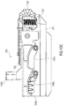
Figs. 7 to 9 between an at-rest position and a capped position, whereinFig. 10(a) is an isometric view showing a part of a printer holding the cap assembly,Fig. 10(b) is a side view of the structure ofFig. 10(a) with the cap assembly at an elevated position, andFig. 10(c) is a side view of the structure ofFig. 10(a) with the cap assembly at a lowered position; - Fig. 11
- shows an example of a printer in which a capping device in accordance with embodiments may be used; and
- Fig. 12
- shows an example of another printer in which a capping device in accordance with embodiments may be used.
- Embodiments relate to a capping device for a print head which includes a cap for engaging the print head to seal e.g. the nozzles of the print head and a cap mount supporting the cap. The capping device tolerates and compensates for a curvature of a print head surface and/or the cap mount by providing the cap mount to which the cap is attached with two portions that can be moved with respect to each other. This allows for the cap to be able to conform to a print head even in case the print head and/or the cap mount are not perfectly straight, e.g. show an excessive curvature. Thus, the capping device adds compliance to the cap in a way to accommodate for the imperfections of the manufacturing of the print head and/or the cap mount.
- E.g. a long print bar assembly used in a page width printer may be difficult to manufacture in a completely straight manner. Also, parts of the cap device or assembly are long and may also be difficult to manufacture completely straight. This results in the above described problem as the cap may contact the print bar with a reliable seal at the center of the print head but not at its ends or vice versa. Arranging the cap on a cap support or mount having two portions that can be moved with respect to each other provides for an extra degree of freedom that allows the cap to conform to the print bar even in case of a curvature. This also applies in case cap assembly parts, like the cap mount have a curvature.
-
Fig. 1 illustrates an embodiment of a printhead capping device 100 that comprises aflexible cap 102 that is configured to engage asurface 104a of aprint head 104. On thesurface 104a the print head'snozzles 104b are arranged. Thecap 102 is mounted to acap mount 106 that includes according to the invention afirst portion 106a and asecond portion 106b. The first and secondcap mount portions arrow 108. In accordance with the invention, the first and secondcap mount portions Fig. 1 ) extending through thecap 102 and thecap mount 106. The first and secondcap mount portions respective surfaces cap 102 is mounted and which extends in the x-y plane. Thecapping device 100 is moveable between a first position (a non-capping position) as shown inFig. 1 and a second position (the capping position). In the first position thecap 102 is not in engagement with theprint head 104 and thenozzles 104b of theprint head 104 are not sealed by thecap 102. In the second position thecap 102 engages thesurface 104a of theprint head 104 and provides the desired seal. To be moved between the capping position and the non-capping position the printhead capping device 100 is moveable in the vertical direction, for example the z-direction. The first andsecond portions cap mount 106 are moveable with respect to each other also at least along the z-direction. -
Fig. 2 shows examples of thecapping device 100 for compensating a curvature or bending in thesurface 104a of theprint head 104.Fig. 2(a) shows aprint head 104 having asurface 104a with a bending or bow in a direction away from thecapping device 100. To be more specific, a distance between a central portion of thesurface 104a and the capping device is larger than a distance between edge portions of thesurface 104a and the capping device. InFig. 2(a) the bending of thesurface 104a is shown in an exaggerated scale to explain the functionality of thecapping device 100.Fig. 2(a) shows the situation in which thecapping device 100 was moved along the z-direction from the non-capping position (seeFig. 1 ) to the capping position in which thecap 102 engages thesurface 104a of theprint head 104. In thecapping device 100 in accordance with the example shown inFig. 2(a) the first and secondcap mount portions gimbal plate 112 and are separated by agap 114. Thecap mount portions cap mount portions gap 112, and second ends are arranged proximate to thegap 114 and opposed to each other. The firstcap mount portion 106a is mounted via a firstresilient member 116a and a secondresilient member 118a to thesupport plate 112. The firstresilient member 118a is mounted near the first end of the firstcap mount portion 106a, and the secondresilient member 118a is mounted near the second end of the firstcap mount portion 106a. The secondcap mount portion 106b is supported in a similar manner by a firstresilient member 116b near the first end and by a secondresilient member 118b near the second end. Theresilient members 116a,b and 118a,b may be springs, for example coil springs. - In the capping position shown in
Fig. 2(a) thecap 102 engages thelower surface 104a of theprint head 104 for sealing e.g. thenozzles 104b (seeFig. 1 ) of theprint head 104. Upon engaging theprint head surface 104a first ends (the outer ends along the x-direction) of thecap 102 contact an area of theprint head 104 close to the outer ends (along the x-direction) of theprint head 104. Theprint head 104 is at a fixed position so that due to the movement of thecapping device 100 towards and into contact with theprint head 104 the resiliently supportedcap mount portions Fig. 2(a) this movement is shown in an exaggerated manner. Thecap mount portions cap 102 to conform better to theprint head surface 104a. As the movement continues, also the center part of thecap 102 engages the center part of theprint head 104 and the outer ends of thecap mount portions resilient members resilient members cap mount portions capping device 100 allows thecap 102 to conform the to thebend surface 104a better without reaching a compliance limit so that thecap 102 reliably seals all desired portions of theprint head 104. -
Fig. 2(b) illustrates the functionality of thecapping device 100 when capping aprint head 104 having asurface 104a that is bend or bowed into the direction of thecapping device 100. To be more specific, a distance between a central portion of thesurface 104a and the capping device is smaller than a distance between edge portions of thesurface 104a and the capping device. Again, the bending of theprint head surface 104a is shown in an exaggerated manner. In the example shown inFig. 2(b) theresilient members 116a,b and 118a,b are leaf springs which may also be used instead of the coil springs shown in the example inFig. 2(a) . Upon engaging theprint head 104 by moving thecapping device 100 from the rest position (seeFig. 1 ) against thesurface 104a of theprint head 104 the central part of thecap 102 engages a central part of theprint head 104 first, so that the centralresilient members 1 18a and 1 18b will be compressed first. Upon further moving thecapping device 100 towards theprint head surface 104a the outer edges of thecap 100 engage the outer edges of theprint head 104 so that also the outerresilient members Fig. 2(a) , the centralresilient members 1 18a and 1 18b are compressed more than the outerresilient members 1 16a and 1 16b. The effect is the same as inFig. 2(a) , in that thecap 100 complies with thebend surface 104a of theprint head 104, thereby ensuring a reliable sealing operation of thecap 100. - In
Fig. 2 each of thecap mount portions 106a and 108b is resiliently supported by tworesilient members 1 18a,b and 1 18a,b. Other examples may use a different number of resilient members, for example one resilient member for each cap mount portion or more than two resilient members for each cap mount portion, e.g. dependent on the dimension of the capping device. Also, other examples may use more than two cap mount portions, for example an additional, third cap mount portion or even more cap mount portions that are all moveable with respect to each other, thereby accommodating for print heads having a very long x-dimension. -
Fig. 3 shows another embodiment of acapping device 100 according to the invention and its functionality for capping a print head.Fig. 3(a) shows thecapping device 100 in a non-capping or rest position distant from theprint head 104. The capping device comprises acap 102 mounted to acap mount 106. Thecap mount 106 is formed of a resilient material, like a thin metal plate or a thin plastic plate. Thecap mount 106 is resilient such that after a deformation, e.g. due to the engagement with a curvedprint head surface 104a, it returns to its original unbend position. The cap mount 110 is supported by tworesilient members support plate 112 and afirst portion 106a and asecond portion 106b of thecap mount 106. Thecap 102 is attached to thecap mount 106 such that it is mounted both to the first portion 108a and to the second portion 108b. InFig. 3(a) theprint head 104 is schematically shown. For an engagement with theprint head 104 thecapping device 100 is moved in the direction indicated byarrow 108 towards theprint head 104. -
Fig. 3(b) shows thecapping device 100 ofFig, 3(a) capping theprint head 104 having a bowedsurface 104a which is bowed towards the capping device in a similar way as shown inFig. 2(b) . Upon bringing the capping device into engagement with theprint head 104 the central part of thecap 102 contacts the central part of thesurface 104a of theprint head 104 first. When the cap is in engagement with theentire surface 104a of theprint head 104 theflexible cap mount 106 is bend such that the outer end of the twoportions cap 102 is mounted is bent upwardly at the outer ends or edges, thereby providing for compliance of thecap 100 and allowing a reliable sealing operation. -
Fig. 3(c) shows the use of thecapping device 100 ofFig. 3(a) for capping aprint head 104 having asurface 104a being bowed away from the capping device. Like in the example depicted inFig. 2(a) , thecap 102 first engages the outer ends or periphery of theprint head 104 thereby deflecting theflexible cap mount 106 downward at its outer ends, thereby allowing the central part of thecap 102 to engage the central part of theprint head surface 104a and to pro- vide for the compliance of thecap 100 so that a reliable sealing operation is achieved. -
Fig. 4 shows further embodiments of acapping device 100. Other than inFig. 2 , thecap mount portions portions - In
Fig. 4(a) acapping device 100 is shown that includes thecap 102 and thecap mount 106 mounted via tworesilient members 1 18a and 1 18b to thesupport plate 1 12. Thecap mount 106 is a continuous element having provided at a center thereof anotch 120 reducing the thickness of thecap mount 106 thereby forming a living hinge" 122. By means of thenotch 120 the rigidity of thecap mount 106 is reduced in the central part thereof so that the firstcap mount portion 106a and the secondcap mount portion 106b provided on the two sides of thenotch 120 and coupled by the livinghinge 122 can be moved with respect to each other upwards and downwards as indicated by thearrows 124, and as per the invention. - The
capping device 100 makes theelastomeric cap seal 102 that is attached to thesemi-rigid cap mount 106 to conform to acurved surface 104a of aprint head 104 in a way as was described with regard toFigs. 2 and3 . -
Fig. 4(b) shows another embodiment of acapping device 100. Instead of providing a living hinge as shown inFig. 4(a) the capping device ofFig. (4(b) includes amechanical hinge 126 that connects the twoportions Fig. 4(b) the twocap mount portions support plate 112 by means ofresilient members portions support 112 to allow for the functionality described above. - The mechanical hinge may be formed of a plastic snap together hinge that allows motion about one axis, a plastic snap together hinge that allows motion about three axes like a ball hitch, a precision metal hinge that is fastened to or has overmolded platforms like 106a and 106b, or an elastomeric hinge that is fastened to or has overmolded platforms like 106a and 106b
- The examples described in the specification operate in the same way in case the surface of the print head, the headland, is flat but the cap mount is curved. If the cap mount is hinged in a way as shown in
Fig. 4 , e.g. in its middle, the distance that the cap or cap seal has to deflect in order to conform to the surface of the print head is reduced. Thus, an advantage of an articulated cap mount is that it is able to conform to irregular or curved surfaces that a straight rigid cap mount would not be able to seal on. Indeed, if due to manufacturing difficulties the cap mount itself is not straight, which may be a problem with long plastic or metal parts, the articulated cap mount is also able to deflect at its joints and the cap seal is still able to conform to the headland surface and create a vapor tight seal around the nozzles of the print head. With reference toFig. 5 the advantages of the capping devices described in this specification when compared to devices not having an articulated cap mount are described.Fig. 5 is a diagram in which R indicates the radius of curvature of a printer or print head, for example thesurface 104a shown inFigs. 2 and3 . Assuming a straight rigid cap mount, the cap seal has to deform by the distance h1 in order to seal on the curved surface. However, if the cap mount has a joint or a hinge in the middle or is mounted to two parts moveable with respect to each other the cap seal has to deform by the smaller distance h2. The relationship between h1, h2 and the angle θ is shown inFig. 5 . There is a linear relationship between h1 and h2 for a particular angle indicated in the equation given inFig. 5 . For example, if θ equals 90° (π/2) then h1 will be 3.85 times h2. For θ equal to 45° (π/4) h1 will be 3.96 times h2. As the angle θ becomes smaller, the ratio between h2 and h1 becomes 4 to 1. -
Fig. 6 shows another embodiment of acapping device 100. The capping device is similar to the one shown inFig. 4(b) except that thecap mount 106 comprises threeportions 106a to 106c, each connected by amechanical hinge 126a-126b and each supported by aresilient member 118a to 118c on thesupport 112. More specifically, in a similar way as shown inFig. 4(b) , thecap mount portions mechanical hinge 126a. Thecap mount portions mechanical hinge 126b. It is noted that other examples may use more than three cap mount portions hinged together. It is further noted that also in the capping devices described above inFigs 1 to 4 thecap mount 106 may be formed of/with more than two cap mount portions. E.g. the capping device shown inFig. 4(a) may include a further notch thereby forming more than one living hinge and more than two portions for mounting thecap 102. -
Fig. 7 shows another embodiment of a capping device orcap assembly 200 in an exploded view. Thecap assembly 200 may be used for page width printers using print heads extending over the entire page width that can be printed by such a printer. Thecap assembly 200 comprises anelastic cap 202 that may be formed from an elastomer material, like EPDM (EPDM = ethylene propylene diene monomer). Thecap 202 is mounted to acap mount 206 that may be formed from a plastic material, like PPO (PPO = polyphenylene oxide) or a flexible polypropylene material. In case the printer is an inkjet printer the materials for thecap assembly 200 that are likely to come into contact with the ink are formed from a material that is compatible with the ink used in the print head to be capped. Thecap assembly 200 further comprises asupport 212 by which thecap mount 206 with acap 202 mounted thereto is resiliently supported. Thecap mount 206 comprises anotch 220 defining theliving hinge 222 so that the cap support or mount 206 comprises the first cap mount orsupport portion 206a formed on one side of thehinge 222 and the second cap mount orsupport portion 206b formed on the other side of thehinge 222. The firstcap mount portion 206a is mounted to thesupport 212 via a first,outer spring 216a and a second,inner spring 218a. Likewise, the secondcap mount portion 206b is mounted to thesupport 206 via a first,outer spring 216b and a second,inner spring 218b. - The
cap 202 comprises aseal lip 230 for creating a vapor tight seal around the nozzles provided on a surface of a print head with which the cap'slip 230 engages. To allow for a venting of the sealed space between thecap 202 and the print head alabyrinth vent screw 232 is placed into anopening 233 in thecap 202. Thecap 202 further comprisesprotrusions 234a-234f extending from a lower surface (the surface opposite to the one on which theseal 230 is formed) of thecap 202. Theprotrusions cap 202 with onefurther protrusion cap 200 comprises threerecesses 236a-236c for receivingabsorber strips 238a to 238c. The absorber strips receive ink that may be leaking from the print head. Thefirst recess 236a is arranged between theprotrusions second recess 236b is arranged between theprotrusions third recess 236c is arranged between theprotrusions protrusion 234d includes theopening 233 for receiving thevent screw 232. - The
cap mount 206 is formed of aframe structure 240 having twoparallel frame elements plate elements 242a-242d of whichplate elements frame structure 240 of thecap mount 206. Theplates hinge 222. The distance between theplates plates plates frames recesses 236a-236c of thecap 202 may be received and accommodated in the space defined between the plates and the frame elements. Further, theplates 242a to 242d compriserespective openings 244a-244f for receiving theprotrusions 234a-234f formed at the lower side or surface of thecap 202. - The
springs 216a,b and 218a,b are received between the twoframes plates 242a to 242d. - The
cap mount 206 further comprisesclip elements 245 that engage withrespective protrusions 247 on thesupport 212 when mounting the respective elements of thecap assembly 200 together. - The cap
mount support plate 212 may be formed from a plastic material, for example from PPO with fiber glass. Thesupport 212 receives the lower ends of thesprings 216a,b and 218a,b. Thesupport 212 further comprises two locatingfeatures elements springs 216a,b and 218a,b are compressed and thecap mount 206 with thecap 202 mounted thereto is received in arecess 252 of thesupport 206. Theclip elements 245 and theprotrusions 247 act together such that stops are defined which limit a vertical movement of thecap mount 206. Thecap mount 206 is arranged at a position inside therecess 252 in such a way that a predefined amount of vertical movement between the stop and a bottom of therecess 252 is allowed. This provides for the freedom of movement of therespective portions cap mount 206 for accommodating curved surfaces of the print head. Also, thecap mount 202 may be accommodated inside therecess 252 in such a way that a tilting of the cap mount around the x-axis and the y-axis is possible for allowing compensating any inclined arrangement of the print head around the just mentioned axis due to manufacturing or assembly tolerances. Thesupport 212 further comprises fourpins 254a to 254d for guiding of thecap assembly 200 in a way as shall be discussed below. - The cap assembly shown in
Fig. 7 further comprises astiffening plate 256 that may be mounted to thesupport 206 viascrews 258. Theplate 256 may be formed of a metal, for example steel. Theplate 256 is provided for supporting to theelement 212 that may be formed from plastic. Theplate 256 receives the forces applied by the springs to theelement 212 to avoid any damage ofelement 212. -
Fig. 8 shows a view of acap assembly 200 ofFig. 7 in a mounted state, with thestiffening plate 256 omitted. -
Fig. 9 shows a cross-sectional view in the x-z plane of the mounted assembly ofFig. 8 . Thevent screw 232 is provided in theopening 233 of theprotrusion 234d which is received by theopening 244d on the right side of thenotch 220. Theother openings 244a-244c and 244e-244f shown inFig. 7 receive theprotrusions 234a-234c and 234e-234f of thecap 202. Theprotrusions 234a-234f have a thickened front part allowing the insertion into the hole and securing same therein. Further, the cap mount comprises cup-shapedportions 280a-280d formed belowplates springs 216a,b and 218a,b that are guided by cup-shaped portions. The upper parts of thesprings 216a,b and 218a,b are guided by the cup-like portions of themount 206, and the lower parts of thesprings 216a,b and 218a,b are guided byX-shaped protrusions 282a-282d formed on a bottom of thesupport plate 212. Thesupport plate 212 is mounted with a distance d from thecap mount 206 thereby allowing for the bending of therespective portions cap mount 200 for accommodating for bends or curvatures of the print head as described above. -
Fig. 10 shows schematic representations illustrating the movement of acap assembly 200, e.g. the one shown inFigs. 7 to 9 , from a position of disengagement with the print head to a position capping the print head. In the printer it is assumed that the print head 104 (not shown inFig. 10 ) is mounted at a fixed position and thecap assembly 200 is mounted moveably.
Fig. 10(a) is an isometric view showing a part of a printer holding thecap assembly 200.Fig. 10(a) shows aroller 300 for transporting a recording medium into a print zone of the printer. Theroller 300 is resiliently supported (see spring 302) by aframe 304. Theframe 304 comprises elongatedguide holes 306a-c extending from a lower horizontal part via an inclined part to an upper horizontal part. Thecap assembly 200 is movably mounted with respect to theframe 304. Thepins 254a-d of thecap assembly 200 described with regard toFigs. 7 to 9 are received in theelongated guide holes 306a-c. Thecap assembly 200 is biased by thesprings 308a-b towards the position shown inFig. 10(a). Fig. 10(a) shows thecap assembly 200 at a capped position where the pins 254 are in the upper part of the holes 306 so that thecap assembly 200 is at en elevated position with regard toroller 300 so that itselastic cap 202 is in engagement with the lower side or surface of the print head for sealing the print head nozzles.Fig. 10(b) is a side view of the structure ofFig. 10(a) from which the elevated position of thecap 202 can be seen.Fig. 10(c) is a side view of the structure ofFig. 10(a) with the cap assembly at its at-rest position where the pins 254 are in the lower part of the holes 306 so that thecap assembly 200 is at a lowered position with regard to theroller 300 so that itselastic cap 202 is not in engagement with the lower side or surface of the print head so that printing is allowed. -
Fig. 11 shows an example of a printer in which a capping device in accordance with embodiments may be used.Fig. 11 is a schematic representation of aprinter 500 having aprint head 502 that can be mounted along arod 504 back and forth to allow printing of characters and the like onto a sheet of paper that is provided on aplaten 506 from apaper magazine 508. Printing occurs as the print head reciprocates along therod 504 and as the sheet is forwarded. Further, theprinter 500 comprises a service/maintenance station 510 at the right side of theprinter housing 512. The service/maintenance station 510 includes acapping device 514 as described above. As indicated by the arrow, thecapping device 514 may be moved from a retracted position into an upward position for capping the print head'snozzles 502a. -
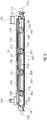
Fig. 12 shows an example of another printer in which a capping device in accordance with embodiments may be used.Fig. 12(a) is a schematic representation of aprinter 600 which is a so-called page width printer. The printer comprises aprint head 602 extending substantially over a predefined width covering e.g. the width of a sheet of paper provided to aplaten 606 from apaper magazine 608, thereby allowing printing onto the paper without a movement of the print head. For capping the print head 602 acapping device 614 as it was described above may be provided. The cappingassembly 614 may be engaged with theprint head 602 in a way as described inFig. 10 .Fig. 12(b) shows theprint head 602 with thecapping device 614 in position. - The capping device described above may be used with any print head, e.g. the print head of an inkjet printer. The capping device may be used in any kind of printing device, e.g. desktop printers, page width printers, plotters and the like.
Claims (13)
- A print head capping device (100) for compensating a curvature or bending in a surface (104a) of a print head (104, 502), comprising:a flexible cap (102) configured to engage with the print head (104, 502); and a cap mount (106) including a first portion (106a) and a second portion (106b), the cap (102) being mounted to the first portion (106a) and to the second portion (106b) and the first portion (106a) of the cap mount (106) and the second portion (106b) of the cap mount (106) being moveable with respect to each other, wherein when the cap (102) is in engagement with the entire surface (104a) of the print head (104, 502) the flexible cap mount (106) is bend such that the outer end of the two portions (106a, 106b) are bend upwards with respect to a center of the cap mount (106), wherein the first portion (106a) of the cap mount (106) and the second portion (106b) of the cap mount (106) are moveable along an axis extending through the cap (102) and the cap mount (106),wherein each of the first and second portions (106a, 106b) of the cap mount (106) include a surface, characterized in that the cap (102) is mounted to the surface of the first and second portions (106a, 106b) of the cap mount (106), andwherein the axis is perpendicular to the surface.
- The print head capping device (100) of claim 1,
wherein the cap mount (106) comprises a third portion (106c),
wherein the cap (102) is mounted to the first, second and third portions (106a, 106b, 106c) of the cap mount (106), and
wherein the first, second and third portions (106a, 106b, 106c) of the cap mount (106) are moveable with respect to each other. - The print head capping device (100) of claim 1, wherein the cap mount (106) includes a hinge (122) connecting the first and second portions (106a, 106b) of the cap mount (106).
- The print head capping device (100) of claim 3, wherein the hinge (122) comprises a living hinge (222) or a mechanical hinge (126).
- The print head capping device (100) of claim 1, wherein the first and second portions (106a, 106b) of the cap mount (106) are separately and resiliently supported.
- The print head capping device (100) of claim 1, further comprising a support plate (112, 212) supporting the cap mount (106).
- The print head capping device (100) of claim 6, further comprising: at least one resilient element arranged between the first portion (106a) of the cap mount (106) and the support plate (112), and
at least one second resilient element arranged between the second portion (106b) of the cap mount (106) and the support plate (112). - The print head capping device (100) of claim 7, wherein the first and second resilient elements comprise a spring (216a, 216b, 218a, 218b).
- The print head capping device (100) of claim 6, wherein the plate comprises a stop, wherein a clip element (245) and a protrusion (247) acting together define a stop, the stop being configured to limit a movement of the first and second portions (106a, 106b) of the cap mount (106) to a predefined distance in a direction away from the support plate (112, 212).
- The print head capping device (100) of claim 1 comprising:
the cap mount (106) including a living hinge (222) between a first portion (106a) of the cap mount (106) and a second portion (106b) of the cap mount (106):a support plate (112, 212);a first spring (216a, 216b) arranged between the first portion (106a) of the cap mount (106) and the support plate (112, 212); anda second spring (218a, 218b) arranged between the second portion (106b) of the cap mount (106) and the support plate (112, 212),wherein the first and second springs (216a, 216b, 218a, 218b) are arranged such that the first and second portions (106a, 106b) are moveable with respect to each other between a first position distant from the support plate (112, 212) and a second position close to the support plate (112, 212),wherein when the cap (102) is in engagement with the entire surface (104a) of the print head (104, 502) the flexible cap mount (106) is bend such that the outer end of the two portions (106a, 106b) are bend upwards with respect to a center of the cap mount (106). - A printer (500), comprising:
a print head (104, 502); and a print head capping device (100) for compensating a curvature or bending in a surface (104a) of a print head (104) of claim 1. - The printer (500) of claim 11, wherein the print head (104, 502) comprises a page width inkjet print head.
- The printer (500) of claim 11, comprising:
a mechanism configured to move the print head capping device (100) between a first position capping the print head (104, 502) and a second position not capping the print head (104, 502).
Applications Claiming Priority (1)
| Application Number | Priority Date | Filing Date | Title |
|---|---|---|---|
| PCT/US2010/054201 WO2012057741A1 (en) | 2010-10-27 | 2010-10-27 | Print head capping device and printer |
Publications (3)
| Publication Number | Publication Date |
|---|---|
| EP2632728A1 EP2632728A1 (en) | 2013-09-04 |
| EP2632728A4 EP2632728A4 (en) | 2018-03-07 |
| EP2632728B1 true EP2632728B1 (en) | 2020-06-24 |
Family
ID=45994214
Family Applications (1)
| Application Number | Title | Priority Date | Filing Date |
|---|---|---|---|
| EP10859059.7A Active EP2632728B1 (en) | 2010-10-27 | 2010-10-27 | Print head capping device and printer |
Country Status (4)
| Country | Link |
|---|---|
| US (1) | US8926059B2 (en) |
| EP (1) | EP2632728B1 (en) |
| CN (1) | CN103237660B (en) |
| WO (1) | WO2012057741A1 (en) |
Families Citing this family (26)
| Publication number | Priority date | Publication date | Assignee | Title |
|---|---|---|---|---|
| US9211716B2 (en) * | 2011-09-13 | 2015-12-15 | Videojet Technologies Inc. | Capping device |
| DE112012006893T5 (en) | 2012-09-12 | 2015-05-28 | Hewlett-Packard Development Company, L.P. | Cover assembly for a printhead device |
| JP2016141119A (en) * | 2015-02-04 | 2016-08-08 | セイコーエプソン株式会社 | Liquid ejecting head and liquid ejecting device |
| US10703620B1 (en) | 2015-04-06 | 2020-07-07 | Steven P. Keeling | Beverage dispensing system |
| JP6727061B2 (en) * | 2016-07-29 | 2020-07-22 | 理想科学工業株式会社 | Printer |
| JP7043326B2 (en) * | 2018-04-06 | 2022-03-29 | 株式会社ミマキエンジニアリング | Capping mechanism and inkjet printer |
| KR102598357B1 (en) | 2018-09-04 | 2023-11-07 | 프로토타입 앤드 프로덕션 시스템스, 인코포레이티드 | Adaptive printhead positioning device for print modules |
| JP7206791B2 (en) * | 2018-10-19 | 2023-01-18 | 京セラドキュメントソリューションズ株式会社 | Recording head cap unit and inkjet recording apparatus having the same |
| US10518537B1 (en) | 2018-11-29 | 2019-12-31 | Xerox Corporation | System and method for attenuating the drying of ink from a printhead |
| US10632757B1 (en) | 2018-12-10 | 2020-04-28 | Xerox Corporation | System and method for attenuating the drying of ink from a printhead during idle periods |
| US10518551B1 (en) | 2018-12-11 | 2019-12-31 | Xerox Corporation | System and method for attenuating the drying of ink from a printhead |
| US10710370B2 (en) | 2018-12-18 | 2020-07-14 | Xerox Corporation | System and method for attenuating the drying of ink from a printhead during periods of printhead inactivity |
| US10814631B2 (en) | 2019-02-11 | 2020-10-27 | Xerox Corporation | Inkjet printhead cap having rotatable panels |
| US10800174B2 (en) | 2019-02-11 | 2020-10-13 | Xerox Corporation | Evaporative ink-blocking film devices stabilizing ink in nozzles of inkjet printheads |
| US10857798B2 (en) | 2019-02-11 | 2020-12-08 | Xerox Corporation | Cap and evaporative devices stabilizing ink in nozzles of inkjet printheads |
| US10696052B1 (en) | 2019-02-11 | 2020-06-30 | Xerox Corporation | Submersion cap devices stabilizing ink in nozzles of inkjet printheads |
| US10894411B2 (en) | 2019-02-11 | 2021-01-19 | Xerox Corporation | Cap and application devices stabilizing ink in nozzles of inkjet printheads |
| US10710371B1 (en) | 2019-02-11 | 2020-07-14 | Xerox Corporation | Inkjet printhead cap having latching system |
| US10717284B1 (en) | 2019-03-28 | 2020-07-21 | Xerox Corporation | System and method for attenuating the drying of ink from a printhead during periods of printer inactivity |
| US10889117B2 (en) | 2019-03-28 | 2021-01-12 | Xerox Corporation | System and method for attenuating the drying of ink from a printhead during periods of printer inactivity |
| US10919299B1 (en) * | 2019-09-05 | 2021-02-16 | Xerox Corporation | System and method to counteract the drying of aqueous inks in a printhead |
| US11383525B2 (en) | 2020-06-10 | 2022-07-12 | Xerox Corporation | System and method for efficiently purging printheads |
| JP7494073B2 (en) | 2020-09-23 | 2024-06-03 | 株式会社Screenホールディングス | PRINTING DEVICE AND METHOD FOR MAINTENANCE OF INK EJECTION HEAD |
| CN113147193B (en) * | 2021-04-23 | 2023-02-14 | 浙江科技学院 | Locking mark scribbles and beats device |
| JP7344930B2 (en) * | 2021-06-17 | 2023-09-14 | ローランドディー.ジー.株式会社 | Cap and inkjet printer with it |
| CN117642293B (en) * | 2021-07-16 | 2026-01-02 | 惠普发展公司,有限责任合伙企业 | Printhead die cover |
Family Cites Families (16)
| Publication number | Priority date | Publication date | Assignee | Title |
|---|---|---|---|---|
| JP3222673B2 (en) * | 1993-12-30 | 2001-10-29 | キヤノン株式会社 | Cap mechanism, inkjet device and information processing system |
| US5936647A (en) * | 1996-10-31 | 1999-08-10 | Hewlett-Packard Company | Flexible frame onsert capping of inkjet printheads |
| JP2000343716A (en) * | 1999-06-08 | 2000-12-12 | Casio Comput Co Ltd | Inkjet printer head |
| US6273547B1 (en) * | 1999-10-27 | 2001-08-14 | Lexmark International, Inc. | Waste ink collection system for an ink jet printer |
| US6406124B1 (en) * | 2000-01-31 | 2002-06-18 | Hewlett-Packard Company | Ganged inkjet printhead capping system |
| DE10114541A1 (en) * | 2001-03-21 | 2002-10-02 | Francotyp Postalia Ag | Device for printing |
| US7229149B2 (en) | 2003-08-11 | 2007-06-12 | Hewlett-Packard Development Company, L.P. | Service station and method for servicing drum printer |
| JP2005193568A (en) * | 2004-01-08 | 2005-07-21 | Sony Corp | Nozzle cap, head cap unit, and liquid discharge head |
| US6984017B1 (en) * | 2004-12-06 | 2006-01-10 | Silverbrook Research Pty Ltd | Inkjet printer incorporating a reel-to-reel flexible capping member |
| KR100694115B1 (en) | 2005-05-25 | 2007-03-12 | 삼성전자주식회사 | Inkjet image forming apparatus having a cap member |
| JP4696820B2 (en) * | 2005-09-30 | 2011-06-08 | ブラザー工業株式会社 | Inkjet recording device |
| JP4932552B2 (en) * | 2007-03-19 | 2012-05-16 | 理想科学工業株式会社 | Image forming apparatus equipped with maintenance mechanism |
| JP4888360B2 (en) * | 2007-11-30 | 2012-02-29 | ブラザー工業株式会社 | Droplet discharge device |
| KR20100041531A (en) * | 2008-10-14 | 2010-04-22 | 삼성전자주식회사 | Liquid composition for cleaning nozzle surface |
| KR20100065829A (en) * | 2008-12-09 | 2010-06-17 | 삼성전자주식회사 | Image forming apparatus |
| JP2010221677A (en) * | 2009-03-25 | 2010-10-07 | Sharp Corp | Cap mechanism and method using the same |
-
2010
- 2010-10-27 US US13/881,213 patent/US8926059B2/en not_active Expired - Fee Related
- 2010-10-27 CN CN201080069847.5A patent/CN103237660B/en not_active Expired - Fee Related
- 2010-10-27 EP EP10859059.7A patent/EP2632728B1/en active Active
- 2010-10-27 WO PCT/US2010/054201 patent/WO2012057741A1/en not_active Ceased
Also Published As
| Publication number | Publication date |
|---|---|
| US8926059B2 (en) | 2015-01-06 |
| WO2012057741A1 (en) | 2012-05-03 |
| US20130215189A1 (en) | 2013-08-22 |
| CN103237660B (en) | 2015-10-21 |
| EP2632728A4 (en) | 2018-03-07 |
| EP2632728A1 (en) | 2013-09-04 |
| CN103237660A (en) | 2013-08-07 |
Similar Documents
| Publication | Publication Date | Title |
|---|---|---|
| CN103237660B (en) | Printhead covering device and printer | |
| EP0584960B1 (en) | Ink-jet printhead cap having suspended lip | |
| US6196658B1 (en) | Flexible frame onsert capping system for inkjet printheads | |
| US6074037A (en) | Print head capping device | |
| US20160339709A1 (en) | Wiper for an inkjet printer | |
| CN111660672B (en) | Maintenance device of recording head and ink jet recording device provided with the same | |
| JPH06320833A (en) | Electric interconnection device for printer | |
| CN104070791B (en) | Recording apparatus | |
| US6623098B2 (en) | Positive stop capping system for inkjet printheads | |
| CN105034603A (en) | Printer | |
| US5504513A (en) | Deflection compensation for cartridge carriage with compliant walls | |
| US8864284B2 (en) | Capping for inkjet printers | |
| US9180694B2 (en) | Recording apparatus | |
| JP2011062956A (en) | Recording device | |
| JP4541871B2 (en) | Maintenance unit and inkjet printer | |
| US7275802B2 (en) | Cleaner | |
| US10399341B2 (en) | Inkjet printer | |
| CN1519110A (en) | Printing equipment and electronic equipment with a wire contact structure | |
| JP4835450B2 (en) | Wiping device and fluid ejection device | |
| US20060182483A1 (en) | Printer | |
| US20220348019A1 (en) | Print head maintenance assembly | |
| KR20150040329A (en) | Liquid receiving container and liquid supply system | |
| JP2024077892A (en) | Liquid ejection device | |
| US7686420B2 (en) | Ink jet recording apparatus | |
| JP2003211682A (en) | Inkjet recording device |
Legal Events
| Date | Code | Title | Description |
|---|---|---|---|
| PUAI | Public reference made under article 153(3) epc to a published international application that has entered the european phase |
Free format text: ORIGINAL CODE: 0009012 |
|
| 17P | Request for examination filed |
Effective date: 20130320 |
|
| AK | Designated contracting states |
Kind code of ref document: A1 Designated state(s): AL AT BE BG CH CY CZ DE DK EE ES FI FR GB GR HR HU IE IS IT LI LT LU LV MC MK MT NL NO PL PT RO RS SE SI SK SM TR |
|
| DAX | Request for extension of the european patent (deleted) | ||
| RA4 | Supplementary search report drawn up and despatched (corrected) |
Effective date: 20180207 |
|
| RIC1 | Information provided on ipc code assigned before grant |
Ipc: B41J 2/165 20060101AFI20180201BHEP Ipc: B41J 2/175 20060101ALI20180201BHEP |
|
| RAP1 | Party data changed (applicant data changed or rights of an application transferred) |
Owner name: HEWLETT-PACKARD DEVELOPMENT COMPANY, L.P. |
|
| STAA | Information on the status of an ep patent application or granted ep patent |
Free format text: STATUS: EXAMINATION IS IN PROGRESS |
|
| 17Q | First examination report despatched |
Effective date: 20190523 |
|
| GRAP | Despatch of communication of intention to grant a patent |
Free format text: ORIGINAL CODE: EPIDOSNIGR1 |
|
| STAA | Information on the status of an ep patent application or granted ep patent |
Free format text: STATUS: GRANT OF PATENT IS INTENDED |
|
| INTG | Intention to grant announced |
Effective date: 20191024 |
|
| GRAJ | Information related to disapproval of communication of intention to grant by the applicant or resumption of examination proceedings by the epo deleted |
Free format text: ORIGINAL CODE: EPIDOSDIGR1 |
|
| STAA | Information on the status of an ep patent application or granted ep patent |
Free format text: STATUS: EXAMINATION IS IN PROGRESS |
|
| INTC | Intention to grant announced (deleted) | ||
| GRAP | Despatch of communication of intention to grant a patent |
Free format text: ORIGINAL CODE: EPIDOSNIGR1 |
|
| STAA | Information on the status of an ep patent application or granted ep patent |
Free format text: STATUS: GRANT OF PATENT IS INTENDED |
|
| INTG | Intention to grant announced |
Effective date: 20200320 |
|
| GRAS | Grant fee paid |
Free format text: ORIGINAL CODE: EPIDOSNIGR3 |
|
| GRAA | (expected) grant |
Free format text: ORIGINAL CODE: 0009210 |
|
| STAA | Information on the status of an ep patent application or granted ep patent |
Free format text: STATUS: THE PATENT HAS BEEN GRANTED |
|
| AK | Designated contracting states |
Kind code of ref document: B1 Designated state(s): AL AT BE BG CH CY CZ DE DK EE ES FI FR GB GR HR HU IE IS IT LI LT LU LV MC MK MT NL NO PL PT RO RS SE SI SK SM TR |
|
| REG | Reference to a national code |
Ref country code: GB Ref legal event code: FG4D |
|
| REG | Reference to a national code |
Ref country code: CH Ref legal event code: EP |
|
| REG | Reference to a national code |
Ref country code: AT Ref legal event code: REF Ref document number: 1283496 Country of ref document: AT Kind code of ref document: T Effective date: 20200715 |
|
| REG | Reference to a national code |
Ref country code: DE Ref legal event code: R096 Ref document number: 602010064758 Country of ref document: DE |
|
| REG | Reference to a national code |
Ref country code: IE Ref legal event code: FG4D |
|
| PG25 | Lapsed in a contracting state [announced via postgrant information from national office to epo] |
Ref country code: GR Free format text: LAPSE BECAUSE OF FAILURE TO SUBMIT A TRANSLATION OF THE DESCRIPTION OR TO PAY THE FEE WITHIN THE PRESCRIBED TIME-LIMIT Effective date: 20200925 Ref country code: NO Free format text: LAPSE BECAUSE OF FAILURE TO SUBMIT A TRANSLATION OF THE DESCRIPTION OR TO PAY THE FEE WITHIN THE PRESCRIBED TIME-LIMIT Effective date: 20200924 Ref country code: LT Free format text: LAPSE BECAUSE OF FAILURE TO SUBMIT A TRANSLATION OF THE DESCRIPTION OR TO PAY THE FEE WITHIN THE PRESCRIBED TIME-LIMIT Effective date: 20200624 Ref country code: FI Free format text: LAPSE BECAUSE OF FAILURE TO SUBMIT A TRANSLATION OF THE DESCRIPTION OR TO PAY THE FEE WITHIN THE PRESCRIBED TIME-LIMIT Effective date: 20200624 Ref country code: SE Free format text: LAPSE BECAUSE OF FAILURE TO SUBMIT A TRANSLATION OF THE DESCRIPTION OR TO PAY THE FEE WITHIN THE PRESCRIBED TIME-LIMIT Effective date: 20200624 |
|
| PGFP | Annual fee paid to national office [announced via postgrant information from national office to epo] |
Ref country code: FR Payment date: 20200917 Year of fee payment: 11 Ref country code: GB Payment date: 20200921 Year of fee payment: 11 |
|
| REG | Reference to a national code |
Ref country code: LT Ref legal event code: MG4D |
|
| PG25 | Lapsed in a contracting state [announced via postgrant information from national office to epo] |
Ref country code: RS Free format text: LAPSE BECAUSE OF FAILURE TO SUBMIT A TRANSLATION OF THE DESCRIPTION OR TO PAY THE FEE WITHIN THE PRESCRIBED TIME-LIMIT Effective date: 20200624 Ref country code: BG Free format text: LAPSE BECAUSE OF FAILURE TO SUBMIT A TRANSLATION OF THE DESCRIPTION OR TO PAY THE FEE WITHIN THE PRESCRIBED TIME-LIMIT Effective date: 20200924 Ref country code: LV Free format text: LAPSE BECAUSE OF FAILURE TO SUBMIT A TRANSLATION OF THE DESCRIPTION OR TO PAY THE FEE WITHIN THE PRESCRIBED TIME-LIMIT Effective date: 20200624 Ref country code: HR Free format text: LAPSE BECAUSE OF FAILURE TO SUBMIT A TRANSLATION OF THE DESCRIPTION OR TO PAY THE FEE WITHIN THE PRESCRIBED TIME-LIMIT Effective date: 20200624 |
|
| REG | Reference to a national code |
Ref country code: NL Ref legal event code: MP Effective date: 20200624 |
|
| REG | Reference to a national code |
Ref country code: AT Ref legal event code: MK05 Ref document number: 1283496 Country of ref document: AT Kind code of ref document: T Effective date: 20200624 |
|
| PG25 | Lapsed in a contracting state [announced via postgrant information from national office to epo] |
Ref country code: NL Free format text: LAPSE BECAUSE OF FAILURE TO SUBMIT A TRANSLATION OF THE DESCRIPTION OR TO PAY THE FEE WITHIN THE PRESCRIBED TIME-LIMIT Effective date: 20200624 Ref country code: AL Free format text: LAPSE BECAUSE OF FAILURE TO SUBMIT A TRANSLATION OF THE DESCRIPTION OR TO PAY THE FEE WITHIN THE PRESCRIBED TIME-LIMIT Effective date: 20200624 |
|
| PG25 | Lapsed in a contracting state [announced via postgrant information from national office to epo] |
Ref country code: PT Free format text: LAPSE BECAUSE OF FAILURE TO SUBMIT A TRANSLATION OF THE DESCRIPTION OR TO PAY THE FEE WITHIN THE PRESCRIBED TIME-LIMIT Effective date: 20201026 Ref country code: ES Free format text: LAPSE BECAUSE OF FAILURE TO SUBMIT A TRANSLATION OF THE DESCRIPTION OR TO PAY THE FEE WITHIN THE PRESCRIBED TIME-LIMIT Effective date: 20200624 Ref country code: CZ Free format text: LAPSE BECAUSE OF FAILURE TO SUBMIT A TRANSLATION OF THE DESCRIPTION OR TO PAY THE FEE WITHIN THE PRESCRIBED TIME-LIMIT Effective date: 20200624 Ref country code: AT Free format text: LAPSE BECAUSE OF FAILURE TO SUBMIT A TRANSLATION OF THE DESCRIPTION OR TO PAY THE FEE WITHIN THE PRESCRIBED TIME-LIMIT Effective date: 20200624 Ref country code: IT Free format text: LAPSE BECAUSE OF FAILURE TO SUBMIT A TRANSLATION OF THE DESCRIPTION OR TO PAY THE FEE WITHIN THE PRESCRIBED TIME-LIMIT Effective date: 20200624 Ref country code: RO Free format text: LAPSE BECAUSE OF FAILURE TO SUBMIT A TRANSLATION OF THE DESCRIPTION OR TO PAY THE FEE WITHIN THE PRESCRIBED TIME-LIMIT Effective date: 20200624 Ref country code: EE Free format text: LAPSE BECAUSE OF FAILURE TO SUBMIT A TRANSLATION OF THE DESCRIPTION OR TO PAY THE FEE WITHIN THE PRESCRIBED TIME-LIMIT Effective date: 20200624 Ref country code: SM Free format text: LAPSE BECAUSE OF FAILURE TO SUBMIT A TRANSLATION OF THE DESCRIPTION OR TO PAY THE FEE WITHIN THE PRESCRIBED TIME-LIMIT Effective date: 20200624 |
|
| PGFP | Annual fee paid to national office [announced via postgrant information from national office to epo] |
Ref country code: DE Payment date: 20200917 Year of fee payment: 11 |
|
| PG25 | Lapsed in a contracting state [announced via postgrant information from national office to epo] |
Ref country code: SK Free format text: LAPSE BECAUSE OF FAILURE TO SUBMIT A TRANSLATION OF THE DESCRIPTION OR TO PAY THE FEE WITHIN THE PRESCRIBED TIME-LIMIT Effective date: 20200624 Ref country code: PL Free format text: LAPSE BECAUSE OF FAILURE TO SUBMIT A TRANSLATION OF THE DESCRIPTION OR TO PAY THE FEE WITHIN THE PRESCRIBED TIME-LIMIT Effective date: 20200624 Ref country code: IS Free format text: LAPSE BECAUSE OF FAILURE TO SUBMIT A TRANSLATION OF THE DESCRIPTION OR TO PAY THE FEE WITHIN THE PRESCRIBED TIME-LIMIT Effective date: 20201024 |
|
| REG | Reference to a national code |
Ref country code: DE Ref legal event code: R097 Ref document number: 602010064758 Country of ref document: DE |
|
| PG25 | Lapsed in a contracting state [announced via postgrant information from national office to epo] |
Ref country code: DK Free format text: LAPSE BECAUSE OF FAILURE TO SUBMIT A TRANSLATION OF THE DESCRIPTION OR TO PAY THE FEE WITHIN THE PRESCRIBED TIME-LIMIT Effective date: 20200624 |
|
| PLBE | No opposition filed within time limit |
Free format text: ORIGINAL CODE: 0009261 |
|
| STAA | Information on the status of an ep patent application or granted ep patent |
Free format text: STATUS: NO OPPOSITION FILED WITHIN TIME LIMIT |
|
| REG | Reference to a national code |
Ref country code: CH Ref legal event code: PL |
|
| 26N | No opposition filed |
Effective date: 20210325 |
|
| PG25 | Lapsed in a contracting state [announced via postgrant information from national office to epo] |
Ref country code: MC Free format text: LAPSE BECAUSE OF FAILURE TO SUBMIT A TRANSLATION OF THE DESCRIPTION OR TO PAY THE FEE WITHIN THE PRESCRIBED TIME-LIMIT Effective date: 20200624 Ref country code: LU Free format text: LAPSE BECAUSE OF NON-PAYMENT OF DUE FEES Effective date: 20201027 |
|
| REG | Reference to a national code |
Ref country code: BE Ref legal event code: MM Effective date: 20201031 |
|
| PG25 | Lapsed in a contracting state [announced via postgrant information from national office to epo] |
Ref country code: SI Free format text: LAPSE BECAUSE OF FAILURE TO SUBMIT A TRANSLATION OF THE DESCRIPTION OR TO PAY THE FEE WITHIN THE PRESCRIBED TIME-LIMIT Effective date: 20200624 Ref country code: LI Free format text: LAPSE BECAUSE OF NON-PAYMENT OF DUE FEES Effective date: 20201031 Ref country code: BE Free format text: LAPSE BECAUSE OF NON-PAYMENT OF DUE FEES Effective date: 20201031 Ref country code: CH Free format text: LAPSE BECAUSE OF NON-PAYMENT OF DUE FEES Effective date: 20201031 |
|
| PG25 | Lapsed in a contracting state [announced via postgrant information from national office to epo] |
Ref country code: IE Free format text: LAPSE BECAUSE OF NON-PAYMENT OF DUE FEES Effective date: 20201027 |
|
| REG | Reference to a national code |
Ref country code: DE Ref legal event code: R119 Ref document number: 602010064758 Country of ref document: DE |
|
| PG25 | Lapsed in a contracting state [announced via postgrant information from national office to epo] |
Ref country code: TR Free format text: LAPSE BECAUSE OF FAILURE TO SUBMIT A TRANSLATION OF THE DESCRIPTION OR TO PAY THE FEE WITHIN THE PRESCRIBED TIME-LIMIT Effective date: 20200624 Ref country code: MT Free format text: LAPSE BECAUSE OF FAILURE TO SUBMIT A TRANSLATION OF THE DESCRIPTION OR TO PAY THE FEE WITHIN THE PRESCRIBED TIME-LIMIT Effective date: 20200624 Ref country code: CY Free format text: LAPSE BECAUSE OF FAILURE TO SUBMIT A TRANSLATION OF THE DESCRIPTION OR TO PAY THE FEE WITHIN THE PRESCRIBED TIME-LIMIT Effective date: 20200624 |
|
| GBPC | Gb: european patent ceased through non-payment of renewal fee |
Effective date: 20211027 |
|
| PG25 | Lapsed in a contracting state [announced via postgrant information from national office to epo] |
Ref country code: MK Free format text: LAPSE BECAUSE OF FAILURE TO SUBMIT A TRANSLATION OF THE DESCRIPTION OR TO PAY THE FEE WITHIN THE PRESCRIBED TIME-LIMIT Effective date: 20200624 |
|
| PG25 | Lapsed in a contracting state [announced via postgrant information from national office to epo] |
Ref country code: GB Free format text: LAPSE BECAUSE OF NON-PAYMENT OF DUE FEES Effective date: 20211027 Ref country code: DE Free format text: LAPSE BECAUSE OF NON-PAYMENT OF DUE FEES Effective date: 20220503 |
|
| PG25 | Lapsed in a contracting state [announced via postgrant information from national office to epo] |
Ref country code: FR Free format text: LAPSE BECAUSE OF NON-PAYMENT OF DUE FEES Effective date: 20211031 |