EP2632229A1 - A heating plate including at least one heating element - Google Patents
A heating plate including at least one heating element Download PDFInfo
- Publication number
- EP2632229A1 EP2632229A1 EP12156427.2A EP12156427A EP2632229A1 EP 2632229 A1 EP2632229 A1 EP 2632229A1 EP 12156427 A EP12156427 A EP 12156427A EP 2632229 A1 EP2632229 A1 EP 2632229A1
- Authority
- EP
- European Patent Office
- Prior art keywords
- heating
- heating plate
- plate according
- zone
- zones
- Prior art date
- Legal status (The legal status is an assumption and is not a legal conclusion. Google has not performed a legal analysis and makes no representation as to the accuracy of the status listed.)
- Withdrawn
Links
- 238000010438 heat treatment Methods 0.000 title claims abstract description 224
- 238000010411 cooking Methods 0.000 claims abstract description 4
- OKTJSMMVPCPJKN-UHFFFAOYSA-N Carbon Chemical compound [C] OKTJSMMVPCPJKN-UHFFFAOYSA-N 0.000 claims description 15
- 229910002804 graphite Inorganic materials 0.000 claims description 15
- 239000010439 graphite Substances 0.000 claims description 15
- 238000009826 distribution Methods 0.000 description 3
- 238000012986 modification Methods 0.000 description 2
- 230000004048 modification Effects 0.000 description 2
- 235000001674 Agaricus brunnescens Nutrition 0.000 description 1
- 238000001514 detection method Methods 0.000 description 1
- 230000000694 effects Effects 0.000 description 1
- 239000011159 matrix material Substances 0.000 description 1
- 230000002093 peripheral effect Effects 0.000 description 1
- 238000009827 uniform distribution Methods 0.000 description 1
Images



Classifications
-
- H—ELECTRICITY
- H05—ELECTRIC TECHNIQUES NOT OTHERWISE PROVIDED FOR
- H05B—ELECTRIC HEATING; ELECTRIC LIGHT SOURCES NOT OTHERWISE PROVIDED FOR; CIRCUIT ARRANGEMENTS FOR ELECTRIC LIGHT SOURCES, IN GENERAL
- H05B6/00—Heating by electric, magnetic or electromagnetic fields
- H05B6/02—Induction heating
- H05B6/10—Induction heating apparatus, other than furnaces, for specific applications
- H05B6/12—Cooking devices
-
- H—ELECTRICITY
- H05—ELECTRIC TECHNIQUES NOT OTHERWISE PROVIDED FOR
- H05B—ELECTRIC HEATING; ELECTRIC LIGHT SOURCES NOT OTHERWISE PROVIDED FOR; CIRCUIT ARRANGEMENTS FOR ELECTRIC LIGHT SOURCES, IN GENERAL
- H05B3/00—Ohmic-resistance heating
- H05B3/68—Heating arrangements specially adapted for cooking plates or analogous hot-plates
-
- H—ELECTRICITY
- H05—ELECTRIC TECHNIQUES NOT OTHERWISE PROVIDED FOR
- H05B—ELECTRIC HEATING; ELECTRIC LIGHT SOURCES NOT OTHERWISE PROVIDED FOR; CIRCUIT ARRANGEMENTS FOR ELECTRIC LIGHT SOURCES, IN GENERAL
- H05B2203/00—Aspects relating to Ohmic resistive heating covered by group H05B3/00
- H05B2203/037—Heaters with zones of different power density
Definitions
- the present invention relates to a heating plate including at least one heating element.
- the present invention relates to a heating plate for cooking appliances.
- the distribution of the power on the upper surface is non-uniform. In the central portion of the heating plate the power is higher than in the peripheral portions of said heating plate. In the worst case, hotspots may occur on the heating plate. A uniform temperature distribution is requested.
- the object of the present invention is achieved by the heating plate according to claim 1.
- the heating plate according to the present invention includes at least one heating element, wherein:
- the core of the present invention is the subdivision of the heating into heating zones, wherein different heating powers per area are provided.
- the heating powers per area are adjusted in such a way that hotspots on the heating plate are avoided or reduced.
- the heating power per area of a heating zone in a border area of a single heating element is higher than or adjustable in excess of the heating power per area of a heating zone in a central portion of said heating element.
- the border area of the heating element an extensive horizontal heat transfer occurs, so that the border area is clearly cooled down.
- the higher heating power per area in the border area compensates this effect.
- the heating power per area of a heating zone besides the intermediate space may be adapted in order to avoid or reduce hotspots on the heating plate.
- At least one smaller heating zone is arranged inside a larger heating zone.
- the heating power per area in the smaller heating zone can be adapted in order to avoid or reduce hotspots on the heating plate.
- the at least one smaller heating zone is arranged in the central portion of the heating element.
- the heating plate comprises a top panel, wherein the heating panels are arranged below said top panel.
- a graphite layer is arranged between the top panel and the heating panels.
- the base area of the graphite layer extends in excess of the base area of the heating panel or heating panels, respectively, in order to allow a heat transfer to such portions of the top panel, which are spaced apart from the heating panel. This contributes to a uniform distribution of the heat on the heating plate.
- the heating plate comprises at least one pressing disc fixed at a bottom side of said heating plate in order to press graphite layer against the top panel.
- the heating plate may be provided for cooking appliances.
- the heating plate is provided for grilling purposes.
- FIG 1 illustrates a schematic top view of a heating plate according to a first embodiment of the present invention.
- the heating plate according to the first embodiment includes one heating element 10.
- the heating plate and the heating element 10 are rectangular.
- the heating element 10 is subdivided into a number of heating zones 12, 14, 16 and 18.
- a first heating zone 12 extends over the border area of the heating element 10.
- the first heating zone 12 forms a rectangular frame of the heating element 10.
- a second heating zone 14 is arranged in a central portion of the heating element 10. The second heating zone 14 is enclosed by the first heating zone 12.
- the third heating zones 16 are arranged inside the second heating zone 14.
- the third heating zones 16 have rectangular forms.
- the third heating zones 16 are arranged inside a front portion and rear portion, respectively, of the second heating zone 14.
- a number of further heating zones 18 is arranged inside the second heating zone 14. Only one further heating zone 18 is represented in FIG 1 . In general, one or more further heating zones 18 may be provided on the heating element 10. The one or more further heating zones 18 are arranged between the two third heating zones 16.
- the heating zones 12, 14, 16 and 18 have different powers per area.
- the power per area of the first heating zone 12 is relative high in order to compensate the increased thermal flow in the border area of the heating element 10. If the outer border area of the first heating zone 12 is not heated by a heating element from below, then a horizontal thermal flow from the inner area to the outer area is relative high. In this way, hotspots in the inner portion of the heating element 10 are avoided or reduced.
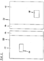
- FIG 2 illustrates a schematic top view of the heating plate according to a second embodiment of the present invention.
- the heating plate according to the second embodiment includes two heating elements 20 and 22.
- the heating plate and the heating elements 20 and 22 are rectangular.
- the heating elements 20 and 22 have the same sizes.
- the heating elements 20 and 22 are arranged side-by-side.
- An intermediate space is between said heating elements 20 and 22.
- Each of the heating elements 20 and 22 is subdivided into a number of rectangular heating zones 12, 14 and 18.
- the first heating zone 12 of each heating element 20 and 22 extends over the bigger area of the heating element 20 and 22, respectively.
- the second heating zone 14 of each heating element 20 and 22, respectively, extends over an area besides the intermediate space between said heating elements 20 and 22.
- the further heating zones 18 are arranged inside the first heating zone 12. In FIG 2 , only one further heating zone 18 is represented in each heating element 10. In general, one or more further heating zones 18 may be provided inside the first heating zone 12 of the heating element 10.
- the heating zones 12, 14 and 18 have different powers per area.
- the power per area of the second heating zones 14 is adapted in order to avoid or reduce hotspots in those outer portions of the heating elements 20 and 22, which are beside the intermediate space between the heating elements 20 and 22.
- FIG 3 illustrates a schematic top view of the heating plate according to a third embodiment of the present invention.
- the heating plate according to the third embodiment includes four heating elements 20, 22, 24 and 26.
- the heating plate and the heating elements 20, 22, 24 and 26 are rectangular.
- the heating elements 20, 22, 24 and 26 have the same sizes.
- the heating elements 20, 22, 24 and 26 are arranged as a two-by-two matrix. An intermediate space is between the neighboured heating elements 20, 22, 24 and 26.
- Each of the heating elements 20, 22, 24 and 26 is subdivided into a number of heating zones 12, 14 and 18.
- the first heating zone 12 of each heating element 20, 22, 24 and 26 extends over the bigger area of said heating element 20, 22, 24 and 26, respectively.
- the second heating zone 14 of each heating element 20, 22, 24 and 26 has an L-shaped area and is arranged besides the intermediate spaces between the neighboured heating elements 20, 22, 24 and 26, in each case.
- the further heating zones 18 are arranged inside the first heating zone 12. In FIG 3 , only one further heating zone 18 is represented in each heating element 10. In general, one or more further heating zones 18 may be provided inside the first heating zone 12 of the heating elements 20, 22, 24 and 26.
- the heating zones 12, 14 and 18 have different powers per area.
- the power per area of the second heating zones 14 is adapted in order to avoid or reduce hotspots in those outer portions of the heating elements 20, 22, 24 and 26, which are beside the intermediate spaces between the heating elements 20, 22, 24 and 26.
- FIG 4 illustrates a schematic sectional side view of the heating plate according to a fourth embodiment of the present invention.
- the fourth embodiment can be combined with the other three embodiments of the present invention.
- the heating plate includes a top panel 30, a graphite layer 32, a heating panel 34 and a supporting plate 36.
- the top panel 30, the graphite layer 32, the heating panel 34 and the supporting plate 36 are arranged one upon the other.
- a temperature sensor element 40 is provided for detecting the temperature on the top panel 30.
- the temperature sensor element 40 is pressed against the top panel 30 in order to obtain an exact detection of the temperature without latency or with a reduced latency.
- the heating panel 34 corresponds with the heating element 10, 20, 22, 24, 26 and/or with the heating zone 12, 14, 16, 18.
- the temperature sensor element 40 is formed as a mushroom.
- the head of the mushroom-shaped temperature sensor element 40 is pressed against the bottom side of the top panel 30.
- the shaft of the mushroom-shaped temperature sensor element 40 penetrates through the heating panel 14 and the supporting plate 16.
- the temperature sensor element 40 is directly pressed by the heating panel 14.
- the temperature sensor element 40 is indirectly pressed by pressing discs 38 via the supporting plate 16 against the top panel 10.
- the pressing discs 18 are fastened at the supporting plate 16 by a fastening bolt 42 and a screw nut 44 in each case.
- the area of the graphite layer 32 is bigger than the area of the heating panel 34. Further, the area of the graphite layer 32 is marginally smaller than the area of the top panel 30.
- the heating panel 34 extends below the top panel 30 only over the central portion of the top panel 30, but into the border areas of the top panel 30.
- the graphite layer 32 allows a heat transfer from the central portion to the border areas below the top panel 30.
- the graphite layer 32 is pressed against the top panel 30 by the pressing discs 38.
Landscapes
- Physics & Mathematics (AREA)
- Electromagnetism (AREA)
- Baking, Grill, Roasting (AREA)
Abstract
Description
- The present invention relates to a heating plate including at least one heating element. In particular, the present invention relates to a heating plate for cooking appliances.
- On a conventional heating plate the distribution of the power on the upper surface is non-uniform. In the central portion of the heating plate the power is higher than in the peripheral portions of said heating plate. In the worst case, hotspots may occur on the heating plate. A uniform temperature distribution is requested.
- It is an object of the present invention to provide a heating plate with an improved distribution of the heat on said heating plate.
- The object of the present invention is achieved by the heating plate according to claim 1.
- The heating plate according to the present invention includes at least one heating element, wherein:
- the at least one heating element is subdivided into a number of heating zones,
- the heating zones are formed as one or more horizontal heating panels,
- the heating zones are arranged at the same level, and
- the heating zones are provided for different heating powers per area according to a predetermined scheme in order to avoid or reduce hotspots on the heating plate.
- The core of the present invention is the subdivision of the heating into heating zones, wherein different heating powers per area are provided. The heating powers per area are adjusted in such a way that hotspots on the heating plate are avoided or reduced.
- In particular, the heating power per area of a heating zone in a border area of a single heating element is higher than or adjustable in excess of the heating power per area of a heating zone in a central portion of said heating element. In the border area of the heating element an extensive horizontal heat transfer occurs, so that the border area is clearly cooled down. The higher heating power per area in the border area compensates this effect.
- Preferably, there is an intermediate space between two neighboured heating elements.
- Further, the heating power per area of a heating zone besides the intermediate space may be adapted in order to avoid or reduce hotspots on the heating plate.
- According to a further embodiment of the present invention at least one smaller heating zone is arranged inside a larger heating zone. The heating power per area in the smaller heating zone can be adapted in order to avoid or reduce hotspots on the heating plate.
- For example, the at least one smaller heating zone is arranged in the central portion of the heating element.
- Further, the heating plate comprises a top panel, wherein the heating panels are arranged below said top panel.
- According to a preferred embodiment of the present invention a graphite layer is arranged between the top panel and the heating panels.
- In order to obtain a sufficient heat transfer the graphite layer is pressed against the top panel.
- In particular, the base area of the graphite layer extends in excess of the base area of the heating panel or heating panels, respectively, in order to allow a heat transfer to such portions of the top panel, which are spaced apart from the heating panel. This contributes to a uniform distribution of the heat on the heating plate.
- For example, the heating plate comprises at least one pressing disc fixed at a bottom side of said heating plate in order to press graphite layer against the top panel.
- At last, the heating plate may be provided for cooking appliances. In particular, the heating plate is provided for grilling purposes.
- Novel and inventive features of the present invention are set forth in the appended claims.
- The present invention will be described in further detail with reference to the drawings, in which
- FIG 1
- illustrates a schematic top view of a heating plate according to a first embodiment of the present invention,
- FIG 2
- illustrates a schematic top view of the heating plate according to a second embodiment of the present invention,
- FIG 3
- illustrates a schematic top view of the heating plate according to a third embodiment of the present invention, and
- FIG 4
- illustrates a schematic sectional side view of the heating plate according to a fourth embodiment of the present invention.
-
FIG 1 illustrates a schematic top view of a heating plate according to a first embodiment of the present invention. The heating plate according to the first embodiment includes oneheating element 10. The heating plate and theheating element 10 are rectangular. Theheating element 10 is subdivided into a number ofheating zones - A
first heating zone 12 extends over the border area of theheating element 10. Thus, thefirst heating zone 12 forms a rectangular frame of theheating element 10. - A
second heating zone 14 is arranged in a central portion of theheating element 10. Thesecond heating zone 14 is enclosed by thefirst heating zone 12. - Two
third heating zones 16 are arranged inside thesecond heating zone 14. Thethird heating zones 16 have rectangular forms. Thethird heating zones 16 are arranged inside a front portion and rear portion, respectively, of thesecond heating zone 14. - A number of
further heating zones 18 is arranged inside thesecond heating zone 14. Only onefurther heating zone 18 is represented inFIG 1 . In general, one or morefurther heating zones 18 may be provided on theheating element 10. The one or morefurther heating zones 18 are arranged between the twothird heating zones 16. - The
heating zones first heating zone 12 is relative high in order to compensate the increased thermal flow in the border area of theheating element 10. If the outer border area of thefirst heating zone 12 is not heated by a heating element from below, then a horizontal thermal flow from the inner area to the outer area is relative high. In this way, hotspots in the inner portion of theheating element 10 are avoided or reduced. -
FIG 2 illustrates a schematic top view of the heating plate according to a second embodiment of the present invention. The heating plate according to the second embodiment includes twoheating elements - The heating plate and the
heating elements heating elements heating elements heating elements heating elements rectangular heating zones - The
first heating zone 12 of eachheating element heating element second heating zone 14 of eachheating element heating elements further heating zones 18 are arranged inside thefirst heating zone 12. InFIG 2 , only onefurther heating zone 18 is represented in eachheating element 10. In general, one or morefurther heating zones 18 may be provided inside thefirst heating zone 12 of theheating element 10. - The
heating zones second heating zones 14 is adapted in order to avoid or reduce hotspots in those outer portions of theheating elements heating elements -
FIG 3 illustrates a schematic top view of the heating plate according to a third embodiment of the present invention. The heating plate according to the third embodiment includes fourheating elements - The heating plate and the
heating elements heating elements heating elements neighboured heating elements heating elements heating zones - The
first heating zone 12 of eachheating element heating element second heating zone 14 of eachheating element neighboured heating elements further heating zones 18 are arranged inside thefirst heating zone 12. InFIG 3 , only onefurther heating zone 18 is represented in eachheating element 10. In general, one or morefurther heating zones 18 may be provided inside thefirst heating zone 12 of theheating elements - The
heating zones second heating zones 14 is adapted in order to avoid or reduce hotspots in those outer portions of theheating elements heating elements -
FIG 4 illustrates a schematic sectional side view of the heating plate according to a fourth embodiment of the present invention. The fourth embodiment can be combined with the other three embodiments of the present invention. - The heating plate includes a
top panel 30, agraphite layer 32, aheating panel 34 and a supportingplate 36. Thetop panel 30, thegraphite layer 32, theheating panel 34 and the supportingplate 36 are arranged one upon the other. Atemperature sensor element 40 is provided for detecting the temperature on thetop panel 30. Thetemperature sensor element 40 is pressed against thetop panel 30 in order to obtain an exact detection of the temperature without latency or with a reduced latency. Theheating panel 34 corresponds with theheating element heating zone - The
temperature sensor element 40 is formed as a mushroom. The head of the mushroom-shapedtemperature sensor element 40 is pressed against the bottom side of thetop panel 30. The shaft of the mushroom-shapedtemperature sensor element 40 penetrates through theheating panel 14 and the supportingplate 16. Thetemperature sensor element 40 is directly pressed by theheating panel 14. Thetemperature sensor element 40 is indirectly pressed by pressingdiscs 38 via the supportingplate 16 against thetop panel 10. Thepressing discs 18 are fastened at the supportingplate 16 by afastening bolt 42 and ascrew nut 44 in each case. - The area of the
graphite layer 32 is bigger than the area of theheating panel 34. Further, the area of thegraphite layer 32 is marginally smaller than the area of thetop panel 30. Theheating panel 34 extends below thetop panel 30 only over the central portion of thetop panel 30, but into the border areas of thetop panel 30. Thegraphite layer 32 allows a heat transfer from the central portion to the border areas below thetop panel 30. Thegraphite layer 32 is pressed against thetop panel 30 by thepressing discs 38. - Although illustrative embodiments of the present invention have been described herein with reference to the accompanying drawings, it is to be understood that the present invention is not limited to those precise embodiments, and that various other changes and modifications may be affected therein by one skilled in the art without departing from the scope or spirit of the invention. All such changes and modifications are intended to be included within the scope of the invention as defined by the appended claims.
-
- 10
- heating element
- 12
- first heating zone
- 14
- second heating zone
- 16
- third heating zone
- 18
- further heating zone
- 20
- first heating element
- 22
- second heating element
- 24
- third heating element
- 26
- fourth heating element
- 30
- top panel
- 32
- graphite layer
- 34
- heating panel
- 36
- supporting plate
- 38
- pressing disc
- 40
- temperature sensor element
- 42
- fastening bolt
- 44
- screw nut
Claims (12)
- A heating plate including at least one heating element (10; 20, 22, 24, 26), wherein:- the at least one heating element (10; 20, 22, 24, 26) is subdivided into a number of heating zones (12, 14, 16, 18),- the heating zones (12, 14, 16, 18) are formed as one or more horizontal heating panels (34),- the heating zones (12, 14, 16, 18) are arranged at the same level, and- the heating zones (12, 14, 16, 18) are provided for different heating powers per area according to a predetermined scheme in order to avoid or reduce hotspots on the heating plate.
- The heating plate according to claim 1,
characterized in, that
the heating power per area of a heating zone (12) in a border area of a single heating element (10) is higher than or adjustable in excess of the heating power per area of a heating zone (14) in a central portion of said heating element (10). - The heating plate according to claim 1 or 2,
characterized in, that
there is an intermediate space between two neighboured heating elements (10; 20, 22, 24, 26). - The heating plate according to claim 3,
characterized in, that
the heating power per area of a heating zone (14) besides the intermediate space is adapted in order to avoid or reduce hotspots on the heating plate. - The heating plate according to any one of the preceding claims,
characterized in, that
at least one smaller heating zone (16, 18) is arranged inside a larger heating zone (12, 14). - The heating plate according to any one of the preceding claims,
characterized in, that
the at least one smaller heating zone (16, 18) is arranged in the central portion of the heating element (10). - The heating plate according to any one of the preceding claims,
characterized in, that
the heating plate comprises a top panel (30), wherein the heating panels (34) are arranged below said top panel (30). - The heating plate according to claim 7,
characterized in, that
a graphite layer (32) is arranged between the top panel (30) and the heating panels (34). - The heating plate according to claim 8,
characterized in, that
the graphite layer (32) is pressed against the top panel (30). - The heating plate according to claim 8 or 9,
characterized in, that
the base area of the graphite layer (32) extends in excess of the base area of the heating panel (34) or heating panels (34), respectively, in order to allow a heat transfer to such portions of the top panel (30), which are spaced apart from the heating panel (34). - The heating plate according to any one of the claims 8 to 10,
characterized in, that
the heating plate comprises at least one pressing disc (38) fixed at a bottom side of said heating plate in order to press graphite layer (32) against the top panel (30). - The heating plate according to any one of the preceding claims,
characterized in, that
the heating plate is provided for cooking appliances.
Priority Applications (1)
| Application Number | Priority Date | Filing Date | Title |
|---|---|---|---|
| EP12156427.2A EP2632229A1 (en) | 2012-02-22 | 2012-02-22 | A heating plate including at least one heating element |
Applications Claiming Priority (1)
| Application Number | Priority Date | Filing Date | Title |
|---|---|---|---|
| EP12156427.2A EP2632229A1 (en) | 2012-02-22 | 2012-02-22 | A heating plate including at least one heating element |
Publications (1)
| Publication Number | Publication Date |
|---|---|
| EP2632229A1 true EP2632229A1 (en) | 2013-08-28 |
Family
ID=45656346
Family Applications (1)
| Application Number | Title | Priority Date | Filing Date |
|---|---|---|---|
| EP12156427.2A Withdrawn EP2632229A1 (en) | 2012-02-22 | 2012-02-22 | A heating plate including at least one heating element |
Country Status (1)
| Country | Link |
|---|---|
| EP (1) | EP2632229A1 (en) |
Citations (6)
| Publication number | Priority date | Publication date | Assignee | Title |
|---|---|---|---|---|
| CN2222419Y (en) * | 1995-06-12 | 1996-03-13 | 张书绅 | Thermal-insulating warming plate for dining table |
| JPH09190879A (en) * | 1996-01-08 | 1997-07-22 | Matsushita Electric Ind Co Ltd | Induction heating cooker |
| GB2353456A (en) * | 1999-08-13 | 2001-02-21 | Strix Ltd | Minimising stress in thick film heating element |
| US20060096972A1 (en) * | 2004-10-28 | 2006-05-11 | Kyocera Corporation | Heater, wafer heating apparatus and method for manufacturing heater |
| EP1988750A1 (en) * | 2006-02-20 | 2008-11-05 | Covalent Materials Corporation | Planar heater |
| US20110132896A1 (en) * | 2009-12-08 | 2011-06-09 | Therm-X Of California | Heater plate with embedded hyper-conductive thermal diffusion layer for increased temperature rating and uniformity |
-
2012
- 2012-02-22 EP EP12156427.2A patent/EP2632229A1/en not_active Withdrawn
Patent Citations (6)
| Publication number | Priority date | Publication date | Assignee | Title |
|---|---|---|---|---|
| CN2222419Y (en) * | 1995-06-12 | 1996-03-13 | 张书绅 | Thermal-insulating warming plate for dining table |
| JPH09190879A (en) * | 1996-01-08 | 1997-07-22 | Matsushita Electric Ind Co Ltd | Induction heating cooker |
| GB2353456A (en) * | 1999-08-13 | 2001-02-21 | Strix Ltd | Minimising stress in thick film heating element |
| US20060096972A1 (en) * | 2004-10-28 | 2006-05-11 | Kyocera Corporation | Heater, wafer heating apparatus and method for manufacturing heater |
| EP1988750A1 (en) * | 2006-02-20 | 2008-11-05 | Covalent Materials Corporation | Planar heater |
| US20110132896A1 (en) * | 2009-12-08 | 2011-06-09 | Therm-X Of California | Heater plate with embedded hyper-conductive thermal diffusion layer for increased temperature rating and uniformity |
Similar Documents
| Publication | Publication Date | Title |
|---|---|---|
| US8530795B2 (en) | Electric cooking apparatus | |
| JP6069501B2 (en) | Modular double-sided grill | |
| US20150122137A1 (en) | Cooking pot and lid thereof | |
| CN201782623U (en) | Multifunctional electronic oven | |
| WO2009007781A3 (en) | Multi-zone composite cooking griddle with unitary thermally conductive plate | |
| EP1946685B1 (en) | Grilling plate | |
| US20050040171A1 (en) | Multi clad cookware | |
| CA2582453A1 (en) | Modular layered heater system | |
| JP4462868B2 (en) | Heating device | |
| JP2014521577A5 (en) | ||
| US7726296B2 (en) | Drywell table | |
| CN102256518A (en) | Temperature control display rack | |
| KR101956654B1 (en) | Insulating pot bottom for stockpots | |
| EP3547883B1 (en) | Continuous cooking surface with individually controllable heating zones | |
| EP2822357B1 (en) | Power saving induction cooking plate, cooking vessel and induction cooking arrangement | |
| KR20070085343A (en) | Food serving bar | |
| EP1530902A1 (en) | Cooking plate particularly for food ovens | |
| CN204795674U (en) | Coil plate frame, coil plate and induction cooker | |
| US10772465B2 (en) | Continuous cooking surface with individually controllable heating zones | |
| JP2017113324A (en) | Kitchen counter | |
| JP2011067391A (en) | Baked sweet potato machine | |
| CN221149960U (en) | Semiconductor wafer heating and baking equipment | |
| RU2266200C1 (en) | Press for thermoforming of product | |
| TWI648023B (en) | Pot and method for manufacturing the same | |
| CN209489076U (en) | Radiating ribs structure |
Legal Events
| Date | Code | Title | Description |
|---|---|---|---|
| PUAI | Public reference made under article 153(3) epc to a published international application that has entered the european phase |
Free format text: ORIGINAL CODE: 0009012 |
|
| AK | Designated contracting states |
Kind code of ref document: A1 Designated state(s): AL AT BE BG CH CY CZ DE DK EE ES FI FR GB GR HR HU IE IS IT LI LT LU LV MC MK MT NL NO PL PT RO RS SE SI SK SM TR |
|
| AX | Request for extension of the european patent |
Extension state: BA ME |
|
| 17P | Request for examination filed |
Effective date: 20140123 |
|
| RBV | Designated contracting states (corrected) |
Designated state(s): AL AT BE BG CH CY CZ DE DK EE ES FI FR GB GR HR HU IE IS IT LI LT LU LV MC MK MT NL NO PL PT RO RS SE SI SK SM TR |
|
| 17Q | First examination report despatched |
Effective date: 20151109 |
|
| STAA | Information on the status of an ep patent application or granted ep patent |
Free format text: STATUS: THE APPLICATION IS DEEMED TO BE WITHDRAWN |
|
| 18D | Application deemed to be withdrawn |
Effective date: 20160322 |