EP2632124A1 - Edge closure cover - Google Patents
Edge closure cover Download PDFInfo
- Publication number
- EP2632124A1 EP2632124A1 EP12156975.0A EP12156975A EP2632124A1 EP 2632124 A1 EP2632124 A1 EP 2632124A1 EP 12156975 A EP12156975 A EP 12156975A EP 2632124 A1 EP2632124 A1 EP 2632124A1
- Authority
- EP
- European Patent Office
- Prior art keywords
- cover
- edge surface
- flap portion
- electronic device
- mobile electronic
- Prior art date
- Legal status (The legal status is an assumption and is not a legal conclusion. Google has not performed a legal analysis and makes no representation as to the accuracy of the status listed.)
- Withdrawn
Links
- CWYNVVGOOAEACU-UHFFFAOYSA-N Fe2+ Chemical compound [Fe+2] CWYNVVGOOAEACU-UHFFFAOYSA-N 0.000 claims description 20
- 239000002184 metal Substances 0.000 claims description 20
- 239000000463 material Substances 0.000 description 7
- 230000001413 cellular effect Effects 0.000 description 2
- IRLPACMLTUPBCL-KQYNXXCUSA-N 5'-adenylyl sulfate Chemical compound C1=NC=2C(N)=NC=NC=2N1[C@@H]1O[C@H](COP(O)(=O)OS(O)(=O)=O)[C@@H](O)[C@H]1O IRLPACMLTUPBCL-KQYNXXCUSA-N 0.000 description 1
- 241001272720 Medialuna californiensis Species 0.000 description 1
- 239000004973 liquid crystal related substance Substances 0.000 description 1
- 238000012986 modification Methods 0.000 description 1
- 230000004048 modification Effects 0.000 description 1
- 230000000717 retained effect Effects 0.000 description 1
Images


Classifications
-
- H—ELECTRICITY
- H04—ELECTRIC COMMUNICATION TECHNIQUE
- H04M—TELEPHONIC COMMUNICATION
- H04M1/00—Substation equipment, e.g. for use by subscribers
- H04M1/02—Constructional features of telephone sets
- H04M1/04—Supports for telephone transmitters or receivers
- H04M1/05—Supports for telephone transmitters or receivers specially adapted for use on head, throat or breast
-
- A—HUMAN NECESSITIES
- A45—HAND OR TRAVELLING ARTICLES
- A45C—PURSES; LUGGAGE; HAND CARRIED BAGS
- A45C11/00—Receptacles for purposes not provided for in groups A45C1/00-A45C9/00
-
- A—HUMAN NECESSITIES
- A45—HAND OR TRAVELLING ARTICLES
- A45C—PURSES; LUGGAGE; HAND CARRIED BAGS
- A45C11/00—Receptacles for purposes not provided for in groups A45C1/00-A45C9/00
- A45C11/002—Receptacles for purposes not provided for in groups A45C1/00-A45C9/00 for storing portable handheld communication devices, e.g. pagers or smart phones
-
- A—HUMAN NECESSITIES
- A45—HAND OR TRAVELLING ARTICLES
- A45C—PURSES; LUGGAGE; HAND CARRIED BAGS
- A45C13/00—Details; Accessories
- A45C13/10—Arrangement of fasteners
- A45C13/1069—Arrangement of fasteners magnetic
Definitions
- a mobile electronic device can be a cellular phone, including a smart phone, a dedicated personal digital assistant (PDA) with or without phone or data capabilities, an electronic reading device, a tablet computer, a digital media player, or any other mobile device.
- PDA personal digital assistant
- the terms "mobile device,” “hand held device” and “hand set” are interchangeable, both regarding to electronic devices available as information stores for personal contacts, calendar appointments, and the like. Since users often carry their mobile electronic devices with them throughout the day, the most popular covers for containing and protecting the devices are those that are compact and easy to use. Some covers have flaps that are retained closed with magnetic clasps, having one or more magnets.
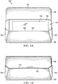
- FIG. 1A is a front view of a cover for a mobile electronic device with the cover shown open and the mobile electronic device inside.
- FIG. 1B is a front view of the cover shown closed.
- FIG. 2B is a half, side cross-sectional detail view of the cover of FIGS. 1A and 1B showing the magnetic clasp.
- FIG. 3 is a front view of the cover of FIGS. 1A and 1B with the cover shown closed and material of the cover cut-away to show parts of the magnetic clasp.
- FIG. 1A is a front view of an example cover 100 for a mobile electronic device 110 with the cover 100 shown open and the mobile electronic device 110 inside.
- FIG. 1B is a front view of the cover 100 shown closed.
- the example cover 100 is but one example of a number of different forms of covers that the concepts herein can be applied to.
- the cover can take the form of a case, a skin, a holster, a pocket, a sleeve, a slip case, an envelope, a folio, and/or another form.
- the cover 100 defines a cavity 155 for receiving the mobile electronic device 110, and has a flap portion 140 that is changeable from open, shown in FIG. 1A , to closed, shown in FIG. 1B .
- the cover 100 includes a magnetic clasp that holds the flap portion 140 closed with the flap portion 140 edge to edge with another portion of the cover 100.
- the mobile electronic device 110 can be hand held and can be a cellular phone, including a smart phone, a dedicated personal digital assistant (PDA) with or without phone or data capabilities, an electronic reading device, a tablet computer, a digital media player, or any other mobile device.
- PDA personal digital assistant
- the terms "mobile device,” “hand held device” and “hand set” are interchangeable, regarding to electronic devices available as information stores for personal contacts, calendar appointments, and the like.
- the mobile device can have a battery, enabling the device to be operated without a power cord.
- many mobile devices wirelessly connect to the public Internet to allow for the sending and receiving of e-mail. Such mobile devices may also provide more general Internet access, such as access to the World Wide Web.
- the mobile device 110 may be designed to operate with the General Packet Radio Service (GPRS) mobile data communication networks and may also be designed to operate with any of a variety of voice communication networks, such as AMPS, TDMA, CDMA, PCS, GSM, etc. Other types of data and voice networks, both separate and integrated, may also be utilized with the mobile device 110.
- GPRS General Packet Radio Service
- the mobile device 110 is a two-way RF communication device having voice and data communication capabilities.
- the mobile device 110 can have the capability to communicate with other mobile devices or computer systems via the Internet.
- the example cover 100 is made of a single, continuous piece of material, but could be made of multiple pieces.
- the material is thin and initially flat and has an edge or end surface that is perpendicular (substantially or precisely) to the plane of the material.
- a bottom flap portion 150 and side flap portions 160, 162 are folded together and attached to one another to define a body portion of the cover 100 having an interior cavity 155 that receives and circumscribes the mobile electronic device 110.
- the side flap portions 160, 162 can be omitted.
- the bottom flap portion 150 has an inward facing interior surface, an outward facing exterior surface, and an end or edge surface 152 spans between the interior surface and the exterior surface (i.e., perpendicular to the plane of the material forming the bottom flap portion 150).
- the edge surface 152 defines a portion of the perimeter of the opening to the cavity 155.
- top flap portion 140 and bottom flap portion 150 do not overlap.
- the exterior surface of the top flap portion 140 is flush with the exterior surface of the bottom flap portion 150 when the top flap portion 140 is closed.
- Such a non-overlapping edge surface to edge surface closed configuration is more compact than if the top flap portion 140 and bottom flap portion 150 were to overlap.
- the top flap portion 140 and bottom flap portion 150 do not overlap, they do not create a pressure point on the device 110.
- FIG. 2B is a half, side cross-sectional detail view of the cover of FIGS. 1A and 1B taken through the top flap portion 140 and bottom flap portion 150, intermediate the sides of the cover 100.
- the view shows a magnetic clasp having a first part 154 in the bottom flap portion 150 and a second part 144 in the top flap portion 140.
- the first part 154 magnetically clasps to the second part 144 when the edge surface 142 of the flap portion 140 is adjacent to the edge surface 152 of the bottom flap portion 150, and holds the two flap portions 140, 150 together and the top flap portion 140 closed.
- Each is arranged so its edge surface coincides with an edge surface 142, 152.
- a portion, such as an edge surface, of the one or both magnetic clasp parts 144, 154 is exposed at the edge surface 142, 152 or the magnetic clasp parts 144, 154 are wholly embedded within the top flap portion 140 and/or bottom flap portion 150.
- the remainder of the magnetic clasp parts 144, 154 can be embedded in the top flap portion 140 and/or bottom flap portion 150, or other parts of the magnetic clasp parts 144, 154 can be exposed.
- FIG. 3 is a front view of the cover 100 cut away to show the magnetic clasp parts 144, 154.
- the depicted example shows three different arrangements of possible magnetic clasps.
- Magnetic clasp parts 144a, 154a illustrate parts that are both magnets.
- Magnetic clasp parts 144b, 154b illustrate parts where one part is a magnet and the other part is ferrous metal.
- Magnetic clasp parts 144c, 154c illustrate parts made of a ferrous metal adjacent or at the edge surface 142, 152 that is magnetized by a magnet 146, 156 adjacent and abutting the ferrous metal, but apart from the edge surface 142, 152.
- a given cover 100 can include one pair of magnetic clasp parts 144, 154 or multiple pairs of parts 144, 154.
- all the pairs can be of the same arrangement, or some or all pairs can be of a different arrangement.
- the magnets and/or ferrous metal in the magnetic clasp parts 144, 154 can be of different shapes, including rectangular strips, square, half-moon and/or other shapes. If multiple magnetic clasps are used, all clasps can include parts 144, 154 of the same shape or some or all of the clasps can include parts 144, 154 of different shapes. Within a given magnetic clasp, the parts 144, 154 can be of the same shape or each part can be of a different configuration.
- the magnets in the magnetic clasp parts 144, 154 can be magnetized with their poles on edge surfaces of the magnets, in the plane of the top flap portion 140 and bottom flap portion 150, rather than on face surfaces of the magnets, perpendicular to the plane of the top flap portion 140 and bottom flap portion 150. With the poles on the edge surfaces of the magnets, the poles are aligned when the top flap portion 140 is closed, and the resulting magnetic attraction (whether both magnetic clasp parts 144, 154 are magnets or one is a ferrous metal) is greater than if the poles of the magnets were in the face surfaces of the magnets.
- any shield can be reduced over that needed for magnets with face poles or, in certain instances, the shield may be omitted.
- the configurations of magnetic clasp parts 144, 154 with a magnet adjacent or abutting a ferrous metal can likewise have poles on the edges surfaces of the magnets that are adj acent or abutting the ferrous metal.
- FIG. 4 is a front view of yet another cover for a mobile electronic device with the cover shown closed.
- the edge surfaces 142, 152 have an interlocking non-straight shape, where the bottom flap portion 150 protrudes into a recessed area of the top flap portion 140.
- the non-straight shape can be configured to facilitate alignment of the top flap portion 140 with the bottom flap portion 150 when the cover is closed.
- the ferrous metal can conform to the non-straight shape of the edge surfaces 142, 152. Furthermore, in certain instances, the ferrous metal can extend the length (partially, substantially or entirely) of the edge surfaces 142, 152. Because ferrous metal is malleable, it will be less prone to breaking than a (more brittle) magnet of the same size.
- the concepts herein encompass a cover for a mobile electronic device that has a flap or flaps that, when closed, meet edge surface to edge surface with an edge surface of another flap or another part of the cover.
- the edge surfaces each contain a part of a magnetic clasp to clasp the edge surfaces together, and the flap or flaps closed.
- Such a configuration is more compact than configurations having flaps that overlap another part of the cover, and additionally do not create a pressure point that may bear on the device.
Landscapes
- Health & Medical Sciences (AREA)
- Otolaryngology (AREA)
- Engineering & Computer Science (AREA)
- Signal Processing (AREA)
- Telephone Set Structure (AREA)
- Casings For Electric Apparatus (AREA)
Abstract
Description
- A mobile electronic device can be a cellular phone, including a smart phone, a dedicated personal digital assistant (PDA) with or without phone or data capabilities, an electronic reading device, a tablet computer, a digital media player, or any other mobile device. In many instances, the terms "mobile device," "hand held device" and "hand set" are interchangeable, both regarding to electronic devices available as information stores for personal contacts, calendar appointments, and the like. Since users often carry their mobile electronic devices with them throughout the day, the most popular covers for containing and protecting the devices are those that are compact and easy to use. Some covers have flaps that are retained closed with magnetic clasps, having one or more magnets.
-
FIG. 1A is a front view of a cover for a mobile electronic device with the cover shown open and the mobile electronic device inside. -
FIG. 1B is a front view of the cover shown closed. -
FIG. 2A is a side view of the cover ofFIGS. 1A and 1B shown closed. -
FIG. 2B is a half, side cross-sectional detail view of the cover ofFIGS. 1A and 1B showing the magnetic clasp. -
FIG. 3 is a front view of the cover ofFIGS. 1A and 1B with the cover shown closed and material of the cover cut-away to show parts of the magnetic clasp. -
FIG. 4 is a front view of yet another cover for a mobile electronic device with the cover shown closed and material of the cover cut-away to show parts of the magnetic clasp. - Like reference symbols in the various drawings indicate like elements.
-
FIG. 1A is a front view of anexample cover 100 for a mobileelectronic device 110 with thecover 100 shown open and the mobileelectronic device 110 inside.FIG. 1B is a front view of thecover 100 shown closed. Theexample cover 100 is but one example of a number of different forms of covers that the concepts herein can be applied to. For example, the cover can take the form of a case, a skin, a holster, a pocket, a sleeve, a slip case, an envelope, a folio, and/or another form. As will be described in more detail below, thecover 100 defines acavity 155 for receiving the mobileelectronic device 110, and has aflap portion 140 that is changeable from open, shown inFIG. 1A , to closed, shown inFIG. 1B . Thecover 100 includes a magnetic clasp that holds theflap portion 140 closed with theflap portion 140 edge to edge with another portion of thecover 100. - The mobile
electronic device 110 can be hand held and can be a cellular phone, including a smart phone, a dedicated personal digital assistant (PDA) with or without phone or data capabilities, an electronic reading device, a tablet computer, a digital media player, or any other mobile device. In many instances, the terms "mobile device," "hand held device" and "hand set" are interchangeable, regarding to electronic devices available as information stores for personal contacts, calendar appointments, and the like. The mobile device can have a battery, enabling the device to be operated without a power cord. Additionally, many mobile devices wirelessly connect to the public Internet to allow for the sending and receiving of e-mail. Such mobile devices may also provide more general Internet access, such as access to the World Wide Web. For example, themobile device 110 may be designed to operate with the General Packet Radio Service (GPRS) mobile data communication networks and may also be designed to operate with any of a variety of voice communication networks, such as AMPS, TDMA, CDMA, PCS, GSM, etc. Other types of data and voice networks, both separate and integrated, may also be utilized with themobile device 110. - In certain instances, the
mobile device 110 is a two-way RF communication device having voice and data communication capabilities. In addition, themobile device 110 can have the capability to communicate with other mobile devices or computer systems via the Internet. - The
mobile device 110 includes afront frame 130 and ascreen 120. A forward facing surface of thefront frame 130 forms the forward facing surface of themobile device 110. A back cover 115 (shown inFIG. 2A ) is attached to the back side of the front face and a backward facing surface of theback cover 115 defines the back surface of themobile device 110. Thefront frame 130 cooperates with theback cover 115 to house inner components of themobile device 110. - The
screen 120 can be both an input device (i.e., a touch sensitive device) and an output device (i.e., a display). In some embodiments, thescreen 120 is a light emitting diode (LED) backlit liquid crystal display (LCD) with multi-touch control functions. Some of these features may be omitted in other examples. For example, thescreen 120 may lack the multi-touch control functions, or thescreen 120 may lack the LED backlit feature. In some embodiments, themobile device 110 may include additional features, such as a front camera. - The
example cover 100 is made of a single, continuous piece of material, but could be made of multiple pieces. The material is thin and initially flat and has an edge or end surface that is perpendicular (substantially or precisely) to the plane of the material. Abottom flap portion 150 andside flap portions cover 100 having aninterior cavity 155 that receives and circumscribes the mobileelectronic device 110. In other instances, for example a folio cover, the side flapportions bottom flap portion 150 has an inward facing interior surface, an outward facing exterior surface, and an end oredge surface 152 spans between the interior surface and the exterior surface (i.e., perpendicular to the plane of the material forming the bottom flap portion 150). Theedge surface 152 defines a portion of the perimeter of the opening to thecavity 155. - The
top flap portion 140 is coupled to thebottom flap portion 150, and can fold from open, shown inFIG. 1A , to closed, shown inFIG. 1B . When thetop flap portion 140 is open, theinterior cavity 155 is open and the mobileelectronic device 110 can be inserted and removed from theinterior cavity 155 of thecover 100. When thetop flap portion 140 is closed, it covers the opening to thecavity 155, as well as the mobileelectronic device 110, and retains the mobileelectronic device 110 in theinterior cavity 155 of thecover 100.FIG. 2A is a side view of the cover ofFIGS. 1A and 1B shown closed. As seen inFIG. 2A , thetop flap portion 140 only partially covers the opening to thecavity 155 and only partially covers the mobile electronic device 110 (leaving openings on the end). In other instances, the top flap could fully cover the opening to thecavity 155 and/or the mobileelectronic device 110 or could take the form of a strap that leaves an even larger portion of the opening to theinterior cavity 155 uncovered. Like thebottom flap portion 150, thetop flap portion 140 has an interior surface that is inward facing when the flap portion is closed, an exterior surface that is outward facing when the flap is closed, and an end or edge surface 142 (FIG. 2B ) spanning between the interior surface and the exterior surface (i.e., perpendicular to the plane of the material forming the top flap portion 140). When thetop flap portion 140 is closed, theedge surface 142 resides meeting theedge surface 152, adjacent to and in certain instances abutting theedge surface 152. Additionally, when thetop flap portion 140 is closed, thetop flap portion 140 andbottom flap portion 150 do not overlap. As seen inFIG. 2A , the exterior surface of thetop flap portion 140 is flush with the exterior surface of thebottom flap portion 150 when thetop flap portion 140 is closed. Such a non-overlapping edge surface to edge surface closed configuration is more compact than if thetop flap portion 140 andbottom flap portion 150 were to overlap. Furthermore, because thetop flap portion 140 andbottom flap portion 150 do not overlap, they do not create a pressure point on thedevice 110. -
FIG. 2B is a half, side cross-sectional detail view of the cover ofFIGS. 1A and 1B taken through thetop flap portion 140 andbottom flap portion 150, intermediate the sides of thecover 100. The view shows a magnetic clasp having afirst part 154 in thebottom flap portion 150 and asecond part 144 in thetop flap portion 140. Thefirst part 154 magnetically clasps to thesecond part 144 when theedge surface 142 of theflap portion 140 is adjacent to theedge surface 152 of thebottom flap portion 150, and holds the twoflap portions top flap portion 140 closed. - Both of the
magnetic clasp parts part 144, 154) with their poles aligned so that the magnets magnetically attract to one another and effectuate the clasping. Alternately, in some instances, one part (either thefirst part 154 in thebottom flap portion 150 or thesecond part 144 in the top flap portion 140) can include one or more magnets and the other part includes only ferrous metal that is magnetically attracted to the magnets. As seen inFIG. 2B , themagnetic clasp parts top flap portion 140 andbottom flap portion 150, respectively. Each is arranged so its edge surface coincides with anedge surface magnetic clasp parts edge surface magnetic clasp parts top flap portion 140 and/orbottom flap portion 150. The remainder of themagnetic clasp parts top flap portion 140 and/orbottom flap portion 150, or other parts of themagnetic clasp parts -
FIG. 3 is a front view of thecover 100 cut away to show themagnetic clasp parts Magnetic clasp parts Magnetic clasp parts Magnetic clasp parts edge surface magnet edge surface cover 100 can include one pair ofmagnetic clasp parts parts cover 100 has multiple pairs ofparts magnetic clasp parts parts parts parts - The magnets in the
magnetic clasp parts top flap portion 140 andbottom flap portion 150, rather than on face surfaces of the magnets, perpendicular to the plane of thetop flap portion 140 andbottom flap portion 150. With the poles on the edge surfaces of the magnets, the poles are aligned when thetop flap portion 140 is closed, and the resulting magnetic attraction (whether bothmagnetic clasp parts device 110. For example, in certain instances, the thickness of any shield can be reduced over that needed for magnets with face poles or, in certain instances, the shield may be omitted. The configurations ofmagnetic clasp parts - The
edge surface 142 of thetop flap portion 140 and theedge surface 152 of thebottom flap portion 150 need not be straight as inFIGS. 1-3 .FIG. 4 is a front view of yet another cover for a mobile electronic device with the cover shown closed. In this view, the edge surfaces 142, 152 have an interlocking non-straight shape, where thebottom flap portion 150 protrudes into a recessed area of thetop flap portion 140. The non-straight shape can be configured to facilitate alignment of thetop flap portion 140 with thebottom flap portion 150 when the cover is closed. While such instances can use any configuration of magnetic clasp described above, if themagnetic clasp parts - Of note, although the concepts herein have been described with respect to a cover having a top flap portion that is clasped to a bottom flap portion, the concepts are applicable to many other configurations. For example, the concepts could be applied to side flaps, pockets, accessory loops and/or other aspects of a mobile electronic device cover.
- As is apparent from the discussion above, the concepts herein encompass a cover for a mobile electronic device that has a flap or flaps that, when closed, meet edge surface to edge surface with an edge surface of another flap or another part of the cover. The edge surfaces each contain a part of a magnetic clasp to clasp the edge surfaces together, and the flap or flaps closed. Such a configuration is more compact than configurations having flaps that overlap another part of the cover, and additionally do not create a pressure point that may bear on the device.
- A number of variations have been described. Nevertheless, it will be understood that various modifications may be made. Accordingly, other variations are within the scope of the following claims.
Claims (20)
- A cover for a mobile electronic device, comprising:a body portion defining an interior cavity for receiving the mobile electronic device, the body portion around an opening to the cavity having an inward facing interior surface, an outward facing exterior surface and an edge surface spanning between the interior surface and the exterior surface;a flap portion coupled to the body portion and closeable to at least partially cover the opening to the cavity, the flap portion having an interior surface that is inward facing when the flap portion is closed, an exterior surface that is outward facing when the flap is closed, and an edge surface spanning between the interior surface and the exterior surface, and the edge surface of the flap portion meeting the edge surface of the body portion when the flap portion is closed; anda magnetic clasp having a first part in the body portion that magnetically clasps to a second part in the flap portion when the edge surface of the flap portion is meeting the edge surface of the body portion.
- The cover of claim 1, where the flap portion does not overlap the body portion when the flap portion is closed.
- The cover of claim 1, where the exterior surface of the flap portion is flush with the exterior surface of the body portion when the flap portion is closed.
- The cover of claim 1, where at least one of the first part or the second part comprises a magnet having a pole at an edge surface of the magnet, the edge surface of the magnet is adjacent the edge surface of the body portion or the flap portion.
- The cover of claim 4, where the magnet is planar and embedded within the body portion or the flap portion.
- The cover of claim 4, where at least one of the first part or the second part comprises a ferrous metal.
- The cover of claim 1, where at least one of the first part or the second part comprises:a ferrous metal adjacent the edge surface of the body portion or the flap portion; anda magnet adj acent the ferrous metal.
- The cover of claim 7, where the magnet has a polarized edge surface abutting the ferrous metal.
- The cover of claim 7, where the ferrous metal extends substantially an entire length of the edge surface of the flap portion residing adjacent the edge surface of the body portion when the flap portion is closed.
- The cover of claim 1, where the edge surface of the flap portion has an interlocking shape with the edge surface of the body portion.
- The cover of claim 1, where the cavity is configured to circumscribe the mobile electronic device.
- A method, comprising:receiving a mobile electronic device in a mobile electronic device cover; andmagnetically clasping an edge surface of a flap portion of the cover to an edge surface of another part of the cover with the edge surfaces meeting.
- The method of claim 12, where magnetically clasping an edge surface of a flap portion of the cover to an edge surface of another part of the cover with the edge surfaces meeting, comprises magnetically clasping the edge surface of the flap portion of the cover to the edge surface of another part of the cover with the edge surfaces abutting and not overlapping.
- The method of claim 12, where magnetically clasping comprises magnetically attracting a first part of a magnetic clasp with a second part of the magnetic clasp when a pole of the first part of the magnetic clasp is aligned with an opposing pole of the second part of the magnetic clasp.
- A mobile electronic device cover, comprising:a first cover portion having a first edge surface along a perimeter thereof;a second cover portion having a second edge surface along a perimeter thereof; anda magnetic clasp having a first part in the first portion of the cover adj acent the first edge surface and a second part in the second portion of the cover adjacent the second edge surface and adapted to magnetically hold the first edge surface meeting the second edge surface.
- The mobile electronic device cover of claim 15, where the magnetic clasp is adapted to magnetically hold the first edge surface meeting the second edge surface when the first cover portion and the second cover portion are not overlapping.
- The mobile electronic device cover of claim 15, where the first part comprises:a ferrous metal adjacent the edge surface of the first cover portion; anda magnet abutting the ferrous metal.
- The mobile electronic device cover of claim 17, where the ferrous metal extends substantially an entire length of the edge surface of the first cover portion.
- The mobile electronic device cover of claim 15, where the edge surface of the first cover portion has an interlocking shape with the edge surface of the second cover portion.
- The mobile electronic device cover of claim 15, where the magnetic clasp comprises at least one magnet that is planar and embedded within the first cover portion or the second cover portion portion.
Priority Applications (2)
| Application Number | Priority Date | Filing Date | Title |
|---|---|---|---|
| EP12156975.0A EP2632124A1 (en) | 2012-02-24 | 2012-02-24 | Edge closure cover |
| CA2802571A CA2802571C (en) | 2012-02-24 | 2013-01-17 | Edge closure cover |
Applications Claiming Priority (1)
| Application Number | Priority Date | Filing Date | Title |
|---|---|---|---|
| EP12156975.0A EP2632124A1 (en) | 2012-02-24 | 2012-02-24 | Edge closure cover |
Publications (1)
| Publication Number | Publication Date |
|---|---|
| EP2632124A1 true EP2632124A1 (en) | 2013-08-28 |
Family
ID=45656727
Family Applications (1)
| Application Number | Title | Priority Date | Filing Date |
|---|---|---|---|
| EP12156975.0A Withdrawn EP2632124A1 (en) | 2012-02-24 | 2012-02-24 | Edge closure cover |
Country Status (2)
| Country | Link |
|---|---|
| EP (1) | EP2632124A1 (en) |
| CA (1) | CA2802571C (en) |
Citations (8)
| Publication number | Priority date | Publication date | Assignee | Title |
|---|---|---|---|---|
| US3716091A (en) * | 1970-09-14 | 1973-02-13 | A Gaines | Magnetic closure |
| DE29707519U1 (en) * | 1997-04-25 | 1997-07-31 | Hewerer, Jens, Dipl.-Ing., 01237 Dresden | Fastener closure |
| GB2363159A (en) * | 2000-06-09 | 2001-12-12 | Anchor Magnets Ltd | Flexible magnetic strip |
| FR2862948A1 (en) * | 2003-11-27 | 2005-06-03 | Lorenz Baumer | Case for presenting and/or protecting e.g. jewel, has magnets embedded on lower side of base in symmetry with magnets embedded on lateral walls of cover, where magnets are respectively oriented on opposite sides |
| US20060183518A1 (en) * | 2005-02-17 | 2006-08-17 | Bernard Emano | System for securing a cellular phone and viewing information window |
| KR20080002166U (en) * | 2006-12-21 | 2008-06-25 | 엘지전자 주식회사 | Case of mobile terminal |
| US20080156833A1 (en) * | 2006-12-29 | 2008-07-03 | Usa Wireless Solutions | Case for portable electronic devices having a magnetically shielded fastener |
| US20090095751A1 (en) * | 2007-10-12 | 2009-04-16 | Brian Hamlin | Utility pocket with magnetic closure |
-
2012
- 2012-02-24 EP EP12156975.0A patent/EP2632124A1/en not_active Withdrawn
-
2013
- 2013-01-17 CA CA2802571A patent/CA2802571C/en not_active Expired - Fee Related
Patent Citations (8)
| Publication number | Priority date | Publication date | Assignee | Title |
|---|---|---|---|---|
| US3716091A (en) * | 1970-09-14 | 1973-02-13 | A Gaines | Magnetic closure |
| DE29707519U1 (en) * | 1997-04-25 | 1997-07-31 | Hewerer, Jens, Dipl.-Ing., 01237 Dresden | Fastener closure |
| GB2363159A (en) * | 2000-06-09 | 2001-12-12 | Anchor Magnets Ltd | Flexible magnetic strip |
| FR2862948A1 (en) * | 2003-11-27 | 2005-06-03 | Lorenz Baumer | Case for presenting and/or protecting e.g. jewel, has magnets embedded on lower side of base in symmetry with magnets embedded on lateral walls of cover, where magnets are respectively oriented on opposite sides |
| US20060183518A1 (en) * | 2005-02-17 | 2006-08-17 | Bernard Emano | System for securing a cellular phone and viewing information window |
| KR20080002166U (en) * | 2006-12-21 | 2008-06-25 | 엘지전자 주식회사 | Case of mobile terminal |
| US20080156833A1 (en) * | 2006-12-29 | 2008-07-03 | Usa Wireless Solutions | Case for portable electronic devices having a magnetically shielded fastener |
| US20090095751A1 (en) * | 2007-10-12 | 2009-04-16 | Brian Hamlin | Utility pocket with magnetic closure |
Also Published As
| Publication number | Publication date |
|---|---|
| CA2802571A1 (en) | 2013-08-24 |
| CA2802571C (en) | 2015-05-19 |
Similar Documents
| Publication | Publication Date | Title |
|---|---|---|
| US8662298B2 (en) | Magnetic edge closure cover | |
| KR200451310Y1 (en) | wallet type mobile phone case | |
| US8724300B2 (en) | Mechanically attached folding cover | |
| US9225377B1 (en) | Modular electronic device case for use with tablet-shaped electronic devices | |
| US20130286551A1 (en) | Foldable electronic devices including a first and a second magnet | |
| ES2409539A2 (en) | Accessory device with magnetic attachment | |
| CN106020346A (en) | Electronic device with magnetic attachment | |
| SG179549A1 (en) | Electronic device with magnetic attachment | |
| CN107171455B (en) | Portable device and portable timepiece | |
| US20150320168A1 (en) | Magnetic case or holder for smartphones and portable electronic devices | |
| US20130219667A1 (en) | Concealed Holder | |
| WO2022178546A1 (en) | Charger system for electronic devices | |
| US20150378398A1 (en) | Cover for Actuating a Mobile Electronic Device Sensor | |
| US10916955B1 (en) | Modular multi-functional conference wearable system | |
| JP2015106754A (en) | Back cover for mobile phone | |
| CA2802571C (en) | Edge closure cover | |
| KR200474129Y1 (en) | A protective case of a mobile phone | |
| EP2654213A1 (en) | Cover for actuating a mobile electronic device sensor | |
| KR20140002815U (en) | A Move Phone Protect Case | |
| US20230263291A1 (en) | Retention device and method of use thereof | |
| KR20170004090A (en) | Wallet | |
| CA2807041C (en) | Mechanically attached folding cover | |
| KR20130006049U (en) | Protective case for mobile devices integrated wallet | |
| KR101556061B1 (en) | Diary type cell phone case with inner case | |
| CN105877066A (en) | Use method of mobile phone protective case capable of simultaneously carrying functional cards such as bus card |
Legal Events
| Date | Code | Title | Description |
|---|---|---|---|
| PUAI | Public reference made under article 153(3) epc to a published international application that has entered the european phase |
Free format text: ORIGINAL CODE: 0009012 |
|
| 17P | Request for examination filed |
Effective date: 20120314 |
|
| AK | Designated contracting states |
Kind code of ref document: A1 Designated state(s): AL AT BE BG CH CY CZ DE DK EE ES FI FR GB GR HR HU IE IS IT LI LT LU LV MC MK MT NL NO PL PT RO RS SE SI SK SM TR |
|
| AX | Request for extension of the european patent |
Extension state: BA ME |
|
| RAP1 | Party data changed (applicant data changed or rights of an application transferred) |
Owner name: BLACKBERRY LIMITED |
|
| RAP1 | Party data changed (applicant data changed or rights of an application transferred) |
Owner name: BLACKBERRY LIMITED |
|
| 17Q | First examination report despatched |
Effective date: 20151221 |
|
| STAA | Information on the status of an ep patent application or granted ep patent |
Free format text: STATUS: THE APPLICATION IS DEEMED TO BE WITHDRAWN |
|
| 18D | Application deemed to be withdrawn |
Effective date: 20160503 |