EP2632027B1 - Axial flux machine - Google Patents
Axial flux machine Download PDFInfo
- Publication number
- EP2632027B1 EP2632027B1 EP13169149.5A EP13169149A EP2632027B1 EP 2632027 B1 EP2632027 B1 EP 2632027B1 EP 13169149 A EP13169149 A EP 13169149A EP 2632027 B1 EP2632027 B1 EP 2632027B1
- Authority
- EP
- European Patent Office
- Prior art keywords
- stator
- fins
- cooling jacket
- machine
- axial flux
- Prior art date
- Legal status (The legal status is an assumption and is not a legal conclusion. Google has not performed a legal analysis and makes no representation as to the accuracy of the status listed.)
- Active
Links
Images


Classifications
-
- H—ELECTRICITY
- H02—GENERATION; CONVERSION OR DISTRIBUTION OF ELECTRIC POWER
- H02K—DYNAMO-ELECTRIC MACHINES
- H02K1/00—Details of the magnetic circuit
- H02K1/06—Details of the magnetic circuit characterised by the shape, form or construction
- H02K1/22—Rotating parts of the magnetic circuit
- H02K1/27—Rotor cores with permanent magnets
- H02K1/2793—Rotors axially facing stators
- H02K1/2795—Rotors axially facing stators the rotor consisting of two or more circumferentially positioned magnets
- H02K1/2798—Rotors axially facing stators the rotor consisting of two or more circumferentially positioned magnets where both axial sides of the stator face a rotor
-
- H—ELECTRICITY
- H02—GENERATION; CONVERSION OR DISTRIBUTION OF ELECTRIC POWER
- H02K—DYNAMO-ELECTRIC MACHINES
- H02K1/00—Details of the magnetic circuit
- H02K1/06—Details of the magnetic circuit characterised by the shape, form or construction
- H02K1/12—Stationary parts of the magnetic circuit
- H02K1/20—Stationary parts of the magnetic circuit with channels or ducts for flow of cooling medium
-
- H—ELECTRICITY
- H02—GENERATION; CONVERSION OR DISTRIBUTION OF ELECTRIC POWER
- H02K—DYNAMO-ELECTRIC MACHINES
- H02K21/00—Synchronous motors having permanent magnets; Synchronous generators having permanent magnets
- H02K21/12—Synchronous motors having permanent magnets; Synchronous generators having permanent magnets with stationary armatures and rotating magnets
- H02K21/24—Synchronous motors having permanent magnets; Synchronous generators having permanent magnets with stationary armatures and rotating magnets with magnets axially facing the armatures, e.g. hub-type cycle dynamos
-
- H—ELECTRICITY
- H02—GENERATION; CONVERSION OR DISTRIBUTION OF ELECTRIC POWER
- H02K—DYNAMO-ELECTRIC MACHINES
- H02K3/00—Details of windings
- H02K3/46—Fastening of windings on the stator or rotor structure
-
- H—ELECTRICITY
- H02—GENERATION; CONVERSION OR DISTRIBUTION OF ELECTRIC POWER
- H02K—DYNAMO-ELECTRIC MACHINES
- H02K9/00—Arrangements for cooling or ventilating
- H02K9/22—Arrangements for cooling or ventilating by solid heat conducting material embedded in, or arranged in contact with, the stator or rotor, e.g. heat bridges
- H02K9/227—Heat sinks
-
- H—ELECTRICITY
- H02—GENERATION; CONVERSION OR DISTRIBUTION OF ELECTRIC POWER
- H02K—DYNAMO-ELECTRIC MACHINES
- H02K1/00—Details of the magnetic circuit
- H02K1/06—Details of the magnetic circuit characterised by the shape, form or construction
- H02K1/12—Stationary parts of the magnetic circuit
-
- Y—GENERAL TAGGING OF NEW TECHNOLOGICAL DEVELOPMENTS; GENERAL TAGGING OF CROSS-SECTIONAL TECHNOLOGIES SPANNING OVER SEVERAL SECTIONS OF THE IPC; TECHNICAL SUBJECTS COVERED BY FORMER USPC CROSS-REFERENCE ART COLLECTIONS [XRACs] AND DIGESTS
- Y10—TECHNICAL SUBJECTS COVERED BY FORMER USPC
- Y10T—TECHNICAL SUBJECTS COVERED BY FORMER US CLASSIFICATION
- Y10T29/00—Metal working
- Y10T29/49—Method of mechanical manufacture
- Y10T29/49002—Electrical device making
- Y10T29/49009—Dynamoelectric machine
- Y10T29/49012—Rotor
Definitions
- stator 10 is at the centre of the machine, and therefore is likely to experience the highest temperatures.
- a cooling jacket 22 is provided in order to cool the stator.
- FIG 2B shows a cross sectional view of the stator.
- the stator is formed of two slotted ring-shaped discs 18, 20 with the cooling jacket 22 sandwiched between the two.
- Figure 2C shows the contact surface of the cooling jacket 22 with the stator in more detail. It can be seen that there is only minimal contact between the overhang windings 42 and the cooling jacket 22. This may mean that the overhang windings may not be cooled effectively, which may reduce the efficiency of the machine.
- FIG 3A shows an exploded view of the cooling jacket.
- the cooling jacket is formed from two sections 48, 50 which, when pressed together, form an annular cavity in their centre.
- Each of the two sections 48, 50 has two circular grooves which accommodate O-rings 52, 54. The O-rings seal the two sections 48, 50, so that coolant flowing in the cavity will not leak out.
Description
- The present invention relates to an axial flux rotating electrical machine, such as a generator or motor, and in particular techniques for retaining the stator in an axial flux machine.
- Axial flux rotating electrical machines differ from conventional radial flux machines in that the magnetic flux between the rotor and the stator runs parallel to the mechanical shaft. Axial flux machines can have several advantages over radial flux machines, including compact machine construction, high power density, and a more robust structure. However various problems remain to be addressed, including stator retention and cooling of the machine.
- In an axial flux rotating electrical machine it is necessary to provide some means for holding the stator in place. Previously considered arrangements for holding the stator have involved the use of two retention ring components which are brought together around the stator. The retention ring components have teeth which clamp the stator in place. However, various problems have been identified with such arrangements. Firstly, the use of two retention rings requires two castings and multiple machined surfaces which increases the production cost of the machine. Secondly, the teeth which clamp the stator may experience eddy current losses as they are in the main magnetic field of the machine. Thirdly, when assembling the stator the retention ring may damage the stator end windings since it is in close contact with the stator. Fourthly, under short circuit conditions, the stator may rotate within the retention ring, damaging the windings.
-
WO 94/22204 -
JP 2006-271161 -
US 2004/0195932 discloses an electrical machine which includes first and second magnetically permeable parallel cores. Each core is elongated to thereby define a lengthwise direction and first and second core profiles transverse to the lengthwise direction. First coils are wound about the first core profile and sequentially disposed along the length of the first core. Second coils are wound about the second core profile and sequentially disposed along the length of the second core. A multi-pole elongated permanent magnet is parallel with the cores and located between them. - According to a first aspect of the present invention there is provided an axial flux rotating electrical machine as defined in claim 1.
- According to a second aspect of the present invention there is provided a method of assembling an axial flux rotating electrical machine as defined in claim 13.
- Preferred features of the present invention are recited in the dependent claims.
- By providing extended fins which extend radially outwards and which secure the stator to the machine, the stator assembly may be secured to the machine without the need for direct contact with the stator, which may help to reduce eddy current losses. Furthermore, a positive retention method is provided, which may help to prevent stator rotation. In addition, the stator windings can easily be wound on to the stator and cooling jacket, by locating the windings between the protrusions.
- The extended fins may have holes for securing the cooling jacket to the machine. For example, the extended fins may be used to bolt, rivet or screw the cooling jacket to the machine.
- The machine may be an enclosed axial flux machine. Enclosed machines have various advantages, including reduced susceptibility to contamination.
- The cooling jacket may comprise a passage for the flow of coolant, the passage comprising a passage for the flow of coolant, the passage comprising grooves which introduce turbulence into the flow of coolant.
- By providing grooves which introduce turbulence into the flow of coolant, the transfer of heat from the stator to the coolant may be improved. Furthermore, it has been found that the use of grooves can allow turbulence to be introduced while causing a relatively low pressure drop in the coolant, compared to the case where for example protrusions are provided in the passage.
- The grooves may introduce different amounts of turbulence in different parts of the passage. For example, the grooves may be arranged to introduce an increasing amount of turbulence through the passage in the direction of coolant flow. Preferably, the grooves are arranged such that a similar level of heat transfer is achieved throughout the cooling jacket. This may help to ensure uniform cooling of the stator, which may allow the machine to operate more efficiently and/or at a higher rating.
- For example, some grooves may run at different angles to the flow of coolant from other grooves, and/or some grooves may be more closely spaced than others. In one embodiment, grooves running substantially parallel to the flow of coolant are provided in a first part of the cooling jacket (with regard to the flow of coolant), and grooves running substantially perpendicular to the flow of coolant are provided in a second part of the cooling jacket.
- The cooling jacket is preferably hollow to provide the passage through which the coolant flows. In one embodiment, the cooling jacket is formed from two sections which, when pressed together, form an annular cavity. In this case the two sections may be sealed by at least one O-ring seal, and preferably two O-ring seals. The two sections may be at least partially held together by stator windings. This can allow the two sections to be joined together without the need for welding, which may reduce the manufacturing cost.
- The fins conduct heat away from the stator windings and towards, for example, a coolant in the centre of the cooling jacket. Thus the fins act as a heat sink for the stator windings. This arrangement can thus help to cool the stator effectively.
- The fins may be, for example, semi-cylindrical or any other suitable shape, and may lie on a ring around the outside of the cooling jacket. The fins define slots which accommodate stator windings. This may create a relatively large contact area between the windings and the fins, which may assist in cooling the windings.
- Stators for axial flux machines may have overhang windings running around their outside circumference. Preferably the fins extend outwards radially such that, when the stator is wound, overhang windings rest on the fins. This may be achieved by ensuring that the stator windings are completely accommodated in the slots between the fins. In this way the fins may act as a heat sink for the overhang windings.
- In order to cool windings on the inside of the stator, the cooling jacket may further comprise a plurality of fins which extend radially inward of the stator.
- The extended fins may have holes for securing the cooling jacket to the machine. For example, the extended fins may be used to bolt, rivet or screw the cooling jacket to the machine. Thus a positive retention method, rather than clamping, may be used to retain the stator assembly, which may help to prevent stator rotation.
- The axial flux rotating electrical machine may comprise a machine housing, a stator, a cooling jacket in any of the forms described above, and an inlet pipe for supplying coolant to and from the cooling jacket, wherein the inlet pipe and outlet pipe are integrated with the machine housing. This may facilitate the supply of coolant to the cooling jacket, reduce the number of components, and simplify manufacture of the machine.
- The stator and/or cooling jacket may comprise open slots for accommodating the stator windings. This may facilitate winding of the stator windings.
- The stator assembly may further comprise roll pins inserted between the cooling jacket and the stator. This may help to reduce the risk of stator rotation.
- The machine may further comprise a retention ring, and the cooling jacket may be secured to the retention ring. The retention ring may be secured to the machine, or it may be integrated with the machine, for example, as part of a machine housing.
- The retention ring may comprise a plurality of teeth aligned with the extended fins on the cooling jacket. This can allow the stator assembly to be held using a single retention ring, rather than being clamped between two retention rings, which may reduce the cost and complexity of the machine. Since the retention ring is fixed to the cooling jacket, rather than clamping the stator, the retention ring is not in the machine's main magnetic field. Thus this arrangement may help to reduce eddy current losses. Furthermore, since the retention ring is fixed to the cooling jacket rather than the stator, the risk of damaging the stator windings is reduced.
- The machine may further comprise a machine housing, and the stator may be enclosed within and/or secured to the machine housing. The retention ring may be integrated with the machine housing, or some other form of mounting may be provided in the housing. By forming the retention features as an integrated part of the housing for the electrical machine, the ease of assembly may be improved and the part count and cost of manufacture may be reduced.
- The machine may further comprise an inlet pipe and an outlet pipe for supplying coolant to and from the cooling jacket, and the inlet pipe and outlet pipe may be integrated with the machine housing. This may facilitate the supply of coolant to the cooling jacket, reduce the number of components, and simplify manufacture of the machine.
- Where the axial flux machine is to be connected to or integrated with an engine, then it may be possible for the cooling jacket to be integrated with the engine's cooling system, so that the coolant which cools the engine is also passed through the cooling jacket to cool the axial flux machine. Thus the cooling jacket may be arranged to be connected to an engine cooling system. This can allow a single cooling system to be provided for both the engine and the machine, which may reduce the number of components, and help to provide a compact unit.
- As discussed above, it may be desirable to produce an axial flux machine as an enclosed unit. If the axial flux machine is to be connected to an engine in order to operate as a generator set, then a further level of integration can be achieved by producing the engine and the machine as an enclosed unit. For example, the axial flux machine may replace the engine flywheel, and may sit inside the flywheel housing. This can reduce the number of components, and provide a highly compact unit.
- Thus the engine may have a flywheel housing, and the electric machine may be integrated in the engine flywheel housing.
- Features of one aspect of the invention may be provided with any other aspect. Any of the apparatus features may be provided as method features and vice versa.
- Preferred features of the present invention will now be described, purely by way of example, with reference to the accompanying drawings, in which:
-
Figure 1 shows parts of an axial flux rotating electrical machine; -
Figures 2A to 2C show parts of a stator and cooling jacket; -
Figures 3A to 3E show an embodiment of a cooling jacket; -
Figures 4A to 4D show parts of a stator retention assembly; -
Figures 5 and 6 show embodiments of a machine with inlet and outlet pipes integrated in the machine housing; and -
Figure 7 shows an embodiment of a machine with a stator retention ring integrated with the machine housing. -
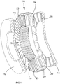
Figure 1 shows parts of an axial flux rotating electrical machine. Referring toFigure 1 , the machine comprises astator 10 sandwiched between tworotor discs stator 10 consists of two slottedlaminated toroids jacket 22 sandwiched between the two. The twostator toroids Stator windings 24 are wound in the slots in the finished stator. - The
rotor discs permanent magnets 16 with alternate north and south poles directed axially toward the stator. The rotor does not carry alternating flux and it can be constructed conveniently from cast iron. Thepermanent magnets 16 are preferably sintered Neodymium-Iron-Boron, providing a high magnetic loading, leading to a compact machine design. - The
axial machine 10 may be operated either as a generator or as a motor, or both. - Referring to
Figure 1 , it can be seen that thestator 10 is at the centre of the machine, and therefore is likely to experience the highest temperatures. In the arrangement ofFigure 1 , a coolingjacket 22 is provided in order to cool the stator. - In the arrangement of
Figure 1 , thestator 10 is formed from twoparts jacket 22 sandwiched between the two. The cooling jacket is disc-shaped, and is hollow to allow a cooling fluid to be circulated through it. Inlet and outlet pipes (not shown inFigure 1 ) are provided to allow the cooling fluid to enter and exit the cooling jacket. Any type of cooling fluid may be used, such as engine coolant. The coolingjacket 22 is manufactured from a strong, non-magnetic, heat-conducting material such as aluminium. In one embodiment the cooling jacket is formed from two discs of aluminium which are welded together. - The cooling
jacket 22 cools the machine at what is otherwise likely to be the hottest part, namely the centre of the machine. As a consequence it may be possible to rely on the cooling jacket to cool the whole machine. In this case, the machine may be manufactured as a totally enclosed unit. - Conventional rotating electrical machines suffer from the problem that contaminants such as sand and salt may enter the machine, reducing the machine's durability. With permanent magnet machines, the problem of contamination is even more serious, because contaminants can react with the magnets, causing them to rust and deteriorate. A totally enclosed unit has the advantage of being less susceptible to contamination, which may increase the machine's durability. A totally enclosed machine may also be packaged more effectively, as no allowance need be made for air cooling. Furthermore, a totally enclosed unit may be safer, as total containment of rotating components is possible. In addition, a totally enclosed unit may emit less electromagnetic interference, saving the expense of EMI screening.
-
Figures 2A to 2C show parts of thestator 10 and coolingjacket 22 in more detail.Figure 2A shows thestator 10 withwindings 24 in place.Overhang windings 42 are located around the circumference of the stator. Aninlet pipe 44 andoutlet pipe 46 take coolant into and out of the cooling jacket in the centre of the stator. -
Figure 2B shows a cross sectional view of the stator. The stator is formed of two slotted ring-shapeddiscs jacket 22 sandwiched between the two.Figure 2C shows the contact surface of the coolingjacket 22 with the stator in more detail. It can be seen that there is only minimal contact between theoverhang windings 42 and the coolingjacket 22. This may mean that the overhang windings may not be cooled effectively, which may reduce the efficiency of the machine. - An embodiment of the cooling jacket is shown in
Figures 3A-3E . The cooling jacket ofFigures 3A-3E is designed to be more effective in cooling the machine. -
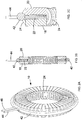
Figure 3A shows an exploded view of the cooling jacket. Referring toFigure 3A , the cooling jacket is formed from twosections sections rings sections - The
first section 48 of the cooling jacket carries a plurality ofheat sink fins 56 around its circumference. Thefins 56 are in the form of axially-running semi-cylinders on a ring around the outside surface of the first section. The space between the fins is designed to accommodate the stator windings. The outside surface of the cooling jacket between the fins is curved to fit with the curvature of the windings. Every sixth fin is longer than the others in the axial direction, and has a hole at each end. - The
second section 50 of the cooling jacket has similar, but smaller,fins 58 around its inside edge. Thefins 58 are in the form of axially-running semi-cylinders around the inside surface of the first section. The spaces between thefins 58 are designed to accommodate the inside of the stator windings, and the inside surface between the fins is curved to fit with the curvature of the windings. Some of thefins 58 are extended, and have bolt holes through the extended portions. - Thus, the assembled cooling jacket has an essentially annular shape, with axially running fins on both the inside and outside surfaces, and curved surfaces between the fins.
-
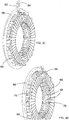
Figure 3B shows a cross sectional view of part of the assembled cooling jacket in place inside the stator. The cross section ofFigure 3B is taken through the extended fins. The twosections stator sections -
Figure 3C shows the stator withwindings 65 andoverhang windings 66 in place. The windings sit on the curved surfaces between the fins on both the inside and outside of the cooling jacket. The windings help to hold the stator and cooling jacket together. Aninlet pipe 63 andoutlet pipe 64 take coolant into and out of the cooling jacket. -
Figure 3D shows a more detailed view of the stator assembly. It can be seen that thewindings 65 slot into the grooves between thefins 56, while theoverhang windings 66 lie on top of thefins 56. Thus thefins 56 have a relatively large contact area with thewindings fins 56 act as a heat sink feature, and conduct heat away from the windings towards the coolant in the cooling jacket. Theinside windings 68 slot into the grooves between theinside fins 58, and thus the inside fins conduct heat away from the inside windings. - In order to prevent rotation of the stator, roll pins 70 are inserted through the holes in the longer fins into the stator.
Figure 3E shows a cross sectional view of the stator with the roll pins 70 in place. - The modified cooling jacket shown in
Figures 3A-3E may provide better cooling due to the extension of the inner and outer diameter of the cooling jacket. The cooling jacket has a larger contact area with the windings, which increases cooling efficiency. The production method may be cheaper, since most of the features can be cast which avoids the expense of machining. Furthermore, the two sections of the cooling jacket can be joined together without the need for welding. The cooling jacket is preferably made from a strong, non-magnetic, heat conducting material such as aluminium. - The axial flux machine described above may be connected to an engine in order to be driven as a generator. In this case, the cooling jacket may be connected to the engine's cooling system, so that the engine's coolant is also passed through the cooling jacket. This can remove the need to provide a separate cooling system (pump, radiator etc.) for the cooling jacket.
-
Figure 5 shows another embodiment, in which the inlet and outlet pipes are integrated with the heatsink and the machine housing. Referring toFigure 5 , thestator 186 is shown in place inside themachine housing 188. Aninlet pipe 190 is provided inside the machine for taking coolant into the stator cooling jacket. A similar outlet pipe is also provided for taking coolant out of the stator cooling jacket. This arrangement can allow the total number of components to be reduced, and assembly of the machine to be simplified. -
Figure 6 shows another embodiment with integrated inlet and outlet pipes. Referring toFigure 6 , acoolant path 192 is provided as part of the heatsink and machine housing, which can facilitate the supply of coolant from outside of the machine to and from the cooling jacket. - Referring back to the schematic diagram of an axial flux machine in
Figure 1 , it can be seen that some arrangement is need to hold thestator 10 in place.Figures 4A-4D show parts of a stator retention assembly. -
Figure 4A shows a retaining ring which may be used to retain a stator assembly. The retaining ring has a plurality ofteeth 74 extending radially inwards on one edge. -
Figure 4B shows an exploded view of the stator assembly and the retaining ring. The stator assembly is formed from a cooling jacket sandwiched between two stator sections, as discussed above with reference toFigures 3A-3E . As can be seen fromFigure 4B , some of the fins on the outside part of the cooling jacket extend outwards in a radial direction next to the overhang windings. Theteeth 74 of the retainingring 72 are designed to engage with theextended fins 76. -
Figure 4C is a cross sectional view of the stator assembly in place on the retaining ring. As can be seen fromFigure 4C , holes in the retainingring teeth 74 are aligned with holes in theextended fins 76. This allows the stator assembly to be bolted to the retaining ring. An end view of the assembled stator and retaining ring is shown inFigure 4D . - In the stator retention assembly shown in
Figures 4A-4D , the stator assembly is held in place by bolting the cooling jacket to the retention ring, rather than clamping the stator. This means that the retaining ring is not in the main magnetic field, which reduces eddy current losses. Furthermore, by bolting the stator assembly rather than clamping it, the risk of stator rotation under short circuit conditions is reduced. Roll pins are inserted between the cooling jacket and stator as shown inFigure 3E , to further reduce the risk of stator rotation. Since the retention ring is not in direct contact with the stator, the risk of damaging the stator end windings is reduced. Furthermore, the retention assembly shown inFigures 4A-4D is easier to assemble than the previously considered techniques, and uses fewer components. -
Figure 7 shows another embodiment in which the stator retention ring is integrated with the machine housing. In this embodiment, thestator assembly 194 is retained by bolting the cooling jacket directly tomountings 196 in themachine housing 198. This reduces the number of parts and facilitates manufacture of the machine.
Claims (13)
- An axial flux rotating electrical machine comprising:a stator (10);a cooling jacket (22) inside the stator for cooling the stator; andstator windings (24) around the stator and the cooling jacket;characterised in that:the cooling jacket (22) comprises a plurality of fins (56, 76) which extend beyond the circumference of the stator, wherein the fins define slots which accommodate the stator windings and the fins act as heat sinks for the stator windings;some of the fins (76) extend outwards in a radial direction by a greater amount than the other fins (56); andthe extended fins (76) are used for securing the stator (10) to the machine.
- An axial flux machine according to claim 1, wherein at least some of the fins (56, 76) define open slots which accommodate stator windings.
- An axial flux machine according to claim 1 or 2, wherein the fins (56) extend radially outwards such that, when the stator is wound, overhang windings (66) rest on the fins.
- An axial flux machine according to any of the preceding claims, wherein the fins (56) are in the form of axially-running semi-cylinders.
- An axial flux machine according to any of the preceding claims, wherein the stator (10) comprises open slots for accommodating the stator windings.
- An axial flux machine according to any of the preceding claims, further comprising roll pins (70) inserted between the cooling jacket and the stator.
- An axial flux machine according to any of the preceding claims, further comprising a retention ring (72), wherein the cooling jacket (22) is secured to the retention ring (72).
- An axial flux machine according to claim 7, wherein the retention ring (72) comprises a plurality of teeth (74) aligned with the extended fins (76) on the cooling jacket.
- An axial flux machine according to any of the preceding claims, further comprising a machine housing, wherein the stator is enclosed within and/or secured to the machine housing.
- An axial flux machine according to claim 9 when dependent on claim 7 or 8, wherein the retention ring (72) is integrated with the machine housing.
- An axial flux machine according to claim 10, further comprising an inlet pipe (44) and an outlet pipe (46) for supplying coolant to and from the cooling jacket, wherein the inlet pipe and outlet pipe are integrated with the machine housing.
- A method of assembling an axial flux rotating electrical machine, the method comprising:providing a stator assembly (10) comprising two stator parts (18, 20);providing a cooling jacket (22);placing the cooling jacket (22) between the two stator parts (18, 20);winding stator windings (24) around the stator and cooling jacket; andsecuring the stator assembly (10) to the machine;characterised in that:the cooling jacket (22) comprises a plurality of fins (56, 76) which extend beyond the circumference of the stator, wherein the fins define slots which accommodate the stator windings and the fins act as heat sinks for the stator windings;some of the fins (76) extend outwards in a radial direction by a greater amount than the other fins (56); andthe extended fins (76) are used for securing the stator (10) to the machine.
- A method according to claim 12, wherein the step of winding the stator windings (24) comprises winding stator windings (65) into open slots between the fins.
Applications Claiming Priority (3)
| Application Number | Priority Date | Filing Date | Title |
|---|---|---|---|
| GBGB0813032.0A GB0813032D0 (en) | 2008-07-16 | 2008-07-16 | Axial flux machine |
| GBGB0907982.3A GB0907982D0 (en) | 2008-07-16 | 2009-05-08 | Axial flux machine |
| EP09784734.7A EP2304862B1 (en) | 2008-07-16 | 2009-07-14 | Axial flux machine |
Related Parent Applications (3)
| Application Number | Title | Priority Date | Filing Date |
|---|---|---|---|
| EP09784734.7A Division-Into EP2304862B1 (en) | 2008-07-16 | 2009-07-14 | Axial flux machine |
| EP09784734.7A Division EP2304862B1 (en) | 2008-07-16 | 2009-07-14 | Axial flux machine |
| EP09784734.7 Division | 2009-07-14 |
Publications (3)
| Publication Number | Publication Date |
|---|---|
| EP2632027A2 EP2632027A2 (en) | 2013-08-28 |
| EP2632027A3 EP2632027A3 (en) | 2014-02-26 |
| EP2632027B1 true EP2632027B1 (en) | 2017-12-27 |
Family
ID=39722392
Family Applications (3)
| Application Number | Title | Priority Date | Filing Date |
|---|---|---|---|
| EP09784734.7A Active EP2304862B1 (en) | 2008-07-16 | 2009-07-14 | Axial flux machine |
| EP13169149.5A Active EP2632027B1 (en) | 2008-07-16 | 2009-07-14 | Axial flux machine |
| EP13169144.6A Active EP2632026B1 (en) | 2008-07-16 | 2009-07-14 | Cooling jacket for axial flux machine |
Family Applications Before (1)
| Application Number | Title | Priority Date | Filing Date |
|---|---|---|---|
| EP09784734.7A Active EP2304862B1 (en) | 2008-07-16 | 2009-07-14 | Axial flux machine |
Family Applications After (1)
| Application Number | Title | Priority Date | Filing Date |
|---|---|---|---|
| EP13169144.6A Active EP2632026B1 (en) | 2008-07-16 | 2009-07-14 | Cooling jacket for axial flux machine |
Country Status (5)
| Country | Link |
|---|---|
| US (1) | US20110241460A1 (en) |
| EP (3) | EP2304862B1 (en) |
| CN (1) | CN102160257A (en) |
| GB (2) | GB0813032D0 (en) |
| WO (1) | WO2010007385A2 (en) |
Cited By (1)
| Publication number | Priority date | Publication date | Assignee | Title |
|---|---|---|---|---|
| DE102020106775A1 (en) | 2020-03-12 | 2021-09-16 | Schaeffler Technologies AG & Co. KG | Stator for an axial flux machine, method for manufacturing a stator and axial flux machine |
Families Citing this family (50)
| Publication number | Priority date | Publication date | Assignee | Title |
|---|---|---|---|---|
| JP5875746B2 (en) * | 2009-09-09 | 2016-03-02 | 株式会社三井ハイテック | Manufacturing method of stator core |
| US8896175B2 (en) | 2010-03-30 | 2014-11-25 | Volvo Technology Corporation | Rotor of an electric machine with embedded permanent magnets and electric machine |
| CN102088800B (en) * | 2011-01-14 | 2013-01-30 | 唐少章 | Magnetic heating machine |
| CN102186270B (en) * | 2011-01-14 | 2012-12-26 | 唐少章 | Magnetic heating machine |
| US20120212085A1 (en) * | 2011-02-17 | 2012-08-23 | The Hong Kong Polytechnic University | Axial-flux electric machine |
| JP5743988B2 (en) * | 2012-09-18 | 2015-07-01 | 株式会社東芝 | Transverse magnetic flux type motor |
| US10447102B2 (en) * | 2013-03-15 | 2019-10-15 | Regal Beloit Australia Pty. Ltd. | Permanent magnet electrical machines and methods of assembling the same |
| KR101492172B1 (en) * | 2013-03-20 | 2015-02-11 | 전자부품연구원 | Radial and Axial Flux Motor using Integrated Windings |
| KR101440431B1 (en) * | 2013-03-28 | 2014-09-17 | 현대모비스(주) | axial flux permanent magnet motor |
| JP6255231B2 (en) * | 2013-12-11 | 2017-12-27 | 株式会社ダイナックス | Axial gap motor |
| AU2015239088B2 (en) | 2014-04-02 | 2018-11-22 | J.H. Beheer B.V. | Stator portion for an electric machine comprising an permanent magnet rotor |
| JP6270213B2 (en) * | 2014-06-05 | 2018-01-31 | 株式会社神戸製鋼所 | Electric motor |
| DE102014220201A1 (en) * | 2014-10-06 | 2016-04-07 | Bühler Motor GmbH | Electronically commutated DC motor, in particular for an oil pump |
| US10548467B2 (en) | 2015-06-02 | 2020-02-04 | GI Scientific, LLC | Conductive optical element |
| CN108289595B (en) | 2015-07-21 | 2021-03-16 | 图像科学有限责任公司 | Endoscopic accessory with angularly adjustable exit port |
| EP3340436A4 (en) * | 2015-08-18 | 2019-04-03 | Kabushiki Kaisha Kobe Seiko Sho (Kobe Steel, Ltd.) | Axial gap type dynamo-electric machine |
| US11527933B2 (en) | 2015-10-02 | 2022-12-13 | E-Circuit Motors, Inc. | Stator and rotor design for periodic torque requirements |
| US11121614B2 (en) | 2017-06-05 | 2021-09-14 | E-Circuit Motors, Inc. | Pre-warped rotors for control of magnet-stator gap in axial flux machines |
| FR3048827B1 (en) * | 2016-03-14 | 2023-06-02 | Whylot | ROTOR FOR AXIAL FLOW ELECTROMAGNETIC MOTOR OR GENERATOR WITH SEMI-BURIED MAGNET WITH AXIAL HOLDING MEANS |
| US10086538B2 (en) | 2016-03-17 | 2018-10-02 | Ford Global Technologies, Llc | Thermal management assembly for an electrified vehicle |
| US10038351B2 (en) | 2016-03-17 | 2018-07-31 | Ford Global Technologies, Llc | Thermal management assembly for an electrified vehicle |
| JP2019511900A (en) * | 2016-04-13 | 2019-04-25 | ジェネシス ロボティクス アンド モーション テクノロジーズ カナダ アンリミテッド ライアビリティ カンパニー | Electromechanical device with axial thrust bearing |
| CN105720712B (en) * | 2016-04-19 | 2018-02-02 | 北京康城科技有限公司 | The disc type wheel hub electric motor that a kind of stator liquid is cold and rotor magnetic steel is built-in |
| CN105896766A (en) * | 2016-04-19 | 2016-08-24 | 北京康城科技有限公司 | Stator liquid cooling structure for built-in disc type motor |
| US10826344B2 (en) * | 2016-11-17 | 2020-11-03 | General Electric Company | High speed electric machine with embedded rotor magnets |
| CN106374705B (en) * | 2016-12-05 | 2020-04-24 | 哈尔滨工业大学 | Axial flux permanent magnet machine |
| DE102016225520A1 (en) * | 2016-12-20 | 2018-06-21 | Bayerische Motoren Werke Aktiengesellschaft | Electrical machine, in particular for a motor vehicle, and motor vehicle with such an electric machine |
| CN106505816B (en) * | 2016-12-26 | 2023-05-12 | 重庆市渝展电气有限公司 | Disk type permanent magnet generator |
| CN106787437A (en) * | 2017-01-17 | 2017-05-31 | 侯神保 | A kind of electric generator for electric vehicle |
| US11005322B2 (en) | 2017-06-05 | 2021-05-11 | E-Circuit Motors, Inc. | Rotor assemblies for axial flux machines |
| US11831211B2 (en) | 2017-06-05 | 2023-11-28 | E-Circuit Motors, Inc. | Stator and rotor design for periodic torque requirements |
| LU100555B1 (en) * | 2017-12-13 | 2019-06-28 | Luxembourg Inst Science & Tech List | Compact halbach electrical generator with coils arranged circumferentially |
| EP3687048B1 (en) | 2019-01-22 | 2022-04-06 | Rolls-Royce Deutschland Ltd & Co KG | Hybrid rotor for an axial flux electrical machine |
| CN111525763B (en) * | 2019-02-02 | 2022-05-31 | 通用汽车环球科技运作有限责任公司 | Axial flux motor with insulated rotor |
| CN110212708B (en) * | 2019-05-07 | 2021-11-12 | 上海第一机床厂有限公司 | Assembly method of high-temperature gas cooled reactor vortex speed limiter |
| DE102020102824A1 (en) * | 2019-07-15 | 2021-01-21 | Gëzim Krasniqi | Electric motor generator device and method for operating a technical system |
| US11025107B2 (en) * | 2019-10-30 | 2021-06-01 | Maxxwell Motors, Inc. | Fan impeller to cool an axial flux rotating machine, and applications thereof |
| KR20220100001A (en) * | 2019-11-12 | 2022-07-14 | 이-서킷 모터스 인코퍼레이티드 | Improved rotor assembly for axial flux machines |
| FR3110767A1 (en) * | 2020-05-19 | 2021-11-26 | Whylot | Magnet pole with several individual magnets of variable section |
| TWI719907B (en) * | 2020-06-05 | 2021-02-21 | 東元電機股份有限公司 | Method of manufacturing closed-type and liquid cooling motor frame and closed-type and liquid cooling motor frame thereof |
| KR20220031823A (en) * | 2020-09-04 | 2022-03-14 | 현대자동차주식회사 | Rotor of axial flux motor |
| CN112491197B (en) * | 2020-11-20 | 2022-04-08 | 安徽大学 | Oil-cooled axial flux motor with built-in axial flow fan |
| JP2024506380A (en) | 2021-02-17 | 2024-02-13 | イー-サーキット モーターズ, インコーポレイテッド | Planar stator configuration for axial flux machines |
| US11424666B1 (en) | 2021-03-18 | 2022-08-23 | Maxxwell Motors, Inc. | Manufactured coil for an electrical machine |
| DE202022101430U1 (en) * | 2021-04-13 | 2022-04-14 | Konstantin Dominik Appelt | Device for lighting and disinfecting rooms |
| US11646611B2 (en) * | 2021-07-28 | 2023-05-09 | GM Global Technology Operations LLC | Locking mechanism for segmented stator core |
| AU2022318884A1 (en) | 2021-07-30 | 2024-01-25 | E-Circuit Motors, Inc. | Magnetic material filled printed circuit boards and printed circuit board stators |
| US11689073B2 (en) | 2021-08-13 | 2023-06-27 | GM Global Technology Operations LLC | Rotor core design |
| US11336130B1 (en) | 2021-08-17 | 2022-05-17 | E-Circuit Motors, Inc. | Low-loss planar winding configurations for an axial flux machine |
| US11942829B2 (en) | 2022-07-26 | 2024-03-26 | Borgwarner Inc. | Bonded rotor plate |
Family Cites Families (17)
| Publication number | Priority date | Publication date | Assignee | Title |
|---|---|---|---|---|
| JPH0545098Y2 (en) * | 1989-08-25 | 1993-11-17 | ||
| US5334899A (en) * | 1991-09-30 | 1994-08-02 | Dymytro Skybyk | Polyphase brushless DC and AC synchronous machines |
| DE19854465C1 (en) * | 1998-11-25 | 2000-03-09 | Daimler Chrysler Ag | Liquid cooled motor vehicle alternator or dynamo in a casing has a gap between its casing and alternator for the in- and outflow of cooling liquid. |
| GB0100635D0 (en) * | 2001-01-10 | 2001-02-21 | Newage Int Ltd | Apparatus for and method of locating magnets |
| US6849982B2 (en) * | 2001-05-02 | 2005-02-01 | Newage International Limited | Toroidal electrical machine and an annular winding carrier therefor |
| WO2003003546A1 (en) * | 2001-06-28 | 2003-01-09 | Newage International Limited | A permanent magnet electrical machine |
| JP4249014B2 (en) * | 2001-07-31 | 2009-04-02 | ヤマハ発動機株式会社 | Rotating electric machine |
| US6664689B2 (en) * | 2001-08-06 | 2003-12-16 | Mitchell Rose | Ring-shaped motor core with toroidally-wound coils |
| EP1304790A1 (en) * | 2001-10-18 | 2003-04-23 | "VLAAMSE INSTELLING VOOR TECHNOLOGISCH ONDERZOEK", afgekort "V.I.T.O." | An axial flux permanent magnet generator/motor |
| JP2004312886A (en) * | 2003-04-08 | 2004-11-04 | Suzuki Motor Corp | Cooling structure of electric motor |
| GB0320559D0 (en) * | 2003-09-02 | 2003-10-01 | Newage Int Ltd | An alternator assembly |
| JP2006087216A (en) * | 2004-09-16 | 2006-03-30 | Nissan Motor Co Ltd | Rotor structure of rotating electric machine |
| JP2006174553A (en) * | 2004-12-14 | 2006-06-29 | Nissan Motor Co Ltd | Rotor structure for axial gap type dynamo-electric machine |
| WO2006077812A1 (en) * | 2005-01-19 | 2006-07-27 | Daikin Industries, Ltd. | Rotor, axial gap type motor, motor driving method, and compressor |
| JP2006271161A (en) * | 2005-03-25 | 2006-10-05 | Daikin Ind Ltd | Core, armature, motor, and compressor |
| DE102005052783A1 (en) * | 2005-11-05 | 2007-05-10 | Volkswagen Ag | Electrical machine`s e.g. electrical drive, stator manufacturing method for motor vehicle, involves forming stator from stator carrier and stator outer part, where stator carrier is formed from stator carrier inner and outer parts |
| JP2008109817A (en) * | 2006-10-27 | 2008-05-08 | Nissan Motor Co Ltd | Motor having concentrated windings |
-
2008
- 2008-07-16 GB GBGB0813032.0A patent/GB0813032D0/en not_active Ceased
-
2009
- 2009-05-08 GB GBGB0907982.3A patent/GB0907982D0/en not_active Ceased
- 2009-07-14 EP EP09784734.7A patent/EP2304862B1/en active Active
- 2009-07-14 WO PCT/GB2009/001781 patent/WO2010007385A2/en active Application Filing
- 2009-07-14 US US13/054,350 patent/US20110241460A1/en not_active Abandoned
- 2009-07-14 EP EP13169149.5A patent/EP2632027B1/en active Active
- 2009-07-14 EP EP13169144.6A patent/EP2632026B1/en active Active
- 2009-07-14 CN CN2009801359269A patent/CN102160257A/en active Pending
Non-Patent Citations (1)
| Title |
|---|
| None * |
Cited By (2)
| Publication number | Priority date | Publication date | Assignee | Title |
|---|---|---|---|---|
| DE102020106775A1 (en) | 2020-03-12 | 2021-09-16 | Schaeffler Technologies AG & Co. KG | Stator for an axial flux machine, method for manufacturing a stator and axial flux machine |
| WO2021180267A1 (en) | 2020-03-12 | 2021-09-16 | Schaeffler Technologies AG & Co. KG | Stator for an axial flux machine, method for producing a stator and axial flux machine |
Also Published As
| Publication number | Publication date |
|---|---|
| EP2304862B1 (en) | 2015-12-16 |
| US20110241460A1 (en) | 2011-10-06 |
| EP2632026A3 (en) | 2014-02-26 |
| GB0813032D0 (en) | 2008-08-20 |
| WO2010007385A3 (en) | 2010-04-29 |
| EP2632026B1 (en) | 2018-01-10 |
| EP2632026A2 (en) | 2013-08-28 |
| EP2632027A3 (en) | 2014-02-26 |
| GB0907982D0 (en) | 2009-06-24 |
| EP2304862A2 (en) | 2011-04-06 |
| CN102160257A (en) | 2011-08-17 |
| EP2632027A2 (en) | 2013-08-28 |
| WO2010007385A2 (en) | 2010-01-21 |
Similar Documents
| Publication | Publication Date | Title |
|---|---|---|
| EP2632027B1 (en) | Axial flux machine | |
| EP3485558B1 (en) | Stator for an axial flux machine and method for producing the same | |
| JP3944140B2 (en) | Claw pole motor stator | |
| EP3022830B1 (en) | A stator for an electric motor | |
| US9112386B2 (en) | Electric motor with improved flux path and power density | |
| CN102208837B (en) | Rotating machine | |
| EP2897259B1 (en) | Rotating electric machine | |
| WO2005078899A1 (en) | Compact dynamoelectric machine | |
| CA2846422A1 (en) | Cooling arrangement for an electric motor | |
| JP6402739B2 (en) | Rotating electric machine | |
| US20130076170A1 (en) | Stator for electric machine | |
| WO2023113993A1 (en) | Fluid cooled stator | |
| CN111384831B (en) | Method for manufacturing rotor | |
| CN111247724A (en) | Electric machine with cooling device comprising partially subdivided channels | |
| JPH10225034A (en) | Rotor for dynamo-electric machine | |
| JP2013192339A (en) | Induction motor | |
| JP5652305B2 (en) | Stator for rotating electrical machine | |
| JP2007074853A (en) | Stator structure of rotating electric machine | |
| US20220360124A1 (en) | Stator Cooling Arrangement | |
| JP6116365B2 (en) | Liquid cooling motor | |
| JP2019161861A (en) | Rotary electric machine | |
| US20220399766A1 (en) | Stator cooling assembly for electric machine | |
| JP2010226815A (en) | Motor stator, split stator, and manufacturing method for the same | |
| JP2024013921A (en) | rotating electric machine | |
| JPH1023705A (en) | Induction motor |
Legal Events
| Date | Code | Title | Description |
|---|---|---|---|
| PUAI | Public reference made under article 153(3) epc to a published international application that has entered the european phase |
Free format text: ORIGINAL CODE: 0009012 |
|
| AC | Divisional application: reference to earlier application |
Ref document number: 2304862 Country of ref document: EP Kind code of ref document: P |
|
| AK | Designated contracting states |
Kind code of ref document: A2 Designated state(s): AT BE BG CH CY CZ DE DK EE ES FI FR GB GR HR HU IE IS IT LI LT LU LV MC MK MT NL NO PL PT RO SE SI SK SM TR |
|
| PUAL | Search report despatched |
Free format text: ORIGINAL CODE: 0009013 |
|
| AK | Designated contracting states |
Kind code of ref document: A3 Designated state(s): AT BE BG CH CY CZ DE DK EE ES FI FR GB GR HR HU IE IS IT LI LT LU LV MC MK MT NL NO PL PT RO SE SI SK SM TR |
|
| RIC1 | Information provided on ipc code assigned before grant |
Ipc: H02K 1/27 20060101AFI20140122BHEP Ipc: H02K 9/19 20060101ALI20140122BHEP Ipc: H02K 21/24 20060101ALI20140122BHEP |
|
| 17P | Request for examination filed |
Effective date: 20140822 |
|
| RBV | Designated contracting states (corrected) |
Designated state(s): AT BE BG CH CY CZ DE DK EE ES FI FR GB GR HR HU IE IS IT LI LT LU LV MC MK MT NL NO PL PT RO SE SI SK SM TR |
|
| 17Q | First examination report despatched |
Effective date: 20150206 |
|
| GRAP | Despatch of communication of intention to grant a patent |
Free format text: ORIGINAL CODE: EPIDOSNIGR1 |
|
| INTG | Intention to grant announced |
Effective date: 20170710 |
|
| RIN1 | Information on inventor provided before grant (corrected) |
Inventor name: GURPREET, SAINI Inventor name: RICHARD, GRAY Inventor name: ADRIAN, BELL Inventor name: SHANEL, MARTIN Inventor name: THIAGARAJAN, GOPINATH, THELUNGUPALAYAM Inventor name: NEIL, BROWN Inventor name: ABDELSLAM, MEBARKI |
|
| GRAS | Grant fee paid |
Free format text: ORIGINAL CODE: EPIDOSNIGR3 |
|
| GRAA | (expected) grant |
Free format text: ORIGINAL CODE: 0009210 |
|
| AC | Divisional application: reference to earlier application |
Ref document number: 2304862 Country of ref document: EP Kind code of ref document: P |
|
| AK | Designated contracting states |
Kind code of ref document: B1 Designated state(s): AT BE BG CH CY CZ DE DK EE ES FI FR GB GR HR HU IE IS IT LI LT LU LV MC MK MT NL NO PL PT RO SE SI SK SM TR |
|
| REG | Reference to a national code |
Ref country code: GB Ref legal event code: FG4D |
|
| REG | Reference to a national code |
Ref country code: CH Ref legal event code: EP |
|
| REG | Reference to a national code |
Ref country code: AT Ref legal event code: REF Ref document number: 959086 Country of ref document: AT Kind code of ref document: T Effective date: 20180115 |
|
| REG | Reference to a national code |
Ref country code: IE Ref legal event code: FG4D |
|
| REG | Reference to a national code |
Ref country code: DE Ref legal event code: R096 Ref document number: 602009050171 Country of ref document: DE |
|
| PG25 | Lapsed in a contracting state [announced via postgrant information from national office to epo] |
Ref country code: LT Free format text: LAPSE BECAUSE OF FAILURE TO SUBMIT A TRANSLATION OF THE DESCRIPTION OR TO PAY THE FEE WITHIN THE PRESCRIBED TIME-LIMIT Effective date: 20171227 Ref country code: NO Free format text: LAPSE BECAUSE OF FAILURE TO SUBMIT A TRANSLATION OF THE DESCRIPTION OR TO PAY THE FEE WITHIN THE PRESCRIBED TIME-LIMIT Effective date: 20180327 Ref country code: FI Free format text: LAPSE BECAUSE OF FAILURE TO SUBMIT A TRANSLATION OF THE DESCRIPTION OR TO PAY THE FEE WITHIN THE PRESCRIBED TIME-LIMIT Effective date: 20171227 |
|
| REG | Reference to a national code |
Ref country code: NL Ref legal event code: MP Effective date: 20171227 |
|
| REG | Reference to a national code |
Ref country code: LT Ref legal event code: MG4D |
|
| REG | Reference to a national code |
Ref country code: AT Ref legal event code: MK05 Ref document number: 959086 Country of ref document: AT Kind code of ref document: T Effective date: 20171227 |
|
| PG25 | Lapsed in a contracting state [announced via postgrant information from national office to epo] |
Ref country code: LV Free format text: LAPSE BECAUSE OF FAILURE TO SUBMIT A TRANSLATION OF THE DESCRIPTION OR TO PAY THE FEE WITHIN THE PRESCRIBED TIME-LIMIT Effective date: 20171227 Ref country code: GR Free format text: LAPSE BECAUSE OF FAILURE TO SUBMIT A TRANSLATION OF THE DESCRIPTION OR TO PAY THE FEE WITHIN THE PRESCRIBED TIME-LIMIT Effective date: 20180328 Ref country code: HR Free format text: LAPSE BECAUSE OF FAILURE TO SUBMIT A TRANSLATION OF THE DESCRIPTION OR TO PAY THE FEE WITHIN THE PRESCRIBED TIME-LIMIT Effective date: 20171227 Ref country code: BG Free format text: LAPSE BECAUSE OF FAILURE TO SUBMIT A TRANSLATION OF THE DESCRIPTION OR TO PAY THE FEE WITHIN THE PRESCRIBED TIME-LIMIT Effective date: 20180327 |
|
| PG25 | Lapsed in a contracting state [announced via postgrant information from national office to epo] |
Ref country code: NL Free format text: LAPSE BECAUSE OF FAILURE TO SUBMIT A TRANSLATION OF THE DESCRIPTION OR TO PAY THE FEE WITHIN THE PRESCRIBED TIME-LIMIT Effective date: 20171227 |
|
| PG25 | Lapsed in a contracting state [announced via postgrant information from national office to epo] |
Ref country code: SK Free format text: LAPSE BECAUSE OF FAILURE TO SUBMIT A TRANSLATION OF THE DESCRIPTION OR TO PAY THE FEE WITHIN THE PRESCRIBED TIME-LIMIT Effective date: 20171227 Ref country code: EE Free format text: LAPSE BECAUSE OF FAILURE TO SUBMIT A TRANSLATION OF THE DESCRIPTION OR TO PAY THE FEE WITHIN THE PRESCRIBED TIME-LIMIT Effective date: 20171227 Ref country code: CY Free format text: LAPSE BECAUSE OF FAILURE TO SUBMIT A TRANSLATION OF THE DESCRIPTION OR TO PAY THE FEE WITHIN THE PRESCRIBED TIME-LIMIT Effective date: 20171227 Ref country code: CZ Free format text: LAPSE BECAUSE OF FAILURE TO SUBMIT A TRANSLATION OF THE DESCRIPTION OR TO PAY THE FEE WITHIN THE PRESCRIBED TIME-LIMIT Effective date: 20171227 Ref country code: ES Free format text: LAPSE BECAUSE OF FAILURE TO SUBMIT A TRANSLATION OF THE DESCRIPTION OR TO PAY THE FEE WITHIN THE PRESCRIBED TIME-LIMIT Effective date: 20171227 |
|
| PG25 | Lapsed in a contracting state [announced via postgrant information from national office to epo] |
Ref country code: IT Free format text: LAPSE BECAUSE OF FAILURE TO SUBMIT A TRANSLATION OF THE DESCRIPTION OR TO PAY THE FEE WITHIN THE PRESCRIBED TIME-LIMIT Effective date: 20171227 Ref country code: PL Free format text: LAPSE BECAUSE OF FAILURE TO SUBMIT A TRANSLATION OF THE DESCRIPTION OR TO PAY THE FEE WITHIN THE PRESCRIBED TIME-LIMIT Effective date: 20171227 Ref country code: SM Free format text: LAPSE BECAUSE OF FAILURE TO SUBMIT A TRANSLATION OF THE DESCRIPTION OR TO PAY THE FEE WITHIN THE PRESCRIBED TIME-LIMIT Effective date: 20171227 Ref country code: AT Free format text: LAPSE BECAUSE OF FAILURE TO SUBMIT A TRANSLATION OF THE DESCRIPTION OR TO PAY THE FEE WITHIN THE PRESCRIBED TIME-LIMIT Effective date: 20171227 Ref country code: IS Free format text: LAPSE BECAUSE OF FAILURE TO SUBMIT A TRANSLATION OF THE DESCRIPTION OR TO PAY THE FEE WITHIN THE PRESCRIBED TIME-LIMIT Effective date: 20180427 Ref country code: RO Free format text: LAPSE BECAUSE OF FAILURE TO SUBMIT A TRANSLATION OF THE DESCRIPTION OR TO PAY THE FEE WITHIN THE PRESCRIBED TIME-LIMIT Effective date: 20171227 |
|
| REG | Reference to a national code |
Ref country code: DE Ref legal event code: R097 Ref document number: 602009050171 Country of ref document: DE |
|
| PLBE | No opposition filed within time limit |
Free format text: ORIGINAL CODE: 0009261 |
|
| STAA | Information on the status of an ep patent application or granted ep patent |
Free format text: STATUS: NO OPPOSITION FILED WITHIN TIME LIMIT |
|
| PG25 | Lapsed in a contracting state [announced via postgrant information from national office to epo] |
Ref country code: DK Free format text: LAPSE BECAUSE OF FAILURE TO SUBMIT A TRANSLATION OF THE DESCRIPTION OR TO PAY THE FEE WITHIN THE PRESCRIBED TIME-LIMIT Effective date: 20171227 |
|
| 26N | No opposition filed |
Effective date: 20180928 |
|
| REG | Reference to a national code |
Ref country code: DE Ref legal event code: R119 Ref document number: 602009050171 Country of ref document: DE |
|
| PG25 | Lapsed in a contracting state [announced via postgrant information from national office to epo] |
Ref country code: SI Free format text: LAPSE BECAUSE OF FAILURE TO SUBMIT A TRANSLATION OF THE DESCRIPTION OR TO PAY THE FEE WITHIN THE PRESCRIBED TIME-LIMIT Effective date: 20171227 |
|
| REG | Reference to a national code |
Ref country code: CH Ref legal event code: PL |
|
| PG25 | Lapsed in a contracting state [announced via postgrant information from national office to epo] |
Ref country code: MC Free format text: LAPSE BECAUSE OF FAILURE TO SUBMIT A TRANSLATION OF THE DESCRIPTION OR TO PAY THE FEE WITHIN THE PRESCRIBED TIME-LIMIT Effective date: 20171227 Ref country code: LU Free format text: LAPSE BECAUSE OF NON-PAYMENT OF DUE FEES Effective date: 20180714 |
|
| REG | Reference to a national code |
Ref country code: BE Ref legal event code: MM Effective date: 20180731 |
|
| REG | Reference to a national code |
Ref country code: IE Ref legal event code: MM4A |
|
| PG25 | Lapsed in a contracting state [announced via postgrant information from national office to epo] |
Ref country code: IE Free format text: LAPSE BECAUSE OF NON-PAYMENT OF DUE FEES Effective date: 20180714 Ref country code: CH Free format text: LAPSE BECAUSE OF NON-PAYMENT OF DUE FEES Effective date: 20180731 Ref country code: LI Free format text: LAPSE BECAUSE OF NON-PAYMENT OF DUE FEES Effective date: 20180731 Ref country code: FR Free format text: LAPSE BECAUSE OF NON-PAYMENT OF DUE FEES Effective date: 20180731 Ref country code: DE Free format text: LAPSE BECAUSE OF NON-PAYMENT OF DUE FEES Effective date: 20190201 |
|
| PG25 | Lapsed in a contracting state [announced via postgrant information from national office to epo] |
Ref country code: BE Free format text: LAPSE BECAUSE OF NON-PAYMENT OF DUE FEES Effective date: 20180731 |
|
| PG25 | Lapsed in a contracting state [announced via postgrant information from national office to epo] |
Ref country code: MT Free format text: LAPSE BECAUSE OF NON-PAYMENT OF DUE FEES Effective date: 20180714 |
|
| PG25 | Lapsed in a contracting state [announced via postgrant information from national office to epo] |
Ref country code: TR Free format text: LAPSE BECAUSE OF FAILURE TO SUBMIT A TRANSLATION OF THE DESCRIPTION OR TO PAY THE FEE WITHIN THE PRESCRIBED TIME-LIMIT Effective date: 20171227 |
|
| PG25 | Lapsed in a contracting state [announced via postgrant information from national office to epo] |
Ref country code: HU Free format text: LAPSE BECAUSE OF FAILURE TO SUBMIT A TRANSLATION OF THE DESCRIPTION OR TO PAY THE FEE WITHIN THE PRESCRIBED TIME-LIMIT; INVALID AB INITIO Effective date: 20090714 Ref country code: PT Free format text: LAPSE BECAUSE OF FAILURE TO SUBMIT A TRANSLATION OF THE DESCRIPTION OR TO PAY THE FEE WITHIN THE PRESCRIBED TIME-LIMIT Effective date: 20171227 |
|
| PG25 | Lapsed in a contracting state [announced via postgrant information from national office to epo] |
Ref country code: MK Free format text: LAPSE BECAUSE OF NON-PAYMENT OF DUE FEES Effective date: 20171227 Ref country code: SE Free format text: LAPSE BECAUSE OF FAILURE TO SUBMIT A TRANSLATION OF THE DESCRIPTION OR TO PAY THE FEE WITHIN THE PRESCRIBED TIME-LIMIT Effective date: 20171227 |
|
| P01 | Opt-out of the competence of the unified patent court (upc) registered |
Effective date: 20230510 |
|
| PGFP | Annual fee paid to national office [announced via postgrant information from national office to epo] |
Ref country code: GB Payment date: 20230727 Year of fee payment: 15 |