EP2632018A1 - Universal serial bus charging device - Google Patents
Universal serial bus charging device Download PDFInfo
- Publication number
- EP2632018A1 EP2632018A1 EP12157106.1A EP12157106A EP2632018A1 EP 2632018 A1 EP2632018 A1 EP 2632018A1 EP 12157106 A EP12157106 A EP 12157106A EP 2632018 A1 EP2632018 A1 EP 2632018A1
- Authority
- EP
- European Patent Office
- Prior art keywords
- charger
- charging device
- transmission line
- usb
- connector
- Prior art date
- Legal status (The legal status is an assumption and is not a legal conclusion. Google has not performed a legal analysis and makes no representation as to the accuracy of the status listed.)
- Withdrawn
Links
Images


Classifications
-
- H—ELECTRICITY
- H01—ELECTRIC ELEMENTS
- H01R—ELECTRICALLY-CONDUCTIVE CONNECTIONS; STRUCTURAL ASSOCIATIONS OF A PLURALITY OF MUTUALLY-INSULATED ELECTRICAL CONNECTING ELEMENTS; COUPLING DEVICES; CURRENT COLLECTORS
- H01R31/00—Coupling parts supported only by co-operation with counterpart
- H01R31/06—Intermediate parts for linking two coupling parts, e.g. adapter
- H01R31/065—Intermediate parts for linking two coupling parts, e.g. adapter with built-in electric apparatus
-
- H—ELECTRICITY
- H01—ELECTRIC ELEMENTS
- H01M—PROCESSES OR MEANS, e.g. BATTERIES, FOR THE DIRECT CONVERSION OF CHEMICAL ENERGY INTO ELECTRICAL ENERGY
- H01M50/00—Constructional details or processes of manufacture of the non-active parts of electrochemical cells other than fuel cells, e.g. hybrid cells
- H01M50/20—Mountings; Secondary casings or frames; Racks, modules or packs; Suspension devices; Shock absorbers; Transport or carrying devices; Holders
- H01M50/202—Casings or frames around the primary casing of a single cell or a single battery
-
- H—ELECTRICITY
- H01—ELECTRIC ELEMENTS
- H01M—PROCESSES OR MEANS, e.g. BATTERIES, FOR THE DIRECT CONVERSION OF CHEMICAL ENERGY INTO ELECTRICAL ENERGY
- H01M50/00—Constructional details or processes of manufacture of the non-active parts of electrochemical cells other than fuel cells, e.g. hybrid cells
- H01M50/20—Mountings; Secondary casings or frames; Racks, modules or packs; Suspension devices; Shock absorbers; Transport or carrying devices; Holders
- H01M50/296—Mountings; Secondary casings or frames; Racks, modules or packs; Suspension devices; Shock absorbers; Transport or carrying devices; Holders characterised by terminals of battery packs
-
- H—ELECTRICITY
- H02—GENERATION; CONVERSION OR DISTRIBUTION OF ELECTRIC POWER
- H02J—ELECTRIC POWER NETWORKS; CIRCUIT ARRANGEMENTS OR SYSTEMS FOR SUPPLYING OR DISTRIBUTING ELECTRIC POWER; SYSTEMS FOR STORING ELECTRIC ENERGY
- H02J7/00—Circuit arrangements for charging or discharging batteries or for supplying loads from batteries
- H02J7/70—Circuit arrangements for charging or discharging batteries or for supplying loads from batteries characterised by the mechanical construction
- H02J7/731—Circuit arrangements for charging or discharging batteries or for supplying loads from batteries characterised by the mechanical construction specially adapted for holding portable devices containing batteries
-
- H—ELECTRICITY
- H01—ELECTRIC ELEMENTS
- H01M—PROCESSES OR MEANS, e.g. BATTERIES, FOR THE DIRECT CONVERSION OF CHEMICAL ENERGY INTO ELECTRICAL ENERGY
- H01M10/00—Secondary cells; Manufacture thereof
- H01M10/05—Accumulators with non-aqueous electrolyte
- H01M10/052—Li-accumulators
-
- H—ELECTRICITY
- H01—ELECTRIC ELEMENTS
- H01M—PROCESSES OR MEANS, e.g. BATTERIES, FOR THE DIRECT CONVERSION OF CHEMICAL ENERGY INTO ELECTRICAL ENERGY
- H01M10/00—Secondary cells; Manufacture thereof
- H01M10/42—Methods or arrangements for servicing or maintenance of secondary cells or secondary half-cells
- H01M10/48—Accumulators combined with arrangements for measuring, testing or indicating the condition of cells, e.g. the level or density of the electrolyte
- H01M10/488—Cells or batteries combined with indicating means for external visualization of the condition, e.g. by change of colour or of light density
-
- H—ELECTRICITY
- H01—ELECTRIC ELEMENTS
- H01M—PROCESSES OR MEANS, e.g. BATTERIES, FOR THE DIRECT CONVERSION OF CHEMICAL ENERGY INTO ELECTRICAL ENERGY
- H01M50/00—Constructional details or processes of manufacture of the non-active parts of electrochemical cells other than fuel cells, e.g. hybrid cells
- H01M50/20—Mountings; Secondary casings or frames; Racks, modules or packs; Suspension devices; Shock absorbers; Transport or carrying devices; Holders
- H01M50/204—Racks, modules or packs for multiple batteries or multiple cells
- H01M50/207—Racks, modules or packs for multiple batteries or multiple cells characterised by their shape
- H01M50/213—Racks, modules or packs for multiple batteries or multiple cells characterised by their shape adapted for cells having curved cross-section, e.g. round or elliptic
-
- H—ELECTRICITY
- H02—GENERATION; CONVERSION OR DISTRIBUTION OF ELECTRIC POWER
- H02J—ELECTRIC POWER NETWORKS; CIRCUIT ARRANGEMENTS OR SYSTEMS FOR SUPPLYING OR DISTRIBUTING ELECTRIC POWER; SYSTEMS FOR STORING ELECTRIC ENERGY
- H02J2207/00—Details of circuit arrangements for charging or discharging batteries or supplying loads from batteries
- H02J2207/40—Details of circuit arrangements for charging or discharging batteries or supplying loads from batteries adapted for charging from various sources, e.g. AC, DC or multivoltage
-
- H—ELECTRICITY
- H02—GENERATION; CONVERSION OR DISTRIBUTION OF ELECTRIC POWER
- H02J—ELECTRIC POWER NETWORKS; CIRCUIT ARRANGEMENTS OR SYSTEMS FOR SUPPLYING OR DISTRIBUTING ELECTRIC POWER; SYSTEMS FOR STORING ELECTRIC ENERGY
- H02J7/00—Circuit arrangements for charging or discharging batteries or for supplying loads from batteries
- H02J7/80—Circuit arrangements for charging or discharging batteries or for supplying loads from batteries including monitoring or indicating arrangements
- H02J7/82—Control of state of charge [SOC]
- H02J7/825—Detection of fully charged condition
-
- Y—GENERAL TAGGING OF NEW TECHNOLOGICAL DEVELOPMENTS; GENERAL TAGGING OF CROSS-SECTIONAL TECHNOLOGIES SPANNING OVER SEVERAL SECTIONS OF THE IPC; TECHNICAL SUBJECTS COVERED BY FORMER USPC CROSS-REFERENCE ART COLLECTIONS [XRACs] AND DIGESTS
- Y02—TECHNOLOGIES OR APPLICATIONS FOR MITIGATION OR ADAPTATION AGAINST CLIMATE CHANGE
- Y02E—REDUCTION OF GREENHOUSE GAS [GHG] EMISSIONS, RELATED TO ENERGY GENERATION, TRANSMISSION OR DISTRIBUTION
- Y02E60/00—Enabling technologies; Technologies with a potential or indirect contribution to GHG emissions mitigation
- Y02E60/10—Energy storage using batteries
Definitions
- the present invention relates to a Universal Serial Bus charging device (USB charging device), and more particularly, to a USB charging device with a USB connector which is electronically connected to the USB interfaces of electronic products.
- USB charging device Universal Serial Bus charging device
- the cellular phones, the digital cameras and other portable electronic products are powered by electric power so that these products are sold with the charging devices which provide electric power to the electronic products.
- the existed charging devices can only be connected to the receptacles on the wall and the number of the receptacles on the wall may not meet the needs of the electronic products. When the electronic products need to be charged and no suitable receptacles available on site, the electronic products cannot be functioned properly.
- the present invention intends to provide a charging device which provides the USB connector so as to be easily and conveniently connected to the USB interfaces of the electronic products, especially suitable for Lithium batteries.
- the present invention relates to a charging device and includes a charger provided with a first transmission line and a second transmission line respectively on two ends thereof. Two respective first ends of the first and second transmission lines are connected with a circuit in the charger.
- the second end of the first transmission line has a USB connector so as to be connected with the USB interfaces of electronic products.
- the second end of the second transmission line has a connector which is connectable to a Lithium battery.
- the charger charges the Lithium batteries via the USB interfaces of the electronic products.
- the primary object of the present invention is to provide a charging device having a USB connector so as to be conveniently connected with the electronic products to charge the batteries especially for the Lithium batteries.
- the charging device of the present invention comprises a charger 1 and a first transmission line 11 and a second transmission line 12 are respectively connected to two ends of the charger 1.
- the two respective first ends of the first and second transmission lines 11, 12 are connected with a circuit in the charger 1.
- the second end of the first transmission line 11 has a USB connector 2 connected thereto and the second end of the second transmission line 12 has a terminal connector 3 connected thereto.
- the charger 1 has an index light 13 which is electrically connected to the circuit of the charger 1.
- the charger 1 has a battery connecting unit 4 which has a terminal receptacle 41 and a battery receptacle 42 on two ends thereof, the terminal receptacle 41 and the battery receptacle 42 are electronically connected to each other.
- the terminal receptacles 41 is connected to the connector 3 of the second transmission line 12, and the battery receptacle 42 has a positive pole member 421 and a negative pole member 422.
- the positive pole member 421 and the negative pole member 422 may be two respective springs so as to be connected with the positive pole and the negative pole of the Lithium battery 5.
- the terminal connector 3 of the charger 1 is connected to the terminal receptacle 41 of the battery connecting unit 4, and the battery receptacle 42 of the battery connecting unit 4 is connected to the Lithium batteries 5 of the electronic product 6 to be charged.
- the USB connector 2 of the charger 1 is then connected to a USB receptacle 61 of the electronic product 6.
- the current of the electronic product 6 passes the USB connector 2 of the charger 1 and the first transmission line 11 and is connected to the circuit in the charger 1.
- the current then is connected to the battery connecting unit 4 via the terminal connector 3 of the second transmission line 12.
- the battery connecting unit 4 transfers the Direct Current to the Lithium batteries 5 of the electronic product 6 via the battery receptacle 42.
- the Lithium batteries 5 are then charged and the index light 13 on the charger 1 lights on to show its charging status.
- the index light 13 on the charger 1 turns into green to acknowledge the users about the charging status.
- the users When the charging process is completed, the users remove the Lithium batteries 5 from the battery receptacle 42 of the battery connecting unit 4 and the Lithium batteries 5 can be installed to the electronic product 6 and provide power to the electronic product 6.
- the charging device allows the users to charge the Lithium batteries 5 of the electronic products 6 with USB receptacles 61 when needed.
- the charging device can be cooperated with the Lithium battery 7 with a charging hole 71.
- the terminal connector 3 of the charger 1 is connected to the charging hole 71 of the Lithium battery 7 and the USB connector 2 of the changer 1 is connected to the USB receptacle 61 of the electronic product 6.
- the Lithium battery 7 is charged from the USB receptacle 61 of the electronic product 6.
- the charging device can be cooperated with the receptacle on the wall and has an Alternative-Current charger 8 which has a USB receptacle 81.
- the USB receptacle 81 is connectable to the USB connector 2 of the charger 1.
- the Alternative-Current charger 8 further has legs 82 which are electrically connectable to the USB receptacle 81 of the Alternative-Current charger 8.
- a circuit for transferring the Alternative Current into Direct Current is connected between the legs 82 and the USB receptacle 81 of the Alternative-Current charger 8.
- the terminal connector 3 of the charger 1 is directly connected to the Lithium battery 7 with the charging hole 71 as shown in Fig. 6 .
- the legs 82 of the Alternative-Current charger 8 are connected to the receptacle on the wall.
- the electric power from the receptacle on the wall passes through the USB connector 2 of the charger 1 via the Alternative-Current charger 8 and the first transmission line 11 and output via the circuit of the charger 1.
- the current then passes through the second transmission line 12 and charges the Lithium battery 5, 7 directly or indirectly connected with the terminal connector 3.
- the batteries 5, 7 are able to be charged by being connected with the receptacles on the wall.
Landscapes
- Engineering & Computer Science (AREA)
- Power Engineering (AREA)
- Chemical & Material Sciences (AREA)
- Chemical Kinetics & Catalysis (AREA)
- Electrochemistry (AREA)
- General Chemical & Material Sciences (AREA)
- Charge And Discharge Circuits For Batteries Or The Like (AREA)
Abstract
A charging device includes a charger (1) provided with a first transmission line (11) and a second transmission line (12) respectively on two ends thereof. Two respective first ends of the first and second transmission lines (11, 12) are connected with a circuit in the charger (1). The second end of the first transmission line (11) has a USB connector (2) so as to be connected with the USB interfaces of electronic products (6). The second end of the second transmission line (12) has a connector (3) which is connectable to a Lithium battery (5). The charger (1) charges the Lithium batteries (5) via the USB interfaces of the electronic products (6).
Description
- The present invention relates to a Universal Serial Bus charging device (USB charging device), and more particularly, to a USB charging device with a USB connector which is electronically connected to the USB interfaces of electronic products.
- The cellular phones, the digital cameras and other portable electronic products are powered by electric power so that these products are sold with the charging devices which provide electric power to the electronic products. The existed charging devices can only be connected to the receptacles on the wall and the number of the receptacles on the wall may not meet the needs of the electronic products. When the electronic products need to be charged and no suitable receptacles available on site, the electronic products cannot be functioned properly.
- The present invention intends to provide a charging device which provides the USB connector so as to be easily and conveniently connected to the USB interfaces of the electronic products, especially suitable for Lithium batteries.
- The present invention relates to a charging device and includes a charger provided with a first transmission line and a second transmission line respectively on two ends thereof. Two respective first ends of the first and second transmission lines are connected with a circuit in the charger. The second end of the first transmission line has a USB connector so as to be connected with the USB interfaces of electronic products. The second end of the second transmission line has a connector which is connectable to a Lithium battery. The charger charges the Lithium batteries via the USB interfaces of the electronic products.
- The primary object of the present invention is to provide a charging device having a USB connector so as to be conveniently connected with the electronic products to charge the batteries especially for the Lithium batteries.
- The present invention will become more obvious from the following description when taken in connection with the accompanying drawings which show, for purposes of illustration only, a preferred embodiment in accordance with the present invention.
-
-
Fig. 1 is an exploded view to show the charging device of the present invention; -
Fig. 2 is a perspective view to show that the charging device of the present invention is charged by a laptop computer; -
Fig. 3 is an exploded view to show another embodiment of the charging device of the present invention; -
Fig. 4 is a perspective view to show that the charging device inFig. 3 of the present invention is charged by a laptop computer; -
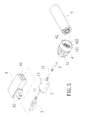
Fig. 5 is an exploded view to show the charging device inFig. 1 of the present invention is connected to an Alternative-Current charger, and -
Fig. 6 is an exploded view to show that the charging device inFig. 3 of the present invention is connected to an Alternative-Current charger. - Referring to
Fig. 1 , the charging device of the present invention comprises acharger 1 and afirst transmission line 11 and asecond transmission line 12 are respectively connected to two ends of thecharger 1. The two respective first ends of the first andsecond transmission lines charger 1. The second end of thefirst transmission line 11 has aUSB connector 2 connected thereto and the second end of thesecond transmission line 12 has aterminal connector 3 connected thereto. Thecharger 1 has anindex light 13 which is electrically connected to the circuit of thecharger 1. Thecharger 1 has abattery connecting unit 4 which has aterminal receptacle 41 and abattery receptacle 42 on two ends thereof, theterminal receptacle 41 and thebattery receptacle 42 are electronically connected to each other. Theterminal receptacles 41 is connected to theconnector 3 of thesecond transmission line 12, and thebattery receptacle 42 has apositive pole member 421 and anegative pole member 422. Thepositive pole member 421 and thenegative pole member 422 may be two respective springs so as to be connected with the positive pole and the negative pole of theLithium battery 5. - When the users want to charge the Lithium batteries of the cellular phones, digital cameras, Personal Digital Assistants or laptop computers, while no receptacles on the walls available, as shown in
Fig. 2 , theterminal connector 3 of thecharger 1 is connected to theterminal receptacle 41 of thebattery connecting unit 4, and thebattery receptacle 42 of thebattery connecting unit 4 is connected to theLithium batteries 5 of theelectronic product 6 to be charged. TheUSB connector 2 of thecharger 1 is then connected to aUSB receptacle 61 of theelectronic product 6. The current of theelectronic product 6 passes theUSB connector 2 of thecharger 1 and thefirst transmission line 11 and is connected to the circuit in thecharger 1. The current then is connected to thebattery connecting unit 4 via theterminal connector 3 of thesecond transmission line 12. Thebattery connecting unit 4 transfers the Direct Current to theLithium batteries 5 of theelectronic product 6 via thebattery receptacle 42. TheLithium batteries 5 are then charged and theindex light 13 on thecharger 1 lights on to show its charging status. When the charging process to theLithium batteries 5 is completed, theindex light 13 on thecharger 1 turns into green to acknowledge the users about the charging status. - When the charging process is completed, the users remove the
Lithium batteries 5 from thebattery receptacle 42 of thebattery connecting unit 4 and theLithium batteries 5 can be installed to theelectronic product 6 and provide power to theelectronic product 6. The charging device allows the users to charge theLithium batteries 5 of theelectronic products 6 withUSB receptacles 61 when needed. - As shown in
Figs. 3 and4 , the charging device can be cooperated with theLithium battery 7 with acharging hole 71. Theterminal connector 3 of thecharger 1 is connected to thecharging hole 71 of theLithium battery 7 and theUSB connector 2 of thechanger 1 is connected to theUSB receptacle 61 of theelectronic product 6. TheLithium battery 7 is charged from theUSB receptacle 61 of theelectronic product 6. - As shown in
Figs. 5 and6 , the charging device can be cooperated with the receptacle on the wall and has an Alternative-Current charger 8 which has aUSB receptacle 81. TheUSB receptacle 81 is connectable to theUSB connector 2 of thecharger 1. The Alternative-Current charger 8 further haslegs 82 which are electrically connectable to theUSB receptacle 81 of the Alternative-Current charger 8. A circuit for transferring the Alternative Current into Direct Current is connected between thelegs 82 and theUSB receptacle 81 of the Alternative-Current charger 8. When charging theLithium batteries 5, theterminal connector 3 of thecharger 1 is connected to theLithium batteries 5 via thebattery connecting unit 4 as shown inFig. 5 . Alternatively, theterminal connector 3 of thecharger 1 is directly connected to theLithium battery 7 with thecharging hole 71 as shown inFig. 6 . Thelegs 82 of the Alternative-Current charger 8 are connected to the receptacle on the wall. The electric power from the receptacle on the wall passes through theUSB connector 2 of thecharger 1 via the Alternative-Current charger 8 and thefirst transmission line 11 and output via the circuit of thecharger 1. The current then passes through thesecond transmission line 12 and charges theLithium battery terminal connector 3. Thebatteries - While we have shown and described the embodiment in accordance with the present invention, it should be clear to those skilled in the art that further embodiments may be made without departing from the scope of the present invention.
Claims (10)
- A charging device comprising:a charger (1), a first transmission line (11) and a second transmission line (12) respectively connected to two ends of the charger (1), two respective first ends of the first and second transmission lines (11, 12) connected with a circuit in the charger (1), a second end of the first transmission line (11) having a USB (Universal Serial Bus) connector (2) connected thereto, a second end of the second transmission line (12) having a connector (3) connected thereto.
- The charging device as claimed in claim 1, wherein the charger device has a battery connecting unit (4) which has two receptacles (41, 42) on two ends thereof, the two receptacles (41, 42) are electronically connected to each other, one of the receptacles is connected to the connector (3) of the second transmission line (12), the other receptacle (42) has a positive pole member and a negative pole member for being connected with a battery.
- The charging device as claimed in claim 2 further comprising an Alternative-Current charger (8) which has a USB receptacle (81) which is connectable to the USB connector (2) of the charger (1), the Alternative-Current charger (8) having legs (82) which are electrically connectable to the USB receptacle (81) of the Alternative-Current charger (8).
- The charging device as claimed in claim 3, wherein the charger (1) has an index light (13) which is electrically connected to the circuit of the charger (1).
- The charging device as claimed in claim 4, wherein the second end of the second transmission line (12) has a terminal connector (3) connected thereto.
- The charging device as claimed in claim 1 further comprising an Alternative-Current charger (8) which has a USB receptacle (81) which is connectable to the USB connector (2) of the charger (1), the Alternative-Current charger (8) having legs (82) which are electrically connectable to the USB receptacle (81) of the Alternative-Current charger (8).
- The charging device as claimed in claim 6, wherein the charger (1) has an index light (13) which is electrically connected to the circuit of the charger (1).
- The charging device as claimed in claim 7, wherein the second end of the second transmission line (12) has a terminal connector (3) connected thereto.
- The charging device as claimed in claim 1, wherein the charger (1) has an index light (13) which is electrically connected to the circuit of the charger (1).
- the charging device as claimed in claim 1, wherein the second end of the second transmission line (12) has a terminal connector (3) connected thereto.
Priority Applications (8)
| Application Number | Priority Date | Filing Date | Title |
|---|---|---|---|
| TW101101917A TW201331756A (en) | 2012-01-18 | 2012-01-18 | USB charging controller |
| CN2012200515521U CN202503326U (en) | 2012-01-18 | 2012-02-17 | USB charging controller |
| CN2012100358987A CN102545343A (en) | 2012-01-18 | 2012-02-17 | A USB charging controller |
| CA2770969A CA2770969A1 (en) | 2012-01-18 | 2012-02-24 | Universal serial bus charging device |
| US13/404,206 US20130221922A1 (en) | 2012-01-18 | 2012-02-24 | Universal serial bus charging device |
| EP12157106.1A EP2632018A1 (en) | 2012-01-18 | 2012-02-27 | Universal serial bus charging device |
| AU2012201270A AU2012201270A1 (en) | 2012-01-18 | 2012-03-02 | Universal serial bus charging device |
| JP2012047911A JP2013183602A (en) | 2012-01-18 | 2012-03-05 | Usb charge control device |
Applications Claiming Priority (8)
| Application Number | Priority Date | Filing Date | Title |
|---|---|---|---|
| TW101101917A TW201331756A (en) | 2012-01-18 | 2012-01-18 | USB charging controller |
| CN2012200515521U CN202503326U (en) | 2012-01-18 | 2012-02-17 | USB charging controller |
| CN2012100358987A CN102545343A (en) | 2012-01-18 | 2012-02-17 | A USB charging controller |
| CA2770969A CA2770969A1 (en) | 2012-01-18 | 2012-02-24 | Universal serial bus charging device |
| US13/404,206 US20130221922A1 (en) | 2012-01-18 | 2012-02-24 | Universal serial bus charging device |
| EP12157106.1A EP2632018A1 (en) | 2012-01-18 | 2012-02-27 | Universal serial bus charging device |
| AU2012201270A AU2012201270A1 (en) | 2012-01-18 | 2012-03-02 | Universal serial bus charging device |
| JP2012047911A JP2013183602A (en) | 2012-01-18 | 2012-03-05 | Usb charge control device |
Publications (1)
| Publication Number | Publication Date |
|---|---|
| EP2632018A1 true EP2632018A1 (en) | 2013-08-28 |
Family
ID=51845605
Family Applications (1)
| Application Number | Title | Priority Date | Filing Date |
|---|---|---|---|
| EP12157106.1A Withdrawn EP2632018A1 (en) | 2012-01-18 | 2012-02-27 | Universal serial bus charging device |
Country Status (7)
| Country | Link |
|---|---|
| US (1) | US20130221922A1 (en) |
| EP (1) | EP2632018A1 (en) |
| JP (1) | JP2013183602A (en) |
| CN (2) | CN202503326U (en) |
| AU (1) | AU2012201270A1 (en) |
| CA (1) | CA2770969A1 (en) |
| TW (1) | TW201331756A (en) |
Cited By (1)
| Publication number | Priority date | Publication date | Assignee | Title |
|---|---|---|---|---|
| EP2876776A1 (en) * | 2013-11-26 | 2015-05-27 | Rainer Böhm | Externally powered battery replacement |
Families Citing this family (5)
| Publication number | Priority date | Publication date | Assignee | Title |
|---|---|---|---|---|
| TWI450470B (en) * | 2011-02-18 | 2014-08-21 | 廣東正飛移動照明有限公司 | Mobile charger |
| TW201331756A (en) * | 2012-01-18 | 2013-08-01 | 廣東正飛移動照明有限公司 | USB charging controller |
| KR101617834B1 (en) * | 2014-10-01 | 2016-05-03 | 정현옥 | Chager for fishing led chemilight |
| US20160233662A1 (en) * | 2015-02-06 | 2016-08-11 | Mathew Inskeep | Jump Starter Auto Safety Jumper Module |
| KR101947638B1 (en) * | 2018-05-17 | 2019-02-13 | 주식회사 라이칸스로프 | Charging device for battery |
Citations (2)
| Publication number | Priority date | Publication date | Assignee | Title |
|---|---|---|---|---|
| US20040251873A1 (en) * | 2003-03-24 | 2004-12-16 | Simoes Felipe O. | Battery charging assembly |
| US20090294150A1 (en) * | 2008-05-27 | 2009-12-03 | Mcginley Valerie | Energy saving cable assemblies |
Family Cites Families (21)
| Publication number | Priority date | Publication date | Assignee | Title |
|---|---|---|---|---|
| TW543994U (en) * | 2001-12-25 | 2003-07-21 | Sheng-Shing Liau | Easy carrying multi-function charger |
| US6626703B2 (en) * | 2002-02-05 | 2003-09-30 | Liao Sheng Hsin | Multipurpose adaptor with a universal serial bus connector |
| US6614206B1 (en) * | 2002-05-23 | 2003-09-02 | Palm, Inc. | Universal USB charging accessory |
| US6894457B2 (en) * | 2002-11-01 | 2005-05-17 | American Power Conversion Corporation | Universal multiple device power adapter and carry case |
| JP2007095417A (en) * | 2005-09-28 | 2007-04-12 | Sony Corp | battery pack |
| JP2007228051A (en) * | 2006-02-21 | 2007-09-06 | Mitsumi Electric Co Ltd | communication cable |
| JP4753817B2 (en) * | 2006-09-05 | 2011-08-24 | 三洋電機株式会社 | Charger |
| US7638971B2 (en) * | 2007-03-22 | 2009-12-29 | Callpod, Inc. | Multiple device battery charger |
| KR20090021518A (en) * | 2007-08-27 | 2009-03-04 | 삼성전자주식회사 | Multi charging device and method |
| US20090102442A1 (en) * | 2007-10-18 | 2009-04-23 | Li-Chun Lai | Power Supply Device for USB |
| TWM348418U (en) * | 2008-06-20 | 2009-01-01 | Cheng Uei Prec Ind Co Ltd | Charger |
| US8107243B2 (en) * | 2008-09-12 | 2012-01-31 | Callpod Inc. | Portable multi-device power supply, battery charger, and docking system |
| CN101789612A (en) * | 2009-01-23 | 2010-07-28 | 刘允钊 | Multipurpose charging device in vehicle and charging method thereof |
| US20120064772A1 (en) * | 2009-06-02 | 2012-03-15 | Pocrass Alan L | Modular cable with integral rechargeable power supply |
| KR20120039502A (en) * | 2009-07-01 | 2012-04-25 | 에이그린씨 피티이 리미티드 | Charging apparatus for electronic devices |
| TWM374222U (en) * | 2009-09-29 | 2010-02-11 | jin-cheng Gao | Portable electronic charging module for replaceable plug connector |
| CN201503895U (en) * | 2009-09-30 | 2010-06-09 | 东莞市盈聚电子有限公司 | Usb charger |
| CN101944633B (en) * | 2010-09-29 | 2012-11-07 | 广东正飞移动照明有限公司 | Lithium ion battery and charger using same |
| TWI450470B (en) * | 2011-02-18 | 2014-08-21 | 廣東正飛移動照明有限公司 | Mobile charger |
| US20130043827A1 (en) * | 2011-08-10 | 2013-02-21 | Nathan Daniel Weinstein | Portable power charger |
| TW201331756A (en) * | 2012-01-18 | 2013-08-01 | 廣東正飛移動照明有限公司 | USB charging controller |
-
2012
- 2012-01-18 TW TW101101917A patent/TW201331756A/en unknown
- 2012-02-17 CN CN2012200515521U patent/CN202503326U/en not_active Expired - Lifetime
- 2012-02-17 CN CN2012100358987A patent/CN102545343A/en active Pending
- 2012-02-24 CA CA2770969A patent/CA2770969A1/en not_active Abandoned
- 2012-02-24 US US13/404,206 patent/US20130221922A1/en not_active Abandoned
- 2012-02-27 EP EP12157106.1A patent/EP2632018A1/en not_active Withdrawn
- 2012-03-02 AU AU2012201270A patent/AU2012201270A1/en not_active Abandoned
- 2012-03-05 JP JP2012047911A patent/JP2013183602A/en active Pending
Patent Citations (2)
| Publication number | Priority date | Publication date | Assignee | Title |
|---|---|---|---|---|
| US20040251873A1 (en) * | 2003-03-24 | 2004-12-16 | Simoes Felipe O. | Battery charging assembly |
| US20090294150A1 (en) * | 2008-05-27 | 2009-12-03 | Mcginley Valerie | Energy saving cable assemblies |
Cited By (1)
| Publication number | Priority date | Publication date | Assignee | Title |
|---|---|---|---|---|
| EP2876776A1 (en) * | 2013-11-26 | 2015-05-27 | Rainer Böhm | Externally powered battery replacement |
Also Published As
| Publication number | Publication date |
|---|---|
| AU2012201270A1 (en) | 2013-09-19 |
| CN202503326U (en) | 2012-10-24 |
| CN102545343A (en) | 2012-07-04 |
| TW201331756A (en) | 2013-08-01 |
| US20130221922A1 (en) | 2013-08-29 |
| CA2770969A1 (en) | 2013-08-24 |
| JP2013183602A (en) | 2013-09-12 |
Similar Documents
| Publication | Publication Date | Title |
|---|---|---|
| KR102315165B1 (en) | Battery packs and chargers, and battery pack kit for power tools | |
| EP2713471A2 (en) | Charger | |
| EP2632018A1 (en) | Universal serial bus charging device | |
| US9401609B2 (en) | Portable power transfer device | |
| CN214204974U (en) | Battery charger | |
| EP2822088A1 (en) | Standby battery product and stackable charging system thereof | |
| CN204497813U (en) | A kind of power brick of electric tool | |
| CN103236720A (en) | Building-block type combination device of mobile power source and charger | |
| US20180083464A1 (en) | Charging case for an electronic device | |
| US20230118788A1 (en) | Free voltage adapter for charging | |
| CN205141745U (en) | Composite power supply | |
| CN203071367U (en) | Mobile device adaptor | |
| US20090134839A1 (en) | Alterable battery charger | |
| CN205377439U (en) | Mobile charging device | |
| CN204481092U (en) | Rechargeable battery pack | |
| CN203707837U (en) | Wireless charger | |
| CN203135518U (en) | Multifunctional mobile phone charger | |
| RU158588U1 (en) | CHARGER | |
| CN203135483U (en) | A multi-interface lithium battery adapter | |
| CN204441922U (en) | Replaceable car rescue power bank | |
| CN202586396U (en) | Double-USB travel charger | |
| US20170179743A1 (en) | Charge-discharge module | |
| CN202524123U (en) | charger | |
| KR20200000508U (en) | Fusion Portable battery charger | |
| TWM508839U (en) | The mobile power supply device |
Legal Events
| Date | Code | Title | Description |
|---|---|---|---|
| PUAI | Public reference made under article 153(3) epc to a published international application that has entered the european phase |
Free format text: ORIGINAL CODE: 0009012 |
|
| AK | Designated contracting states |
Kind code of ref document: A1 Designated state(s): AL AT BE BG CH CY CZ DE DK EE ES FI FR GB GR HR HU IE IS IT LI LT LU LV MC MK MT NL NO PL PT RO RS SE SI SK SM TR |
|
| AX | Request for extension of the european patent |
Extension state: BA ME |
|
| STAA | Information on the status of an ep patent application or granted ep patent |
Free format text: STATUS: THE APPLICATION IS DEEMED TO BE WITHDRAWN |
|
| 18D | Application deemed to be withdrawn |
Effective date: 20140301 |