EP2631989B1 - Managing antennas on an access point in a wireless network - Google Patents
Managing antennas on an access point in a wireless network Download PDFInfo
- Publication number
- EP2631989B1 EP2631989B1 EP12186246.0A EP12186246A EP2631989B1 EP 2631989 B1 EP2631989 B1 EP 2631989B1 EP 12186246 A EP12186246 A EP 12186246A EP 2631989 B1 EP2631989 B1 EP 2631989B1
- Authority
- EP
- European Patent Office
- Prior art keywords
- antenna
- information
- access point
- wireless
- wireless access
- Prior art date
- Legal status (The legal status is an assumption and is not a legal conclusion. Google has not performed a legal analysis and makes no representation as to the accuracy of the status listed.)
- Not-in-force
Links
Images



Classifications
-
- H—ELECTRICITY
- H04—ELECTRIC COMMUNICATION TECHNIQUE
- H04B—TRANSMISSION
- H04B17/00—Monitoring; Testing
- H04B17/10—Monitoring; Testing of transmitters
- H04B17/11—Monitoring; Testing of transmitters for calibration
- H04B17/12—Monitoring; Testing of transmitters for calibration of transmit antennas, e.g. of the amplitude or phase
-
- H—ELECTRICITY
- H01—ELECTRIC ELEMENTS
- H01Q—ANTENNAS, i.e. RADIO AERIALS
- H01Q1/00—Details of, or arrangements associated with, antennas
- H01Q1/12—Supports; Mounting means
- H01Q1/22—Supports; Mounting means by structural association with other equipment or articles
- H01Q1/24—Supports; Mounting means by structural association with other equipment or articles with receiving set
- H01Q1/241—Supports; Mounting means by structural association with other equipment or articles with receiving set used in mobile communications, e.g. GSM
- H01Q1/246—Supports; Mounting means by structural association with other equipment or articles with receiving set used in mobile communications, e.g. GSM specially adapted for base stations
-
- H—ELECTRICITY
- H01—ELECTRIC ELEMENTS
- H01Q—ANTENNAS, i.e. RADIO AERIALS
- H01Q3/00—Arrangements for changing or varying the orientation or the shape of the directional pattern of the waves radiated from an antenna or antenna system
- H01Q3/24—Arrangements for changing or varying the orientation or the shape of the directional pattern of the waves radiated from an antenna or antenna system varying the orientation by switching energy from one active radiating element to another, e.g. for beam switching
-
- H—ELECTRICITY
- H04—ELECTRIC COMMUNICATION TECHNIQUE
- H04W—WIRELESS COMMUNICATION NETWORKS
- H04W88/00—Devices specially adapted for wireless communication networks, e.g. terminals, base stations or access point devices
- H04W88/08—Access point devices
- H04W88/085—Access point devices with remote components
Definitions
- FIG. 3 is a block diagram 300 of a wireless access point 305.
- a wireless access point may include one or more components such as a RFID reader 330 (or other receiver), a memory 315, a processor 320 and antenna management software 325.
- the wireless access point 305 may include one or more communication interfaces 335 to allow the wireless access point 305 to communicate to other devices such as one or more antennas (e.g., external), wireless clients, routers, wireless controllers, etc. across a wireless network such as a WLAN.
- antennas e.g., external
Landscapes
- Engineering & Computer Science (AREA)
- Computer Networks & Wireless Communication (AREA)
- Physics & Mathematics (AREA)
- Electromagnetism (AREA)
- Signal Processing (AREA)
- Mobile Radio Communication Systems (AREA)
Description
- Wireless local area networks (WLANs) are ubiquitous in today's corporate and campus environments. Conventional WLAN architecture includes a router connected to one or more wireless access points. Further, a wireless controller may be connected to the WLAN to control and manage the wireless access points. Certain areas within a corporate and campus environment are not conducive for a wireless client to connect to a wireless access point. This may be due to a blocked line of sight between the client and wireless access point antenna, interference from other clients and RF sources, the distance between client and wireless access point antenna being too great, or other environmental conditions. Thus, for many WLANs, information technology (IT) personnel have chosen to install external antennas across such environments to connect to the wireless access points, either remotely or physically.
- In accordance with the invention there is provided a method according to
claim 1. Further in accordance with the invention there is provided a device according to claim 12. - Examples describe management of antenna connections to a wireless network. In one example, a method includes receiving antenna information from an antenna. For example, the antenna information can be received at a wireless controller of a wireless network. Configuration information is accessed from a database coupled to the wireless controller, where this information includes suitable antenna characteristics for use with the wireless network. The received antenna information and the configuration information are then compared, and instructions are provided to cause the antenna to be connected to or disconnected from the wireless network based on the comparison between the antenna information and the configuration information.
- In another example, a device includes a storage device storing configuration information including suitable antenna characteristics for use with a wireless network. A processor accesses the storage device and receives antenna information from an antenna. The process accesses the configuration information on the storage device and compares the antenna information with the configuration information. The process provides instructions to cause the antenna to be connected to or disconnected from the wireless network based on the comparison between the antenna information and the configuration information.
- In another example, a method includes receiving antenna information from an antenna at a wireless access point of a wireless network. The antenna information describes one or more characteristics of the antenna, and is provided to a wireless controller of the wireless network. Instructions are received from the wireless controller indicating whether the antenna is to be connected to or disconnected from the wireless network based on a comparison between the antenna information and antenna configuration information. If the instructions indicate connection, the antenna is connected to the wireless network or an existing connection is maintained. If the instructions indicate disconnection, the antenna is disconnected from the wireless network or an existing disconnection is maintained.
- The foregoing summary is illustrative only and is not intended to be in any way limiting.
-
WO 03/049228 A1 -
-
Figure 1 is a block diagram of an example wireless local area network; -
Figure 2 is a block diagram of an example antenna according to one embodiment; -
Figure 3 is a block diagram of a wireless access point; -
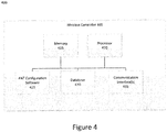
Figure 4 is a block diagram of a wireless controller according to one embodiment; and -
Figure 5 is a flowchart of an example method according to one embodiment. - One or more embodiments described herein relate to management of antennas in a wireless network, including establishing and maintaining network connections to properly-configured antennas. In some embodiments, an antenna can communicate information describing the antenna that is received by a wireless
controller. The controller compares the antenna information to configuration information including suitable antenna characteristics for use with the wireless network, to determine whether or not the antenna is properly configured for use in the network. If the antenna is not suitable, the controller can instruct that the antenna be decoupled and that a different antenna be coupled to the wireless network. - Examples can be implemented in a system including a wireless network and wireless clients connecting to the wireless network. For example, wireless access points may be installed such that wireless clients have access to the wireless network and other connected networks, such as the Internet, from any location. Further, wireless access points may need to be connected or coupled to external antennas in order to provide improved line of sight, reduce interference, or decrease the distance or range to wireless clients that have need to access the wireless network or the Internet. Due to compliance standards, wireless access points may need to access industry/standard compliant external antennas. Therefore, some embodiments may include an identification module coupled to an external antenna that is coupled to the wireless access point. An example identification module may be a radio frequency identification (RFID) module. However, the identification module may be any device that stores identification information associated with a given antenna. The identification module may transmit such antenna information wirelessly (e.g., via radio, Bluetooth, etc.) or through a wired connection. Further, the wireless access point may have a receiver to access or receive the antenna information from the identification module. If the identification module on the antenna is an RFID module, the receiver on the wireless access point may be an RFID reader. Although examples herein are described in the context of an RFID module and an RFID reader, examples can also apply to other types of identification modules and receivers, respectively. In some example embodiments, once the receiver of the wireless access point accesses the antenna information from the identification module, the wireless access point may forward the antenna information to a wireless controller coupled to a database. The wireless controller may access the database to find antenna configuration information for the antenna, where that information describes a suitable configuration of the antenna when used with the wireless network, such as being compliant to known industry standards relevant to the wireless network. The controller can determine whether the received antenna information matches the antenna configuration information from the database. If so, the wireless controller may provide instructions to the wireless access point to maintain connection or access to the external antenna. If not, the wireless controller may provide alternate instructions to the wireless access point to decouple from the external antenna and access or connect to another external antenna.
-
Figure 1 is a block diagram 100 of an example wireless local area network according to one embodiment. The wireless local area network may have multiple subnetworks and cover more than one area of a physical location, such as more than one room, floor, etc. of a building, campus, corporate environment, or other environment. The wireless local area network shownFigure 1 includes two separate wirelesslocal area subnetworks wireless access points external antennas wireless access point router wireless controller 102 is coupled to thewireless access points routers Wireless clients wireless access points antennas local area subnetwork - A
wireless access point external antennas wireless clients antennas wireless access point wireless client antenna wireless client - Each wireless access point uses an antenna suitably and correctly configured for the wireless network. For example, the wireless access point accesses or uses an antenna that conforms to the rules governing its operating standards and rules of the FCC, e.g., rules related to broadcasting signals. In some embodiments, each antenna may have an RFID module that stores antenna information including one or more antenna characteristics or specification information. The module sends the antenna information to the
wireless controller 102 to determine whether the antenna is suitably configured for operation with the wireless network and to comply with standards' rules and the FCC. In some embodiments, the antennas and the wireless access points can communicate with each other using a communication channel separate from the wireless network. For example, thewireless access points antenna wireless access points wireless controller 102. Thewireless controller 102 may determine whether the received antenna information complies with the FCC rules and its operating standards. In some examples thewireless controller 102 determines such compliance by comparing the received antenna information with accessed antenna configuration information, which can be stored on a connected storage device such as a database. If the received antenna information matches the antenna configuration information thenwireless controller 102 may provide instructions to the wireless access point to maintain connection and access to the antenna, or to connect to the antenna (if not already connected to the wireless network). However, if the received antenna information does not match the antenna configuration information thenwireless controller 102 may provide instructions for the wireless access point to decouple or disconnect from the respective external antenna (or maintain disconnection if the antenna is not already connected to the wireless network) and connect to or access another external antenna. - In some embodiments, the antenna information provided by the identification module may include a type of the antenna, one or more frequencies at which the antenna receives data, and a signal range for the antenna. Similarly, the antenna configuration information stored in the database may include a configured antenna type, one or more configured frequencies at which the antenna receives data, and a configured signal range for the antenna. The antenna can be any type that includes, but is not limited to, directional antenna, omni-directional antenna, point-to-point antenna, point-to-multipoint antenna, home office, mobile WiFi, Yagi antenna, Backfire antenna, and parabolic antenna.
- One of ordinary skill in the art can recognize that to extend the range of a wireless access point's connectivity to a wireless client, installing one or more external antennas may be required. Further, the external antennas may be coupled to the wireless access point, thereby extending wireless network and Internet access to areas of the physical location (e.g., room, floor, etc. of a corporate environment) that otherwise may not have access. Such an external antenna may have increased gain and directional or omni-directional qualities. Directional antennas are used for point-to-point or sometimes for multi-point systems, depending on the wireless environment. Omni-directional antennas are a common "base" antenna used for point-to-multi-point systems. For example, an omni-directional antenna can serve as primary antenna to distribute wireless signals to other computers or devices (such as wireless printers, PDAs, etc.) in a corporate environment.
- Point-to-point systems usually involve two different wireless access points. If a wireless access point is across a long RF valley and the WLAN architecture is designed for multiple users to share the connection with multiple users on the other side of the valley, then external antennas may be configured as a multi-point system using directional antennas. Point-to-multi-point systems are often used in WLAN environments.
- The range of the wireless signal using external antennas may depend on several factors, including power output of a wireless card on a wireless client or router, receiver sensitivity of the wireless cards (or other devices) receiving signals, and obstructions which may inhibit the transmission path.
- Yagi antennas are typically very directional and are used for point-to-point signals, or to extend the range of a point-to-multi-point system. Another antenna type is a backfire antenna, which is a small directional antenna with increased gain, and may have a parabolic dish shape. Backfire antennas can be used for point-to-point or point-to-multipoint systems because of their increased gain and increased signal-to-noise ratios. Traditionally, parabolic dish antennas output high gain but may be difficult to maintain connectivity, because as the gain of an antenna increases, the antenna's radiation pattern decreases until a relatively small window remains to point or aim the antenna to wireless client locations. Dish antennas can be used for a point-to-point system for long haul systems. Parabolic dish antennas work by focusing the power to a central point and beaming the radio's signal to a specific area. These antennas are highly focused and are suitable for long range applications.
- The gain necessary for each individual WiFi antenna system may depend on line of sight obstruction, range, distance, and/or the receive strength or sensitivity of wireless cards or other receiver devices. Further, as with all radio systems, interference may be an issue. Foreign sources that may cause interference with WiFi systems include microwave ovens, certain lighting systems, other 802.11 access points or systems, microwave transmitters, and high speed processors for computers.
- The characteristics of the different types of antennas described herein show that different antennas may be suitable for different conditions to increase the range of connectivity to wireless clients in certain physical areas that otherwise may not have access to the wireless network or the Internet.
-
Figure 2 is a block diagram 200 of anexample antenna 205 according to one embodiment. Theantenna 205 may be an external antenna connected to a wireless access point to provide better connectivity to one or more wireless clients. As described herein, the wireless access point may retrieve antenna information describing or otherwise associated with theantenna 205, which includes characteristics (e.g. specification information) of the antenna such as a type of theantenna 205, one or more frequencies at which the antenna receives data, a range for the antenna, and/or any other antenna specifications. In some embodiments, this antenna information is stored in an identification module on (or closely connected to) theantenna 205. For example, the identification module can be anRFID module 210 provided on the antenna. The RFID module 210 (which can be an RFID tag) may include aprocessor 220 as well as amemory 215 that stores the antenna information. When communicating with a wireless access point requesting the antenna information,RFID software 225 embedded in the RFID module may assist in transferring the antenna information to the wireless access point. The wireless access point may relay such information to a wireless controller so that the wireless controller may determine whether the antenna is suitable for use in the wireless network system. -
Figure 3 is a block diagram 300 of awireless access point 305. Such a wireless access point may include one or more components such as a RFID reader 330 (or other receiver), amemory 315, aprocessor 320 andantenna management software 325. Further, thewireless access point 305 may include one ormore communication interfaces 335 to allow thewireless access point 305 to communicate to other devices such as one or more antennas (e.g., external), wireless clients, routers, wireless controllers, etc. across a wireless network such as a WLAN. - The
wireless access point 305 may be used to retrieve the antenna information stored in the identification module of an antenna using theRFID reader 330. Theantenna management software 325 may be used to send the antenna information to the wireless controller through one or more communication interfaces such that the wireless controller can determine whether the antenna is correctly configured for the network, e.g., complies with rules and FCC regulations. Thewireless access point 305 may receive instructions from the wireless controller to decouple or disconnect the wireless access point from the antenna based on the received antenna information not matching the stored antenna configuration information. Alternatively, thewireless access point 305 may receive instructions from the wireless controller to maintain connectivity of the wireless access point to the antenna (or to connect the wireless access point to the antenna) based on the received antenna information matching the stored antenna configuration information. The management of the decoupling or maintaining the connectivity to the antenna may be performed by theantenna management software 325. -
Figure 4 is a block diagram 400 of awireless controller 405 according to one embodiment.Wireless controller 405 may include several components such as amemory 415, aprocessor 420, and antenna configuration software 425. In some examples, thewireless controller 405 may have adatabase 430 residing in its memory or in connected memory (such as memory 415), where thedatabase 430 stores antenna configuration information. Alternate examples may have thedatabase 430 housed in a separate device and coupled to thewireless controller 405. -
Wireless controller 405 includes one ormore communication interfaces 435 that enable communication with other wireless clients, wireless access points, and routers across the WLAN. Thewireless controller 405 may receive antenna information from the wireless access point that was retrieved from an identification module residing on a connected or accessible external antenna, where the received antenna information describes operating characteristics of a connected (or accessible) antenna. In other embodiments, thewireless controller 405 can receive the antenna information from other components or from the antenna itself. Using the antenna configuration software, thewireless controller 405 can determine whether the received antenna information complies with operating standards and FCC rules based on a comparison with suitable antenna configuration information stored in thedatabase 430. - The antenna configuration information stored in
database 430 can include characteristics, specifications and/or other antenna information that is considered compliant with the operation of wireless network and/or industry standards and rules. In some examples, wireless network standards can require particular antenna characteristics. Some examples can require antenna compliance with FCC rules for broadcasting wireless signals. In some examples, the stored configuration information can include one or more types of antenna characteristics suitable for operation with the wireless network. These characteristics can include one or more types of antennas that are known to function properly with the particular implementation of the wireless network as well as known to be compliant with relevant standards and rules. The stored configuration information can also include one or more frequencies, or frequency ranges, at which the antenna should operate to be compliant with the wireless network and relevant standards and rules. Furthermore, the stored configuration information can include a signal range at which the antenna should be able to transmit and/or receive signals to be compliant with the wireless network and relevant standards and rules. Additional and/or other antenna configuration information can be stored, e.g., characteristics (specification information) related to signal transmission and/or reception, signal power, transmitted or received signal noise, physical dimensions, and/or other characteristics of one or more antennas suitable for operation with the wireless network. In some examples different antenna configuration information can be stored for different particular wireless access points or other components of the wireless network system, and in such cases identifying information can be received by the wireless controller to identify the particular wireless access point and/or particular antenna. - The
wireless controller 405 compares the received antenna information to the stored antenna configuration information. In some embodiments, thecontroller 405 compares each antenna characteristic of the received antenna information to corresponding characteristics of the stored configuration information. For example, the received antenna characteristics can be compared to each of the stored antenna types, frequency ranges, signal ranges, etc., or compared to each set of these characteristics. These comparisons are performed until a match is found for each received characteristic or set of characteristics, or until all stored configuration information has been compared and a match is not found for one or more of the characteristics. Thewireless controller 405 may provide instructions to the wireless access point to decouple or disconnect the wireless access point from the antenna based on the associated antenna information not matching the antenna configuration information. Alternatively, thewireless controller 405 may provide instructions to the wireless access point to maintain connectivity to the antenna (or connect to the antenna if not already connected) based on the associated antenna information matching the antenna configuration information. - In some embodiments, the wireless access controller can connect multiple antennas to the wireless network. Each such antenna is checked to match with the stored configuration information and is disconnected or not connected if a match is not found.
-
Figure 5 is aflowchart 500 of an example method according to one embodiment. In one step of the example method, a wireless access point can access and receive antenna information from an identification module of an external antenna using a receiver of the wireless access point, as shown inblock 502. A further step may include transmitting the antenna information to a wireless controller in the WLAN, as shown in block 504. Atdecision 506, the wireless controller accesses antenna configuration information from a database and determines whether the antenna information matches the accessed antenna configuration information, where a match indicates that the antenna is in compliance with appropriate operating standards and FCC rules as well as being otherwise suitable for use in the wireless network. If there is no such match, then the wireless access controller provides instructions to the wireless access point to decouple or disconnect the wireless access point from the antenna, as shown inblock 508. In some cases, the antenna may not be already connected to the wireless access point, and the instructions can inform the wireless access point to maintain this disconnected state (and/or instructions such as an acknowledgement can be sent back to the wireless access point, causing no action). - If there is a match, the wireless controller provides instructions to the wireless access point to maintain connectivity to the antenna, as shown in block 510. In some cases, the antenna may not already be connected to the wireless network, and the instructions cause the wireless access point to connect the antenna to the wireless network (such as to connect to the wireless access point).
- After
block 508 or 510, the method can return to block 502 to receive antenna information from a different antenna having communication with the wireless access point and/or wireless controller, and the following steps can determine whether this different antenna is suitable for connection to the wireless network and, if so, perform the appropriate connection or disconnection. Thus, multiple antennas can be similarly checked. - In the foregoing detailed description, reference is made to the accompanying drawings. In the drawings, similar symbols typically identify similar components, unless context dictates otherwise.
- Note that the functional blocks, methods, devices and systems described in the present disclosure may be integrated or divided into different combination of systems, devices, and functional blocks as would be known to those skilled in the art.
- In general, it should be understood that the devices and circuits described herein may be implemented in hardware using integrated circuit development technologies, or yet via some other methods, or the combination of hardware and software objects that could be ordered, parameterized, and connected in a software environment to implement different functions described herein. For example, the present application may be implemented using one or more general purpose or dedicated processors running a software application through one or more volatile or non-volatile memories. Also, the hardware objects could communicate using electrical signals, with states of the signals representing different data.
- Further, many of the elements that are described are functional entities that may be implemented as discrete or distributed components or in conjunction with other components, in any suitable combination and location.
- With respect to the use of substantially any plural and/or singular terms herein, those having skill in the art can translate from the plural to the singular and/or from the singular to the plural as is appropriate to the context and/or application. The various singular/plural permutations may be expressly set forth herein for sake of clarity.
- While various aspects and embodiments have been disclosed herein, other aspects and embodiments will be apparent to those skilled in the art. The various aspects and embodiments disclosed herein are for purposes of illustration and are not intended to be limiting, with the true scope being indicated by the following claims.
Claims (15)
- A method comprising:receiving antenna information from an antenna, wherein the antenna information is received at a wireless controller of a wireless network;accessing antenna configuration information from a database coupled to the wireless controller, wherein the antenna configuration information includes suitable antenna characteristics for use with the wireless network;comparing the antenna information and the antenna configuration information; and the method further characterized by providing instructions to a wireless access point to cause the antenna to be connected to or disconnected from the wireless access point based on the comparison between the antenna information and the antenna configuration information.
- The method of claim 1, further comprising:determining that the antenna information does not match the antenna configuration information based on the comparison of the antenna information and the antenna configuration information, andwherein the providing instructions cause the antenna to be disconnected from the wireless access point.
- The method of claim 1, further comprising:determining that the antenna information matches the antenna configuration information based on the comparison of the antenna information and the antenna configuration information; andwherein the providing instructions cause the antenna to be connected to the wireless access point.
- The method of claim 1 further comprising determining whether the antenna information matches the antenna configuration information, and wherein the providing instructions include:in response to the antenna information matching the antenna configuration information, providing instructions to maintain a connection of the antenna to the wireless network or to connect the antenna to the wireless network; andin response to the antenna information not matching the antenna configuration information, providing instructions to disconnect the antenna from the wireless access point or to not connect the antenna to the wireless access point.
- The method of claim 1 wherein the antenna is a first antenna, and further comprising:determining that the first antenna is to be disconnected from the wireless network based on the comparison between the antenna information and the antenna configuration information; andconnecting a second antenna to the wireless access point.
- The method of claim 1 wherein the wireless controller is coupled to the wireless access point, and wherein the antenna information is received from the wireless access point.
- The method of claim 1 wherein the antenna information is received using a communication channel separate from the wireless network.
- The method of claim 7 wherein the antenna information is received from a radio frequency identification, RFID, module provided on the antenna.
- The method of claim 1 wherein the antenna information and the suitable antenna characteristics for use with the wireless network include at least one of: an antenna type, an antenna operating frequency range, and an antenna signal range.
- The method of claim 9, wherein the antenna type can be selected from the group consisting of directional antenna, omni-directional antenna, point-to-point antenna, point-to-multipoint antenna, home office, mobile WiFi, Yagi antenna, Backfire antenna, and parabolic antenna.
- The method of claim 1 wherein the suitable antenna characteristics for use with the wireless network are compliant with standards for operating the wireless network.
- A device comprising:a storage device having means for storing antenna configuration information including suitable antenna characteristics for use with a wireless network; andat least one processor having means for accessing the storage device and operative to perform operations comprising:means for receiving antenna information from an antenna;means for accessing the antenna configuration information stored by the storage device;means for comparing the antenna information with the antenna configuration information; andthe device further characterized by means for providing instructions to a wireless access point to cause the antenna to be connected to or disconnected from the wireless access point based on the comparison between the antenna information and the antenna configuration information.
- The device of claim 12 wherein the processor further has means for determining whether the antenna information matches the antenna configuration information, and wherein the means for providing instructions include:in response to the antenna information matching the antenna configuration information, means for providing instructions to maintain a connection of the antenna to the wireless access point or to connect the antenna to the wireless access point; andin response to the antenna information not matching the antenna configuration information, means for providing instructions to disconnect the antenna from the wireless access point or not connect the antenna to the wireless access point and to connecting a second antenna to the wireless access point.
- The device of claim 13 wherein the antenna information is received from the wireless access point of the wireless network.
- The device of claim 14 wherein the antenna information is received using a communication channel coupled between the antenna and the wireless access point, the communication channel being separate from the wireless network.
Applications Claiming Priority (1)
| Application Number | Priority Date | Filing Date | Title |
|---|---|---|---|
| US13/401,772 US9225442B2 (en) | 2012-02-21 | 2012-02-21 | Managing antennas on an access point in a wireless network |
Publications (2)
| Publication Number | Publication Date |
|---|---|
| EP2631989A1 EP2631989A1 (en) | 2013-08-28 |
| EP2631989B1 true EP2631989B1 (en) | 2017-04-19 |
Family
ID=47074631
Family Applications (1)
| Application Number | Title | Priority Date | Filing Date |
|---|---|---|---|
| EP12186246.0A Not-in-force EP2631989B1 (en) | 2012-02-21 | 2012-09-27 | Managing antennas on an access point in a wireless network |
Country Status (2)
| Country | Link |
|---|---|
| US (1) | US9225442B2 (en) |
| EP (1) | EP2631989B1 (en) |
Families Citing this family (7)
| Publication number | Priority date | Publication date | Assignee | Title |
|---|---|---|---|---|
| WO2013187741A1 (en) * | 2012-06-15 | 2013-12-19 | Lg Electronics Inc. | Method and device for transmitting and receiving multi-input multi-output (mimo) signal in wireless communication system in which plural communication systems are present |
| GB2516617B (en) * | 2013-06-12 | 2018-02-21 | Analog Devices Global | Communication unit or method for identifying a connectivity relationship between a logical channel and an antenna element of an active antenna system |
| BR112016019409B1 (en) * | 2014-05-16 | 2023-02-14 | Huawei Technologies Co., Ltd | CABINET SERVER AND DATA CENTER BASED ON CABINET SERVER |
| US10374685B2 (en) * | 2017-02-14 | 2019-08-06 | Arris Enterprises Llc | Dynamic Selection of a receive antenna pattern |
| CN107404402B (en) * | 2017-07-21 | 2022-12-13 | 沈阳邦粹科技有限公司 | Function configuration method and device of router |
| EP4462304B1 (en) * | 2023-05-09 | 2025-04-02 | Sick Ag | Testing and customizing an rfid reader |
| US20260080200A1 (en) * | 2024-09-13 | 2026-03-19 | Trovan Limited | System and methods for a biothermal rfid sensor |
Family Cites Families (8)
| Publication number | Priority date | Publication date | Assignee | Title |
|---|---|---|---|---|
| US6654384B1 (en) * | 1999-12-30 | 2003-11-25 | Aperto Networks, Inc. | Integrated self-optimizing multi-parameter and multi-variable point to multipoint communication system |
| US6853197B1 (en) | 2001-12-03 | 2005-02-08 | Atheros Communications, Inc. | Method and apparatus for insuring integrity of a connectorized antenna |
| US7366304B2 (en) * | 2003-10-07 | 2008-04-29 | Lenovo (Singapore) Pte. Ltd. | Cruable U-NII wireless radio with secure, integral antenna connection via SM BIOS in U-NII wireless ready device |
| US8666445B2 (en) * | 2005-10-25 | 2014-03-04 | Kyocera Corporation | Apparatus, system, and method for transmission antenna switching in a portable communication device |
| US20070141997A1 (en) * | 2005-12-15 | 2007-06-21 | Symbol Technologies, Inc. | Radio frequency identification (RFID) antenna integration techniques in mobile devices |
| CN1983857A (en) | 2006-04-05 | 2007-06-20 | 华为技术有限公司 | Method and device for configuring parameter of antenna equipment |
| JP2010539857A (en) * | 2007-09-17 | 2010-12-16 | クゥアルコム・インコーポレイテッド | Transmitter and receiver for wireless energy transmission |
| US8108020B2 (en) * | 2009-05-08 | 2012-01-31 | Cisco Technology, Inc. | Identification of an antenna |
-
2012
- 2012-02-21 US US13/401,772 patent/US9225442B2/en not_active Expired - Fee Related
- 2012-09-27 EP EP12186246.0A patent/EP2631989B1/en not_active Not-in-force
Non-Patent Citations (1)
| Title |
|---|
| None * |
Also Published As
| Publication number | Publication date |
|---|---|
| US20130215876A1 (en) | 2013-08-22 |
| US9225442B2 (en) | 2015-12-29 |
| EP2631989A1 (en) | 2013-08-28 |
Similar Documents
| Publication | Publication Date | Title |
|---|---|---|
| US9225442B2 (en) | Managing antennas on an access point in a wireless network | |
| US10070445B2 (en) | Access point, wireless communication method, and program | |
| CN105992236B (en) | Electronic device and method for performing wireless communication using beamforming | |
| US9860772B2 (en) | Method and apparatus for determining connection relationship between an antenna feeding port of base station and an antenna port | |
| CN103488188A (en) | Wireless router and method of adjusting wireless router signal transmission | |
| US20080008109A1 (en) | Method and apparatus for bridging wireless control networks | |
| CN103067055A (en) | Bluetooth connecting method and mobile terminal | |
| CN107801253B (en) | Device pairing method, device pairing apparatus and computer-readable storage medium | |
| US20120038513A1 (en) | Centralized antenna interface for wireless networks | |
| US11177861B2 (en) | Electronic device and control method therefor | |
| US9686639B2 (en) | Transmission system using bluetooth low energy technique | |
| CN105722204A (en) | Signal coverage control method and system of WiFi access point | |
| EP2122945B1 (en) | Method and system of communication employing spatial reuse reservation protocol | |
| CN103701500B (en) | Method for read/write device in RFID device for the configuration and read/write device | |
| EP3447928B1 (en) | Routing configuration method and apparatus for non-contact application | |
| JP7429878B2 (en) | Location estimation systems, fixed wireless devices, and mobile wireless devices | |
| US20110305175A1 (en) | Self-contained antenna device with quick aiming switching | |
| EP3454619B1 (en) | Method and system for realizing communication between antenna cloud nodes in indoor high-density network | |
| CN110167038B (en) | Method for topology determination in a mobile radio station and mobile radio station | |
| EP3018969B1 (en) | Communication terminal, communication method, and program | |
| JP2025530989A (en) | Smart Repeater Backhaul Link Control | |
| EP3383129B1 (en) | Master-slave type network-based method and apparatus for selecting management frame antenna | |
| US9877355B2 (en) | Wireless communicator connectable to different types of wireless communication networks | |
| WO2018189171A1 (en) | Automated asset tracking | |
| EP3648373B1 (en) | Repeater for mesh network |
Legal Events
| Date | Code | Title | Description |
|---|---|---|---|
| PUAI | Public reference made under article 153(3) epc to a published international application that has entered the european phase |
Free format text: ORIGINAL CODE: 0009012 |
|
| AK | Designated contracting states |
Kind code of ref document: A1 Designated state(s): AL AT BE BG CH CY CZ DE DK EE ES FI FR GB GR HR HU IE IS IT LI LT LU LV MC MK MT NL NO PL PT RO RS SE SI SK SM TR |
|
| AX | Request for extension of the european patent |
Extension state: BA ME |
|
| 17P | Request for examination filed |
Effective date: 20140227 |
|
| RBV | Designated contracting states (corrected) |
Designated state(s): AL AT BE BG CH CY CZ DE DK EE ES FI FR GB GR HR HU IE IS IT LI LT LU LV MC MK MT NL NO PL PT RO RS SE SI SK SM TR |
|
| REG | Reference to a national code |
Ref country code: DE Ref legal event code: R079 Ref document number: 602012031264 Country of ref document: DE Free format text: PREVIOUS MAIN CLASS: H01Q0001000000 Ipc: H01Q0001240000 |
|
| GRAP | Despatch of communication of intention to grant a patent |
Free format text: ORIGINAL CODE: EPIDOSNIGR1 |
|
| STAA | Information on the status of an ep patent application or granted ep patent |
Free format text: STATUS: GRANT OF PATENT IS INTENDED |
|
| RIC1 | Information provided on ipc code assigned before grant |
Ipc: H01Q 1/24 20060101AFI20161014BHEP |
|
| INTG | Intention to grant announced |
Effective date: 20161103 |
|
| GRAS | Grant fee paid |
Free format text: ORIGINAL CODE: EPIDOSNIGR3 |
|
| GRAA | (expected) grant |
Free format text: ORIGINAL CODE: 0009210 |
|
| STAA | Information on the status of an ep patent application or granted ep patent |
Free format text: STATUS: THE PATENT HAS BEEN GRANTED |
|
| AK | Designated contracting states |
Kind code of ref document: B1 Designated state(s): AL AT BE BG CH CY CZ DE DK EE ES FI FR GB GR HR HU IE IS IT LI LT LU LV MC MK MT NL NO PL PT RO RS SE SI SK SM TR |
|
| REG | Reference to a national code |
Ref country code: GB Ref legal event code: FG4D |
|
| REG | Reference to a national code |
Ref country code: CH Ref legal event code: EP |
|
| REG | Reference to a national code |
Ref country code: AT Ref legal event code: REF Ref document number: 886753 Country of ref document: AT Kind code of ref document: T Effective date: 20170515 |
|
| REG | Reference to a national code |
Ref country code: IE Ref legal event code: FG4D |
|
| REG | Reference to a national code |
Ref country code: DE Ref legal event code: R096 Ref document number: 602012031264 Country of ref document: DE |
|
| REG | Reference to a national code |
Ref country code: NL Ref legal event code: MP Effective date: 20170419 |
|
| REG | Reference to a national code |
Ref country code: LT Ref legal event code: MG4D |
|
| REG | Reference to a national code |
Ref country code: AT Ref legal event code: MK05 Ref document number: 886753 Country of ref document: AT Kind code of ref document: T Effective date: 20170419 |
|
| PG25 | Lapsed in a contracting state [announced via postgrant information from national office to epo] |
Ref country code: NL Free format text: LAPSE BECAUSE OF FAILURE TO SUBMIT A TRANSLATION OF THE DESCRIPTION OR TO PAY THE FEE WITHIN THE PRESCRIBED TIME-LIMIT Effective date: 20170419 |
|
| PG25 | Lapsed in a contracting state [announced via postgrant information from national office to epo] |
Ref country code: ES Free format text: LAPSE BECAUSE OF FAILURE TO SUBMIT A TRANSLATION OF THE DESCRIPTION OR TO PAY THE FEE WITHIN THE PRESCRIBED TIME-LIMIT Effective date: 20170419 Ref country code: HR Free format text: LAPSE BECAUSE OF FAILURE TO SUBMIT A TRANSLATION OF THE DESCRIPTION OR TO PAY THE FEE WITHIN THE PRESCRIBED TIME-LIMIT Effective date: 20170419 Ref country code: GR Free format text: LAPSE BECAUSE OF FAILURE TO SUBMIT A TRANSLATION OF THE DESCRIPTION OR TO PAY THE FEE WITHIN THE PRESCRIBED TIME-LIMIT Effective date: 20170720 Ref country code: LT Free format text: LAPSE BECAUSE OF FAILURE TO SUBMIT A TRANSLATION OF THE DESCRIPTION OR TO PAY THE FEE WITHIN THE PRESCRIBED TIME-LIMIT Effective date: 20170419 Ref country code: AT Free format text: LAPSE BECAUSE OF FAILURE TO SUBMIT A TRANSLATION OF THE DESCRIPTION OR TO PAY THE FEE WITHIN THE PRESCRIBED TIME-LIMIT Effective date: 20170419 Ref country code: FI Free format text: LAPSE BECAUSE OF FAILURE TO SUBMIT A TRANSLATION OF THE DESCRIPTION OR TO PAY THE FEE WITHIN THE PRESCRIBED TIME-LIMIT Effective date: 20170419 Ref country code: NO Free format text: LAPSE BECAUSE OF FAILURE TO SUBMIT A TRANSLATION OF THE DESCRIPTION OR TO PAY THE FEE WITHIN THE PRESCRIBED TIME-LIMIT Effective date: 20170719 |
|
| PG25 | Lapsed in a contracting state [announced via postgrant information from national office to epo] |
Ref country code: PL Free format text: LAPSE BECAUSE OF FAILURE TO SUBMIT A TRANSLATION OF THE DESCRIPTION OR TO PAY THE FEE WITHIN THE PRESCRIBED TIME-LIMIT Effective date: 20170419 Ref country code: IS Free format text: LAPSE BECAUSE OF FAILURE TO SUBMIT A TRANSLATION OF THE DESCRIPTION OR TO PAY THE FEE WITHIN THE PRESCRIBED TIME-LIMIT Effective date: 20170819 Ref country code: RS Free format text: LAPSE BECAUSE OF FAILURE TO SUBMIT A TRANSLATION OF THE DESCRIPTION OR TO PAY THE FEE WITHIN THE PRESCRIBED TIME-LIMIT Effective date: 20170419 Ref country code: SE Free format text: LAPSE BECAUSE OF FAILURE TO SUBMIT A TRANSLATION OF THE DESCRIPTION OR TO PAY THE FEE WITHIN THE PRESCRIBED TIME-LIMIT Effective date: 20170419 Ref country code: LV Free format text: LAPSE BECAUSE OF FAILURE TO SUBMIT A TRANSLATION OF THE DESCRIPTION OR TO PAY THE FEE WITHIN THE PRESCRIBED TIME-LIMIT Effective date: 20170419 Ref country code: BG Free format text: LAPSE BECAUSE OF FAILURE TO SUBMIT A TRANSLATION OF THE DESCRIPTION OR TO PAY THE FEE WITHIN THE PRESCRIBED TIME-LIMIT Effective date: 20170719 |
|
| REG | Reference to a national code |
Ref country code: DE Ref legal event code: R097 Ref document number: 602012031264 Country of ref document: DE |
|
| PG25 | Lapsed in a contracting state [announced via postgrant information from national office to epo] |
Ref country code: RO Free format text: LAPSE BECAUSE OF FAILURE TO SUBMIT A TRANSLATION OF THE DESCRIPTION OR TO PAY THE FEE WITHIN THE PRESCRIBED TIME-LIMIT Effective date: 20170419 Ref country code: DK Free format text: LAPSE BECAUSE OF FAILURE TO SUBMIT A TRANSLATION OF THE DESCRIPTION OR TO PAY THE FEE WITHIN THE PRESCRIBED TIME-LIMIT Effective date: 20170419 Ref country code: CZ Free format text: LAPSE BECAUSE OF FAILURE TO SUBMIT A TRANSLATION OF THE DESCRIPTION OR TO PAY THE FEE WITHIN THE PRESCRIBED TIME-LIMIT Effective date: 20170419 Ref country code: SK Free format text: LAPSE BECAUSE OF FAILURE TO SUBMIT A TRANSLATION OF THE DESCRIPTION OR TO PAY THE FEE WITHIN THE PRESCRIBED TIME-LIMIT Effective date: 20170419 Ref country code: EE Free format text: LAPSE BECAUSE OF FAILURE TO SUBMIT A TRANSLATION OF THE DESCRIPTION OR TO PAY THE FEE WITHIN THE PRESCRIBED TIME-LIMIT Effective date: 20170419 |
|
| PLBE | No opposition filed within time limit |
Free format text: ORIGINAL CODE: 0009261 |
|
| STAA | Information on the status of an ep patent application or granted ep patent |
Free format text: STATUS: NO OPPOSITION FILED WITHIN TIME LIMIT |
|
| PG25 | Lapsed in a contracting state [announced via postgrant information from national office to epo] |
Ref country code: SM Free format text: LAPSE BECAUSE OF FAILURE TO SUBMIT A TRANSLATION OF THE DESCRIPTION OR TO PAY THE FEE WITHIN THE PRESCRIBED TIME-LIMIT Effective date: 20170419 Ref country code: IT Free format text: LAPSE BECAUSE OF FAILURE TO SUBMIT A TRANSLATION OF THE DESCRIPTION OR TO PAY THE FEE WITHIN THE PRESCRIBED TIME-LIMIT Effective date: 20170419 |
|
| 26N | No opposition filed |
Effective date: 20180122 |
|
| REG | Reference to a national code |
Ref country code: CH Ref legal event code: PL |
|
| PG25 | Lapsed in a contracting state [announced via postgrant information from national office to epo] |
Ref country code: SI Free format text: LAPSE BECAUSE OF FAILURE TO SUBMIT A TRANSLATION OF THE DESCRIPTION OR TO PAY THE FEE WITHIN THE PRESCRIBED TIME-LIMIT Effective date: 20170419 Ref country code: MC Free format text: LAPSE BECAUSE OF FAILURE TO SUBMIT A TRANSLATION OF THE DESCRIPTION OR TO PAY THE FEE WITHIN THE PRESCRIBED TIME-LIMIT Effective date: 20170419 |
|
| REG | Reference to a national code |
Ref country code: IE Ref legal event code: MM4A |
|
| REG | Reference to a national code |
Ref country code: BE Ref legal event code: MM Effective date: 20170930 |
|
| PG25 | Lapsed in a contracting state [announced via postgrant information from national office to epo] |
Ref country code: LU Free format text: LAPSE BECAUSE OF NON-PAYMENT OF DUE FEES Effective date: 20170927 |
|
| REG | Reference to a national code |
Ref country code: FR Ref legal event code: ST Effective date: 20180531 |
|
| PG25 | Lapsed in a contracting state [announced via postgrant information from national office to epo] |
Ref country code: LI Free format text: LAPSE BECAUSE OF NON-PAYMENT OF DUE FEES Effective date: 20170930 Ref country code: CH Free format text: LAPSE BECAUSE OF NON-PAYMENT OF DUE FEES Effective date: 20170930 Ref country code: IE Free format text: LAPSE BECAUSE OF NON-PAYMENT OF DUE FEES Effective date: 20170927 |
|
| PG25 | Lapsed in a contracting state [announced via postgrant information from national office to epo] |
Ref country code: BE Free format text: LAPSE BECAUSE OF NON-PAYMENT OF DUE FEES Effective date: 20170930 Ref country code: FR Free format text: LAPSE BECAUSE OF NON-PAYMENT OF DUE FEES Effective date: 20171002 |
|
| PG25 | Lapsed in a contracting state [announced via postgrant information from national office to epo] |
Ref country code: MT Free format text: LAPSE BECAUSE OF NON-PAYMENT OF DUE FEES Effective date: 20170927 |
|
| REG | Reference to a national code |
Ref country code: DE Ref legal event code: R082 Ref document number: 602012031264 Country of ref document: DE Representative=s name: PAGE, WHITE & FARRER GERMANY LLP, DE |
|
| PG25 | Lapsed in a contracting state [announced via postgrant information from national office to epo] |
Ref country code: HU Free format text: LAPSE BECAUSE OF FAILURE TO SUBMIT A TRANSLATION OF THE DESCRIPTION OR TO PAY THE FEE WITHIN THE PRESCRIBED TIME-LIMIT; INVALID AB INITIO Effective date: 20120927 |
|
| PG25 | Lapsed in a contracting state [announced via postgrant information from national office to epo] |
Ref country code: CY Free format text: LAPSE BECAUSE OF NON-PAYMENT OF DUE FEES Effective date: 20170419 |
|
| PG25 | Lapsed in a contracting state [announced via postgrant information from national office to epo] |
Ref country code: MK Free format text: LAPSE BECAUSE OF FAILURE TO SUBMIT A TRANSLATION OF THE DESCRIPTION OR TO PAY THE FEE WITHIN THE PRESCRIBED TIME-LIMIT Effective date: 20170419 |
|
| PG25 | Lapsed in a contracting state [announced via postgrant information from national office to epo] |
Ref country code: TR Free format text: LAPSE BECAUSE OF FAILURE TO SUBMIT A TRANSLATION OF THE DESCRIPTION OR TO PAY THE FEE WITHIN THE PRESCRIBED TIME-LIMIT Effective date: 20170419 |
|
| PG25 | Lapsed in a contracting state [announced via postgrant information from national office to epo] |
Ref country code: PT Free format text: LAPSE BECAUSE OF FAILURE TO SUBMIT A TRANSLATION OF THE DESCRIPTION OR TO PAY THE FEE WITHIN THE PRESCRIBED TIME-LIMIT Effective date: 20170419 |
|
| PG25 | Lapsed in a contracting state [announced via postgrant information from national office to epo] |
Ref country code: AL Free format text: LAPSE BECAUSE OF FAILURE TO SUBMIT A TRANSLATION OF THE DESCRIPTION OR TO PAY THE FEE WITHIN THE PRESCRIBED TIME-LIMIT Effective date: 20170419 |
|
| PGFP | Annual fee paid to national office [announced via postgrant information from national office to epo] |
Ref country code: GB Payment date: 20220927 Year of fee payment: 11 Ref country code: DE Payment date: 20220928 Year of fee payment: 11 |
|
| REG | Reference to a national code |
Ref country code: DE Ref legal event code: R119 Ref document number: 602012031264 Country of ref document: DE |
|
| GBPC | Gb: european patent ceased through non-payment of renewal fee |
Effective date: 20230927 |
|
| PG25 | Lapsed in a contracting state [announced via postgrant information from national office to epo] |
Ref country code: GB Free format text: LAPSE BECAUSE OF NON-PAYMENT OF DUE FEES Effective date: 20230927 |
|
| PG25 | Lapsed in a contracting state [announced via postgrant information from national office to epo] |
Ref country code: GB Free format text: LAPSE BECAUSE OF NON-PAYMENT OF DUE FEES Effective date: 20230927 Ref country code: DE Free format text: LAPSE BECAUSE OF NON-PAYMENT OF DUE FEES Effective date: 20240403 |