EP2631834A1 - Method and secure device for performing a transaction - Google Patents
Method and secure device for performing a transaction Download PDFInfo
- Publication number
- EP2631834A1 EP2631834A1 EP13156213.4A EP13156213A EP2631834A1 EP 2631834 A1 EP2631834 A1 EP 2631834A1 EP 13156213 A EP13156213 A EP 13156213A EP 2631834 A1 EP2631834 A1 EP 2631834A1
- Authority
- EP
- European Patent Office
- Prior art keywords
- movement
- server
- transaction
- user
- determining
- Prior art date
- Legal status (The legal status is an assumption and is not a legal conclusion. Google has not performed a legal analysis and makes no representation as to the accuracy of the status listed.)
- Ceased
Links
Images



Classifications
-
- G—PHYSICS
- G06—COMPUTING OR CALCULATING; COUNTING
- G06Q—INFORMATION AND COMMUNICATION TECHNOLOGY [ICT] SPECIALLY ADAPTED FOR ADMINISTRATIVE, COMMERCIAL, FINANCIAL, MANAGERIAL OR SUPERVISORY PURPOSES; SYSTEMS OR METHODS SPECIALLY ADAPTED FOR ADMINISTRATIVE, COMMERCIAL, FINANCIAL, MANAGERIAL OR SUPERVISORY PURPOSES, NOT OTHERWISE PROVIDED FOR
- G06Q20/00—Payment architectures, schemes or protocols
- G06Q20/38—Payment protocols; Details thereof
- G06Q20/40—Authorisation, e.g. identification of payer or payee, verification of customer or shop credentials; Review and approval of payers, e.g. check credit lines or negative lists
-
- G—PHYSICS
- G06—COMPUTING OR CALCULATING; COUNTING
- G06F—ELECTRIC DIGITAL DATA PROCESSING
- G06F1/00—Details not covered by groups G06F3/00 - G06F13/00 and G06F21/00
- G06F1/16—Constructional details or arrangements
- G06F1/1613—Constructional details or arrangements for portable computers
- G06F1/1633—Constructional details or arrangements of portable computers not specific to the type of enclosures covered by groups G06F1/1615 - G06F1/1626
- G06F1/1684—Constructional details or arrangements related to integrated I/O peripherals not covered by groups G06F1/1635 - G06F1/1675
- G06F1/1694—Constructional details or arrangements related to integrated I/O peripherals not covered by groups G06F1/1635 - G06F1/1675 the I/O peripheral being a single or a set of motion sensors for pointer control or gesture input obtained by sensing movements of the portable computer
-
- G—PHYSICS
- G06—COMPUTING OR CALCULATING; COUNTING
- G06F—ELECTRIC DIGITAL DATA PROCESSING
- G06F21/00—Security arrangements for protecting computers, components thereof, programs or data against unauthorised activity
- G06F21/30—Authentication, i.e. establishing the identity or authorisation of security principals
- G06F21/31—User authentication
- G06F21/316—User authentication by observing the pattern of computer usage, e.g. typical user behaviour
-
- G—PHYSICS
- G06—COMPUTING OR CALCULATING; COUNTING
- G06F—ELECTRIC DIGITAL DATA PROCESSING
- G06F3/00—Input arrangements for transferring data to be processed into a form capable of being handled by the computer; Output arrangements for transferring data from processing unit to output unit, e.g. interface arrangements
- G06F3/01—Input arrangements or combined input and output arrangements for interaction between user and computer
- G06F3/03—Arrangements for converting the position or the displacement of a member into a coded form
- G06F3/033—Pointing devices displaced or positioned by the user, e.g. mice, trackballs, pens or joysticks; Accessories therefor
- G06F3/0346—Pointing devices displaced or positioned by the user, e.g. mice, trackballs, pens or joysticks; Accessories therefor with detection of the device orientation or free movement in a three-dimensional [3D] space, e.g. 3D mice, 6-DOF [six degrees of freedom] pointers using gyroscopes, accelerometers or tilt-sensors
-
- G—PHYSICS
- G06—COMPUTING OR CALCULATING; COUNTING
- G06F—ELECTRIC DIGITAL DATA PROCESSING
- G06F3/00—Input arrangements for transferring data to be processed into a form capable of being handled by the computer; Output arrangements for transferring data from processing unit to output unit, e.g. interface arrangements
- G06F3/01—Input arrangements or combined input and output arrangements for interaction between user and computer
- G06F3/048—Interaction techniques based on graphical user interfaces [GUI]
- G06F3/0484—Interaction techniques based on graphical user interfaces [GUI] for the control of specific functions or operations, e.g. selecting or manipulating an object, an image or a displayed text element, setting a parameter value or selecting a range
- G06F3/04847—Interaction techniques to control parameter settings, e.g. interaction with sliders or dials
-
- G—PHYSICS
- G06—COMPUTING OR CALCULATING; COUNTING
- G06Q—INFORMATION AND COMMUNICATION TECHNOLOGY [ICT] SPECIALLY ADAPTED FOR ADMINISTRATIVE, COMMERCIAL, FINANCIAL, MANAGERIAL OR SUPERVISORY PURPOSES; SYSTEMS OR METHODS SPECIALLY ADAPTED FOR ADMINISTRATIVE, COMMERCIAL, FINANCIAL, MANAGERIAL OR SUPERVISORY PURPOSES, NOT OTHERWISE PROVIDED FOR
- G06Q20/00—Payment architectures, schemes or protocols
- G06Q20/08—Payment architectures
- G06Q20/10—Payment architectures specially adapted for electronic funds transfer [EFT] systems; specially adapted for home banking systems
-
- G—PHYSICS
- G06—COMPUTING OR CALCULATING; COUNTING
- G06Q—INFORMATION AND COMMUNICATION TECHNOLOGY [ICT] SPECIALLY ADAPTED FOR ADMINISTRATIVE, COMMERCIAL, FINANCIAL, MANAGERIAL OR SUPERVISORY PURPOSES; SYSTEMS OR METHODS SPECIALLY ADAPTED FOR ADMINISTRATIVE, COMMERCIAL, FINANCIAL, MANAGERIAL OR SUPERVISORY PURPOSES, NOT OTHERWISE PROVIDED FOR
- G06Q20/00—Payment architectures, schemes or protocols
- G06Q20/30—Payment architectures, schemes or protocols characterised by the use of specific devices or networks
- G06Q20/32—Payment architectures, schemes or protocols characterised by the use of specific devices or networks using wireless devices
-
- G—PHYSICS
- G06—COMPUTING OR CALCULATING; COUNTING
- G06Q—INFORMATION AND COMMUNICATION TECHNOLOGY [ICT] SPECIALLY ADAPTED FOR ADMINISTRATIVE, COMMERCIAL, FINANCIAL, MANAGERIAL OR SUPERVISORY PURPOSES; SYSTEMS OR METHODS SPECIALLY ADAPTED FOR ADMINISTRATIVE, COMMERCIAL, FINANCIAL, MANAGERIAL OR SUPERVISORY PURPOSES, NOT OTHERWISE PROVIDED FOR
- G06Q20/00—Payment architectures, schemes or protocols
- G06Q20/30—Payment architectures, schemes or protocols characterised by the use of specific devices or networks
- G06Q20/32—Payment architectures, schemes or protocols characterised by the use of specific devices or networks using wireless devices
- G06Q20/322—Aspects of commerce using mobile devices [M-devices]
- G06Q20/3229—Use of the SIM of a M-device as secure element
-
- G—PHYSICS
- G06—COMPUTING OR CALCULATING; COUNTING
- G06Q—INFORMATION AND COMMUNICATION TECHNOLOGY [ICT] SPECIALLY ADAPTED FOR ADMINISTRATIVE, COMMERCIAL, FINANCIAL, MANAGERIAL OR SUPERVISORY PURPOSES; SYSTEMS OR METHODS SPECIALLY ADAPTED FOR ADMINISTRATIVE, COMMERCIAL, FINANCIAL, MANAGERIAL OR SUPERVISORY PURPOSES, NOT OTHERWISE PROVIDED FOR
- G06Q20/00—Payment architectures, schemes or protocols
- G06Q20/30—Payment architectures, schemes or protocols characterised by the use of specific devices or networks
- G06Q20/32—Payment architectures, schemes or protocols characterised by the use of specific devices or networks using wireless devices
- G06Q20/327—Short range or proximity payments by means of M-devices
- G06Q20/3274—Short range or proximity payments by means of M-devices using a pictured code, e.g. barcode or QR-code, being displayed on the M-device
-
- G—PHYSICS
- G06—COMPUTING OR CALCULATING; COUNTING
- G06Q—INFORMATION AND COMMUNICATION TECHNOLOGY [ICT] SPECIALLY ADAPTED FOR ADMINISTRATIVE, COMMERCIAL, FINANCIAL, MANAGERIAL OR SUPERVISORY PURPOSES; SYSTEMS OR METHODS SPECIALLY ADAPTED FOR ADMINISTRATIVE, COMMERCIAL, FINANCIAL, MANAGERIAL OR SUPERVISORY PURPOSES, NOT OTHERWISE PROVIDED FOR
- G06Q20/00—Payment architectures, schemes or protocols
- G06Q20/30—Payment architectures, schemes or protocols characterised by the use of specific devices or networks
- G06Q20/32—Payment architectures, schemes or protocols characterised by the use of specific devices or networks using wireless devices
- G06Q20/327—Short range or proximity payments by means of M-devices
- G06Q20/3278—RFID or NFC payments by means of M-devices
-
- G—PHYSICS
- G06—COMPUTING OR CALCULATING; COUNTING
- G06Q—INFORMATION AND COMMUNICATION TECHNOLOGY [ICT] SPECIALLY ADAPTED FOR ADMINISTRATIVE, COMMERCIAL, FINANCIAL, MANAGERIAL OR SUPERVISORY PURPOSES; SYSTEMS OR METHODS SPECIALLY ADAPTED FOR ADMINISTRATIVE, COMMERCIAL, FINANCIAL, MANAGERIAL OR SUPERVISORY PURPOSES, NOT OTHERWISE PROVIDED FOR
- G06Q20/00—Payment architectures, schemes or protocols
- G06Q20/38—Payment protocols; Details thereof
- G06Q20/40—Authorisation, e.g. identification of payer or payee, verification of customer or shop credentials; Review and approval of payers, e.g. check credit lines or negative lists
- G06Q20/401—Transaction verification
-
- G—PHYSICS
- G06—COMPUTING OR CALCULATING; COUNTING
- G06Q—INFORMATION AND COMMUNICATION TECHNOLOGY [ICT] SPECIALLY ADAPTED FOR ADMINISTRATIVE, COMMERCIAL, FINANCIAL, MANAGERIAL OR SUPERVISORY PURPOSES; SYSTEMS OR METHODS SPECIALLY ADAPTED FOR ADMINISTRATIVE, COMMERCIAL, FINANCIAL, MANAGERIAL OR SUPERVISORY PURPOSES, NOT OTHERWISE PROVIDED FOR
- G06Q20/00—Payment architectures, schemes or protocols
- G06Q20/38—Payment protocols; Details thereof
- G06Q20/40—Authorisation, e.g. identification of payer or payee, verification of customer or shop credentials; Review and approval of payers, e.g. check credit lines or negative lists
- G06Q20/401—Transaction verification
- G06Q20/4012—Verifying personal identification numbers [PIN]
-
- G—PHYSICS
- G06—COMPUTING OR CALCULATING; COUNTING
- G06Q—INFORMATION AND COMMUNICATION TECHNOLOGY [ICT] SPECIALLY ADAPTED FOR ADMINISTRATIVE, COMMERCIAL, FINANCIAL, MANAGERIAL OR SUPERVISORY PURPOSES; SYSTEMS OR METHODS SPECIALLY ADAPTED FOR ADMINISTRATIVE, COMMERCIAL, FINANCIAL, MANAGERIAL OR SUPERVISORY PURPOSES, NOT OTHERWISE PROVIDED FOR
- G06Q20/00—Payment architectures, schemes or protocols
- G06Q20/38—Payment protocols; Details thereof
- G06Q20/40—Authorisation, e.g. identification of payer or payee, verification of customer or shop credentials; Review and approval of payers, e.g. check credit lines or negative lists
- G06Q20/401—Transaction verification
- G06Q20/4016—Transaction verification involving fraud or risk level assessment in transaction processing
-
- G—PHYSICS
- G06—COMPUTING OR CALCULATING; COUNTING
- G06Q—INFORMATION AND COMMUNICATION TECHNOLOGY [ICT] SPECIALLY ADAPTED FOR ADMINISTRATIVE, COMMERCIAL, FINANCIAL, MANAGERIAL OR SUPERVISORY PURPOSES; SYSTEMS OR METHODS SPECIALLY ADAPTED FOR ADMINISTRATIVE, COMMERCIAL, FINANCIAL, MANAGERIAL OR SUPERVISORY PURPOSES, NOT OTHERWISE PROVIDED FOR
- G06Q20/00—Payment architectures, schemes or protocols
- G06Q20/38—Payment protocols; Details thereof
- G06Q20/42—Confirmation, e.g. check or permission by the legal debtor of payment
-
- G—PHYSICS
- G06—COMPUTING OR CALCULATING; COUNTING
- G06F—ELECTRIC DIGITAL DATA PROCESSING
- G06F2221/00—Indexing scheme relating to security arrangements for protecting computers, components thereof, programs or data against unauthorised activity
- G06F2221/21—Indexing scheme relating to G06F21/00 and subgroups addressing additional information or applications relating to security arrangements for protecting computers, components thereof, programs or data against unauthorised activity
- G06F2221/2133—Verifying human interaction, e.g., Captcha
Definitions
- the invention relates to the field of transactions involving a communication between the terminal of a user and a server.
- a transaction When a transaction is performed between the terminal of a user and a server, it is generally desirable for the server to authenticate the user.
- Common techniques for authenticating a user are the use of a login and a password, a cryptographic signature calculated by a secure element such as a SIM card, etc.
- a common technique for verifying that a transaction is performed under the control of a user is a challenge-response test known as CAPTCHA.
- the server sends an image to the terminal which comprises alphanumeric characters that are difficult to recognize for an OCR program, but visible to a human.
- the terminal displays the image and the user enters the alphanumeric characters.
- the server checks that the entered characters correspond to the image.
- the invention provides a method for determining the presence of a human being, comprising:
- the method comprises outputting a stimuli on a user interface, wherein the stimuli comprises instructions for performing a predetermined movement, wherein determining the presence of a human being on the basis of the measured movement comprises determining the presence of a human being on the basis of the measured movement and of the predetermined movement.
- the method may comprise:
- the method may comprise:
- Said first data may comprise an amount of a payment transaction.
- Said first device may be a secure element.
- Outputting the stimuli on the user interface may comprise outputting the stimuli on the user interface of a second device different from said first device.
- the method comprises:
- Said transaction data may comprise an amount of a payment transaction.
- the first device is configured for authorising the execution of a function protected by authentication upon reception of identification or authentication data entered by a user, the method comprising determining said identification or authentication data on the basis of the measured movement.
- the first device may have a first state wherein it accepts identification or authentication data entered on a user interface of a second device and a second state wherein it does not accept identification or authentication data entered on said user interface, the method comprising a step of commuting from said first state to said second state in response to a detection that the second device performs a predetermined transaction.
- the invention also provides a system for determining the presence of a human being, comprising:
- the system may comprise a second device having a user interface for outputting a stimuli, wherein the stimuli comprises instructions for performing a predetermined movement, wherein the means for determining the presence of a human being are configured for determining the presence of a human being on the basis of the measured movement and of the predetermined movement.
- the first device may be a secure element inserted in said second device.
- Figure 1 shows a system 1 which comprises a terminal 2, a server 3, and a secure element 4.
- the terminal 2 is the mobile phone of a user (a human being)
- the server 3 is a point-of-sale payment terminal
- the secure element 2 is a smart card inserted in the terminal, for example a SIM card.
- the terminal 2 may be a personal computer, a portable electronic device, etc.
- the server 3 may be an ATM or a web server.
- the secure element 4 may be a USB key connected to terminal 2 or a separate device which communicates with the terminal 2 by a wireless or wire connection.
- the terminal 2 and the server 3 may be the same device.
- the terminal 2 presents the general architecture of a computer. It comprises a user interface 21 which include for example a screen 22 and a keyboard 23 or a touchscreen, a processor 24, a non-volatile memory 25, a volatile memory 26, a communication interface 27 and a communication interface 28.
- the processor 24 allows executing computer programs stored in non-volatile memory 25, by using volatile memory 26.
- the functioning of the terminal 2 described hereafter corresponds to the execution of such computer programs.
- the communication interface 27 allows communication between the terminal 2 and the server 3 through a link L1.
- communication interface 27 is a short range radio communication interface, for example a Near Field Communication (NFC) interface which includes a Frontend NFC and a NFC antenna.
- NFC Near Field Communication
- the communication interface 27 is configured for communication with the server 3 through a wire or wireless network, for example through the Internet and/or through a mobile phone network.
- the communication interface 28 allows communication between the terminal 2 and the secure element 4 through a link L2.
- the link L2 is for example a standardised ISO 7816 link.
- the secure element 4 presents the general architecture of a computer. It comprises a processor 41, a non-volatile memory 42, a volatile memory 43, a sensor 44 and a communication interface 45.
- the processor 41 allows executing computer programs stored in non-volatile memory 42, by using volatile memory 43.
- the functioning of the secure element 4 described hereafter corresponds to the execution of such computer programs.
- the communication interface 45 allows communication between the terminal 2 and the secure element 4 through link L2.
- the non-volatile memory 42 stores a PIN code and a cryptographic key K of the user.
- the sensor 44 is for example a MEMS sensor, an accelerometer, a compass, etc. configured for measuring a movement, an orientation or a position of the secure element 2.
- Links L1 and L2 allow communication between the secure element 4 and the server 2 through a link L3, which is based for example on SWP protocols and which enables communication between an NFC frontend and the secure element 4.
- the server 3 presents the general architecture of a computer. It comprises a processor 31, a non-volatile memory 32, a volatile memory 33 and a communication interface 34.
- the processor 31 allows executing computer programs stored in non-volatile memory 32, by using volatile memory 33.
- the functioning of the server 3 described hereafter corresponds to the execution of such computer programs.
- the communication interface 34 allows communication between the terminal 2 and the server 3 through link L1.
- the secure element 4 is considered a more secure environment than the terminal 2. Indeed, installing new applications by loading computer programs in the non-volatile memory 25 of the terminal 2 is a usual task which can be performed by the user of the terminal 2. Installing of a new application in the terminal 2 may involve, without knowledge of the user, the installation of a malware. Thus, a malware may by running on the terminal 2. In contrast, loading a computer program in the non-volatile memory 42 of the secure element 4 can only be performed after authentication by an authorised party, for example the manufacturer or the issuer of the secure element or a trusted third party. In other words, the secure element 4 comprises means for authorising the loading of a computer program in its non-volatile memory 42 only after authentication by an authorised party. Thus, normally there is no malware running on the secure element 4.
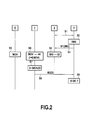
- Figure 2 is a flow diagram of a transaction in the system 1 of Figure 1 , according to a first embodiment of the invention.
- the user U initiates a transaction with the server 3 (step S1). This may involve bi-directional communication between the terminal 2 and the server 3.
- the user U uses another device than the terminal 2 for communication with the server 3, and specifies the how the server 3 can contact the terminal 2.
- the user U uses a personal computer to initiate the transaction with a web server, and specifies his phone number.
- the server 3 determines an image IMG (step S2) and sends a message M1 containing the image IMG to the terminal 2 (step S3).
- the image IMG contains instructions for the user to perform a specific movement MOV. An example of a relation between the instructions contained in the image IMG and the movement MOV will be described hereafter.
- the terminal 2 displays the image IMG on the screen 22 (step S4). Then, the user U performs the movement MOV instructed by the image IMG (step S5) while the sensor 44 measures the movement MOV and the secure element 4 determines data D on the basis of the measured movement MOV (step S6).
- the secure element 2 determines a signature S by signing data D with the cryptographic key K (step S7) and sends a message M2 containing the signature S to the server 3 (step S8).
- the message M2 is first sent from the secure element 2 to a secure device (not shown) and then from the secure device to the server 3. This also applies to the embodiments describes hereafter.
- the server 3 checks whether the signature S corresponds to the image IMG of step S2 (step S9). For example, the server 3 check whether the signature S is a signature by user U of data D' corresponding to the instructions of image IMG. He, data D' represent data that should be determined at step S6 if the user U performs the correct movement. The transaction is validated only if the signature S corresponds to the image IMG of step S2.
- the method of figure 2 allows checking that the transaction is performed under the control of the user U. Indeed, a malware which would run on the terminal 2 would have access to the image IMG, but not to the movement MOV which is measured on the secure element 4 nor to the cryptographic key K which is stored on the secure element 2. Thus, the malware would be incapable of generating a signature S corresponding to the image IMG without knowledge of the user U.
- FIG 3 is a flow diagram of a transaction in the system 1 of Figure 1 , according to a second embodiment of the invention.
- step S11 the user U initiates a transaction with the server 3 (step S11). As in Figure 2 , this may involve bi-directional communication between the terminal 2 and the server 3, or the user U may uses another device than the terminal 2 for communication with the server 3, and specifies the how the server 3 can contact the terminal 2.
- the server 3 determines a challenge CHAL (step S12) and sends a message M3 containing the challenge CHAL to the secure element 4 (step S13).
- the challenge CHAL is for example a number determined in a pseudorandom manner and/or on the basis of transaction data.
- the secure element 4 determines an image IMG (step S14) on the basis of the challenge CHAL.
- the image IMG contains instructions for the user to perform a specific movement MOV.
- the secure element 4 sends a message M4 containing the image IMG to the terminal 2 (step S15).
- the terminal 2 displays the image IMG on the screen 22 (step S16). Then, the user U performs the movement MOV instructed by the image IMG (step S17) while the sensor 44 measures the movement MOV and the secure element 4 determines data D on the basis of the measured movement MOV (step S18).
- the secure element 4 determines whether data D correspond to the movement MOV instructed by the image IMG (step S19). For example, the secure element 4 compares data D with data D' representing data that should be determined at step S18 if the user U performs the correct movement.
- step S19 If it is determined in step S19 that the data D correspond to the movement MOV instructed by the image IMG, the secure element 4 determines a signature S by signing the challenge CHAL with the cryptographic key K (step S20) and sends a message M5 containing the signature S to the server 3 (step S21).
- the server 3 checks whether the signature S corresponds to the challenge CHAL of step S12 (step S22). The transaction is validated only if the signature S corresponds to the challenge CHAL of step S12.
- the method of figure 3 allows checking that the transaction is performed under the control of the user U.
- a malware which would run on the terminal 2 would have access to the image IMG, but not to the movement MOV which is measured on the secure element 4 nor to the cryptographic key K which is stored on the secure element 2, nor to the challenge CHAL which is not transmitted to the terminal 2.
- the malware would be incapable of generating a signature S corresponding to the challenge CHAL without knowledge of the user U.
- step S17 the user U perform a movement MOV1 which correspond to the image IMG, and a movement MOV2 which correspond to his PIN.
- a technique for performing a movement which correspond to a PIN will be described hereafter.
- step S18 both movements MOV1 and MOV2 are measured, data D are determined on the basis of MOV1 and an entered PIN, noted PIN' is determined on the basis of MOV2. Then, data D and PIN' are checked at step S19.
- Figure 4 is a flow diagram of a transaction in the system 1 of Figure 1 , according to a third embodiment of the invention.
- the user U initiates a transaction with the server 3 (step S31).
- the transaction is a payment transaction of an amount A determined by the server 3 (step 32) and involves bi-directional communication between the terminal 2 and the server 3.
- the server 3 sends a message M6 containing the amount A to the secure element 4 (step S33).
- the secure element 4 determines an image IMG (step S34) on the basis of the amount A.
- the image IMG contains instructions for the user to perform a specific movement MOV and the amount A. Then, the secure element 4 sends a message M7 containing the image IMG to the terminal 2 (step S35).
- the terminal 2 In response to the reception of the message M7, the terminal 2 displays the image IMG on the screen 22 (step S36). Then, if the user U agrees with the amount A displayed in the image IMG, he performs the movement MOV instructed by the image IMG (step S37) while the sensor 44 measures the movement MOV and the secure element 4 determines data D on the basis of the measured movement MOV (step S38).
- the secure element 2 determines whether the data D correspond to the movement MOV instructed by the image IMG (step S39).
- step S39 If it is determined in step S39 that data D correspond to the movement MOV instructed by the image IMG, the secure element 4 determines a signature S by signing the amount A with the cryptographic key K (step S40) and sends a message M41 containing the signature S to the server 3 (step S41).
- the message M6 which includes the amount A and the message M8 which include the signature of the amount A may be messages conforming to payment standards, for example to the EMV standards.
- step S42 the server 3 checks whether the signature S corresponds to the amount A of step S32. The transaction is validated only if the signature S corresponds to the amount A of step S32.
- the method of figure 4 allows checking that the transaction is performed under the control of the user U and that the user agrees on the amount A.
- a malware which would run on the terminal 2 would have access to the image IMG, but not to the movement MOV which is measured on the secure element 4 nor to the cryptographic key K which is stored on the secure element 2.
- the malware would be incapable of generating a signature S corresponding to the amount A without knowledge of the user U.
- the malware tries to modify the amount indicated in the displayed image, this would also, by side effect, modify the instruction related to the movement to be performed.
- the movement performed by the user U would not be recognized by the secure element 4 at step S39 and therefore the secure element 4 would not determine the signature S.
- FIG 5 is a flow diagram of a transaction in the system 1 of Figure 1 , according to a fourth embodiment of the invention.
- the user U initiates a transaction with the server 3 (step S51).
- the transaction is a payment transaction of an amount A determined by the server 3 (step S52) and involves bi-directional communication between the terminal 2 and the server 3.
- the server 2 sends a message M9 containing the amount A to the secure element 4 (step S53). Furthermore, the terminal 2 prompts the user to enter the amount A' agreed for the transaction (step S54).
- the user U performs a movement MOV representative of the amount A'.
- the user U uses the terminal 2 which include the secure element 4 as a pen to write the amount A'.
- the amount A' is entered in a similar manner to the entering of a PIN described hereafter.
- the sensor 44 of the secure element 4 measures the movement MOV and the secure element 4 determines an amount A' from the movement MOV measured by the sensor 44 (step S56). Then, the secure element 4 compares the amount A' with the amount A of message M9 (step S57).
- the secure element 4 determines a signature S by signing the amount A with the cryptographic key K (step S58) and sends a message M10 containing the signature S to the server 3 (step S59).
- the message M9 which includes the amount A and the message M10 which include the signature of the amount A may be messages conforming to payment standards, for example to the EMV standards.
- step S60 the server 3 checks whether the signature S corresponds to the amount A of step S52 (step S60). The transaction is validated only if the signature S corresponds to the amount A of step S52.
- the method of figure 5 allows checking that the transaction is performed under the control of the user U and that the user agrees on the amount A. Indeed, a malware which would run on the terminal 2 would not have access to the movement MOV or to the amount A nor to the cryptographic key K. Thus, the malware would be incapable of generating a signature S corresponding to the amount A without knowledge of the user U.
- Figure 6 is a flow diagram of a transaction in the system 1 of Figure 1 , according to a fifth embodiment of the invention.
- the user U initiates a transaction with the server 3 (step S71).
- the transaction is a payment transaction of an amount A.
- the terminal 2 prompts the user to enter the amount A agreed for the transaction (step S72).
- step S73 the user U performs a movement MOV representative of the amount A
- step S74 the sensor 44 of the secure element 4 measures the movement MOV and the secure element 4 determines the amount A from the movement MOV measured by the sensor 44 (step S74).
- step S75 the secure element 4 determines a signature S by signing the amount A with the cryptographic key K (step S75) and sends a message M11 containing the signature S and the amount A to the server 3 (step S76).
- the server 3 checks whether the signature S corresponds to the amount A of message M11 (step S77). The transaction is validated only if the signature S corresponds to the amount A of message M11.
- the method of figure 6 allows checking that the transaction is performed under the control of the user U and that the user agrees on the amount A. Indeed, a malware which would run on the terminal 2 would not have access to the movement MOV or to the amount A nor to the cryptographic key K. Thus, the malware would be incapable of generating a signature S corresponding to the amount A without knowledge of the user U.
- Figure 7 is a flow diagram of a transaction in the system 1 of Figure 1 , according to a sixth embodiment of the invention.
- the secure element 4 controls the execution of functions protected by authentication.
- the secure element 4 is configured for comparing identification or authentication data entered by a user with identification or authentication data stored therein, and authorises the execution of a protected function only if the entered and stored data match.
- the identification or authentication data comprise a PIN.
- a first type of protected function can by authorised by entering the PIN on the user interface 21 of the terminal 2, while a second type of protected function can only be authorised by entering the PIN as described hereafter.
- a protected function of the first type comprises authentication with mobile telephone network
- a protected function of the second type comprises validating a transaction, for example a payment transaction.
- the secure embodiment 4 is in a state ST1 wherein it accepts a PIN entered by the user U on the user interface 21.
- the secure element 4 enters state ST1 (step S90).
- the user U enters his PIN on the keyboard 23 (steps S91 and S92) and the PIN is transmitted to the secure element 4 (step S93), for example in an ADPU command of the ISO 7816 standard.
- the secure element 4 allows authentication with the mobile telephone network (step S94). In other words, authentication with the mobile telephone network is a protected function of the first type mentioned above.
- step S95 the user U initiates a transaction with the server 3 (step S95). This may involve a bi-directional communication between the terminal 2 and the server 3.
- the secure element 4 detects the initiation of the transaction and switches in a state S2 wherein it does not accept a PIN entered on the user interface 21.
- the server 3 sends a message M12 to the secure element 4, containing data T related to the transaction (step S97). For example, in a similar manner to the message M6 of figure 4 , data T contain an amount A.
- the secure element 4 is configured for approving the transaction by signing the data T only if the user U enters his PIN. However, in state ST2, the user cannot transmit his PIN to the secure element 4 by entering it on the user interface 21. In other words, approving the transaction is a protected function of the second type mentioned above.
- step S98 the user U perform a movement MOV corresponding to his PIN.
- the movement MOV is measured by the sensor 44 and the secure element 4 determines an entered PIN, noted PIN', on the basis of the measured movement MOV (step S99).
- The, the secure element 4 determines whether PIN' and the PIN stored in non-volatile memory 42 match (step S100).
- the secure element 4 determines a signature S by signing the data T with the cryptographic key K (step S101) and sends a message M13 containing the signature S to the server 4 (step S102).
- the message M12 which includes data T and the message M13 which includes the signature of the data T may be messages conforming to payment standards, for example to the EMV standards.
- the server 3 checks whether the signature S corresponds to the data T of message M12 (step S103). The transaction is validated only if the signature S corresponds to the data T of message M12.
- the method of figure 7 allows checking that the transaction is performed under the control of the user U and that the user agrees on the data T. Indeed, a malware which would run on the terminal 2 would not have access to data T, the movement MOV or the cryptographic key K. Thus, the malware would be incapable of generating a signature S corresponding to the data T. Furthermore, in case the malware tries to send a PIN from the terminal 2 to the secure element 4, this PIN would not be accepted by the secure element 4 because it would have entered state ST2 upon detection of the beginning of the transaction. Thus, even if a malware intercepts the PIN of the user (for example at step S92), the transaction cannot be validated by the malware without the knowledge of the user. In other words, a protected function of the second type is more secure.
- Figure 8 represents an example of how a user can perform a movement MOV corresponding to instructions displayed in an image IMG (for example at steps S5, S17, S37) to an amount A or A' (for example at steps S55, S73) or to his PIN (for example at steps S37 of the variation mentioned above or step S98) and how the secure element 4 can determines data D, amount A or A' or PIN' (for example at step S6, S18, S38, S56, S74, S99) on the basis of the measured movement.
- the senor 44 is a compass capable of measuring an orientation of the secure element 4 and therefore of the terminal 2.
- the secure element 4 periodically transmits the orientation measured by the sensor 44 to the terminal 2.
- the terminal 2 display an image on the screen 22 comprising a dial 210 and an arrow 211.
- the dial 210 comprises alphanumeric characters, in this example numbers 0 to 9.
- the arrow 211 is displayed at a fixed position while the terminal 2 controls the display of the dial based on the orientation measured by sensor 44.
- the number of the dial 210 indicated by the arrow 211 changes.
- the secure element 4 When the user rotates the terminal 2 so that the arrow 211 indicates a specific number of the dial 210 and stops in this position, the secure element 4 considers that this specific number has been entered. By repeating this, the user can perform a movement MOV comprising a plurality of rotations and stops and which corresponds, for the secure element 4, to a succession of numbers. This succession of numbers represents data determined on the basis of the movement MOV, within the meaning of the present invention.
- the dial 210 is a predetermined image wherein the numbers 0 to 9 are displayed in order.
- the dial 210 may be an image determined by the secure element 4 wherein alphanumeric characters are displayed in a random order. In this case, it is not possible for a malware running on the terminal to determine the data D, amount A/A' or PIN' from the orientation transmitted from the secure element 4 in order to control the display of the dial.
- an image comprise information for instructing the user to perform a specific movement and is displayed by the terminal.
- information for instructing the user to perform the movement is comprised in another type of stimuli, for example a sound or a vibration, which is output by the terminal.
Landscapes
- Engineering & Computer Science (AREA)
- Business, Economics & Management (AREA)
- Theoretical Computer Science (AREA)
- Accounting & Taxation (AREA)
- Physics & Mathematics (AREA)
- General Physics & Mathematics (AREA)
- Strategic Management (AREA)
- General Business, Economics & Management (AREA)
- Finance (AREA)
- General Engineering & Computer Science (AREA)
- Computer Security & Cryptography (AREA)
- Computer Hardware Design (AREA)
- Computer Networks & Wireless Communication (AREA)
- Human Computer Interaction (AREA)
- Development Economics (AREA)
- Economics (AREA)
- Health & Medical Sciences (AREA)
- General Health & Medical Sciences (AREA)
- Social Psychology (AREA)
- Software Systems (AREA)
- Financial Or Insurance-Related Operations Such As Payment And Settlement (AREA)
Abstract
- measuring (56) a movement (MOV) of a first device (4) by a sensor (44) of said first device (4),
- determining the presence of a human being on the basis of the measured movement (MOV).
Description
- The invention relates to the field of transactions involving a communication between the terminal of a user and a server.
- When a transaction is performed between the terminal of a user and a server, it is generally desirable for the server to authenticate the user. Common techniques for authenticating a user are the use of a login and a password, a cryptographic signature calculated by a secure element such as a SIM card, etc.
- Furthermore, considering the possibility that a malicious computer program commonly known as a malware may run on the user's terminal, it is also desirable for the server to verify that the transaction is performed under control of the user.
- A common technique for verifying that a transaction is performed under the control of a user (a human being) is a challenge-response test known as CAPTCHA. Typically, the server sends an image to the terminal which comprises alphanumeric characters that are difficult to recognize for an OCR program, but visible to a human. The terminal displays the image and the user enters the alphanumeric characters. The server checks that the entered characters correspond to the image.
- However, an attack is still possible and indeed, some character recognition software have been developed to recognise the information in a CAPTCHA image.
- Thus, it is desirable to improve the techniques for verifying that a transaction is performed under the control of a user.
- The invention provides a method for determining the presence of a human being, comprising:
- measuring a movement of a first device by a sensor of said first device,
- determining the presence of a human being on the basis of the measured movement.
- In an embodiment, the method comprises outputting a stimuli on a user interface, wherein the stimuli comprises instructions for performing a predetermined movement, wherein determining the presence of a human being on the basis of the measured movement comprises determining the presence of a human being on the basis of the measured movement and of the predetermined movement.
- The method may comprise:
- transmitting the stimuli from a server to said user interface,
- determining, by said first device, a signature on the basis of the measured movement,
- transmitting said signature from the first device to the server.
- The method may comprise:
- transmitting first data from a server to said first device,
- determining, by said first device, said stimuli on the basis of said first data,
- determining, by said first device, whether the measured movement and the predetermined movement match,
- if the measured movement and the predetermined movement match, determining, by said first device, a signature on the basis of the first data,
- transmitting said signature from the first device to the server.
- Said first data may comprise an amount of a payment transaction.
- Said first device may be a secure element.
- Outputting the stimuli on the user interface may comprise outputting the stimuli on the user interface of a second device different from said first device.
- In an embodiment, the method comprises:
- determining transaction data on the basis of the measured movement,
- determining, by said first device, a signature on the basis of said transaction data,
- transmitting said signature from the first device to a server.
- Said transaction data may comprise an amount of a payment transaction.
- In an embodiment, the first device is configured for authorising the execution of a function protected by authentication upon reception of identification or authentication data entered by a user, the method comprising determining said identification or authentication data on the basis of the measured movement.
- The first device may have a first state wherein it accepts identification or authentication data entered on a user interface of a second device and a second state wherein it does not accept identification or authentication data entered on said user interface, the method comprising a step of commuting from said first state to said second state in response to a detection that the second device performs a predetermined transaction.
- The invention also provides a system for determining the presence of a human being, comprising:
- a first device comprising a sensor for measuring a movement of said first device,
- means for determining the presence of a human being on the basis of the measured movement.
- The system may comprise a second device having a user interface for outputting a stimuli, wherein the stimuli comprises instructions for performing a predetermined movement, wherein the means for determining the presence of a human being are configured for determining the presence of a human being on the basis of the measured movement and of the predetermined movement.
- The first device may be a secure element inserted in said second device.
- These and other objects and features of the present invention will become clear from the following description of the preferred embodiments given with reference to the accompanying drawings, in which:
-
Figure 1 shows a system according to an embodiment of the invention, -
Figure 2 is a flow diagram of a transaction in the system ofFigure 1 , according to a first embodiment of the invention, -
Figure 3 is a flow diagram of a transaction in the system ofFigure 1 , according to a second embodiment of the invention, -
Figure 4 is a flow diagram of a transaction in the system ofFigure 1 , according to a third embodiment of the invention, -
Figure 5 is a flow diagram of a transaction in the system ofFigure 1 , according to a fourth embodiment of the invention, -
Figure 6 is a flow diagram of a transaction in the system ofFigure 1 , according to a fifth embodiment of the invention, -
Figure 7 is a flow diagram of a transaction in the system ofFigure 1 , according to a sixth embodiment of the invention, and -
Figure 8 illustrate a method for entering a PIN in the system offigure 1 . -
Figure 1 shows asystem 1 which comprises aterminal 2, aserver 3, and asecure element 4. In an example embodiment, theterminal 2 is the mobile phone of a user (a human being), theserver 3 is a point-of-sale payment terminal and thesecure element 2 is a smart card inserted in the terminal, for example a SIM card. However, the invention is not limited to this embodiment. For example, theterminal 2 may be a personal computer, a portable electronic device, etc. Theserver 3 may be an ATM or a web server. Thesecure element 4 may be a USB key connected toterminal 2 or a separate device which communicates with theterminal 2 by a wireless or wire connection. Also, theterminal 2 and theserver 3 may be the same device. - The
terminal 2 presents the general architecture of a computer. It comprises auser interface 21 which include for example ascreen 22 and akeyboard 23 or a touchscreen, aprocessor 24, anon-volatile memory 25, avolatile memory 26, acommunication interface 27 and acommunication interface 28. Theprocessor 24 allows executing computer programs stored innon-volatile memory 25, by usingvolatile memory 26. The functioning of theterminal 2 described hereafter corresponds to the execution of such computer programs. - The
communication interface 27 allows communication between theterminal 2 and theserver 3 through a link L1. For example,communication interface 27 is a short range radio communication interface, for example a Near Field Communication (NFC) interface which includes a Frontend NFC and a NFC antenna. In other embodiments, thecommunication interface 27 is configured for communication with theserver 3 through a wire or wireless network, for example through the Internet and/or through a mobile phone network. - The
communication interface 28 allows communication between the terminal 2 and thesecure element 4 through a link L2. In the example of a smart card inserted in theterminal 3, the link L2 is for example a standardised ISO 7816 link. - The
secure element 4 presents the general architecture of a computer. It comprises aprocessor 41, anon-volatile memory 42, avolatile memory 43, asensor 44 and acommunication interface 45. Theprocessor 41 allows executing computer programs stored innon-volatile memory 42, by usingvolatile memory 43. The functioning of thesecure element 4 described hereafter corresponds to the execution of such computer programs. Thecommunication interface 45 allows communication between the terminal 2 and thesecure element 4 through link L2. Thenon-volatile memory 42 stores a PIN code and a cryptographic key K of the user. Thesensor 44 is for example a MEMS sensor, an accelerometer, a compass, etc. configured for measuring a movement, an orientation or a position of thesecure element 2. - Links L1 and L2 allow communication between the
secure element 4 and theserver 2 through a link L3, which is based for example on SWP protocols and which enables communication between an NFC frontend and thesecure element 4. - The
server 3 presents the general architecture of a computer. It comprises aprocessor 31, anon-volatile memory 32, avolatile memory 33 and acommunication interface 34. Theprocessor 31 allows executing computer programs stored innon-volatile memory 32, by usingvolatile memory 33. The functioning of theserver 3 described hereafter corresponds to the execution of such computer programs. Thecommunication interface 34 allows communication between the terminal 2 and theserver 3 through link L1. - In the system of
figure 1 , thesecure element 4 is considered a more secure environment than theterminal 2. Indeed, installing new applications by loading computer programs in thenon-volatile memory 25 of theterminal 2 is a usual task which can be performed by the user of theterminal 2. Installing of a new application in theterminal 2 may involve, without knowledge of the user, the installation of a malware. Thus, a malware may by running on theterminal 2. In contrast, loading a computer program in thenon-volatile memory 42 of thesecure element 4 can only be performed after authentication by an authorised party, for example the manufacturer or the issuer of the secure element or a trusted third party. In other words, thesecure element 4 comprises means for authorising the loading of a computer program in itsnon-volatile memory 42 only after authentication by an authorised party. Thus, normally there is no malware running on thesecure element 4. -
Figure 2 is a flow diagram of a transaction in thesystem 1 ofFigure 1 , according to a first embodiment of the invention. - Initially, the user U initiates a transaction with the server 3 (step S1). This may involve bi-directional communication between the terminal 2 and the
server 3. In another embodiment, the user U uses another device than theterminal 2 for communication with theserver 3, and specifies the how theserver 3 can contact theterminal 2. For example, the user U uses a personal computer to initiate the transaction with a web server, and specifies his phone number. - Then, when the transaction needs to be validated by confirming that it is performed under the control of the user U, the
server 3 determines an image IMG (step S2) and sends a message M1 containing the image IMG to the terminal 2 (step S3). The image IMG contains instructions for the user to perform a specific movement MOV. An example of a relation between the instructions contained in the image IMG and the movement MOV will be described hereafter. - In response to the reception of the message M1, the
terminal 2 displays the image IMG on the screen 22 (step S4). Then, the user U performs the movement MOV instructed by the image IMG (step S5) while thesensor 44 measures the movement MOV and thesecure element 4 determines data D on the basis of the measured movement MOV (step S6). - Then, the
secure element 2 determines a signature S by signing data D with the cryptographic key K (step S7) and sends a message M2 containing the signature S to the server 3 (step S8). In an alternative, the message M2 is first sent from thesecure element 2 to a secure device (not shown) and then from the secure device to theserver 3. This also applies to the embodiments describes hereafter. - Finally, the
server 3 checks whether the signature S corresponds to the image IMG of step S2 (step S9). For example, theserver 3 check whether the signature S is a signature by user U of data D' corresponding to the instructions of image IMG. He, data D' represent data that should be determined at step S6 if the user U performs the correct movement. The transaction is validated only if the signature S corresponds to the image IMG of step S2. - The method of
figure 2 allows checking that the transaction is performed under the control of the user U. Indeed, a malware which would run on theterminal 2 would have access to the image IMG, but not to the movement MOV which is measured on thesecure element 4 nor to the cryptographic key K which is stored on thesecure element 2. Thus, the malware would be incapable of generating a signature S corresponding to the image IMG without knowledge of the user U. -
Figure 3 is a flow diagram of a transaction in thesystem 1 ofFigure 1 , according to a second embodiment of the invention. - Initially, the user U initiates a transaction with the server 3 (step S11). As in
Figure 2 , this may involve bi-directional communication between the terminal 2 and theserver 3, or the user U may uses another device than theterminal 2 for communication with theserver 3, and specifies the how theserver 3 can contact theterminal 2. - Then, when the transaction needs to be validated by confirming that it is performed under the control of the user U, the
server 3 determines a challenge CHAL (step S12) and sends a message M3 containing the challenge CHAL to the secure element 4 (step S13). The challenge CHAL is for example a number determined in a pseudorandom manner and/or on the basis of transaction data. - In response to the reception of the message M3, the
secure element 4 determines an image IMG (step S14) on the basis of the challenge CHAL. As inFigure 2 , the image IMG contains instructions for the user to perform a specific movement MOV. Then, thesecure element 4 sends a message M4 containing the image IMG to the terminal 2 (step S15). - In response to the reception of the message M4, the
terminal 2 displays the image IMG on the screen 22 (step S16). Then, the user U performs the movement MOV instructed by the image IMG (step S17) while thesensor 44 measures the movement MOV and thesecure element 4 determines data D on the basis of the measured movement MOV (step S18). - Then, the
secure element 4 determines whether data D correspond to the movement MOV instructed by the image IMG (step S19). For example, thesecure element 4 compares data D with data D' representing data that should be determined at step S18 if the user U performs the correct movement. - If it is determined in step S19 that the data D correspond to the movement MOV instructed by the image IMG, the
secure element 4 determines a signature S by signing the challenge CHAL with the cryptographic key K (step S20) and sends a message M5 containing the signature S to the server 3 (step S21). - Finally, the
server 3 checks whether the signature S corresponds to the challenge CHAL of step S12 (step S22). The transaction is validated only if the signature S corresponds to the challenge CHAL of step S12. - The method of
figure 3 allows checking that the transaction is performed under the control of the user U. Indeed, a malware which would run on theterminal 2 would have access to the image IMG, but not to the movement MOV which is measured on thesecure element 4 nor to the cryptographic key K which is stored on thesecure element 2, nor to the challenge CHAL which is not transmitted to theterminal 2. Thus, the malware would be incapable of generating a signature S corresponding to the challenge CHAL without knowledge of the user U. - In a variation of the method of
Figure 3 , at step S17, the user U perform a movement MOV1 which correspond to the image IMG, and a movement MOV2 which correspond to his PIN. A technique for performing a movement which correspond to a PIN will be described hereafter. At step S18, both movements MOV1 and MOV2 are measured, data D are determined on the basis of MOV1 and an entered PIN, noted PIN' is determined on the basis of MOV2. Then, data D and PIN' are checked at step S19. -
Figure 4 is a flow diagram of a transaction in thesystem 1 ofFigure 1 , according to a third embodiment of the invention. - Initially, the user U initiates a transaction with the server 3 (step S31). In this example, the transaction is a payment transaction of an amount A determined by the server 3 (step 32) and involves bi-directional communication between the terminal 2 and the
server 3. - Then, when the transaction needs to be validated by confirming that it is performed under the control of the user U, the
server 3 sends a message M6 containing the amount A to the secure element 4 (step S33). - In response to the reception of the message M6, the
secure element 4 determines an image IMG (step S34) on the basis of the amount A. The image IMG contains instructions for the user to perform a specific movement MOV and the amount A. Then, thesecure element 4 sends a message M7 containing the image IMG to the terminal 2 (step S35). - In response to the reception of the message M7, the
terminal 2 displays the image IMG on the screen 22 (step S36). Then, if the user U agrees with the amount A displayed in the image IMG, he performs the movement MOV instructed by the image IMG (step S37) while thesensor 44 measures the movement MOV and thesecure element 4 determines data D on the basis of the measured movement MOV (step S38). - Then, the
secure element 2 determines whether the data D correspond to the movement MOV instructed by the image IMG (step S39). - If it is determined in step S39 that data D correspond to the movement MOV instructed by the image IMG, the
secure element 4 determines a signature S by signing the amount A with the cryptographic key K (step S40) and sends a message M41 containing the signature S to the server 3 (step S41). - Here, the message M6 which includes the amount A and the message M8 which include the signature of the amount A may be messages conforming to payment standards, for example to the EMV standards.
- Finally, the
server 3 checks whether the signature S corresponds to the amount A of step S32 (step S42). The transaction is validated only if the signature S corresponds to the amount A of step S32. - The method of
figure 4 allows checking that the transaction is performed under the control of the user U and that the user agrees on the amount A. Indeed, a malware which would run on theterminal 2 would have access to the image IMG, but not to the movement MOV which is measured on thesecure element 4 nor to the cryptographic key K which is stored on thesecure element 2. Thus, the malware would be incapable of generating a signature S corresponding to the amount A without knowledge of the user U. Furthermore, in case the malware tries to modify the amount indicated in the displayed image, this would also, by side effect, modify the instruction related to the movement to be performed. The movement performed by the user U would not be recognized by thesecure element 4 at step S39 and therefore thesecure element 4 would not determine the signature S. -
Figure 5 is a flow diagram of a transaction in thesystem 1 ofFigure 1 , according to a fourth embodiment of the invention. - Initially, the user U initiates a transaction with the server 3 (step S51). In this example, the transaction is a payment transaction of an amount A determined by the server 3 (step S52) and involves bi-directional communication between the terminal 2 and the
server 3. - Then, when the transaction needs to be validated by confirming that it is performed under the control of the user U, the
server 2 sends a message M9 containing the amount A to the secure element 4 (step S53). Furthermore, theterminal 2 prompts the user to enter the amount A' agreed for the transaction (step S54). - Thus in response to step S54, the user U performs a movement MOV representative of the amount A'. For example, the user U uses the
terminal 2 which include thesecure element 4 as a pen to write the amount A'. In a variation, the amount A' is entered in a similar manner to the entering of a PIN described hereafter. Meanwhile, thesensor 44 of thesecure element 4 measures the movement MOV and thesecure element 4 determines an amount A' from the movement MOV measured by the sensor 44 (step S56). Then, thesecure element 4 compares the amount A' with the amount A of message M9 (step S57). - If A' = A, the
secure element 4 determines a signature S by signing the amount A with the cryptographic key K (step S58) and sends a message M10 containing the signature S to the server 3 (step S59). - Here, the message M9 which includes the amount A and the message M10 which include the signature of the amount A may be messages conforming to payment standards, for example to the EMV standards.
- Finally, the
server 3 checks whether the signature S corresponds to the amount A of step S52 (step S60). The transaction is validated only if the signature S corresponds to the amount A of step S52. - The method of
figure 5 allows checking that the transaction is performed under the control of the user U and that the user agrees on the amount A. Indeed, a malware which would run on theterminal 2 would not have access to the movement MOV or to the amount A nor to the cryptographic key K. Thus, the malware would be incapable of generating a signature S corresponding to the amount A without knowledge of the user U. -
Figure 6 is a flow diagram of a transaction in thesystem 1 ofFigure 1 , according to a fifth embodiment of the invention. - Initially, the user U initiates a transaction with the server 3 (step S71). In this example, the transaction is a payment transaction of an amount A.
- Then, the
terminal 2 prompts the user to enter the amount A agreed for the transaction (step S72). - Thus in response to step S72, the user U performs a movement MOV representative of the amount A (step S73). Meanwhile, the
sensor 44 of thesecure element 4 measures the movement MOV and thesecure element 4 determines the amount A from the movement MOV measured by the sensor 44 (step S74). Then, thesecure element 4 determines a signature S by signing the amount A with the cryptographic key K (step S75) and sends a message M11 containing the signature S and the amount A to the server 3 (step S76). - Finally, the
server 3 checks whether the signature S corresponds to the amount A of message M11 (step S77). The transaction is validated only if the signature S corresponds to the amount A of message M11. - The method of
figure 6 allows checking that the transaction is performed under the control of the user U and that the user agrees on the amount A. Indeed, a malware which would run on theterminal 2 would not have access to the movement MOV or to the amount A nor to the cryptographic key K. Thus, the malware would be incapable of generating a signature S corresponding to the amount A without knowledge of the user U. -
Figure 7 is a flow diagram of a transaction in thesystem 1 ofFigure 1 , according to a sixth embodiment of the invention. - In this embodiment, the
secure element 4 controls the execution of functions protected by authentication. Thesecure element 4 is configured for comparing identification or authentication data entered by a user with identification or authentication data stored therein, and authorises the execution of a protected function only if the entered and stored data match. In this example, the identification or authentication data comprise a PIN. Furthermore, a first type of protected function can by authorised by entering the PIN on theuser interface 21 of theterminal 2, while a second type of protected function can only be authorised by entering the PIN as described hereafter. In this example, a protected function of the first type comprises authentication with mobile telephone network, and a protected function of the second type comprises validating a transaction, for example a payment transaction. - Initially, the
secure embodiment 4 is in a state ST1 wherein it accepts a PIN entered by the user U on theuser interface 21. For example, when theterminal 2 is turned on, thesecure element 4 enters state ST1 (step S90). Then, the user U enters his PIN on the keyboard 23 (steps S91 and S92) and the PIN is transmitted to the secure element 4 (step S93), for example in an ADPU command of the ISO 7816 standard. If the transmitted PIN matches the PIN stored innon-volatile memory 42, thesecure element 4 allows authentication with the mobile telephone network (step S94). In other words, authentication with the mobile telephone network is a protected function of the first type mentioned above. - Later, the user U initiates a transaction with the server 3 (step S95). This may involve a bi-directional communication between the terminal 2 and the
server 3. - At step S96, the
secure element 4 detects the initiation of the transaction and switches in a state S2 wherein it does not accept a PIN entered on theuser interface 21. - Then, the
server 3 sends a message M12 to thesecure element 4, containing data T related to the transaction (step S97). For example, in a similar manner to the message M6 offigure 4 , data T contain an amount A. - The
secure element 4 is configured for approving the transaction by signing the data T only if the user U enters his PIN. However, in state ST2, the user cannot transmit his PIN to thesecure element 4 by entering it on theuser interface 21. In other words, approving the transaction is a protected function of the second type mentioned above. - Thus, in step S98, the user U perform a movement MOV corresponding to his PIN. The movement MOV is measured by the
sensor 44 and thesecure element 4 determines an entered PIN, noted PIN', on the basis of the measured movement MOV (step S99). The, thesecure element 4 determines whether PIN' and the PIN stored innon-volatile memory 42 match (step S100). - In case the PINs matches, the
secure element 4 determines a signature S by signing the data T with the cryptographic key K (step S101) and sends a message M13 containing the signature S to the server 4 (step S102). - Here, the message M12 which includes data T and the message M13 which includes the signature of the data T may be messages conforming to payment standards, for example to the EMV standards.
- Finally, the
server 3 checks whether the signature S corresponds to the data T of message M12 (step S103). The transaction is validated only if the signature S corresponds to the data T of message M12. - The method of
figure 7 allows checking that the transaction is performed under the control of the user U and that the user agrees on the data T. Indeed, a malware which would run on theterminal 2 would not have access to data T, the movement MOV or the cryptographic key K. Thus, the malware would be incapable of generating a signature S corresponding to the data T. Furthermore, in case the malware tries to send a PIN from theterminal 2 to thesecure element 4, this PIN would not be accepted by thesecure element 4 because it would have entered state ST2 upon detection of the beginning of the transaction. Thus, even if a malware intercepts the PIN of the user (for example at step S92), the transaction cannot be validated by the malware without the knowledge of the user. In other words, a protected function of the second type is more secure. -
Figure 8 represents an example of how a user can perform a movement MOV corresponding to instructions displayed in an image IMG (for example at steps S5, S17, S37) to an amount A or A' (for example at steps S55, S73) or to his PIN (for example at steps S37 of the variation mentioned above or step S98) and how thesecure element 4 can determines data D, amount A or A' or PIN' (for example at step S6, S18, S38, S56, S74, S99) on the basis of the measured movement. - In this example, the
sensor 44 is a compass capable of measuring an orientation of thesecure element 4 and therefore of theterminal 2. Thesecure element 4 periodically transmits the orientation measured by thesensor 44 to theterminal 2. - The
terminal 2 display an image on thescreen 22 comprising adial 210 and anarrow 211. Thedial 210 comprises alphanumeric characters, in this example numbers 0 to 9. Thearrow 211 is displayed at a fixed position while theterminal 2 controls the display of the dial based on the orientation measured bysensor 44. Thus, as show infigure 8 , when the user performs a movement which changes the orientation of theterminal 2, the number of thedial 210 indicated by thearrow 211 changes. - When the user rotates the
terminal 2 so that thearrow 211 indicates a specific number of thedial 210 and stops in this position, thesecure element 4 considers that this specific number has been entered. By repeating this, the user can perform a movement MOV comprising a plurality of rotations and stops and which corresponds, for thesecure element 4, to a succession of numbers. This succession of numbers represents data determined on the basis of the movement MOV, within the meaning of the present invention. - In the example of
figure 8 , thedial 210 is a predetermined image wherein thenumbers 0 to 9 are displayed in order. However, thedial 210 may be an image determined by thesecure element 4 wherein alphanumeric characters are displayed in a random order. In this case, it is not possible for a malware running on the terminal to determine the data D, amount A/A' or PIN' from the orientation transmitted from thesecure element 4 in order to control the display of the dial. - In some of the embodiment above, an image comprise information for instructing the user to perform a specific movement and is displayed by the terminal. In a variation, information for instructing the user to perform the movement is comprised in another type of stimuli, for example a sound or a vibration, which is output by the terminal.
Claims (15)
- A system (1) for determining the presence of a human being, comprising:- a first device (4) comprising a sensor (44) for measuring (S6, S18, S38, S56, S74, S99) a movement (MOV) of said first device (4),- means for determining the presence of a human being on the basis of the measured movement (MOV).
- A system according to claim 2, comprising a second device (2) having a user interface (21) for outputting a stimuli, wherein the stimuli comprises instructions for performing a predetermined movement, wherein the means for determining the presence of a human being are configured for determining the presence of a human being on the basis of the measured movement and of the predetermined movement.
- A system according to claim 2, comprising a server (3) comprising means for transmitting (S3) the stimuli from the server (3) to said user interface (21), wherein the first device (4) comprises:- means for determining (S7) a signature (S) on the basis of the measured movement,- means for transmitting (S8) said signature (S) from the first device (4) to a secure device or to the server (3).
- A system according to claim 2, comprising a server (3) comprising means for transmitting (S13, S33) first data (CHAL, A) from the server (3) to said first device (4), wherein the first device (4) comprises:- means for determining (S14, S34) said stimuli (IMG) on the basis of said first data (CHAL, A),- means determining (S19, S39) whether the measured movement and the predetermined movement match,- means for determining (S20, S40), if the measured movement and the predetermined movement match, a signature (S) on the basis of the first data (CHAL, A),- means for transmitting (S21, S41) said signature (S) from the first device (4) to a secure device or to the server (3).
- A system according to claim 4, wherein said first data comprise an amount (A) of a payment transaction.
- A system according to one of claims 2 to 5, wherein said first device (4) is a secure element.
- A system according to claim 6, wherein the second device (2) is different from said first device (4).
- A system according to claim 1 comprising means for determining (S56, S74) transaction data (A, A') on the basis of the measured movement, wherein the first device (4) comprises:- means for determining (S58, S75) a signature (S) on the basis of said transaction data (A, A'),- means for transmitting (S59, S76) said signature (S) from the first device (4) to a secure device or to a server (3).
- A system according to claim 6, wherein said transaction data comprise an amount (A) of a payment transaction.
- A system according to one of claims 8 to 9, wherein said first device (4) is a secure element.
- A system according to claim 1, wherein the first device (4) is configured for authorising the execution of a function protected by authentication upon reception of identification or authentication data entered by a user, the system comprising means for determining (S99) said identification or authentication data on the basis of the measured movement.
- A system according to claim 11, wherein the first device (4) has a first state (ST1) wherein it accepts identification or authentication data entered on a user interface (21) of a second device (2) and a second state (ST2) wherein it does not accept identification or authentication data entered on said user interface (21), the system comprising means for commuting from said first state (ST1) to said second state (ST2) in response to a detection (S96) that the second device (2) performs a predetermined transaction.
- A system according to claim 12, wherein said first device (4) is a secure element.
- A method for determining the presence of a human being, comprising:- measuring (S6, S18, S38, S56, S74, S99) a movement (MOV) of a first device (4) by a sensor (44) of said first device (4),- determining the presence of a human being on the basis of the measured movement (MOV).
- A method according to claim 14, comprising:- outputting (S4, S16, S36) a stimuli (IMG) on a user interface (21), wherein the stimuli comprises instructions for performing a predetermined movement,
wherein determining the presence of a human being on the basis of the measured movement comprises determining the presence of a human being on the basis of the measured movement and of the predetermined movement.
Applications Claiming Priority (1)
| Application Number | Priority Date | Filing Date | Title |
|---|---|---|---|
| FR1251593A FR2987152B1 (en) | 2012-02-22 | 2012-02-22 | METHOD AND SECURITY DEVICE FOR PERFORMING A TRANSACTION |
Publications (1)
| Publication Number | Publication Date |
|---|---|
| EP2631834A1 true EP2631834A1 (en) | 2013-08-28 |
Family
ID=47720438
Family Applications (1)
| Application Number | Title | Priority Date | Filing Date |
|---|---|---|---|
| EP13156213.4A Ceased EP2631834A1 (en) | 2012-02-22 | 2013-02-21 | Method and secure device for performing a transaction |
Country Status (3)
| Country | Link |
|---|---|
| US (1) | US10528943B2 (en) |
| EP (1) | EP2631834A1 (en) |
| FR (1) | FR2987152B1 (en) |
Cited By (6)
| Publication number | Priority date | Publication date | Assignee | Title |
|---|---|---|---|---|
| EP2881880A1 (en) * | 2013-12-06 | 2015-06-10 | Bundesdruckerei GmbH | Method for verifying whether an electronic service query for carrying out an electronic service comes from a person or an automated apparatus |
| EP2908225A1 (en) * | 2014-02-17 | 2015-08-19 | Noodoe Corporation | Methods and systems for connecting a process based on motion detection |
| CN104951067A (en) * | 2014-03-25 | 2015-09-30 | 拓连科技股份有限公司 | Action management method and system of electronic device |
| WO2015164046A1 (en) * | 2014-04-21 | 2015-10-29 | Alibaba Group Holding Limited | Verification method and device using a magnetometer |
| EP3026522A1 (en) * | 2014-11-26 | 2016-06-01 | Nokia Technologies OY | User interface |
| WO2018034880A1 (en) * | 2016-08-18 | 2018-02-22 | Mastercard International Incorporated | Systems and methods for use in authenticating consumers in connection with payment account transactions |
Families Citing this family (2)
| Publication number | Priority date | Publication date | Assignee | Title |
|---|---|---|---|---|
| JP6540195B2 (en) * | 2014-08-05 | 2019-07-10 | セイコーエプソン株式会社 | Accounting system and information processing method |
| JP6650543B1 (en) * | 2019-03-25 | 2020-02-19 | さくら情報システム株式会社 | Information processing apparatus, method and program |
Citations (5)
| Publication number | Priority date | Publication date | Assignee | Title |
|---|---|---|---|---|
| KR20060135340A (en) * | 2005-06-24 | 2006-12-29 | 주식회사 팬택 | Electronic payment signature method and system using acceleration sensor provided in mobile communication terminal |
| KR20070045765A (en) * | 2005-10-28 | 2007-05-02 | 엘지전자 주식회사 | Mobile communication terminal with user authentication function by motion detection and its method |
| US20110117839A1 (en) * | 2008-06-02 | 2011-05-19 | Gemalto Sa | Method for application selection in a wireless mobile communication device in an nfc system and a corresponding wireless mobile communication device |
| WO2011066381A2 (en) * | 2009-11-25 | 2011-06-03 | Visa International Service Association | Transaction using a mobile device with an accelerometer |
| US8255323B1 (en) * | 2009-01-09 | 2012-08-28 | Apple Inc. | Motion based payment confirmation |
Family Cites Families (12)
| Publication number | Priority date | Publication date | Assignee | Title |
|---|---|---|---|---|
| US6397130B1 (en) * | 2000-04-13 | 2002-05-28 | Ensco, Ltd. | Multi-sensor route detector for rail vehicle navigation |
| RU2428808C2 (en) * | 2007-01-26 | 2011-09-10 | Интердиджитал Текнолоджи Корпорейшн | Method and device to arrange protection of location information and to control access with application of location information |
| US8028896B2 (en) * | 2007-12-14 | 2011-10-04 | Bank Of America Corporation | Authentication methods for use in financial transactions and information banking |
| EP2320355A1 (en) * | 2009-11-04 | 2011-05-11 | BRITISH TELECOMMUNICATIONS public limited company | Monitoring movement |
| US8433914B1 (en) * | 2010-02-25 | 2013-04-30 | Emc Corporation | Multi-channel transaction signing |
| US9077912B2 (en) * | 2010-09-23 | 2015-07-07 | Intel Corporation | Motion initiated time synchronization |
| US8560839B2 (en) * | 2010-12-20 | 2013-10-15 | Microsoft Corporation | Tamper proof location services |
| US10692081B2 (en) * | 2010-12-31 | 2020-06-23 | Mastercard International Incorporated | Local management of payment transactions |
| US20130046635A1 (en) * | 2011-08-19 | 2013-02-21 | Bank Of America Corporation | Triggering offers based on detected location of a mobile point of sale device |
| US8639928B2 (en) * | 2011-12-05 | 2014-01-28 | Certicom Corp. | System and method for mounting encrypted data based on availability of a key on a network |
| US20130142384A1 (en) * | 2011-12-06 | 2013-06-06 | Microsoft Corporation | Enhanced navigation through multi-sensor positioning |
| US9582826B2 (en) * | 2012-01-23 | 2017-02-28 | Bank Of America Corporation | Directional wayfinding |
-
2012
- 2012-02-22 FR FR1251593A patent/FR2987152B1/en active Active
-
2013
- 2013-02-21 EP EP13156213.4A patent/EP2631834A1/en not_active Ceased
- 2013-02-21 US US13/773,298 patent/US10528943B2/en active Active
Patent Citations (5)
| Publication number | Priority date | Publication date | Assignee | Title |
|---|---|---|---|---|
| KR20060135340A (en) * | 2005-06-24 | 2006-12-29 | 주식회사 팬택 | Electronic payment signature method and system using acceleration sensor provided in mobile communication terminal |
| KR20070045765A (en) * | 2005-10-28 | 2007-05-02 | 엘지전자 주식회사 | Mobile communication terminal with user authentication function by motion detection and its method |
| US20110117839A1 (en) * | 2008-06-02 | 2011-05-19 | Gemalto Sa | Method for application selection in a wireless mobile communication device in an nfc system and a corresponding wireless mobile communication device |
| US8255323B1 (en) * | 2009-01-09 | 2012-08-28 | Apple Inc. | Motion based payment confirmation |
| WO2011066381A2 (en) * | 2009-11-25 | 2011-06-03 | Visa International Service Association | Transaction using a mobile device with an accelerometer |
Cited By (13)
| Publication number | Priority date | Publication date | Assignee | Title |
|---|---|---|---|---|
| EP2881880A1 (en) * | 2013-12-06 | 2015-06-10 | Bundesdruckerei GmbH | Method for verifying whether an electronic service query for carrying out an electronic service comes from a person or an automated apparatus |
| EP2908225A1 (en) * | 2014-02-17 | 2015-08-19 | Noodoe Corporation | Methods and systems for connecting a process based on motion detection |
| US9557820B2 (en) | 2014-02-17 | 2017-01-31 | Noodoe Corporation | Methods and systems for commencing a process based on motion detection |
| EP2924544A1 (en) * | 2014-03-25 | 2015-09-30 | Noodoe Corporation | Methods and systems for managing motion information for electronic devices |
| CN104951067A (en) * | 2014-03-25 | 2015-09-30 | 拓连科技股份有限公司 | Action management method and system of electronic device |
| CN104951067B (en) * | 2014-03-25 | 2018-09-25 | 拓连科技股份有限公司 | Action management method and system of electronic device |
| WO2015164046A1 (en) * | 2014-04-21 | 2015-10-29 | Alibaba Group Holding Limited | Verification method and device using a magnetometer |
| US9877189B2 (en) | 2014-04-21 | 2018-01-23 | Alibaba Group Holding Limited | Verification method and device using a magnetometer |
| US10206105B2 (en) | 2014-04-21 | 2019-02-12 | Alibaba Group Holding Limited | Verification method and device using a magnetometer |
| EP3026522A1 (en) * | 2014-11-26 | 2016-06-01 | Nokia Technologies OY | User interface |
| WO2018034880A1 (en) * | 2016-08-18 | 2018-02-22 | Mastercard International Incorporated | Systems and methods for use in authenticating consumers in connection with payment account transactions |
| US10846697B2 (en) | 2016-08-18 | 2020-11-24 | Mastercard International Incorporated | Systems and methods for use in authenticating consumers in connection with payment account transactions |
| US11710127B2 (en) | 2016-08-18 | 2023-07-25 | Mastercard International Incorporated | Systems and methods for use in authenticating consumers in connection with payment account transactions |
Also Published As
| Publication number | Publication date |
|---|---|
| US20130218775A1 (en) | 2013-08-22 |
| FR2987152A1 (en) | 2013-08-23 |
| FR2987152B1 (en) | 2017-11-17 |
| US10528943B2 (en) | 2020-01-07 |
Similar Documents
| Publication | Publication Date | Title |
|---|---|---|
| US10528943B2 (en) | Method and secure device for performing a transaction | |
| EP2559012B1 (en) | System for secure payment over a wireless communication network | |
| RU2523304C2 (en) | Trusted integrity manager (tim) | |
| US9002739B2 (en) | Method and system for signature capture | |
| RU2537795C2 (en) | Trusted remote attestation agent (traa) | |
| US20150095222A1 (en) | Dynamic identity representation in mobile devices | |
| KR101804182B1 (en) | Online financial transactions, identity authentication system and method using real cards | |
| KR101607935B1 (en) | System for paying mobile using finger scan and method therefor | |
| JP2010515321A (en) | Method and system for enhancing the security of electronic signature generation with a chip card | |
| WO2017104288A1 (en) | Settlement system, user terminal and method executed therein, settlement device and method executed therein, and program | |
| KR20110002968A (en) | Method and system for providing financial transaction service using biometric authentication and portable storage device therefor | |
| US20230291724A1 (en) | Method and system for authenticating a user in a session initiated on a computing device | |
| CN101069154A (en) | Non-intrusive trust user interface | |
| US20080189762A1 (en) | Authentication apparatus and authentication method | |
| CN104753940B (en) | A kind of method to issue invoice, common invoice self-service terminal and server | |
| EP1729236A2 (en) | Communication terminal device and computer device | |
| US20190279213A1 (en) | Method for processing transaction data, corresponding communications terminal, card reader and program | |
| KR20110002967A (en) | Method and system for providing real name authentication service using biometric authentication and portable storage device therefor | |
| KR102745613B1 (en) | End-to-end secure pairing of secure elements and mobile devices | |
| EP1486908A1 (en) | Smart card with two I/O ports for linking secure and insecure environments | |
| KR20190052405A (en) | Computer security system and method using authentication function in smart phone | |
| TWI646481B (en) | Pairing authentication method for electronic transaction device | |
| EP4405780B1 (en) | Icc reader | |
| JP7563658B1 (en) | Ticket verification device, information processing method, and program | |
| KR20150114358A (en) | User authentication system by contacting card and operating method thereof |
Legal Events
| Date | Code | Title | Description |
|---|---|---|---|
| PUAI | Public reference made under article 153(3) epc to a published international application that has entered the european phase |
Free format text: ORIGINAL CODE: 0009012 |
|
| AK | Designated contracting states |
Kind code of ref document: A1 Designated state(s): AL AT BE BG CH CY CZ DE DK EE ES FI FR GB GR HR HU IE IS IT LI LT LU LV MC MK MT NL NO PL PT RO RS SE SI SK SM TR |
|
| AX | Request for extension of the european patent |
Extension state: BA ME |
|
| 17P | Request for examination filed |
Effective date: 20140214 |
|
| RBV | Designated contracting states (corrected) |
Designated state(s): AL AT BE BG CH CY CZ DE DK EE ES FI FR GB GR HR HU IE IS IT LI LT LU LV MC MK MT NL NO PL PT RO RS SE SI SK SM TR |
|
| 17Q | First examination report despatched |
Effective date: 20150409 |
|
| RAP1 | Party data changed (applicant data changed or rights of an application transferred) |
Owner name: IDEMIA FRANCE |
|
| STAA | Information on the status of an ep patent application or granted ep patent |
Free format text: STATUS: THE APPLICATION HAS BEEN REFUSED |
|
| 18R | Application refused |
Effective date: 20180704 |