EP2631735A2 - Keyboard device, keyboard holding device and information input device - Google Patents
Keyboard device, keyboard holding device and information input device Download PDFInfo
- Publication number
- EP2631735A2 EP2631735A2 EP12190880.0A EP12190880A EP2631735A2 EP 2631735 A2 EP2631735 A2 EP 2631735A2 EP 12190880 A EP12190880 A EP 12190880A EP 2631735 A2 EP2631735 A2 EP 2631735A2
- Authority
- EP
- European Patent Office
- Prior art keywords
- keyboard
- parts
- face
- unit
- engaging
- Prior art date
- Legal status (The legal status is an assumption and is not a legal conclusion. Google has not performed a legal analysis and makes no representation as to the accuracy of the status listed.)
- Granted
Links
Images






Classifications
-
- G—PHYSICS
- G06—COMPUTING OR CALCULATING; COUNTING
- G06F—ELECTRIC DIGITAL DATA PROCESSING
- G06F1/00—Details not covered by groups G06F3/00 - G06F13/00 and G06F21/00
- G06F1/16—Constructional details or arrangements
-
- G—PHYSICS
- G06—COMPUTING OR CALCULATING; COUNTING
- G06F—ELECTRIC DIGITAL DATA PROCESSING
- G06F1/00—Details not covered by groups G06F3/00 - G06F13/00 and G06F21/00
- G06F1/16—Constructional details or arrangements
- G06F1/1613—Constructional details or arrangements for portable computers
- G06F1/1633—Constructional details or arrangements of portable computers not specific to the type of enclosures covered by groups G06F1/1615 - G06F1/1626
- G06F1/1662—Details related to the integrated keyboard
-
- G—PHYSICS
- G06—COMPUTING OR CALCULATING; COUNTING
- G06F—ELECTRIC DIGITAL DATA PROCESSING
- G06F1/00—Details not covered by groups G06F3/00 - G06F13/00 and G06F21/00
- G06F1/16—Constructional details or arrangements
- G06F1/1613—Constructional details or arrangements for portable computers
- G06F1/1633—Constructional details or arrangements of portable computers not specific to the type of enclosures covered by groups G06F1/1615 - G06F1/1626
- G06F1/1662—Details related to the integrated keyboard
- G06F1/1669—Detachable keyboards
-
- G—PHYSICS
- G06—COMPUTING OR CALCULATING; COUNTING
- G06F—ELECTRIC DIGITAL DATA PROCESSING
- G06F3/00—Input arrangements for transferring data to be processed into a form capable of being handled by the computer; Output arrangements for transferring data from processing unit to output unit, e.g. interface arrangements
- G06F3/01—Input arrangements or combined input and output arrangements for interaction between user and computer
- G06F3/02—Input arrangements using manually operated switches, e.g. using keyboards or dials
- G06F3/0202—Constructional details or processes of manufacture of the input device
-
- G—PHYSICS
- G06—COMPUTING OR CALCULATING; COUNTING
- G06F—ELECTRIC DIGITAL DATA PROCESSING
- G06F3/00—Input arrangements for transferring data to be processed into a form capable of being handled by the computer; Output arrangements for transferring data from processing unit to output unit, e.g. interface arrangements
- G06F3/01—Input arrangements or combined input and output arrangements for interaction between user and computer
- G06F3/02—Input arrangements using manually operated switches, e.g. using keyboards or dials
- G06F3/023—Arrangements for converting discrete items of information into a coded form, e.g. arrangements for interpreting keyboard generated codes as alphanumeric codes, operand codes or instruction codes
-
- H—ELECTRICITY
- H05—ELECTRIC TECHNIQUES NOT OTHERWISE PROVIDED FOR
- H05K—PRINTED CIRCUITS; CASINGS OR CONSTRUCTIONAL DETAILS OF ELECTRIC APPARATUS; MANUFACTURE OF ASSEMBLAGES OF ELECTRICAL COMPONENTS
- H05K7/00—Constructional details common to different types of electric apparatus
- H05K7/14—Mounting supporting structure in casing or on frame or rack
- H05K7/1485—Servers; Data center rooms, e.g. 19-inch computer racks
- H05K7/1488—Cabinets therefor, e.g. chassis or racks or mechanical interfaces between blades and support structures
- H05K7/1494—Cabinets therefor, e.g. chassis or racks or mechanical interfaces between blades and support structures having hardware for monitoring blades, e.g. keyboards, displays
Definitions
- a certain aspect of the embodiments discussed herein is related to a keyboard device, a keyboard holding device and an information input device.
- console drawer as an information input device that input information to a server, for example.
- the console drawer is a drawer-shaped information input device having a sliding mechanism, is placed in a rack along with the server, and is drawn from the rack and put in the rack.
- Patent Document 1 i.e., Japanese Laid-Open Patent Application No. 2009-104398 , for example.
- the console drawer includes a keyboard unit that is the keyboard device for inputting textual information, and a drawer unit that is the keyboard holding device for holding the keyboard unit. Since the key arrangement and the type of characters to be input by keys differ for each country in which the keyboard unit is used, plural types of keyboard units exist.
- Patent document 2 i.e., Japanese Laid-Open Patent Application No. 08-076881
- Patent Document 3 i.e., Japanese Laid-Open Patent Application No. 2002-236523
- the work which attaches the keyboard unit to the drawer unit needs to use the tool, and predetermined procedures exist. Therefore, the work which distinguishes and attaches plural types of keyboard units for each product requires time and effort, which prevents improvement in productivity. With respect to the maintainability, since the exchange work of the broken keyboard unit requires time and effort likewise, the exchange work is not efficient. This kind of problem is not limited to the console drawer, but exists similarly about another information input device, such as a portable computer.
- a keyboard device including: an elastic portion that is provided on any one of a pair of opposed end faces, abuts on an abutting portion provided on a keyboard holding device, and biases the keyboard device in a direction toward another end face from one end face on which the elastic portion is provided; a first engaging portion that is provided on the one end face, and engages with a third engaging portion provided on the keyboard holding device; and a second engaging portion that is provided on the another end face, and engages with a fourth engaging portion provided on the keyboard holding device by the bias of the elastic portion.
- FIG. 1 is a perspective view illustrating a console drawer stored into a rack.
- a plurality of console drawers 1 and a server device 3 are stacked, and stored into a rack 4.
- Each of the console drawers 1 functions as an information input device for operating the server device 3.
- the console drawer 1 has a shape similar to a portable personal computer, and includes a keyboard unit 1a that inputs information, and a display unit 1c that pivotally moves about the keyboard unit 1a (see code "r").
- the console drawer 1 can be drawn from the rack and put in the rack by being slid with guide rail mechanisms 1b provided at both side of the console drawer 1. When the console drawer 1 is used, the console drawer 1 is drawn from the rack 4. When the console drawer 1 is not used, the console drawer 1 is put in the rack 4.
- the display unit 1c is a thin liquid crystal display, for example.
- the display unit 1c is closed so as to overlap on a top face of the keyboard unit 1a.
- a handle 1d is provided on a top end of the display unit 1c.
- the handle 1d is located at a front face of the console drawer 1. Therefore, a user can easily draw the console drawer 1 from the rack 4 and put the console drawer 1 in the rack 4 by gripping the handle 1d.
- FIG. 2 is an exploded perspective view of the console drawer according to a comparative embodiment.
- a console drawer 9 includes a base member 90 that is a housing, a keyboard unit 91 that is a keyboard device, and a cover 92.
- the directions of an X axis, a Y axis and a Z axis in FIG. 2 are expressed as a width direction, a depth direction and a height direction, respectively.
- the console drawer 9 in FIG. 2 is indicated as a state where the display unit 1c of FIG. 1 is removed. In the following drawing, the display unit is removed as is the case with FIG. 2 .
- the base member 90 is made of a sheet metal, for example.
- the base member 90 includes a rectangle-like bottom face 900, a pair of side faces 901 provided at both ends of the bottom face 900 in the width direction, and a rear face 913 provided at an end of the bottom face 900 in the depth direction.
- Guide rails 901a for sliding the console drawer 9 when the console drawer 9 is attached to the rack 4 are provided on the pair of side faces 901.
- a pointing device 903, a wiring 904 and a substrate 905 are provided on the bottom face 900.
- the pointing device 903 is used for the input of position information or the like, and is electrically connected to the substrate 905 via the wiring 904.
- a LED (Light Emitting Diode) for status indication, a push button switch, an electric circuit and the like are provided on the substrate 905.
- Three engaging parts 906 arranged in the width direction and screw fastening parts 902a and 920b are provided on the bottom face 900.
- Each of the engaging parts 906 has a gate shape, and the three engaging parts 906 engage with three protrusion parts 912 which are provided at an end in the side of a front face of the keyboard unit 91. That is, the protrusion parts 912 are engaged with the engaging parts 906 by being inserted into the engaging parts 906.
- the engaging parts 906 are formed by clipping out predetermined parts of the bottom face 900 in a predetermined shape and performing a bending process on the clipped parts.
- the screw fastening parts 902a and 902b are screwed with the keyboard unit 91 and the cover 92, respectively.
- the keyboard unit 91 is screwed to two screw fastening parts 902a via plate-like fixed parts 910.
- the fixed parts 910 are provided on both sides of the keyboard unit 91 so as to extend in the width direction.
- a hole for inserting a screw 81 is formed on each fixed part 910.
- each fixed part 910 is screwed to the screw fastening part 902a of the bottom face 900, so that the keyboard unit 91 is fixed on the base member 90.
- the keyboard unit 91 includes an electric wiring 911 formed with a membrane, for example, and is electrically connected to the substrate 905 through the electric wiring 911.
- the cover 92 is attached to the base member 90 by screwing the two screw fastening parts 902b with screws 80 via screw holes 923.
- a first opening 920 for exposing the top face of the keyboard unit 91 and a second opening 921 for exposing the top face of the pointing device 903 are formed on the cover 92.
- the cover 92 has a light-penetrating part 922 for penetrating the light of the LED.
- the console drawer 9 Since the screw 81 is used for attachment of the keyboard unit 91, the console drawer 9 according to the comparative embodiment requires a tool, such as a driver. When the console drawer 9 is assembled, it is necessary to attach the keyboard unit 91 and the cover 92 to the base member 90 in order of the keyboard unit 91 and the cover 92.
- the console drawer illustrated in FIG. 3 eliminates the necessity of the order of the attachment.
- FIG. 3 is an exploded perspective view of the console drawer according to a present embodiment.
- the console drawer 1 includes a drawer unit 10 and a keyboard unit 11.
- the drawer unit 10 is formed by attaching a cover 100 which is the same as the cover of the comparative embodiment to a base member 101 illustrated in FIG. 4 with a screw 100a.
- the keyboard unit 11 is illustrated in FIGs. 5 and 6 .
- FIG. 5 is a perspective view illustrating a front side of the keyboard unit 11
- FIG. 6 is a perspective view illustrating a rear side of the keyboard unit 11.
- the keyboard unit 11 is made, for example, of ABS resin (Acrylonitrile Butadiene Styrene), and, on the whole, has the shape of a rectangle. In the keyboard unit 11, a plurality of keys are arranged. There is no limitation in the material, the whole shape and the key arrangement of the keyboard unit 11.
- the drawer unit 10 includes a pointing device 102 and a rectangle-like holding part 106 for holding the keyboard unit 11, and functions as a keyboard holding device.
- Engaging members that engage with the keyboard unit 11 are provided in the holding part 106, as described later.
- the base member 101 of the drawer unit 10 is made of a sheet metal as is the case with the base member 90 of the comparative embodiment described above.
- the base member 101 includes a bottom face 101a, a pair of side faces 104 which adjoin the bottom face 101a, and a rear face 105.
- Guide rails 104a for drawing the drawer unit 10 from the rack 4 and putting the drawer unit 10 in the rack 4 are provided on the pair of side faces 104, respectively.
- a through-hole 105a for pulling out an electric wiring to be connected to another device in the rack 4 is provided on the rear face 105.
- the keyboard unit 11 includes: two elastic parts 111 and three first engaging parts 110 that are provided on one end face 11a in a pair of opposed end faces 11a and 11b; and three second engaging parts 115 that are provided on another end face 11b.
- the drawer unit 10 includes abutting parts 108, third engaging parts 109 and fourth engaging parts 107 that are provided on the bottom face 101a of the base member 101.
- the elastic parts 111 abut on the abutting parts 108, and the first engaging parts 110 and the second engaging parts 115 engage with the third engaging parts 109 and the fourth engaging parts 107, respectively, so that the keyboard unit 11 is held by the holding part 106 of the drawer unit 10.
- Each of the elastic parts 111 is a plate spring integrally molded with a housing of the keyboard unit 11, and each abutting part 108 is a tabular member stood in a direction perpendicular to the bottom face 101a.
- each elastic part 111 abuts on each abutting part 108 provided in the drawer unit 10, and biases the keyboard unit 11 in a direction toward the end face 11b from the end face 11a (see code "F" of FIGs. 4 to 6 ).
- a pair of protrusion parts 111a are provided at both sides of each elastic part 111 so as to interrupt the compression of the elastic parts 111 by abutting on the abutting parts 108 (see an enlarged part P1 of FIG. 5 ). Therefore, a size in the width direction of each abutting part 108 is set longer than that of each elastic part 111. According to the pair of protrusion parts 111a, each elastic part 111 is prevented from being damaged by superfluous compression.
- Each elastic part 111 is not limited to plate spring, and may be another elastic member, such as a spring or urethane.
- the elastic parts 111 may be formed separately from the keyboard unit 11. When the elastic parts 111 are integrally molded with the keyboard unit 11, the manufacture thereof is easy.
- Each first engaging part 110 is a hexagonal tabular member obtained by cutting off corners of both sides of a rectangle (see an enlarged part P2 of FIG. 5 ), and a taper part is formed at a bottom part of each first engaging part 110 (see a code "110a" of FIGs. 8B and 9B ).
- Each second engaging part 115 is a protrusion member extended in the width direction (see an enlarged part P3 of FIG. 6 ), and taper parts are formed at top and bottom parts of each second engaging part 115.
- the first engaging parts 110 and the second engaging parts 115 may be integrally molded with the keyboard unit 11, or may be formed separately from the keyboard unit 11. When the first engaging parts 110 and the second engaging parts 115 are formed separately from the keyboard unit 11, the manufacture thereof is easy.
- the third engaging parts 109 and the fourth engaging parts 107 are gate-like members.
- the first engaging parts 110 and the second engaging parts 115 are inserted into holes provided on the third engaging parts 109 and the fourth engaging parts 107, so that the third engaging parts 109 and the fourth engaging parts 107 are engaged with the first engaging parts 110 and the second engaging parts 115.
- the abutting parts 108, the third engaging parts 109 and the fourth engaging parts 107 are formed by clipping out predetermined parts of the bottom face 101a in predetermined shapes and performing a bending process on the clipped parts.
- the abutting parts 108 and the third engaging parts 109 are arranged in the width direction, and arranged at different positions from the fourth engaging parts 107 in the depth direction.
- the first engaging parts 110 are configured to engage with the third engaging parts 109 of the drawer unit 10.
- the second engaging parts 115 are configured to engage with the fourth engaging parts 107 of the drawer unit 10 by the bias of the elastic parts 111.
- the keyboard unit 11 is pushed into the holding part 106 of the drawer unit 10, or removed from the holding part 106. That is, by sliding the keyboard unit 11 in an opposite direction to the depth direction, the keyboard unit 11 can be attached or detached to the drawer unit 10.
- a pair of concave portions 112 are formed in an end of the top face of the keyboard unit 11, as illustrated in FIGs. 3 and 6 .
- Each of the concave portions 112 is a groove-like space in which taper parts are formed on both side faces of the concave portion 112 in the width direction. The user inserts fingers into the pair of concave portions 112, and can move the keyboard unit 1a so that the elastic parts 111 are compressed.
- the keyboard unit 11 includes an extended part 113 that is extended from an end of the rear face.
- An electric wiring 114 similar to the electric wiring 911 of the keyboard unit 91 according to the comparative embodiment is provided on the end face 11b under the extended part 113.
- the electric wiring 114 is connected to a connector 103 (see FIG. 3 ) provided in the corner of the holding part 106 of the drawer unit 10. The connection to the connector 103 is performed in advance of the attachment of the keyboard unit 11 to the drawer unit 10.
- FIG. 7 is a perspective view illustrating a state where the keyboard unit 11 is held in the holding part 106 of the drawer unit 10, i.e., a perspective view of the console drawer according to the present embodiment.
- the keyboard unit 11 includes a gap 106a provided between an end of the pointing device 102 and the drawer unit 10. When the keyboard unit 11 is detached from the drawer unit 10, the keyboard unit 11 is slid in a direction reducing the gap 106a so that the elastic parts 111 are compressed.
- FIGs. 8A to 10B are cross sectional views taken along a line VIII-VIII in FIG. 7 , and illustrate a process in which the keyboard unit 11 is detached from the drawer unit 10.
- FIGs. 8A , 9A and 10A illustrate the states of the abutting parts 108, the elastic parts 111, the second engaging parts 115 and the fourth engaging parts 107.
- FIGs. 8B , 9B and 10B illustrate the states of the first engaging parts 110 and the third engaging parts 109.
- FIG. 8A illustrates a state where the keyboard unit 11 is held in the holding part 106.
- the elastic parts 111 abut on the abutting parts 108 and bias the keyboard unit 11 in the depth direction.
- the second engaging parts 115 are engaged with the fourth engaging parts 107 by the bias of the elastic parts 111. That is, the keyboard unit 11 is pushed by a bias force of the elastic parts 111, so that the second engaging parts 115 are engaged with the fourth engaging parts 107.
- the first engaging parts 110 are engaged with the third engaging parts 109.
- FIG. 9A illustrates a state where the keyboard unit 11 is slid in the direction of the compression of the elastic parts 111 (see a code "D1" of FIG. 8A ).
- the elastic parts 111 abut on the abutting parts 108 in a state where the elastic parts 111 are compressed, and the first engaging parts 110 maintain an engaged state with the third engaging parts 109. Since an engaged state of the second engaging parts 115 and the fourth engaging parts 107 is released by the displacement of the keyboard unit 11, the end face 11b which is the rear face of the keyboard unit 11 becomes free.
- the keyboard unit 11 has a taper part 11c that is formed on a bottom face of the keyboard unit 11, and extends from the end face 11a which is a front side of the keyboard unit 11 (see an enlarged part P4 of FIG. 9 ).
- the first engaging parts 110 also have taper parts 110a. Therefore, the end face 11b which is a rear side of the keyboard unit 11 becomes free, so that the keyboard unit 11 can tilt by an angle ⁇ to the bottom face 101a.
- the taper part 11c is formed such that a distance between the taper part 11c and the bottom face 101a increases toward the end face 11a.
- FIG. 10A illustrates a state where the keyboard unit 11 is pivotally moved (see a code "D2" of FIG .9A ) and is tilted by the angle ⁇ of the taper part 11c.
- the elastic parts 111 abut on the abutting parts 108 in a restoration state, and the first engaging parts 110 maintain an engaged state with the third engaging parts 109.
- the keyboard unit 11 tilts by the angle ⁇ , the end face 11b is located in the outside of the holding part 106. Therefore, the keyboard unit 11 moves in the depth direction (see a code "D3" of FIG 10A ), so that the elastic parts 111 are away from the abutting parts 108, and the engaged state of the first engaging parts 110 and the third engaging parts 109 is released. Thereby, the keyboard unit 11 is detached from the drawer unit 10.
- attachment of the keyboard unit 11 to the drawer unit 10 is performed by performing a procedure that is reverse to the procedure described until now.
- the keyboard unit 11 is held in the drawer unit 10.
- the elastic parts 111 abut on the abutting parts 108 provided on the drawer unit 10 and bias the keyboard unit 11 in a direction toward the end face 11b from the end face 11a.
- the second engaging parts 115 are engaged with the fourth engaging parts 107 by the bias of the elastic parts 111. Therefore, the keyboard unit 11 is moved in the direction of the compression of the elastic parts 111, so that the engagement between the second engaging parts 115 and the fourth engaging parts 107 is released, and the end face 11b becomes free.
- the keyboard unit 11 can be easily detached from the drawer unit 10.
- the keyboard unit 11 can be easily attached to the drawer unit 10 in the same manner as the detachment.
- the keyboard unit 11 can be attached to or detached from the drawer unit 10 without using a tool.
- each of the first engaging parts 110 and the second engaging parts 115 of the keyboard unit 11 may have a concave shape
- each of the third engaging parts 109 and the fourth engaging parts 107 may have a protrusion shape.
- console drawer is explained as the information input device
- the information input device is not limited to this.
- the present embodiment is also applied to another portable computer device, for example.
Landscapes
- Engineering & Computer Science (AREA)
- Theoretical Computer Science (AREA)
- General Engineering & Computer Science (AREA)
- Computer Hardware Design (AREA)
- Human Computer Interaction (AREA)
- Physics & Mathematics (AREA)
- General Physics & Mathematics (AREA)
- Microelectronics & Electronic Packaging (AREA)
- Input From Keyboards Or The Like (AREA)
- Push-Button Switches (AREA)
Abstract
Description
- A certain aspect of the embodiments discussed herein is related to a keyboard device, a keyboard holding device and an information input device.
- There has been known a console drawer as an information input device that input information to a server, for example. The console drawer is a drawer-shaped information input device having a sliding mechanism, is placed in a rack along with the server, and is drawn from the rack and put in the rack. Such a console drawer is disclosed by Patent Document 1 (i.e., Japanese Laid-Open Patent Application No.
2009-104398 - The console drawer includes a keyboard unit that is the keyboard device for inputting textual information, and a drawer unit that is the keyboard holding device for holding the keyboard unit. Since the key arrangement and the type of characters to be input by keys differ for each country in which the keyboard unit is used, plural types of keyboard units exist.
- On the contrary, Patent document 2 (i.e., Japanese Laid-Open Patent Application No.
08-076881 2002-236523 - The work which attaches the keyboard unit to the drawer unit needs to use the tool, and predetermined procedures exist. Therefore, the work which distinguishes and attaches plural types of keyboard units for each product requires time and effort, which prevents improvement in productivity. With respect to the maintainability, since the exchange work of the broken keyboard unit requires time and effort likewise, the exchange work is not efficient. This kind of problem is not limited to the console drawer, but exists similarly about another information input device, such as a portable computer.
- It is desirable to provide a keyboard device, a keyboard holding device and an information input device that can improve productivity and maintainability.
- According to an aspect of an embodiment, there is provided a keyboard device including: an elastic portion that is provided on any one of a pair of opposed end faces, abuts on an abutting portion provided on a keyboard holding device, and biases the keyboard device in a direction toward another end face from one end face on which the elastic portion is provided; a first engaging portion that is provided on the one end face, and engages with a third engaging portion provided on the keyboard holding device; and a second engaging portion that is provided on the another end face, and engages with a fourth engaging portion provided on the keyboard holding device by the bias of the elastic portion.
-
-
FIG. 1 is a perspective view illustrating a console drawer stored into a rack; -
FIG. 2 is an exploded perspective view of the console drawer according to a comparative embodiment; -
FIG. 3 is an exploded perspective view of the console drawer according to a present embodiment; -
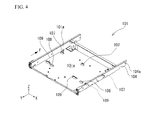
FIG. 4 is a perspective view of a base member; -
FIG. 5 is a perspective view illustrating a front side of a keyboard unit; -
FIG. 6 is a perspective view illustrating a rear side of the keyboard unit; -
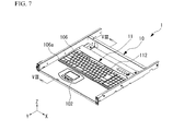
FIG. 7 is a perspective view of the console drawer according to the present embodiment; -
FIG. 8A is a cross sectional view taken along a line VIII-VIII inFIG. 7 ; -
FIG. 8B is a cross sectional view concerning a first engaging unit and a third engaging unit; -
FIG. 9A is a cross sectional view illustrating a state where the keyboard unit is slid, with respect to the cross sectional view ofFIG. 8A ; -
FIG. 9B is a cross sectional view concerning the first engaging unit and the third engaging unit; -
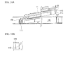
FIG. 10A is a cross sectional view illustrating a state where the keyboard unit is tilted in the cross sectional view ofFIG. 9 ; and -
FIG. 10B is a cross sectional view concerning the first engaging unit and the third engaging unit. -
FIG. 1 is a perspective view illustrating a console drawer stored into a rack. A plurality ofconsole drawers 1 and aserver device 3 are stacked, and stored into a rack 4. Each of theconsole drawers 1 functions as an information input device for operating theserver device 3. - The
console drawer 1 has a shape similar to a portable personal computer, and includes akeyboard unit 1a that inputs information, and adisplay unit 1c that pivotally moves about thekeyboard unit 1a (see code "r"). Theconsole drawer 1 can be drawn from the rack and put in the rack by being slid withguide rail mechanisms 1b provided at both side of theconsole drawer 1. When theconsole drawer 1 is used, theconsole drawer 1 is drawn from the rack 4. When theconsole drawer 1 is not used, theconsole drawer 1 is put in the rack 4. - The
display unit 1c is a thin liquid crystal display, for example. When thedisplay unit 1c is not used, thedisplay unit 1c is closed so as to overlap on a top face of thekeyboard unit 1a. Ahandle 1d is provided on a top end of thedisplay unit 1c. When thedisplay unit 1c is closed, thehandle 1d is located at a front face of theconsole drawer 1. Therefore, a user can easily draw theconsole drawer 1 from the rack 4 and put theconsole drawer 1 in the rack 4 by gripping thehandle 1d. -
FIG. 2 is an exploded perspective view of the console drawer according to a comparative embodiment. Aconsole drawer 9 includes abase member 90 that is a housing, akeyboard unit 91 that is a keyboard device, and acover 92. In the following description, the directions of an X axis, a Y axis and a Z axis inFIG. 2 are expressed as a width direction, a depth direction and a height direction, respectively. Theconsole drawer 9 inFIG. 2 is indicated as a state where thedisplay unit 1c ofFIG. 1 is removed. In the following drawing, the display unit is removed as is the case withFIG. 2 . - The
base member 90 is made of a sheet metal, for example. Thebase member 90 includes a rectangle-like bottom face 900, a pair ofside faces 901 provided at both ends of thebottom face 900 in the width direction, and arear face 913 provided at an end of thebottom face 900 in the depth direction.Guide rails 901a for sliding theconsole drawer 9 when theconsole drawer 9 is attached to the rack 4 are provided on the pair ofside faces 901. - A
pointing device 903, awiring 904 and asubstrate 905 are provided on thebottom face 900. Thepointing device 903 is used for the input of position information or the like, and is electrically connected to thesubstrate 905 via thewiring 904. A LED (Light Emitting Diode) for status indication, a push button switch, an electric circuit and the like are provided on thesubstrate 905. - Three
engaging parts 906 arranged in the width direction andscrew fastening parts 902a and 920b are provided on thebottom face 900. Each of theengaging parts 906 has a gate shape, and the threeengaging parts 906 engage with threeprotrusion parts 912 which are provided at an end in the side of a front face of thekeyboard unit 91. That is, theprotrusion parts 912 are engaged with theengaging parts 906 by being inserted into theengaging parts 906. Theengaging parts 906 are formed by clipping out predetermined parts of thebottom face 900 in a predetermined shape and performing a bending process on the clipped parts. - The
screw fastening parts keyboard unit 91 and thecover 92, respectively. Thekeyboard unit 91 is screwed to twoscrew fastening parts 902a via plate-likefixed parts 910. The fixedparts 910 are provided on both sides of thekeyboard unit 91 so as to extend in the width direction. A hole for inserting ascrew 81 is formed on eachfixed part 910. - In a state where the three
protrusion parts 912 are engaged with the three engagingparts 906 of thebottom face 900, respectively, eachfixed part 910 is screwed to thescrew fastening part 902a of thebottom face 900, so that thekeyboard unit 91 is fixed on thebase member 90. Thekeyboard unit 91 includes anelectric wiring 911 formed with a membrane, for example, and is electrically connected to thesubstrate 905 through theelectric wiring 911. - After the
keyboard unit 91 is fixed on thebase member 90, thecover 92 is attached to thebase member 90 by screwing the twoscrew fastening parts 902b withscrews 80 via screw holes 923. Afirst opening 920 for exposing the top face of thekeyboard unit 91 and a second opening 921 for exposing the top face of thepointing device 903 are formed on thecover 92. Moreover, thecover 92 has a light-penetratingpart 922 for penetrating the light of the LED. - Since the
screw 81 is used for attachment of thekeyboard unit 91, theconsole drawer 9 according to the comparative embodiment requires a tool, such as a driver. When theconsole drawer 9 is assembled, it is necessary to attach thekeyboard unit 91 and thecover 92 to thebase member 90 in order of thekeyboard unit 91 and thecover 92. The console drawer illustrated inFIG. 3 eliminates the necessity of the order of the attachment. -
FIG. 3 is an exploded perspective view of the console drawer according to a present embodiment. Theconsole drawer 1 includes adrawer unit 10 and akeyboard unit 11. Thedrawer unit 10 is formed by attaching acover 100 which is the same as the cover of the comparative embodiment to abase member 101 illustrated inFIG. 4 with ascrew 100a. Also, thekeyboard unit 11 is illustrated inFIGs. 5 and6 .FIG. 5 is a perspective view illustrating a front side of thekeyboard unit 11, andFIG. 6 is a perspective view illustrating a rear side of thekeyboard unit 11. - The
keyboard unit 11 is made, for example, of ABS resin (Acrylonitrile Butadiene Styrene), and, on the whole, has the shape of a rectangle. In thekeyboard unit 11, a plurality of keys are arranged. There is no limitation in the material, the whole shape and the key arrangement of thekeyboard unit 11. - On the contrary, the
drawer unit 10 includes apointing device 102 and a rectangle-like holding part 106 for holding thekeyboard unit 11, and functions as a keyboard holding device. Engaging members that engage with thekeyboard unit 11 are provided in the holdingpart 106, as described later. - The
base member 101 of thedrawer unit 10 is made of a sheet metal as is the case with thebase member 90 of the comparative embodiment described above. Thebase member 101 includes abottom face 101a, a pair of side faces 104 which adjoin thebottom face 101a, and arear face 105.Guide rails 104a for drawing thedrawer unit 10 from the rack 4 and putting thedrawer unit 10 in the rack 4 are provided on the pair of side faces 104, respectively. A through-hole 105a for pulling out an electric wiring to be connected to another device in the rack 4 is provided on therear face 105. - The
keyboard unit 11 includes: twoelastic parts 111 and three first engagingparts 110 that are provided on oneend face 11a in a pair of opposed end faces 11a and 11b; and three second engagingparts 115 that are provided on anotherend face 11b. On the contrary, thedrawer unit 10 includes abuttingparts 108, thirdengaging parts 109 and fourthengaging parts 107 that are provided on thebottom face 101a of thebase member 101. Theelastic parts 111 abut on the abuttingparts 108, and the firstengaging parts 110 and the secondengaging parts 115 engage with the thirdengaging parts 109 and the fourthengaging parts 107, respectively, so that thekeyboard unit 11 is held by the holdingpart 106 of thedrawer unit 10. - Each of the
elastic parts 111 is a plate spring integrally molded with a housing of thekeyboard unit 11, and eachabutting part 108 is a tabular member stood in a direction perpendicular to thebottom face 101a. When thekeyboard unit 11 is held in the holdingpart 106 of thedrawer unit 10, eachelastic part 111 abuts on eachabutting part 108 provided in thedrawer unit 10, and biases thekeyboard unit 11 in a direction toward theend face 11b from theend face 11a (see code "F" ofFIGs. 4 to 6 ). - A pair of
protrusion parts 111a are provided at both sides of eachelastic part 111 so as to interrupt the compression of theelastic parts 111 by abutting on the abutting parts 108 (see an enlarged part P1 ofFIG. 5 ). Therefore, a size in the width direction of eachabutting part 108 is set longer than that of eachelastic part 111. According to the pair ofprotrusion parts 111a, eachelastic part 111 is prevented from being damaged by superfluous compression. Eachelastic part 111 is not limited to plate spring, and may be another elastic member, such as a spring or urethane. Theelastic parts 111 may be formed separately from thekeyboard unit 11. When theelastic parts 111 are integrally molded with thekeyboard unit 11, the manufacture thereof is easy. - Each first
engaging part 110 is a hexagonal tabular member obtained by cutting off corners of both sides of a rectangle (see an enlarged part P2 ofFIG. 5 ), and a taper part is formed at a bottom part of each first engaging part 110 (see a code "110a" ofFIGs. 8B and9B ). Each secondengaging part 115 is a protrusion member extended in the width direction (see an enlarged part P3 ofFIG. 6 ), and taper parts are formed at top and bottom parts of each secondengaging part 115. The firstengaging parts 110 and the secondengaging parts 115 may be integrally molded with thekeyboard unit 11, or may be formed separately from thekeyboard unit 11. When the firstengaging parts 110 and the secondengaging parts 115 are formed separately from thekeyboard unit 11, the manufacture thereof is easy. - On the contrary, the third
engaging parts 109 and the fourthengaging parts 107 are gate-like members. The firstengaging parts 110 and the secondengaging parts 115 are inserted into holes provided on the thirdengaging parts 109 and the fourthengaging parts 107, so that the thirdengaging parts 109 and the fourthengaging parts 107 are engaged with the firstengaging parts 110 and the secondengaging parts 115. The abuttingparts 108, the thirdengaging parts 109 and the fourthengaging parts 107 are formed by clipping out predetermined parts of thebottom face 101a in predetermined shapes and performing a bending process on the clipped parts. - The abutting
parts 108 and the thirdengaging parts 109 are arranged in the width direction, and arranged at different positions from the fourthengaging parts 107 in the depth direction. When theelastic parts 111 abut on the abuttingparts 108, the firstengaging parts 110 are configured to engage with the thirdengaging parts 109 of thedrawer unit 10. On the contrary, the secondengaging parts 115 are configured to engage with the fourthengaging parts 107 of thedrawer unit 10 by the bias of theelastic parts 111. - Therefore, when the
elastic parts 111 are pushed and compressed by the abuttingparts 108, an engaged state of the secondengaging parts 115 and the fourthengaging parts 107 is released. Thereby, thekeyboard unit 11 is pushed into the holdingpart 106 of thedrawer unit 10, or removed from the holdingpart 106. That is, by sliding thekeyboard unit 11 in an opposite direction to the depth direction, thekeyboard unit 11 can be attached or detached to thedrawer unit 10. - In order to detach the
keyboard unit 11 from thedrawer unit 10 easily, a pair ofconcave portions 112 are formed in an end of the top face of thekeyboard unit 11, as illustrated inFIGs. 3 and6 . Each of theconcave portions 112 is a groove-like space in which taper parts are formed on both side faces of theconcave portion 112 in the width direction. The user inserts fingers into the pair ofconcave portions 112, and can move thekeyboard unit 1a so that theelastic parts 111 are compressed. - The
keyboard unit 11 includes anextended part 113 that is extended from an end of the rear face. Anelectric wiring 114 similar to theelectric wiring 911 of thekeyboard unit 91 according to the comparative embodiment is provided on theend face 11b under theextended part 113. Theelectric wiring 114 is connected to a connector 103 (seeFIG. 3 ) provided in the corner of the holdingpart 106 of thedrawer unit 10. The connection to theconnector 103 is performed in advance of the attachment of thekeyboard unit 11 to thedrawer unit 10. -
FIG. 7 is a perspective view illustrating a state where thekeyboard unit 11 is held in the holdingpart 106 of thedrawer unit 10, i.e., a perspective view of the console drawer according to the present embodiment. Thekeyboard unit 11 includes agap 106a provided between an end of thepointing device 102 and thedrawer unit 10. When thekeyboard unit 11 is detached from thedrawer unit 10, thekeyboard unit 11 is slid in a direction reducing thegap 106a so that theelastic parts 111 are compressed. -
FIGs. 8A to 10B are cross sectional views taken along a line VIII-VIII inFIG. 7 , and illustrate a process in which thekeyboard unit 11 is detached from thedrawer unit 10.FIGs. 8A ,9A and10A illustrate the states of the abuttingparts 108, theelastic parts 111, the secondengaging parts 115 and the fourthengaging parts 107. On the contrary,FIGs. 8B ,9B and10B illustrate the states of the firstengaging parts 110 and the thirdengaging parts 109. -
FIG. 8A illustrates a state where thekeyboard unit 11 is held in the holdingpart 106. In this state, theelastic parts 111 abut on the abuttingparts 108 and bias thekeyboard unit 11 in the depth direction. The secondengaging parts 115 are engaged with the fourthengaging parts 107 by the bias of theelastic parts 111. That is, thekeyboard unit 11 is pushed by a bias force of theelastic parts 111, so that the secondengaging parts 115 are engaged with the fourthengaging parts 107. The firstengaging parts 110 are engaged with the thirdengaging parts 109. -
FIG. 9A illustrates a state where thekeyboard unit 11 is slid in the direction of the compression of the elastic parts 111 (see a code "D1" ofFIG. 8A ). In this case, theelastic parts 111 abut on the abuttingparts 108 in a state where theelastic parts 111 are compressed, and the firstengaging parts 110 maintain an engaged state with the thirdengaging parts 109. Since an engaged state of the secondengaging parts 115 and the fourthengaging parts 107 is released by the displacement of thekeyboard unit 11, theend face 11b which is the rear face of thekeyboard unit 11 becomes free. - The
keyboard unit 11 has ataper part 11c that is formed on a bottom face of thekeyboard unit 11, and extends from theend face 11a which is a front side of the keyboard unit 11 (see an enlarged part P4 ofFIG. 9 ). The firstengaging parts 110 also havetaper parts 110a. Therefore, theend face 11b which is a rear side of thekeyboard unit 11 becomes free, so that thekeyboard unit 11 can tilt by an angle θ to thebottom face 101a. Thetaper part 11c is formed such that a distance between thetaper part 11c and thebottom face 101a increases toward theend face 11a. -
FIG. 10A illustrates a state where thekeyboard unit 11 is pivotally moved (see a code "D2" ofFIG .9A ) and is tilted by the angle θ of thetaper part 11c. In this case, theelastic parts 111 abut on the abuttingparts 108 in a restoration state, and the firstengaging parts 110 maintain an engaged state with the thirdengaging parts 109. - Since the
keyboard unit 11 tilts by the angle θ, theend face 11b is located in the outside of the holdingpart 106. Therefore, thekeyboard unit 11 moves in the depth direction (see a code "D3" ofFIG 10A ), so that theelastic parts 111 are away from the abuttingparts 108, and the engaged state of the firstengaging parts 110 and the thirdengaging parts 109 is released. Thereby, thekeyboard unit 11 is detached from thedrawer unit 10. Here, attachment of thekeyboard unit 11 to thedrawer unit 10 is performed by performing a procedure that is reverse to the procedure described until now. - As described above, since the first
engaging parts 110 provided on any one of the pair of opposed end faces 11a and 11b and the secondengaging parts 115 provided on another one of the end faces engage with the thirdengaging parts 109 and the fourthengaging parts 107 that are provided on thedrawer unit 10, respectively, thekeyboard unit 11 is held in thedrawer unit 10. - The
elastic parts 111 abut on the abuttingparts 108 provided on thedrawer unit 10 and bias thekeyboard unit 11 in a direction toward theend face 11b from theend face 11a. The secondengaging parts 115 are engaged with the fourthengaging parts 107 by the bias of theelastic parts 111. Therefore, thekeyboard unit 11 is moved in the direction of the compression of theelastic parts 111, so that the engagement between the secondengaging parts 115 and the fourthengaging parts 107 is released, and theend face 11b becomes free. As a result, thekeyboard unit 11 can be easily detached from thedrawer unit 10. On the contrary, thekeyboard unit 11 can be easily attached to thedrawer unit 10 in the same manner as the detachment. Thus, thekeyboard unit 11 can be attached to or detached from thedrawer unit 10 without using a tool. - In the present embodiment, there is no limitation in the shape of the first
engaging parts 110, the secondengaging parts 115, the thirdengaging parts 109 and the fourthengaging parts 107. For example, each of the firstengaging parts 110 and the secondengaging parts 115 of thekeyboard unit 11 may have a concave shape, and each of the thirdengaging parts 109 and the fourthengaging parts 107 may have a protrusion shape. - Although in the present embodiment, the console drawer is explained as the information input device, the information input device is not limited to this. The present embodiment is also applied to another portable computer device, for example.
- Although the embodiments of the present invention have been described in detail, it should be understood that the various change, substitutions, and alterations could be made hereto without departing from the spirit and scope of the invention.
Claims (7)
- A keyboard device (11) characterized by comprising:an elastic portion (111) that is provided on any one of a pair of opposed end faces (11a, 11b), abuts on an abutting portion (108) provided on a keyboard holding device (10), and biases the keyboard device in a direction toward another end (11b) face from one end face (11a) on which the elastic portion is provided;a first engaging portion (110) that is provided on the one end face, and engages with a third engaging portion (109) provided on the keyboard holding device; anda second engaging portion (115) that is provided on the another end face, and engages with a fourth engaging portion (107) provided on the keyboard holding device by the bias of the elastic portion.
- The keyboard device according to claim 1, further characterized by comprising
a concave portion (112) for attaching and detaching the keyboard device that is formed on a top face of the keyboard device. - The keyboard device according to claim 1 or claim 2, further characterized by comprising
a taper portion (11c) that is formed at a bottom face of the keyboard device, and extends from the one end face. - The keyboard device according to any one of claims 1 to 3, characterized in that
the elastic portion is a plate spring integrally molded with a housing of the keyboard device. - The keyboard device according to and one of claims 1 to 4, further characterized by comprising
a pair of protrusion portions (111a) that are provided at both sides of the elastic portion so as to interrupt compression of the elastic portion by abutting on the abutting portion. - A keyboard holding device (10) characterized by comprising:a holding portion (106) that holds a keyboard device (11);an abutting portion (108) that is provided in the holding portion, and abuts on an elastic portion (111), the elastic portion being provided on any one of a pair of opposed end faces (11a, 11b) included in the keyboard device;a third engaging portion (109) that is provided in the holding portion, and engages with a first engaging portion, the first engaging portion being provided on one end face (11a) of the keyboard device on which the elastic portion is provided; anda fourth engaging portion (107) that is provided in the holding portion, and engages with a second engaging portion, the second engaging portion being provided on another end face (11b) of the keyboard device.
- An information input device characterized by comprising:a keyboard device (11) as claimed in any one of claims 1 to 5; anda keyboard holding device (10) as claimed in claim 6.
Applications Claiming Priority (1)
| Application Number | Priority Date | Filing Date | Title |
|---|---|---|---|
| JP2012038828A JP5918566B2 (en) | 2012-02-24 | 2012-02-24 | Keyboard device, keyboard holding device, and information input device |
Publications (3)
| Publication Number | Publication Date |
|---|---|
| EP2631735A2 true EP2631735A2 (en) | 2013-08-28 |
| EP2631735A3 EP2631735A3 (en) | 2016-04-20 |
| EP2631735B1 EP2631735B1 (en) | 2019-05-08 |
Family
ID=47225973
Family Applications (1)
| Application Number | Title | Priority Date | Filing Date |
|---|---|---|---|
| EP12190880.0A Active EP2631735B1 (en) | 2012-02-24 | 2012-10-31 | Keyboard device, keyboard holding device and information input device |
Country Status (4)
| Country | Link |
|---|---|
| US (1) | US9025323B2 (en) |
| EP (1) | EP2631735B1 (en) |
| JP (1) | JP5918566B2 (en) |
| CN (1) | CN103294209B (en) |
Families Citing this family (53)
| Publication number | Priority date | Publication date | Assignee | Title |
|---|---|---|---|---|
| US10524570B2 (en) * | 2018-04-03 | 2020-01-07 | GM Global Technology Operations LLC | Console drawer assembly with dampening mechanism |
| CN109041464A (en) * | 2018-09-14 | 2018-12-18 | 广东利通科技投资有限公司 | External clamshell operates key board unit |
| CN110220095A (en) * | 2019-04-15 | 2019-09-10 | 厦门翟湾电脑有限公司 | A kind of keyboard fixed frame |
| US12560960B2 (en) | 2021-12-13 | 2026-02-24 | Dell Products L.P. | Modular information handling system and subscription deployment thereof |
| US11907042B2 (en) | 2021-12-13 | 2024-02-20 | Dell Products L.P. | Reduction of high battery voltage by ratios using a main board for power supply of processing unit based on battery voltage changes over time |
| US11829223B2 (en) | 2021-12-13 | 2023-11-28 | Dell Products L.P. | Information handling system battery disposition automated using performance metrics |
| US12282407B2 (en) | 2021-12-13 | 2025-04-22 | Dell Products L.P. | Information handling system hinge disposition automated using performance metrics |
| US12189437B2 (en) | 2021-12-13 | 2025-01-07 | Dell Products L.P. | Modular speakers for portable information handling system audio |
| US11579663B1 (en) * | 2021-12-13 | 2023-02-14 | Dell Products L.P. | Modular information handling system with automated housing cover removal |
| US11915207B2 (en) | 2021-12-13 | 2024-02-27 | Dell Products L.P. | Modular information handling system with automated display removal |
| US12235625B2 (en) | 2021-12-13 | 2025-02-25 | Dell Products L.P. | Information handling system keyboard disposition automated using performance metrics |
| US12223473B2 (en) | 2021-12-13 | 2025-02-11 | Dell Products L.P. | Information handling system main board disposition automated using performance metrics |
| US12189370B2 (en) | 2021-12-13 | 2025-01-07 | Dell Products L.P. | Information handling system display backplane vapor chamber |
| US12354509B2 (en) | 2021-12-13 | 2025-07-08 | Dell Products L.P. | Information handling system display disposition automated using performance metrics |
| US12222769B2 (en) | 2021-12-13 | 2025-02-11 | Dell Products L.P. | Modular information handling system component connections |
| US12306618B2 (en) | 2021-12-13 | 2025-05-20 | Dell Products L.P. | Information handling system disposition automated using system metrics |
| TWM626897U (en) * | 2021-12-16 | 2022-05-11 | 美商海盜船記憶體股份有限公司 | Modular data output device |
| US12416948B2 (en) | 2022-12-14 | 2025-09-16 | Dell Products L.P. | Information handling system keyboard support with rail guide structure assembly to a housing rail |
| US11914428B1 (en) | 2022-12-14 | 2024-02-27 | Dell Products L.P. | Portable information handling system keyboard assembly having separable palm rest |
| US12498772B2 (en) | 2022-12-14 | 2025-12-16 | Dell Products L.P. | Information handling system circuit board retention with bi-stable flexture plate |
| US12223119B2 (en) | 2022-12-14 | 2025-02-11 | Dell Products L.P. | Portable information handling system modular keyboard having removable lattice and keys |
| US12306672B2 (en) | 2022-12-14 | 2025-05-20 | Dell Products L.P. | Portable information handling system keyboard membrane having liquid detection |
| US12443220B2 (en) | 2022-12-14 | 2025-10-14 | Dell Products L.P. | Information handling system keyboard support with internal component assembly features |
| US12468358B2 (en) | 2022-12-14 | 2025-11-11 | Dell Products L.P. | Information handling system motherboard battery cable free connector |
| US12560976B2 (en) | 2022-12-14 | 2026-02-24 | Dell Products L.P. | Information handling system security lock and keystone housing assembly |
| US11832069B1 (en) | 2022-12-14 | 2023-11-28 | Dell Products L.P. | Information handling system speaker with dampened speaker signal interface |
| US12446184B2 (en) | 2022-12-14 | 2025-10-14 | Dell Products L.P. | Information handling system serial thermal solution with motherboard engagement |
| US12585421B2 (en) | 2022-12-14 | 2026-03-24 | Dell Products L.P. | Information handling system keyboard membrane with speaker interface |
| US12225684B2 (en) | 2022-12-14 | 2025-02-11 | Dell Products L.P. | Information handling system keyboard motherboard and thermal solution engagement |
| US11740707B1 (en) | 2022-12-14 | 2023-08-29 | Dell Products L.P. | Portable information handling system keyboard membrane having serial connector hub |
| US12353640B2 (en) | 2022-12-14 | 2025-07-08 | Dell Products L.P. | Information handling system keyboard support with rail guide structure assembly to a housing rail |
| US12216512B2 (en) | 2022-12-14 | 2025-02-04 | Dell Products L.P. | Information handling system retention nut for automated assembly and disassembly |
| JP7303477B1 (en) | 2023-01-19 | 2023-07-05 | 富士通クライアントコンピューティング株式会社 | Electronics |
| US12436899B2 (en) | 2023-01-30 | 2025-10-07 | Dell Products L.P. | Information handling system peripheral device health state tracking for enhanced reuse and recycling |
| US12470080B2 (en) | 2023-01-30 | 2025-11-11 | Dell Products L.P. | Information handling system battery charge arbitration factoring energy consumption and energy source |
| US12602666B2 (en) | 2023-01-30 | 2026-04-14 | Dell Products L.P. | Information handling system micro manufacturing center for reuse and recycling factoring inventory |
| US12499420B2 (en) | 2023-01-30 | 2025-12-16 | Dell Products L.P. | Information handling system peripheral device health state tracking for enhanced reuse and recycling |
| US12523985B2 (en) | 2023-01-30 | 2026-01-13 | Dell Products L.P. | Information handling system micro manufacturing center for reuse and recycling factoring carbon footprint |
| US12602667B2 (en) | 2023-01-30 | 2026-04-14 | Dell Products L.P. | Information handling system secure keyboard health state tracking for enhanced reuse and recycling |
| US12493859B2 (en) | 2023-01-30 | 2025-12-09 | Dell Products L.P. | Information handling system component health state tracking for enhanced reuse and recycling |
| US12554293B2 (en) | 2023-09-08 | 2026-02-17 | Dell Products L.P. | Information handling system display cable to hinge-up camera interface |
| US12386400B2 (en) | 2023-09-08 | 2025-08-12 | Dell Products L.P. | Information handling system cable backplane with snap in cable retention |
| US12499022B2 (en) | 2023-09-08 | 2025-12-16 | Dell Products L.P. | Information handling system display cable link training to monitor for cable failures |
| US12578772B2 (en) | 2023-09-08 | 2026-03-17 | Dell Products L.P. | Information handling system power use telemetry to predict system state of health |
| US12386431B2 (en) | 2023-09-08 | 2025-08-12 | Dell Products L.P. | Information handling system keyboard membrane integrated high speed input/output connection |
| US12524046B2 (en) | 2023-10-04 | 2026-01-13 | Dell Products L.P. | Modular portable information handling system hinge with selectively disengaged rotation stop |
| US12360611B2 (en) | 2023-10-17 | 2025-07-15 | Dell Products L.P. | Information handling system keyboard lighting and language by key lattice coupling |
| US12602770B2 (en) | 2023-10-17 | 2026-04-14 | Dell Products L.P. | Information handling system visual image inspection to support hinge reuse and recycling |
| US12468354B2 (en) | 2023-10-27 | 2025-11-11 | Dell Products L.P. | Information handling system speaker magnet to hold housing portions in a closed position |
| US12436578B2 (en) | 2023-10-27 | 2025-10-07 | Dell Products L.P. | Information handling system speaker magnet to hold housing portions in a closed position |
| US12468353B2 (en) | 2023-10-27 | 2025-11-11 | Dell Products L.P. | Information handling system speaker identification to set audio drive settings |
| US20260010205A1 (en) * | 2024-07-03 | 2026-01-08 | Lenovo (Singapore) Pte. Ltd. | Electronic apparatus and manufacturing method thereof |
| US20260079541A1 (en) * | 2024-09-18 | 2026-03-19 | Dell Products L.P. | Rapid assembly keyboard |
Citations (3)
| Publication number | Priority date | Publication date | Assignee | Title |
|---|---|---|---|---|
| JPH0876881A (en) | 1994-09-06 | 1996-03-22 | Citizen Watch Co Ltd | Attaching/detaching mechanism of keyboard module in information equipment |
| JP2002236523A (en) | 2001-09-10 | 2002-08-23 | Toshiba Corp | Information processing device |
| JP2009104398A (en) | 2007-10-23 | 2009-05-14 | Fujitsu Component Ltd | Console drawer |
Family Cites Families (11)
| Publication number | Priority date | Publication date | Assignee | Title |
|---|---|---|---|---|
| JPS57181078U (en) * | 1981-05-12 | 1982-11-17 | ||
| US7780962B2 (en) * | 1997-10-09 | 2010-08-24 | Wellstat Biologics Corporation | Treatment of neoplasms with RNA viruses |
| US6212066B1 (en) * | 1999-09-24 | 2001-04-03 | Apple Computer, Inc. | Portable computer with removable keyboard |
| TWI254197B (en) * | 1999-11-11 | 2006-05-01 | Darfon Electronics Corp | Keyboard device capable of being fixed on a portable computer |
| TW530253B (en) * | 2000-10-13 | 2003-05-01 | Wistron Corp | Human engineering keyboard |
| TW492557U (en) * | 2000-10-23 | 2002-06-21 | Darfon Electronics Corp | Engaging mechanism for removable keyboard module |
| JP3672249B2 (en) * | 2001-09-25 | 2005-07-20 | インターナショナル・ビジネス・マシーンズ・コーポレーション | Computer device, keyboard, keyboard unit, bezel |
| TW577571U (en) * | 2003-03-25 | 2004-02-21 | Hon Hai Prec Ind Co Ltd | Keyboard assembly |
| US7510342B2 (en) * | 2006-06-15 | 2009-03-31 | Microsoft Corporation | Washable keyboard |
| DE102009013077A1 (en) * | 2009-03-13 | 2010-09-16 | Siemens Aktiengesellschaft | Operating device for operating a machine from automation technology |
| TWI408530B (en) * | 2010-03-26 | 2013-09-11 | Wistron Corp | Portable electronic device having a pop-up keyboard |
-
2012
- 2012-02-24 JP JP2012038828A patent/JP5918566B2/en active Active
- 2012-10-31 EP EP12190880.0A patent/EP2631735B1/en active Active
- 2012-12-05 CN CN201210517365.2A patent/CN103294209B/en active Active
-
2013
- 2013-01-25 US US13/750,010 patent/US9025323B2/en active Active
Patent Citations (3)
| Publication number | Priority date | Publication date | Assignee | Title |
|---|---|---|---|---|
| JPH0876881A (en) | 1994-09-06 | 1996-03-22 | Citizen Watch Co Ltd | Attaching/detaching mechanism of keyboard module in information equipment |
| JP2002236523A (en) | 2001-09-10 | 2002-08-23 | Toshiba Corp | Information processing device |
| JP2009104398A (en) | 2007-10-23 | 2009-05-14 | Fujitsu Component Ltd | Console drawer |
Also Published As
| Publication number | Publication date |
|---|---|
| EP2631735B1 (en) | 2019-05-08 |
| US20130222993A1 (en) | 2013-08-29 |
| JP2013175030A (en) | 2013-09-05 |
| CN103294209B (en) | 2016-06-15 |
| JP5918566B2 (en) | 2016-05-18 |
| EP2631735A3 (en) | 2016-04-20 |
| CN103294209A (en) | 2013-09-11 |
| US9025323B2 (en) | 2015-05-05 |
Similar Documents
| Publication | Publication Date | Title |
|---|---|---|
| EP2631735B1 (en) | Keyboard device, keyboard holding device and information input device | |
| US11474566B2 (en) | Electronic device | |
| US9141146B2 (en) | Latch device and computer system using the same | |
| US20050041378A1 (en) | Electronic apparatus having a housing | |
| CN101098595B (en) | Electronic devices with battery covers | |
| US9740243B2 (en) | Housing of electronic device and electronic device | |
| US9990007B2 (en) | Stand device and stand-equipped portable information device | |
| JP5181844B2 (en) | Keyboard, electronic device, method for manufacturing keyboard, method for manufacturing electronic device, and keyboard component | |
| US20170255237A1 (en) | Housing used in monitor of industrial computer, monitor used in industrial computer, and industrial computer | |
| CN110047681A (en) | Key | |
| US20120152717A1 (en) | Keyboard and electronic apparatus | |
| US8537530B2 (en) | Electronic device | |
| US7751197B2 (en) | Fastening device, module mounting mechanism and information processing apparatus | |
| US20070002025A1 (en) | Keyboard attachment assembly for a computer device | |
| CN2842526Y (en) | Electronic apparatus | |
| EP2273581B1 (en) | Locking mechanism for a cover for a housing of an electronic device | |
| CN103163965B (en) | The installation constitution of keyboard and electronic equipment | |
| TWI727309B (en) | Sinkable keyboard device | |
| US8132975B2 (en) | Keyboard stiffening system | |
| JP2005100173A (en) | Information equipment | |
| EP4142268B1 (en) | Electronic device | |
| JP2011197907A (en) | Input pen holding device and electronic equipment including the same | |
| US20130284573A1 (en) | Keyboard device | |
| US20120154998A1 (en) | Electronic apparatus | |
| CN222826267U (en) | Keyboards and electronic devices |
Legal Events
| Date | Code | Title | Description |
|---|---|---|---|
| PUAI | Public reference made under article 153(3) epc to a published international application that has entered the european phase |
Free format text: ORIGINAL CODE: 0009012 |
|
| AK | Designated contracting states |
Kind code of ref document: A2 Designated state(s): AL AT BE BG CH CY CZ DE DK EE ES FI FR GB GR HR HU IE IS IT LI LT LU LV MC MK MT NL NO PL PT RO RS SE SI SK SM TR |
|
| AX | Request for extension of the european patent |
Extension state: BA ME |
|
| PUAL | Search report despatched |
Free format text: ORIGINAL CODE: 0009013 |
|
| AK | Designated contracting states |
Kind code of ref document: A3 Designated state(s): AL AT BE BG CH CY CZ DE DK EE ES FI FR GB GR HR HU IE IS IT LI LT LU LV MC MK MT NL NO PL PT RO RS SE SI SK SM TR |
|
| AX | Request for extension of the european patent |
Extension state: BA ME |
|
| RIC1 | Information provided on ipc code assigned before grant |
Ipc: H05K 7/14 20060101ALI20160315BHEP Ipc: G06F 1/16 20060101AFI20160315BHEP Ipc: G06F 3/02 20060101ALI20160315BHEP |
|
| 17P | Request for examination filed |
Effective date: 20161018 |
|
| RBV | Designated contracting states (corrected) |
Designated state(s): AL AT BE BG CH CY CZ DE DK EE ES FI FR GB GR HR HU IE IS IT LI LT LU LV MC MK MT NL NO PL PT RO RS SE SI SK SM TR |
|
| STAA | Information on the status of an ep patent application or granted ep patent |
Free format text: STATUS: REQUEST FOR EXAMINATION WAS MADE |
|
| R17P | Request for examination filed (corrected) |
Effective date: 20161018 |
|
| GRAP | Despatch of communication of intention to grant a patent |
Free format text: ORIGINAL CODE: EPIDOSNIGR1 |
|
| STAA | Information on the status of an ep patent application or granted ep patent |
Free format text: STATUS: GRANT OF PATENT IS INTENDED |
|
| RIC1 | Information provided on ipc code assigned before grant |
Ipc: G06F 1/16 20060101AFI20180926BHEP Ipc: H05K 7/14 20060101ALI20180926BHEP Ipc: G06F 3/02 20060101ALI20180926BHEP Ipc: G06F 3/023 20060101ALI20180926BHEP |
|
| INTG | Intention to grant announced |
Effective date: 20181024 |
|
| GRAJ | Information related to disapproval of communication of intention to grant by the applicant or resumption of examination proceedings by the epo deleted |
Free format text: ORIGINAL CODE: EPIDOSDIGR1 |
|
| STAA | Information on the status of an ep patent application or granted ep patent |
Free format text: STATUS: REQUEST FOR EXAMINATION WAS MADE |
|
| RIN1 | Information on inventor provided before grant (corrected) |
Inventor name: IIZUKA, KOJI |
|
| RAP1 | Party data changed (applicant data changed or rights of an application transferred) |
Owner name: FUJITSU COMPONENT LIMITED |
|
| GRAR | Information related to intention to grant a patent recorded |
Free format text: ORIGINAL CODE: EPIDOSNIGR71 |
|
| GRAS | Grant fee paid |
Free format text: ORIGINAL CODE: EPIDOSNIGR3 |
|
| STAA | Information on the status of an ep patent application or granted ep patent |
Free format text: STATUS: GRANT OF PATENT IS INTENDED |
|
| INTC | Intention to grant announced (deleted) | ||
| GRAA | (expected) grant |
Free format text: ORIGINAL CODE: 0009210 |
|
| STAA | Information on the status of an ep patent application or granted ep patent |
Free format text: STATUS: THE PATENT HAS BEEN GRANTED |
|
| INTG | Intention to grant announced |
Effective date: 20190328 |
|
| AK | Designated contracting states |
Kind code of ref document: B1 Designated state(s): AL AT BE BG CH CY CZ DE DK EE ES FI FR GB GR HR HU IE IS IT LI LT LU LV MC MK MT NL NO PL PT RO RS SE SI SK SM TR |
|
| REG | Reference to a national code |
Ref country code: GB Ref legal event code: FG4D |
|
| REG | Reference to a national code |
Ref country code: CH Ref legal event code: EP Ref country code: AT Ref legal event code: REF Ref document number: 1131194 Country of ref document: AT Kind code of ref document: T Effective date: 20190515 |
|
| REG | Reference to a national code |
Ref country code: IE Ref legal event code: FG4D |
|
| REG | Reference to a national code |
Ref country code: DE Ref legal event code: R096 Ref document number: 602012059805 Country of ref document: DE |
|
| REG | Reference to a national code |
Ref country code: NL Ref legal event code: MP Effective date: 20190508 |
|
| REG | Reference to a national code |
Ref country code: LT Ref legal event code: MG4D |
|
| PG25 | Lapsed in a contracting state [announced via postgrant information from national office to epo] |
Ref country code: PT Free format text: LAPSE BECAUSE OF FAILURE TO SUBMIT A TRANSLATION OF THE DESCRIPTION OR TO PAY THE FEE WITHIN THE PRESCRIBED TIME-LIMIT Effective date: 20190908 Ref country code: ES Free format text: LAPSE BECAUSE OF FAILURE TO SUBMIT A TRANSLATION OF THE DESCRIPTION OR TO PAY THE FEE WITHIN THE PRESCRIBED TIME-LIMIT Effective date: 20190508 Ref country code: SE Free format text: LAPSE BECAUSE OF FAILURE TO SUBMIT A TRANSLATION OF THE DESCRIPTION OR TO PAY THE FEE WITHIN THE PRESCRIBED TIME-LIMIT Effective date: 20190508 Ref country code: NL Free format text: LAPSE BECAUSE OF FAILURE TO SUBMIT A TRANSLATION OF THE DESCRIPTION OR TO PAY THE FEE WITHIN THE PRESCRIBED TIME-LIMIT Effective date: 20190508 Ref country code: AL Free format text: LAPSE BECAUSE OF FAILURE TO SUBMIT A TRANSLATION OF THE DESCRIPTION OR TO PAY THE FEE WITHIN THE PRESCRIBED TIME-LIMIT Effective date: 20190508 Ref country code: HR Free format text: LAPSE BECAUSE OF FAILURE TO SUBMIT A TRANSLATION OF THE DESCRIPTION OR TO PAY THE FEE WITHIN THE PRESCRIBED TIME-LIMIT Effective date: 20190508 Ref country code: LT Free format text: LAPSE BECAUSE OF FAILURE TO SUBMIT A TRANSLATION OF THE DESCRIPTION OR TO PAY THE FEE WITHIN THE PRESCRIBED TIME-LIMIT Effective date: 20190508 Ref country code: FI Free format text: LAPSE BECAUSE OF FAILURE TO SUBMIT A TRANSLATION OF THE DESCRIPTION OR TO PAY THE FEE WITHIN THE PRESCRIBED TIME-LIMIT Effective date: 20190508 Ref country code: NO Free format text: LAPSE BECAUSE OF FAILURE TO SUBMIT A TRANSLATION OF THE DESCRIPTION OR TO PAY THE FEE WITHIN THE PRESCRIBED TIME-LIMIT Effective date: 20190808 |
|
| PG25 | Lapsed in a contracting state [announced via postgrant information from national office to epo] |
Ref country code: RS Free format text: LAPSE BECAUSE OF FAILURE TO SUBMIT A TRANSLATION OF THE DESCRIPTION OR TO PAY THE FEE WITHIN THE PRESCRIBED TIME-LIMIT Effective date: 20190508 Ref country code: GR Free format text: LAPSE BECAUSE OF FAILURE TO SUBMIT A TRANSLATION OF THE DESCRIPTION OR TO PAY THE FEE WITHIN THE PRESCRIBED TIME-LIMIT Effective date: 20190809 Ref country code: LV Free format text: LAPSE BECAUSE OF FAILURE TO SUBMIT A TRANSLATION OF THE DESCRIPTION OR TO PAY THE FEE WITHIN THE PRESCRIBED TIME-LIMIT Effective date: 20190508 Ref country code: BG Free format text: LAPSE BECAUSE OF FAILURE TO SUBMIT A TRANSLATION OF THE DESCRIPTION OR TO PAY THE FEE WITHIN THE PRESCRIBED TIME-LIMIT Effective date: 20190808 |
|
| REG | Reference to a national code |
Ref country code: AT Ref legal event code: MK05 Ref document number: 1131194 Country of ref document: AT Kind code of ref document: T Effective date: 20190508 |
|
| PG25 | Lapsed in a contracting state [announced via postgrant information from national office to epo] |
Ref country code: AT Free format text: LAPSE BECAUSE OF FAILURE TO SUBMIT A TRANSLATION OF THE DESCRIPTION OR TO PAY THE FEE WITHIN THE PRESCRIBED TIME-LIMIT Effective date: 20190508 Ref country code: DK Free format text: LAPSE BECAUSE OF FAILURE TO SUBMIT A TRANSLATION OF THE DESCRIPTION OR TO PAY THE FEE WITHIN THE PRESCRIBED TIME-LIMIT Effective date: 20190508 Ref country code: SK Free format text: LAPSE BECAUSE OF FAILURE TO SUBMIT A TRANSLATION OF THE DESCRIPTION OR TO PAY THE FEE WITHIN THE PRESCRIBED TIME-LIMIT Effective date: 20190508 Ref country code: RO Free format text: LAPSE BECAUSE OF FAILURE TO SUBMIT A TRANSLATION OF THE DESCRIPTION OR TO PAY THE FEE WITHIN THE PRESCRIBED TIME-LIMIT Effective date: 20190508 Ref country code: EE Free format text: LAPSE BECAUSE OF FAILURE TO SUBMIT A TRANSLATION OF THE DESCRIPTION OR TO PAY THE FEE WITHIN THE PRESCRIBED TIME-LIMIT Effective date: 20190508 Ref country code: CZ Free format text: LAPSE BECAUSE OF FAILURE TO SUBMIT A TRANSLATION OF THE DESCRIPTION OR TO PAY THE FEE WITHIN THE PRESCRIBED TIME-LIMIT Effective date: 20190508 |
|
| REG | Reference to a national code |
Ref country code: DE Ref legal event code: R097 Ref document number: 602012059805 Country of ref document: DE |
|
| PG25 | Lapsed in a contracting state [announced via postgrant information from national office to epo] |
Ref country code: SM Free format text: LAPSE BECAUSE OF FAILURE TO SUBMIT A TRANSLATION OF THE DESCRIPTION OR TO PAY THE FEE WITHIN THE PRESCRIBED TIME-LIMIT Effective date: 20190508 Ref country code: IT Free format text: LAPSE BECAUSE OF FAILURE TO SUBMIT A TRANSLATION OF THE DESCRIPTION OR TO PAY THE FEE WITHIN THE PRESCRIBED TIME-LIMIT Effective date: 20190508 |
|
| PLBE | No opposition filed within time limit |
Free format text: ORIGINAL CODE: 0009261 |
|
| STAA | Information on the status of an ep patent application or granted ep patent |
Free format text: STATUS: NO OPPOSITION FILED WITHIN TIME LIMIT |
|
| PG25 | Lapsed in a contracting state [announced via postgrant information from national office to epo] |
Ref country code: TR Free format text: LAPSE BECAUSE OF FAILURE TO SUBMIT A TRANSLATION OF THE DESCRIPTION OR TO PAY THE FEE WITHIN THE PRESCRIBED TIME-LIMIT Effective date: 20190508 |
|
| 26N | No opposition filed |
Effective date: 20200211 |
|
| PG25 | Lapsed in a contracting state [announced via postgrant information from national office to epo] |
Ref country code: PL Free format text: LAPSE BECAUSE OF FAILURE TO SUBMIT A TRANSLATION OF THE DESCRIPTION OR TO PAY THE FEE WITHIN THE PRESCRIBED TIME-LIMIT Effective date: 20190508 |
|
| PG25 | Lapsed in a contracting state [announced via postgrant information from national office to epo] |
Ref country code: MC Free format text: LAPSE BECAUSE OF FAILURE TO SUBMIT A TRANSLATION OF THE DESCRIPTION OR TO PAY THE FEE WITHIN THE PRESCRIBED TIME-LIMIT Effective date: 20190508 Ref country code: SI Free format text: LAPSE BECAUSE OF FAILURE TO SUBMIT A TRANSLATION OF THE DESCRIPTION OR TO PAY THE FEE WITHIN THE PRESCRIBED TIME-LIMIT Effective date: 20190508 |
|
| REG | Reference to a national code |
Ref country code: CH Ref legal event code: PL |
|
| PG25 | Lapsed in a contracting state [announced via postgrant information from national office to epo] |
Ref country code: LU Free format text: LAPSE BECAUSE OF NON-PAYMENT OF DUE FEES Effective date: 20191031 Ref country code: CH Free format text: LAPSE BECAUSE OF NON-PAYMENT OF DUE FEES Effective date: 20191031 Ref country code: LI Free format text: LAPSE BECAUSE OF NON-PAYMENT OF DUE FEES Effective date: 20191031 |
|
| REG | Reference to a national code |
Ref country code: BE Ref legal event code: MM Effective date: 20191031 |
|
| PG25 | Lapsed in a contracting state [announced via postgrant information from national office to epo] |
Ref country code: BE Free format text: LAPSE BECAUSE OF NON-PAYMENT OF DUE FEES Effective date: 20191031 |
|
| PG25 | Lapsed in a contracting state [announced via postgrant information from national office to epo] |
Ref country code: IE Free format text: LAPSE BECAUSE OF NON-PAYMENT OF DUE FEES Effective date: 20191031 |
|
| REG | Reference to a national code |
Ref country code: DE Ref legal event code: R082 Ref document number: 602012059805 Country of ref document: DE Representative=s name: HL KEMPNER PATENTANWAELTE, SOLICITORS (ENGLAND, DE Ref country code: DE Ref legal event code: R082 Ref document number: 602012059805 Country of ref document: DE Representative=s name: HL KEMPNER PATENTANWALT, RECHTSANWALT, SOLICIT, DE Ref country code: DE Ref legal event code: R082 Ref document number: 602012059805 Country of ref document: DE Representative=s name: HL KEMPNER PARTG MBB, DE |
|
| PG25 | Lapsed in a contracting state [announced via postgrant information from national office to epo] |
Ref country code: CY Free format text: LAPSE BECAUSE OF FAILURE TO SUBMIT A TRANSLATION OF THE DESCRIPTION OR TO PAY THE FEE WITHIN THE PRESCRIBED TIME-LIMIT Effective date: 20190508 |
|
| PG25 | Lapsed in a contracting state [announced via postgrant information from national office to epo] |
Ref country code: IS Free format text: LAPSE BECAUSE OF FAILURE TO SUBMIT A TRANSLATION OF THE DESCRIPTION OR TO PAY THE FEE WITHIN THE PRESCRIBED TIME-LIMIT Effective date: 20190908 |
|
| PG25 | Lapsed in a contracting state [announced via postgrant information from national office to epo] |
Ref country code: HU Free format text: LAPSE BECAUSE OF FAILURE TO SUBMIT A TRANSLATION OF THE DESCRIPTION OR TO PAY THE FEE WITHIN THE PRESCRIBED TIME-LIMIT; INVALID AB INITIO Effective date: 20121031 Ref country code: MT Free format text: LAPSE BECAUSE OF FAILURE TO SUBMIT A TRANSLATION OF THE DESCRIPTION OR TO PAY THE FEE WITHIN THE PRESCRIBED TIME-LIMIT Effective date: 20190508 |
|
| PG25 | Lapsed in a contracting state [announced via postgrant information from national office to epo] |
Ref country code: MK Free format text: LAPSE BECAUSE OF FAILURE TO SUBMIT A TRANSLATION OF THE DESCRIPTION OR TO PAY THE FEE WITHIN THE PRESCRIBED TIME-LIMIT Effective date: 20190508 |
|
| PGFP | Annual fee paid to national office [announced via postgrant information from national office to epo] |
Ref country code: GB Payment date: 20250911 Year of fee payment: 14 |
|
| PGFP | Annual fee paid to national office [announced via postgrant information from national office to epo] |
Ref country code: FR Payment date: 20250908 Year of fee payment: 14 |
|
| PGFP | Annual fee paid to national office [announced via postgrant information from national office to epo] |
Ref country code: DE Payment date: 20250902 Year of fee payment: 14 |