EP2631729A1 - Apparatus and method for drive path search - Google Patents
Apparatus and method for drive path search Download PDFInfo
- Publication number
- EP2631729A1 EP2631729A1 EP12157083.2A EP12157083A EP2631729A1 EP 2631729 A1 EP2631729 A1 EP 2631729A1 EP 12157083 A EP12157083 A EP 12157083A EP 2631729 A1 EP2631729 A1 EP 2631729A1
- Authority
- EP
- European Patent Office
- Prior art keywords
- point
- drive path
- mining vehicle
- drive
- data
- Prior art date
- Legal status (The legal status is an assumption and is not a legal conclusion. Google has not performed a legal analysis and makes no representation as to the accuracy of the status listed.)
- Granted
Links
- 238000000034 method Methods 0.000 title claims abstract description 47
- 238000005065 mining Methods 0.000 claims abstract description 151
- 230000008569 process Effects 0.000 claims abstract description 25
- 238000012545 processing Methods 0.000 claims abstract description 7
- 238000003066 decision tree Methods 0.000 claims description 14
- 239000011435 rock Substances 0.000 claims description 14
- 230000015654 memory Effects 0.000 claims description 8
- 238000004590 computer program Methods 0.000 claims description 6
- 238000002474 experimental method Methods 0.000 claims description 5
- 239000000463 material Substances 0.000 claims description 5
- 230000006870 function Effects 0.000 claims description 4
- 238000012360 testing method Methods 0.000 claims description 3
- 230000001052 transient effect Effects 0.000 claims description 3
- 238000010845 search algorithm Methods 0.000 description 19
- 238000012546 transfer Methods 0.000 description 7
- 230000008901 benefit Effects 0.000 description 4
- 238000004422 calculation algorithm Methods 0.000 description 4
- 238000005259 measurement Methods 0.000 description 4
- 238000004088 simulation Methods 0.000 description 4
- 238000003860 storage Methods 0.000 description 3
- 230000005540 biological transmission Effects 0.000 description 2
- 238000004891 communication Methods 0.000 description 2
- 238000005553 drilling Methods 0.000 description 2
- 230000007613 environmental effect Effects 0.000 description 2
- 238000004519 manufacturing process Methods 0.000 description 2
- 230000000007 visual effect Effects 0.000 description 2
- 238000004458 analytical method Methods 0.000 description 1
- 238000004364 calculation method Methods 0.000 description 1
- 235000019994 cava Nutrition 0.000 description 1
- 238000011217 control strategy Methods 0.000 description 1
- 238000001514 detection method Methods 0.000 description 1
- 238000010586 diagram Methods 0.000 description 1
- 239000000428 dust Substances 0.000 description 1
- 230000000694 effects Effects 0.000 description 1
- 230000007257 malfunction Effects 0.000 description 1
- 230000007246 mechanism Effects 0.000 description 1
- 238000012544 monitoring process Methods 0.000 description 1
- 230000003287 optical effect Effects 0.000 description 1
- 230000006403 short-term memory Effects 0.000 description 1
- 230000007480 spreading Effects 0.000 description 1
- 238000003892 spreading Methods 0.000 description 1
- 238000002604 ultrasonography Methods 0.000 description 1
Images


Classifications
-
- G—PHYSICS
- G05—CONTROLLING; REGULATING
- G05D—SYSTEMS FOR CONTROLLING OR REGULATING NON-ELECTRIC VARIABLES
- G05D1/00—Control of position, course or altitude of land, water, air, or space vehicles, e.g. automatic pilot
- G05D1/02—Control of position or course in two dimensions
- G05D1/021—Control of position or course in two dimensions specially adapted to land vehicles
- G05D1/0268—Control of position or course in two dimensions specially adapted to land vehicles using internal positioning means
- G05D1/0274—Control of position or course in two dimensions specially adapted to land vehicles using internal positioning means using mapping information stored in a memory device
-
- G—PHYSICS
- G05—CONTROLLING; REGULATING
- G05D—SYSTEMS FOR CONTROLLING OR REGULATING NON-ELECTRIC VARIABLES
- G05D1/00—Control of position, course or altitude of land, water, air, or space vehicles, e.g. automatic pilot
- G05D1/02—Control of position or course in two dimensions
- G05D1/021—Control of position or course in two dimensions specially adapted to land vehicles
- G05D1/0231—Control of position or course in two dimensions specially adapted to land vehicles using optical position detecting means
- G05D1/0246—Control of position or course in two dimensions specially adapted to land vehicles using optical position detecting means using a video camera in combination with image processing means
- G05D1/0248—Control of position or course in two dimensions specially adapted to land vehicles using optical position detecting means using a video camera in combination with image processing means in combination with a laser
Definitions
- the invention relates to an automatic drive of a mining vehicle in a mine, and particularly to searching for in a data processing device a drive path for the automatic drive of a mining vehicle from a start point to a goal point in a mine.
- the invention further relates to a method for finding a drive path for a mining vehicle in a mine.
- mining vehicles In mines, various mining vehicles, i.e. mobile mining machines, are used. Typical mining vehicles are rock drilling rigs, bolting vehicles, charging devices, loading vehicles, transport vehicles and measuring vehicles. In an automated mine, these vehicles can be unmanned and they can be driven automatically along a predetermined route in a mine. The mining vehicle is provided with means to determine the current location. When the automated mining vehicle is driven off the route, it may be difficult to return the vehicle back to the route.
- An object of the invention is to provide a novel and improved apparatus and method for finding a drive path for an automatic drive of a mining vehicle in a mine.
- the mining vehicle according to the invention is characterized in that the apparatus is configured to: receive data on actual initial position and orientation of the mining vehicle in the mine and input this data as the start point of the drive path; experiment on several different steering movements of the mining vehicle relative to the driving movements to find at least one steering sequence satisfying a collision-free drive path from the start point to the goal point; and select one created steering sequence for executing the found drive path completely.
- the method according to the invention is characterized by receiving actual initial position and orientation data of the mining vehicle in the mine and feeding this data as the start point for the drive path; experimenting on several different steering movements of the mining vehicle relative to the driving movements to find at least one steering sequence satisfying a collision-free drive path from the start point to the goal point; and selecting one created steering sequence for executing the found drive path completely.
- a start point for the drive path to be formed is defined by determining an actual initial position and orientation of the mine vehicle in the mine.
- As a goal or target point for the drive path one predetermined point in the mine is determined.
- the goal point includes at least position data.
- the drive path is generated in a path generator including at least one processor wherein a path search process, or algorithm, is implemented.
- the path search process employs a kinematic model of the mining vehicle and an environment model of the mine and searches for feasible collision-free drive paths between the starting point and the goal point.
- the drive path search process In the drive path search process, several different steering movements relative to driving movements are experimented on in order to find one or more drive path steering sequences allowing a collision-free drive to the chosen goal point in the mine. A collision avoidance examination is applied. As a result of the path search, at least one complete steering sequence is formed in advance for the drive. The created steering sequence defines steering movements as a function of the driving distance. When executing the steering sequence, the distance driven is determined by measuring means of the mining vehicle.
- An advantage of the disclosed solution is that a drive path is generated for each specific situation, which means that the drive path is of a single-use type. This way, the drive path is always generated by taking into account the accurate initial position and orientation of the mining vehicle.
- the generated and accepted drive path is reliable, because the drive path is completely formed before the mining vehicle executes the drive. Thus, any difficulties are taken into account already before the start of the drive and no interruptions occur during the drive.
- One more benefit is that the steering sequence of the drive path determines the steering movements as a function of distance, whereby the driving speed does not affect the control of the drive. This simplifies the control procedure.
- the drive path can be defined without creating any route points provided with position data, such as coordinates.
- a steering sequence is generated for driving a mining vehicle in a mine automatically from a first mine work point to a second mine work point.
- the mining vehicle In the first mine work point, the mining vehicle is operated under manual control and when the operator has completed the manual operations, the path search algorithm is started.
- the mining vehicle may have a random initial position and orientation after the manual operations.
- the mining vehicle can be transfer driven from the first mine work point to the second work point by executing the created steering sequence in a control unit of the mining vehicle.
- the mining vehicle may be a loading vehicle, which is arranged to drive in the mine between a loading point and an unloading point. Loading a bucket of the loading vehicle is a demanding task and difficult to automate.
- the bucket may be filled by driving the vehicle towards a rock pile manually and simultaneously controlling the movements of the bucket manually.
- the manual operation can be stopped and the path search algorithm can be started.
- the path search process determines the initial position and orientation of the mining vehicle at the loading point, whereby a start point is defined.
- a goal point for the search pre-determined position data of the unloading point is used.
- the path search algorithm creates a single-use steering sequence before starting the transfer drive.
- the loading vehicle can be driven under automatic control from the rock pile or loading chute to the unloading chute or conveying system without needing a pre-determined route.
- the mining vehicle is arranged to drive in the mine automatically along a pre-determined main route including a plurality of route points.
- the mine vehicle moves away from the main route and is then returned back to the main route in order to continue the automatic main drive.
- a single-use return path is generated and selected before the return drive is started.
- one route point of the main route is selected as a goal point for the return path.
- the selected route point includes position data.
- the mining vehicle is driven intentionally away from the main route in order to perform mining work in a mining work area located outside the main route.
- the mining vehicle can be driven to the mining work area under the control of an operator.
- the operator may drive the mining vehicle under remote control from a control room located outside the mine, whereby the control commands are transmitted to the control unit of the mine vehicle via data communication means and the operator is provided with visual data of the mining work area.
- the mining vehicle may also include sensors and measuring devices for producing further information for the manual drive.
- the mining vehicle is provided with a teleoperation mode for the manual drive.
- the automatic return drive releases the operator for other tasks.
- the control system is arranged to return the mining vehicle back to the pre-determined main route when the mining vehicle has unexpectedly diverged from the route.
- a situation may occur as a result of malfunction in the navigation system or automatic drive controlling system of the mining vehicle, or possibly also when executing sudden steering movements in order to avoid collision with other mining vehicles or collapsed or dropped rock blocks. Thanks to this embodiment the mining vehicle can be restored to the main route for continuing the automatic production drive after an unexpected incident. This improves the operational reliability of the automatic mining system.
- the disclosed system is intended for underground mines having tunnels and other rock caverns where the mine vehicles can be driven for executing pre-determined mine work in mine working areas.
- the mine vehicles can be driven along the main route for transport or production drive.
- the disclosed system is used in block caving where ore body is undercut and the ore caves naturally downwards a vertical rise.
- gravitational flow of ore is utilized.
- the mine vehicle is a loading vehicle which is driven under manual control from the main route to a branching loading tunnel for loading a bucket and is thereafter reverse driven automatically according to the generated steering sequence back to the main route.
- the path generation algorithm is intended for a short driving distance.
- the length of the drive path is typically less than 100 meters.
- the return route may be only 10 to 40 meters.
- rock surfaces around the mining vehicle are scanned and the scanning data is compared with an environment model of the mine when determining the distance driven during the return drive.
- a benefit of this type of distance measurement is that a possible slippage of the wheels and an uneven driving surface have no influence on the measurement accuracy. This allows exact steering movements during the drive along the generated path.
- a route is generated on the basis of the generated drive path steering sequence.
- the route includes several route points at an interval from each other.
- Each route point includes position data, such as coordinates in a coordinate system.
- the driving sequence does not define any route points provided with coordinate data.
- the drive path steering sequence is stored only into a short-term memory since the sequence is for single-use purpose only.
- the steering sequence may be deleted from the memory after being executed by the control unit of the mining vehicle.
- the steering sequence may be stored temporarily in a transient computer-readable memory.
- the goal point is determined by the operator and is then input into the drive path searching process.
- the data relating to the goal point includes data on the final orientation of the mining vehicle. This way, it is possible to drive the mining vehicle so that the succeeding automatic driving can be started smoothly.
- the goal point is determined by the drive path search algorithm, which may include a control strategy or rules to select the goal point among pre-determined points.
- the search algorithm may update the selection of the goal point during the search process. This way, the search process may be started with a first goal point or target group of goal points, but can be changed to a second goal point when the algorithm determines during the path generation process, that by selecting the second goal point a better end result can be achieved.
- the update of the goal point may allow a better final orientation of the mining vehicle to be achieved, for example.
- an initial position and orientation of the mining vehicle are determined by one or more measuring devices arranged in the mining vehicle.
- At least an initial position, and possibly also the orientation, of the mining vehicle is determined by scanning the surrounding wall surfaces of the mine and comparing the results with a pre-stored environment model. This way, the start point for the return path is determined without fixed infrastructure and is based on surface profiles or contours of the mine.
- an initial orientation of the mining vehicle is defined by means of a gyroscope or similar measuring device.
- an initial position and orientation of the mining vehicle are determined by one or more measuring devices arranged external to the mining vehicle.
- the measuring device can be arranged at a mining work point, such as a loading point, and measuring data can be communicated to the drive path generator by means of a data communication device.
- the drive path search algorithm employs a mine vehicle-specific kinematic model, referring generally to data representing kinematic properties of the mining vehicle, which may be formed in advance.
- a mine vehicle-specific kinematic model referring generally to data representing kinematic properties of the mining vehicle, which may be formed in advance.
- a kinematic model is created for the mine vehicles included in the automatic control system.
- a kinematic model can be formed for all kinds of mining vehicles.
- the disclosed path search procedure can be applied widely for different mine vehicles having specific kinematic models.
- the drive path search algorithm retrieves a mine vehicle specific kinematic model or kinematic data which is formed in advance and stored in a data file.
- a mine vehicle-specific kinematic model or kinematic data is formed in advance and is included in the drive path search algorithm.
- the environment model is pre-formed, and is stored in at least one memory device or media.
- the path search apparatus retrieves the environment model, and employs it when generating a drive path.
- the environment model can be defined by driving a scouting or measuring vehicle in the mine, and by scanning wall profiles simultaneously.
- the environment model is formed by means of scanners or other suitable measuring devices of the mining vehicle before starting the search algorithm.
- This embodiment can be applied in situations, where the distance between the start point and the goal point is relatively short and visibility is good. Thus, in this embodiment, there is no need to retrieve any pre-formed environment model from a memory.
- the mining vehicle is a loading vehicle, which is a special type of a wheel loader comprising a bucket at its front end for transporting and loading excavated rock material.
- the loading vehicle is frame-steered, whereby it is provided with a front frame and a rear frame and a centre pivot between the frame parts.
- Such a loading vehicle is steered by turning the frame parts relative to each other by means of steering cylinders, for example.
- the frame parts include wheels which are not turned relative to the frame parts.
- a kinematic model is formed for such a frame-steered articulated loading machine.
- the steering sequence of the frame-steered mining vehicle may define steering angles of the centre pivot relative to the driving distance.
- the mining vehicle is a rock drilling rig, bolting vehicle, charging vehicle, transport vehicle or measuring vehicle.
- the path search process employs predetermined rules for the testing of different steering movements. These rules may decrease the number of different steering movements to be tested during the search, whereby the process is quickened.
- the rules may take into account known information relating to the driving situation. For example, the rules may include information concerning the transfer drive away from the main route, whereby the steering direction is known by the system.
- the algorithm may prioritize such steering movements which have been detected to have high frequency of occurrence before.
- the path search process employs a decision tree wherein pre-determined steps for the testing of different steering steps are defined beforehand on the basis of known features of the driving situation.
- the decision tree the most probable steering movements are tested first, which fastens the path search.
- Different decision trees may be formed in advance for different situations, and these decision trees may be stored in a data file which can be retrieved by the search algorithm.
- the decision tree illustrates the search procedure well, and it is easy to modify the decision tree case-specifically when needed.
- the path search process experiments on different steering movements in random.
- This embodiment requires sufficient computing capacity in order to offer a fast path search.
- the collision avoidance system employs an occupancy grid, wherein an occupancy grid map of the mine is generated.
- the occupancy grid maps the environment as an array of cells.
- the cell size may be a few centimetres typically ranging from 1 to 10 cm.
- the mine map is in 2D.
- the mine may be divided into two types of cells, namely free cells that are in a free space, such as in a tunnel, and occupied cells that are in rock.
- the collision avoidance system checks whether the mining vehicle protrudes into a grid cell occupied by rock material or not.
- the use of the occupancy grid is a kind of binary problem, whereby it offers a possibility to a fast collision avoidance examination and does not need extensive data processing capacity.
- the steering sequence is executed without simultaneous navigation.
- the path drive is based on complete steering and driving instructions formed in advance.
- the automatic drive can be fast, since there is no need for extensive calculations and measurements during the drive. Thus, it may be sufficient for the control of the automatic drive to measure only the distance being driven along the generated path.
- One additional advantage is that conditions on the drive route have only a minor effect on the automatic drive. For example, spreading dust after loading does not hamper the execution of the created steering sequence, since there is no need to scan the surroundings of the mining vehicle in order to navigate along the drive path.
- the steering sequence may include one or more changes of driving direction. This feature facilitates the drive path generation when there are very narrow spaces and difficult driving situations.
- the path search algorithm finds several acceptable collision-free steering sequences, from which one is selected on the basis of pre-determined rules and criteria.
- One possible criterion for the selection may be simplicity of the steering sequence, whereby steering sequences without changes of driving direction may have higher priority in the selection.
- Another possible criterion for the selection may be the distance between the mining vehicle and the wall surfaces. The distance information can be calculated in the processor. The greater the distance to the walls is, the safer is the drive, wherefore a steering sequence producing a greater wall distance may be prioritized.
- One possibility is to minimize the time of the return drive and to select a driving sequence that offers the shortest or fastest return drive.
- the path search algorithm indicates if no return path can be found without collision to the wall surfaces.
- manual drive is needed for changing the initial position.
- the operator drives the mining vehicle to a new place and orientation, after which the path search algorithm is restarted.
- a loading point, an unloading point or any other mining work point is provided with a pre-determined initial area.
- the operator may drive the mining vehicle to the initial area after the mining work has been completed in the mining work point.
- the initial area is determined so, that the mining vehicle can be driven away from the mining work point without instant problems.
- the search algorithm can find a drive path for automatic driving. Exact data on position and orientation of the start point is determined before beginning the search algorithm, of course.
- the return path is generated to the same mine space where the mining vehicle diverged from its route.
- the return path is generated to a different mine space as where the mining vehicle diverged from its route.
- the return drive is executed predominantly by reverse driving the mining vehicle.
- the goal point in the return path search is a route point of the main route which is located closest to the mining vehicle before the mining vehicle diverged from the main route.
- the goal point in the return path search is a route point of the main route which is located closest to the mining vehicle.
- the drive path search method, apparatus and software disclosed in this patent application are used for finding a drive path for a surface mining vehicle operating in an opencast mine or similar mining working site above ground.
- the path search may be implemented by using the same search processes disclosed above.
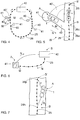
- FIG. 1 shows a mining vehicle 1, in this case a loading vehicle, which is a special type of wheel loader comprising a bucket 2 at its front end for transporting and loading excavated rock material.
- the loading vehicle may be frame-steered, whereby it is provided with a centre pivot 3 between a front frame 4 and a rear frame 5.
- Such an articulated loading vehicle is steered by turning the frame parts relative to each other by means of steering cylinders 6, for example.
- the frame parts include wheels 7, which are not turned relative to the frame parts.
- the mining vehicle 1 is further provided with a control system which includes one or more control units 8 configured to control actuators in the mining vehicle for controlling and driving the vehicle.
- the control unit 8 is arranged to control for example the steering cylinders 6 and a traction system 9 including a drive motor 10 and transmission means 11.
- the mining vehicle can be driven in forward direction F and in reverse direction R.
- the control unit 8 may be a computer equipped with appropriate software, or an entity consisting of a plurality of computers.
- the mining vehicle may be provided with a data transfer unit 12 which enables the control unit 8 to establish a data transfer connection with one or more control units 13 external to the mining vehicle.
- the data transfer connection may be based on a wireless connection provided by one or more base stations 14.
- the external control 13 unit may reside in a control room 15, which may be arranged outside the mine.
- the control system of the mining vehicle 1 comprises a positioning system or positioning unit.
- the positioning system may comprise one or more scanners 16 for scanning the space surrounding the mining vehicle and the geometry of that space.
- the scanners 16 may be laser scanners, ultrasound scanners or any other type of scanner suitable for determining a profile and surface contours of the surrounding mine walls.
- the scanning results are compared to an environmental model of the mine that is created in advance.
- the positioning system which is based on the environmental model, can be used to determine the current position and orientation of the mining vehicle. Further, this positioning principle can be used for determining the distance travelled by the mining vehicle 1.
- the driving distance is measured by an arrangement where one or more sensors 17 are used for measuring the rotation of a wheel 7 or transmission means.
- the positioning system determines the rotational movement of the wheel and then calculates the magnitude of distance travelled by the machine.
- the mining vehicle 1 may comprise a gyroscope or corresponding measuring device 18 for determining the orientation of the mining vehicle.
- the mining vehicle 1 may be provided with a video image system allowing visual information to be sent from the unmanned mining vehicle 1 to the control room 15 for an operator 20. Some mining tasks, such as loading of the bucket are quite difficult to automate and manual control via teleoperation is still widely used.
- the mining vehicle 1 may comprise one or more video cameras 21 and video data is sent via the data transfer unit 12 to the control room 15. In the control room 15, there may be one or more displays 22 for showing video image of the operation, and control means 23, such as joy-sticks for controlling the traction system 9 and actuators, such as bucket cylinders 24.
- the mining vehicle may comprise one or more measuring devices, sensors or other detection means for helping the remote control during the manual operation.
- an articulated loading vehicle 1 is driving in a mine along a pre-determined and stored main route 25 under automatic drive N.
- the route 25 includes route points 26a - 26c at determined intervals.
- the route points 26 include position data, such as coordinates in a coordinate system of the mine. Other route-point-specific data can also be included.
- the loading vehicle 1 may autonomously follow the route 25 by following the position information of the route points 26 and simultaneously determining the current position by comparing the measuring data of scanners 16 and the pre-stored environment model.
- the front part 4 and rear part 5 are turned around the centre pivot 3, whereby different steering angles T occur.
- the environment model generally refers to a model modelling the mine and may have been defined by driving a scouting or measuring vehicle in the mine and by scanning wall profiles, for example.
- the environment model comprises at least data concerning the location of the walls 27 of a tunnel.
- the environment model may determine x and y coordinates of the points describing the location of the walls 27 in a particular standard system of coordinates.
- the x and y coordinates determine the location of a wall 27 at a height at which the scanner 16 resides in the mining machine 1.
- a two-dimensional tunnel map is provided by outputting the points of the environment model on a xy plane.
- the environment model may also comprise other information if necessary. Should a three-dimensional scanning be used, the environment model could further comprise z coordinate information, in which case a 3D profile of the tunnels would be available.
- FIG 3 illustrates an apparatus 28 according to an embodiment for determining drive paths for mining vehicles.
- the apparatus 28 comprises at least a drive path generator 29 for determining drive paths by utilizing an environment model 30 and a kinematic model 31.
- the drive path generator 29 executes at least one drive path search algorithm which searches for feasible steering sequences satisfying a collision-free drive of the mining vehicle.
- the generator 29 may be implemented e.g. by a general-purpose processor of a data processing device, on which one or more computer programs executing drive path search determination procedures are run.
- the computer program comprises a code for executing at least some of the features related to creating steering sequences already described and illustrated in the following in connection with Figures 4 to 9 .
- the computer program may be recorded on non-transitory computer-readable media including program instructions for implementing various operations executed by a computer.
- the apparatus 28 may retrieve the kinematic model of the mining vehicle, stored in a data file or memory, or alternatively the kinematic model or data may be included in a vehicle-specific search algorithm. By means of an input device, it is possible to determine for example a goal point for the path search, or alternatively the search algorithm selects the goal point according to defined rules. Data concerning position and orientation of the mining vehicle can be transmitted from one or more measuring devices 33 to the drive path generator 29.
- the drive path search process 34 may further include pre-defined rules for the search or one or more decision tree 35.
- a collision avoidance process 36 is also employed and it may rely on an occupancy grid 37.
- the path generator 29 experiments on a plurality of steering movements and finds one or more steering sequences implementing a collision-free drive path.
- the created driving sequences can be tested, and visualized for the operator, in a simulation unit 38 before selecting one single sequence to be executed.
- the selected driving sequence can be stored in a memory unit 39, which can be a transient memory.
- the stored steering sequence can be read by the control unit 8 of the mining vehicle when driving automatically along the created drive path. Let it be mentioned that the drive path generator 29 and the control unit 8 can be separate devices or they can be integrated.
- Figure 4 shows a principle of an automated transport system in a block caving mine and the utilization of the drive path search process in such a system.
- One or more automatic loading vehicles 1 are driven along a main route 25 comprising route points 26 provided with position data.
- the loading vehicle 1 is driven under manual control M from the main route 25 to the loading tunnel 40 to load a bucket.
- the position and orientation of the loading vehicle is determined and input as initial data to a drive path generator.
- a steering sequence is created before starting a return drive.
- the loading vehicle 1 can be reverse driven automatically N according to the generated steering sequence back to the main route 25.
- the loading vehicle 1 When the loading vehicle 1 has returned to the main route 25, it can continue in automatic drive to an unloading site 42 to empty the bucket. Thereafter the loading vehicle 1 drives automatically close to the same or another loading tunnel 40. Again the operator takes control of the loading vehicle 1 and drives it under remote control to the loading site 41 and fills the bucket. After this a new unique steering sequence is generated for driving the loading vehicle automatically back to the main route 25.
- Figure 5 shows in detail the driving of the loading vehicle 1 manually M from the main route 25 via the loading tunnel 40 to the loading site 41 and its return back to the main route 25 by reverse driving it according to the created steering sequence.
- the actual initial position and orientation of the loading vehicle 1 is defined as a start point A for a drive path.
- the operator may select one route point 26c of the main route 25 to represent a goal point B for the drive path.
- the path search algorithm may define the goal point B on the main route 25.
- FIGS 4 and 5 broken lines show an alternative branching tunnel 40' along which the loading vehicle 1 may return drive back to the main route 25.
- one route point 26i is determined as a goal point B'.
- Figure 6 discloses a mine, wherein a mine vehicle, such as a loading vehicle, can be driven automatically between two mining work points, such as a loading site 41 and an unloading site 42.
- the loading vehicle can be driven under teleoperation in the loading site 41 and when a bucket filling procedure is completed, an actual initial position and orientation of the vehicle is determined.
- a start point A for the drive path search is defined.
- Predetermined position data of the unloading site 42 can be used as a goal point B for the search process.
- a steering sequence is created in a processor for enabling the automatic driving from point A to point B.
- the mining vehicle can be driven from the unloading site 42 to the loading site 41 along a predetermined route 25. It is also possible to generate a single-use drive path for driving the loading vehicle from the unloading site 42 to the loading site 41, whereby there is no need for the main route 25.
- a mining vehicle 1 has diverged from a main route 25 and the automatic drive is ended.
- the mining vehicle 1 needs to be returned to the main route 25.
- a return drive path is generated for returning the mining vehicle 1 to the main route 25.
- An actual position and orientation of the vehicle is determined and this data is employed as a start point A for the return drive path search.
- a route point 26h recognized before the diverged drive can be selected as a goal point B.
- any other route point of the main route 25 can be selected as the goal point B.
- Figure 8 is a simplified chart showing a drive path search procedure in general. The steps and features presented in this Figure are discussed above and especially in section Brief description of the invention.
- Figure 9 is also a simplified chart that shows issues relating to a return path search procedure. The steps and features presented in this Figure are discussed above and especially in section Brief description of the invention and in connection with Figures 4, 5 and 7 .
- Figure 10 discloses an example of a decision tree 35 in which steps are pre-determined for experimenting on different steering and driving possibilities. Thanks to the decision tree 35, the most probable steering movements are tested first, which fastens the path search.
- the decision tree 35 may include a basic steering block 44 which includes steering possibilities that occur in most driving situations.
- the decision tree 35 comprises several branches and decisions are made in knot points 45, which are shown as black points.
- the decision tree 35 is followed from top to bottom and from left to right. At first experiments are made according to steering actions in the left-most basic steering block 44 and if no solution is found, then there is a need for corrective actions. In the right-most branch, driving direction is changed, for example.
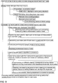
- FIG 11 illustrates a two-dimensional occupancy grid 37 of a mine.
- the occupancy grid may be used for collision avoidance monitoring. It has been noted that an occupancy grid can quicken the collision examination significantly and it also does not require extensive computing capacity.
- the occupancy grid 37 can be formed for a limited area of the mine, whereby occupancy grids can be formed for each loading tunnel 40 in the block caving system disclosed in Figures 4 and 5 . By limiting the examined mining are it is possible to further quicken the collision analysis.
- the occupancy grid 37 can be formed on the basis of an environment model of the mine.
- the mine or the selected limited mine area can be defined in cells, the size of which may be a few centimetres. Cells of two types are used for defining the mine, namely free cells and occupied cells.
- Free cells are located in a free space and occupied cells are located inside rock.
- white colour areas show the free cells 47 and grey colour areas show the occupied cells 48.
- Contour lines of the walls 27 are also defined as occupied areas.
- the collision avoidance system checks whether the mining vehicle enters into a cell occupied by rock material or not.
- Several collision control points can be defined according to the outer dimensions of the mining vehicle and the collision avoidance system may check that these points stay outside the occupied cells when the mining vehicle drives along a drive path. It is also possible to define one or more security zones around the mining vehicle, whereby the collision avoidance system may check that the safe zone remains in the acceptable area 47 defined by the free cells.
- FIGs 12 to 14 are schematic simulation views showing how a mining vehicle 1 is driven along a selected driving path according to a created driving sequence.
- the driving sequence is illustrated as graph 49.
- the steering sequence defines steering movements as a function of the driving distance.
- the steering movements can also be defined as steering angles of the centre pivot 3.
- the current control stages are shown by black squares and arrows. Movements of the mining vehicle can be shown as ghost lines in the simulation views.
- the computer program disclosed in this patent application may be recorded in non-transitory computer-readable media including program instructions to implement various operations embodied by a computer.
- the media may also include, alone or in combination with the program instructions, data files, data structures, and the like.
- Examples of computer-readable media or computer-readable storage devices include magnetic media, such as hard disks, and optical media such as CR-ROM disks and DVDs, flash memory means, and hardware devices that are configured to store software.
- the computer-readable media may be a plurality of computer-readable storage devices in a distributed network, so that the program instructions are stored in a plurality of computer-readable storage devices and executed in a distributed fashion.
- the program instructions may be executed by one or more processors or processing devices.
Abstract
Description
- The invention relates to an automatic drive of a mining vehicle in a mine, and particularly to searching for in a data processing device a drive path for the automatic drive of a mining vehicle from a start point to a goal point in a mine.
- The invention further relates to a method for finding a drive path for a mining vehicle in a mine.
- The field of the invention is defined more specifically in the preambles of the independent claims.
- In mines, various mining vehicles, i.e. mobile mining machines, are used. Typical mining vehicles are rock drilling rigs, bolting vehicles, charging devices, loading vehicles, transport vehicles and measuring vehicles. In an automated mine, these vehicles can be unmanned and they can be driven automatically along a predetermined route in a mine. The mining vehicle is provided with means to determine the current location. When the automated mining vehicle is driven off the route, it may be difficult to return the vehicle back to the route.
- An object of the invention is to provide a novel and improved apparatus and method for finding a drive path for an automatic drive of a mining vehicle in a mine.
- The mining vehicle according to the invention is characterized in that the apparatus is configured to: receive data on actual initial position and orientation of the mining vehicle in the mine and input this data as the start point of the drive path; experiment on several different steering movements of the mining vehicle relative to the driving movements to find at least one steering sequence satisfying a collision-free drive path from the start point to the goal point; and select one created steering sequence for executing the found drive path completely.
- The method according to the invention is characterized by receiving actual initial position and orientation data of the mining vehicle in the mine and feeding this data as the start point for the drive path; experimenting on several different steering movements of the mining vehicle relative to the driving movements to find at least one steering sequence satisfying a collision-free drive path from the start point to the goal point; and selecting one created steering sequence for executing the found drive path completely.
- An idea of the disclosed solution is that a single-use drive path is generated for a mining vehicle. A start point for the drive path to be formed is defined by determining an actual initial position and orientation of the mine vehicle in the mine. As a goal or target point for the drive path, one predetermined point in the mine is determined. The goal point includes at least position data. The drive path is generated in a path generator including at least one processor wherein a path search process, or algorithm, is implemented. The path search process employs a kinematic model of the mining vehicle and an environment model of the mine and searches for feasible collision-free drive paths between the starting point and the goal point. In the drive path search process, several different steering movements relative to driving movements are experimented on in order to find one or more drive path steering sequences allowing a collision-free drive to the chosen goal point in the mine. A collision avoidance examination is applied. As a result of the path search, at least one complete steering sequence is formed in advance for the drive. The created steering sequence defines steering movements as a function of the driving distance. When executing the steering sequence, the distance driven is determined by measuring means of the mining vehicle.
- An advantage of the disclosed solution is that a drive path is generated for each specific situation, which means that the drive path is of a single-use type. This way, the drive path is always generated by taking into account the accurate initial position and orientation of the mining vehicle. The generated and accepted drive path is reliable, because the drive path is completely formed before the mining vehicle executes the drive. Thus, any difficulties are taken into account already before the start of the drive and no interruptions occur during the drive. One more benefit is that the steering sequence of the drive path determines the steering movements as a function of distance, whereby the driving speed does not affect the control of the drive. This simplifies the control procedure. In the disclosed solution, the drive path can be defined without creating any route points provided with position data, such as coordinates.
- According to an embodiment, a steering sequence is generated for driving a mining vehicle in a mine automatically from a first mine work point to a second mine work point. In the first mine work point, the mining vehicle is operated under manual control and when the operator has completed the manual operations, the path search algorithm is started. The mining vehicle may have a random initial position and orientation after the manual operations. The mining vehicle can be transfer driven from the first mine work point to the second work point by executing the created steering sequence in a control unit of the mining vehicle. The mining vehicle may be a loading vehicle, which is arranged to drive in the mine between a loading point and an unloading point. Loading a bucket of the loading vehicle is a demanding task and difficult to automate. Therefore, the bucket may be filled by driving the vehicle towards a rock pile manually and simultaneously controlling the movements of the bucket manually. After the bucket has been filled, the manual operation can be stopped and the path search algorithm can be started. The path search process determines the initial position and orientation of the mining vehicle at the loading point, whereby a start point is defined. As a goal point for the search, pre-determined position data of the unloading point is used. On the basis of the start point location and orientation, goal point position data, a mining vehicle specific kinematic model and an environment model of the mine, the path search algorithm creates a single-use steering sequence before starting the transfer drive. Thus, the loading vehicle can be driven under automatic control from the rock pile or loading chute to the unloading chute or conveying system without needing a pre-determined route.
- According to an embodiment, the mining vehicle is arranged to drive in the mine automatically along a pre-determined main route including a plurality of route points. The mine vehicle moves away from the main route and is then returned back to the main route in order to continue the automatic main drive. In order to automatically drive the mine vehicle back to the main route a single-use return path is generated and selected before the return drive is started. In this embodiment, one route point of the main route is selected as a goal point for the return path. The selected route point includes position data.
- According to an embodiment, the mining vehicle is driven intentionally away from the main route in order to perform mining work in a mining work area located outside the main route. The mining vehicle can be driven to the mining work area under the control of an operator. The operator may drive the mining vehicle under remote control from a control room located outside the mine, whereby the control commands are transmitted to the control unit of the mine vehicle via data communication means and the operator is provided with visual data of the mining work area. The mining vehicle may also include sensors and measuring devices for producing further information for the manual drive. The mining vehicle is provided with a teleoperation mode for the manual drive. The automatic return drive releases the operator for other tasks.
- According to an embodiment, the control system is arranged to return the mining vehicle back to the pre-determined main route when the mining vehicle has unexpectedly diverged from the route. Such a situation may occur as a result of malfunction in the navigation system or automatic drive controlling system of the mining vehicle, or possibly also when executing sudden steering movements in order to avoid collision with other mining vehicles or collapsed or dropped rock blocks. Thanks to this embodiment the mining vehicle can be restored to the main route for continuing the automatic production drive after an unexpected incident. This improves the operational reliability of the automatic mining system.
- According to an embodiment, the disclosed system is intended for underground mines having tunnels and other rock caverns where the mine vehicles can be driven for executing pre-determined mine work in mine working areas. The mine vehicles can be driven along the main route for transport or production drive.
- According to an embodiment, the disclosed system is used in block caving where ore body is undercut and the ore caves naturally downwards a vertical rise. In this method gravitational flow of ore is utilized. The mine vehicle is a loading vehicle which is driven under manual control from the main route to a branching loading tunnel for loading a bucket and is thereafter reverse driven automatically according to the generated steering sequence back to the main route.
- According to an embodiment, the path generation algorithm is intended for a short driving distance. The length of the drive path is typically less than 100 meters. When the mine vehicle diverges from a main route, the return route may be only 10 to 40 meters.
- According to an embodiment, rock surfaces around the mining vehicle are scanned and the scanning data is compared with an environment model of the mine when determining the distance driven during the return drive. A benefit of this type of distance measurement is that a possible slippage of the wheels and an uneven driving surface have no influence on the measurement accuracy. This allows exact steering movements during the drive along the generated path.
- According to an embodiment, a route is generated on the basis of the generated drive path steering sequence. The route includes several route points at an interval from each other. Each route point includes position data, such as coordinates in a coordinate system. Contrary to the route, the driving sequence does not define any route points provided with coordinate data.
- According to an embodiment, the drive path steering sequence is stored only into a short-term memory since the sequence is for single-use purpose only. The steering sequence may be deleted from the memory after being executed by the control unit of the mining vehicle. The steering sequence may be stored temporarily in a transient computer-readable memory.
- According to an embodiment, the goal point is determined by the operator and is then input into the drive path searching process.
- According to an embodiment, the data relating to the goal point includes data on the final orientation of the mining vehicle. This way, it is possible to drive the mining vehicle so that the succeeding automatic driving can be started smoothly.
- According to an embodiment, the goal point is determined by the drive path search algorithm, which may include a control strategy or rules to select the goal point among pre-determined points. The search algorithm may update the selection of the goal point during the search process. This way, the search process may be started with a first goal point or target group of goal points, but can be changed to a second goal point when the algorithm determines during the path generation process, that by selecting the second goal point a better end result can be achieved. The update of the goal point may allow a better final orientation of the mining vehicle to be achieved, for example.
- According to an embodiment, an initial position and orientation of the mining vehicle are determined by one or more measuring devices arranged in the mining vehicle.
- According to an embodiment, at least an initial position, and possibly also the orientation, of the mining vehicle is determined by scanning the surrounding wall surfaces of the mine and comparing the results with a pre-stored environment model. This way, the start point for the return path is determined without fixed infrastructure and is based on surface profiles or contours of the mine.
- According to an embodiment, an initial orientation of the mining vehicle is defined by means of a gyroscope or similar measuring device.
- According to an embodiment, an initial position and orientation of the mining vehicle are determined by one or more measuring devices arranged external to the mining vehicle. The measuring device can be arranged at a mining work point, such as a loading point, and measuring data can be communicated to the drive path generator by means of a data communication device.
- According to an embodiment, the drive path search algorithm employs a mine vehicle-specific kinematic model, referring generally to data representing kinematic properties of the mining vehicle, which may be formed in advance. Depending on the operational principle and type of the mining vehicle, outer dimensions, layout and steering principle and mechanism, for example, a kinematic model is created for the mine vehicles included in the automatic control system. In principle, a kinematic model can be formed for all kinds of mining vehicles. Thus, the disclosed path search procedure can be applied widely for different mine vehicles having specific kinematic models.
- According to an embodiment, the drive path search algorithm retrieves a mine vehicle specific kinematic model or kinematic data which is formed in advance and stored in a data file.
- According to an embodiment, a mine vehicle-specific kinematic model or kinematic data is formed in advance and is included in the drive path search algorithm.
- According to an embodiment, the environment model is pre-formed, and is stored in at least one memory device or media. The path search apparatus retrieves the environment model, and employs it when generating a drive path. The environment model can be defined by driving a scouting or measuring vehicle in the mine, and by scanning wall profiles simultaneously.
- According to an embodiment, the environment model is formed by means of scanners or other suitable measuring devices of the mining vehicle before starting the search algorithm. This embodiment can be applied in situations, where the distance between the start point and the goal point is relatively short and visibility is good. Thus, in this embodiment, there is no need to retrieve any pre-formed environment model from a memory.
- According to an embodiment, the mining vehicle is a loading vehicle, which is a special type of a wheel loader comprising a bucket at its front end for transporting and loading excavated rock material. Further, the loading vehicle is frame-steered, whereby it is provided with a front frame and a rear frame and a centre pivot between the frame parts. Such a loading vehicle is steered by turning the frame parts relative to each other by means of steering cylinders, for example. The frame parts include wheels which are not turned relative to the frame parts. A kinematic model is formed for such a frame-steered articulated loading machine. The steering sequence of the frame-steered mining vehicle may define steering angles of the centre pivot relative to the driving distance.
- According to an embodiment, the mining vehicle is a rock drilling rig, bolting vehicle, charging vehicle, transport vehicle or measuring vehicle.
- According to an embodiment, the path search process employs predetermined rules for the testing of different steering movements. These rules may decrease the number of different steering movements to be tested during the search, whereby the process is quickened. The rules may take into account known information relating to the driving situation. For example, the rules may include information concerning the transfer drive away from the main route, whereby the steering direction is known by the system. Moreover, when experimenting with the steering movements, the algorithm may prioritize such steering movements which have been detected to have high frequency of occurrence before.
- According to an embodiment, the path search process employs a decision tree wherein pre-determined steps for the testing of different steering steps are defined beforehand on the basis of known features of the driving situation. In the decision tree, the most probable steering movements are tested first, which fastens the path search. Different decision trees may be formed in advance for different situations, and these decision trees may be stored in a data file which can be retrieved by the search algorithm. The decision tree illustrates the search procedure well, and it is easy to modify the decision tree case-specifically when needed.
- According to an embodiment, the path search process experiments on different steering movements in random. This embodiment requires sufficient computing capacity in order to offer a fast path search.
- According to an embodiment, the collision avoidance system employs an occupancy grid, wherein an occupancy grid map of the mine is generated. The occupancy grid maps the environment as an array of cells. The cell size may be a few centimetres typically ranging from 1 to 10 cm. The mine map is in 2D. The mine may be divided into two types of cells, namely free cells that are in a free space, such as in a tunnel, and occupied cells that are in rock. The collision avoidance system checks whether the mining vehicle protrudes into a grid cell occupied by rock material or not. Thus, the use of the occupancy grid is a kind of binary problem, whereby it offers a possibility to a fast collision avoidance examination and does not need extensive data processing capacity.
- According to an embodiment, the steering sequence is executed without simultaneous navigation. This is possible since the path drive is based on complete steering and driving instructions formed in advance. Thanks to this feature, the automatic drive can be fast, since there is no need for extensive calculations and measurements during the drive. Thus, it may be sufficient for the control of the automatic drive to measure only the distance being driven along the generated path. One additional advantage is that conditions on the drive route have only a minor effect on the automatic drive. For example, spreading dust after loading does not hamper the execution of the created steering sequence, since there is no need to scan the surroundings of the mining vehicle in order to navigate along the drive path.
- According to an embodiment, the steering sequence may include one or more changes of driving direction. This feature facilitates the drive path generation when there are very narrow spaces and difficult driving situations.
- According to an embodiment, the path search algorithm finds several acceptable collision-free steering sequences, from which one is selected on the basis of pre-determined rules and criteria. One possible criterion for the selection may be simplicity of the steering sequence, whereby steering sequences without changes of driving direction may have higher priority in the selection. Another possible criterion for the selection may be the distance between the mining vehicle and the wall surfaces. The distance information can be calculated in the processor. The greater the distance to the walls is, the safer is the drive, wherefore a steering sequence producing a greater wall distance may be prioritized. One possibility is to minimize the time of the return drive and to select a driving sequence that offers the shortest or fastest return drive.
- According to an embodiment, the path search algorithm indicates if no return path can be found without collision to the wall surfaces. In such as case, manual drive is needed for changing the initial position. The operator drives the mining vehicle to a new place and orientation, after which the path search algorithm is restarted.
- According to an embodiment, a loading point, an unloading point or any other mining work point is provided with a pre-determined initial area. The operator may drive the mining vehicle to the initial area after the mining work has been completed in the mining work point. The initial area is determined so, that the mining vehicle can be driven away from the mining work point without instant problems. This means that, when being in the initial area, the search algorithm can find a drive path for automatic driving. Exact data on position and orientation of the start point is determined before beginning the search algorithm, of course.
- According to an embodiment, the return path is generated to the same mine space where the mining vehicle diverged from its route.
- According to an embodiment, the return path is generated to a different mine space as where the mining vehicle diverged from its route.
- According to an embodiment, the return drive is executed predominantly by reverse driving the mining vehicle.
- According to an embodiment, the goal point in the return path search is a route point of the main route which is located closest to the mining vehicle before the mining vehicle diverged from the main route.
- According to an embodiment, the goal point in the return path search is a route point of the main route which is located closest to the mining vehicle.
- According to an embodiment, the drive path search method, apparatus and software disclosed in this patent application are used for finding a drive path for a surface mining vehicle operating in an opencast mine or similar mining working site above ground. The path search may be implemented by using the same search processes disclosed above.
- Some embodiments are described in more detail in the accompanying drawings, in which
-
Figure 1 is a schematic side view showing a mining vehicle, -
Figure 2 is a schematic top view illustrating an arrangement for driving an articulated loading vehicle in a mine along a main route, -
Figure 3 illustrates a control block diagram of an apparatus planning a drive path of a mining vehicle, -
Figure 4 is a schematic view showing a principle of an automated transport system in a block caving mine and the utilization of the drive path search process in such system, -
Figure 5 is a schematic top view of a detail W inFigure 4 showing a loading tunnel branching from a main route, -
Figure 6 is a schematic view showing a mine, where a mine vehicle is driven automatically between two mining work points and a steering sequence is created for enabling the drive, -
Figure 7 is a schematic top view showing a mining vehicle diverged from a main route and possibilities for returning the mining vehicle back to the route, -
Figure 8 is a simplified chart showing a drive path search procedure in a general concept, -
Figure 9 is a simplified chart showing issues relating to a return path search procedure, -
Figure 10 illustrates a decision tree defining pre-determining steps for experimenting on different steering and driving possibilities, -
Figure 11 illustrates an occupancy grid of a mine, and -
Figures 12 to 14 are schematic simulation views showing the driving of a mining vehicle along a selected driving path according to a created driving sequence. - For the sake of clarity, the figures show some embodiments of the disclosed solution in a simplified manner. In the figures, like reference numerals identify like elements.
-
Figure 1 shows amining vehicle 1, in this case a loading vehicle, which is a special type of wheel loader comprising abucket 2 at its front end for transporting and loading excavated rock material. The loading vehicle may be frame-steered, whereby it is provided with acentre pivot 3 between afront frame 4 and arear frame 5. Such an articulated loading vehicle is steered by turning the frame parts relative to each other by means of steeringcylinders 6, for example. The frame parts includewheels 7, which are not turned relative to the frame parts. Themining vehicle 1 is further provided with a control system which includes one or more control units 8 configured to control actuators in the mining vehicle for controlling and driving the vehicle. The control unit 8 is arranged to control for example thesteering cylinders 6 and atraction system 9 including adrive motor 10 and transmission means 11. The mining vehicle can be driven in forward direction F and in reverse direction R. The control unit 8 may be a computer equipped with appropriate software, or an entity consisting of a plurality of computers. - The mining vehicle may be provided with a
data transfer unit 12 which enables the control unit 8 to establish a data transfer connection with one ormore control units 13 external to the mining vehicle. The data transfer connection may be based on a wireless connection provided by one ormore base stations 14. Theexternal control 13 unit may reside in acontrol room 15, which may be arranged outside the mine. - Further, the control system of the
mining vehicle 1 comprises a positioning system or positioning unit. The positioning system may comprise one ormore scanners 16 for scanning the space surrounding the mining vehicle and the geometry of that space. Thescanners 16 may be laser scanners, ultrasound scanners or any other type of scanner suitable for determining a profile and surface contours of the surrounding mine walls. The scanning results are compared to an environmental model of the mine that is created in advance. The positioning system, which is based on the environmental model, can be used to determine the current position and orientation of the mining vehicle. Further, this positioning principle can be used for determining the distance travelled by themining vehicle 1. According to an alternative, the driving distance is measured by an arrangement where one ormore sensors 17 are used for measuring the rotation of awheel 7 or transmission means. On the basis of the measurement data, the positioning system determines the rotational movement of the wheel and then calculates the magnitude of distance travelled by the machine. Further, themining vehicle 1 may comprise a gyroscope or corresponding measuringdevice 18 for determining the orientation of the mining vehicle. - The
mining vehicle 1 may be provided with a video image system allowing visual information to be sent from theunmanned mining vehicle 1 to thecontrol room 15 for anoperator 20. Some mining tasks, such as loading of the bucket are quite difficult to automate and manual control via teleoperation is still widely used. Themining vehicle 1 may comprise one ormore video cameras 21 and video data is sent via thedata transfer unit 12 to thecontrol room 15. In thecontrol room 15, there may be one ormore displays 22 for showing video image of the operation, and control means 23, such as joy-sticks for controlling thetraction system 9 and actuators, such asbucket cylinders 24. In addition to cameras, the mining vehicle may comprise one or more measuring devices, sensors or other detection means for helping the remote control during the manual operation. - In
Figure 2 an articulatedloading vehicle 1 is driving in a mine along a pre-determined and storedmain route 25 under automatic drive N. Theroute 25 includesroute points 26a - 26c at determined intervals. The route points 26 include position data, such as coordinates in a coordinate system of the mine. Other route-point-specific data can also be included. Theloading vehicle 1 may autonomously follow theroute 25 by following the position information of the route points 26 and simultaneously determining the current position by comparing the measuring data ofscanners 16 and the pre-stored environment model. Thefront part 4 andrear part 5 are turned around thecentre pivot 3, whereby different steering angles T occur. - The environment model generally refers to a model modelling the mine and may have been defined by driving a scouting or measuring vehicle in the mine and by scanning wall profiles, for example. The environment model comprises at least data concerning the location of the
walls 27 of a tunnel. The environment model may determine x and y coordinates of the points describing the location of thewalls 27 in a particular standard system of coordinates. When generating an environment model by scanning, the x and y coordinates determine the location of awall 27 at a height at which thescanner 16 resides in themining machine 1. In the case of one plane, a two-dimensional tunnel map is provided by outputting the points of the environment model on a xy plane. The environment model may also comprise other information if necessary. Should a three-dimensional scanning be used, the environment model could further comprise z coordinate information, in which case a 3D profile of the tunnels would be available. -
Figure 3 illustrates anapparatus 28 according to an embodiment for determining drive paths for mining vehicles. Theapparatus 28 comprises at least adrive path generator 29 for determining drive paths by utilizing anenvironment model 30 and akinematic model 31. Thedrive path generator 29 executes at least one drive path search algorithm which searches for feasible steering sequences satisfying a collision-free drive of the mining vehicle. Thegenerator 29 may be implemented e.g. by a general-purpose processor of a data processing device, on which one or more computer programs executing drive path search determination procedures are run. The computer program comprises a code for executing at least some of the features related to creating steering sequences already described and illustrated in the following in connection withFigures 4 to 9 . The computer program may be recorded on non-transitory computer-readable media including program instructions for implementing various operations executed by a computer. Theapparatus 28 may retrieve the kinematic model of the mining vehicle, stored in a data file or memory, or alternatively the kinematic model or data may be included in a vehicle-specific search algorithm. By means of an input device, it is possible to determine for example a goal point for the path search, or alternatively the search algorithm selects the goal point according to defined rules. Data concerning position and orientation of the mining vehicle can be transmitted from one ormore measuring devices 33 to thedrive path generator 29. The drivepath search process 34 may further include pre-defined rules for the search or one ormore decision tree 35. Acollision avoidance process 36 is also employed and it may rely on anoccupancy grid 37. Thepath generator 29 experiments on a plurality of steering movements and finds one or more steering sequences implementing a collision-free drive path. The created driving sequences can be tested, and visualized for the operator, in asimulation unit 38 before selecting one single sequence to be executed. The selected driving sequence can be stored in amemory unit 39, which can be a transient memory. The stored steering sequence can be read by the control unit 8 of the mining vehicle when driving automatically along the created drive path. Let it be mentioned that thedrive path generator 29 and the control unit 8 can be separate devices or they can be integrated. -
Figure 4 shows a principle of an automated transport system in a block caving mine and the utilization of the drive path search process in such a system. One or moreautomatic loading vehicles 1 are driven along amain route 25 comprising route points 26 provided with position data. There areseveral loading tunnels 40 branching from themain route 25 and comprisingloading sites 41. Theloading vehicle 1 is driven under manual control M from themain route 25 to theloading tunnel 40 to load a bucket. When the loading is complete, the position and orientation of the loading vehicle is determined and input as initial data to a drive path generator. A steering sequence is created before starting a return drive. Theloading vehicle 1 can be reverse driven automatically N according to the generated steering sequence back to themain route 25. When theloading vehicle 1 has returned to themain route 25, it can continue in automatic drive to anunloading site 42 to empty the bucket. Thereafter theloading vehicle 1 drives automatically close to the same or anotherloading tunnel 40. Again the operator takes control of theloading vehicle 1 and drives it under remote control to theloading site 41 and fills the bucket. After this a new unique steering sequence is generated for driving the loading vehicle automatically back to themain route 25. -
Figure 5 shows in detail the driving of theloading vehicle 1 manually M from themain route 25 via theloading tunnel 40 to theloading site 41 and its return back to themain route 25 by reverse driving it according to the created steering sequence. The actual initial position and orientation of theloading vehicle 1 is defined as a start point A for a drive path. The operator may select oneroute point 26c of themain route 25 to represent a goal point B for the drive path. Alternatively, the path search algorithm may define the goal point B on themain route 25. - In
Figures 4 and 5 broken lines show an alternative branching tunnel 40' along which theloading vehicle 1 may return drive back to themain route 25. In this case, oneroute point 26i is determined as a goal point B'. In this embodiment, there is no need to drive the mining vehicle in reverse direction when returning back to themain route 25. -
Figure 6 discloses a mine, wherein a mine vehicle, such as a loading vehicle, can be driven automatically between two mining work points, such as aloading site 41 and anunloading site 42. The loading vehicle can be driven under teleoperation in theloading site 41 and when a bucket filling procedure is completed, an actual initial position and orientation of the vehicle is determined. Thus, a start point A for the drive path search is defined. Predetermined position data of theunloading site 42 can be used as a goal point B for the search process. A steering sequence is created in a processor for enabling the automatic driving from point A to point B. The mining vehicle can be driven from the unloadingsite 42 to theloading site 41 along apredetermined route 25. It is also possible to generate a single-use drive path for driving the loading vehicle from the unloadingsite 42 to theloading site 41, whereby there is no need for themain route 25. - In
Figure 7 amining vehicle 1 has diverged from amain route 25 and the automatic drive is ended. In order to resume the automatic drive, themining vehicle 1 needs to be returned to themain route 25. A return drive path is generated for returning themining vehicle 1 to themain route 25. An actual position and orientation of the vehicle is determined and this data is employed as a start point A for the return drive path search. Aroute point 26h recognized before the diverged drive can be selected as a goal point B. Alternatively, any other route point of themain route 25 can be selected as the goal point B. When aroute point 26p is selected, there is no need to reverse drive R the mining vehicle, but instead themining vehicle 1 can be returned by driving it in forward direction F whereby the vehicle moves towards the original transport direction. This saves time and is effective. -
Figure 8 is a simplified chart showing a drive path search procedure in general. The steps and features presented in this Figure are discussed above and especially in section Brief description of the invention. -
Figure 9 is also a simplified chart that shows issues relating to a return path search procedure. The steps and features presented in this Figure are discussed above and especially in section Brief description of the invention and in connection withFigures 4, 5 and 7 . -
Figure 10 discloses an example of adecision tree 35 in which steps are pre-determined for experimenting on different steering and driving possibilities. Thanks to thedecision tree 35, the most probable steering movements are tested first, which fastens the path search. Thedecision tree 35 may include abasic steering block 44 which includes steering possibilities that occur in most driving situations. Thedecision tree 35 comprises several branches and decisions are made in knot points 45, which are shown as black points. Thedecision tree 35 is followed from top to bottom and from left to right. At first experiments are made according to steering actions in the left-mostbasic steering block 44 and if no solution is found, then there is a need for corrective actions. In the right-most branch, driving direction is changed, for example. -
Figure 11 illustrates a two-dimensional occupancy grid 37 of a mine. In the drive path search process, the occupancy grid may be used for collision avoidance monitoring. It has been noted that an occupancy grid can quicken the collision examination significantly and it also does not require extensive computing capacity. Theoccupancy grid 37 can be formed for a limited area of the mine, whereby occupancy grids can be formed for eachloading tunnel 40 in the block caving system disclosed inFigures 4 and 5 . By limiting the examined mining are it is possible to further quicken the collision analysis. Theoccupancy grid 37 can be formed on the basis of an environment model of the mine. The mine or the selected limited mine area can be defined in cells, the size of which may be a few centimetres. Cells of two types are used for defining the mine, namely free cells and occupied cells. Free cells are located in a free space and occupied cells are located inside rock. InFigure 11 , white colour areas show thefree cells 47 and grey colour areas show theoccupied cells 48. Contour lines of thewalls 27 are also defined as occupied areas. The collision avoidance system checks whether the mining vehicle enters into a cell occupied by rock material or not. Several collision control points can be defined according to the outer dimensions of the mining vehicle and the collision avoidance system may check that these points stay outside the occupied cells when the mining vehicle drives along a drive path. It is also possible to define one or more security zones around the mining vehicle, whereby the collision avoidance system may check that the safe zone remains in theacceptable area 47 defined by the free cells. -
Figures 12 to 14 are schematic simulation views showing how amining vehicle 1 is driven along a selected driving path according to a created driving sequence. The driving sequence is illustrated asgraph 49. The steering sequence defines steering movements as a function of the driving distance. When themining vehicle 1 is an articulated frame-steered vehicle, the steering movements can also be defined as steering angles of thecentre pivot 3. Ingraphs 49, the current control stages are shown by black squares and arrows. Movements of the mining vehicle can be shown as ghost lines in the simulation views. - The computer program disclosed in this patent application may be recorded in non-transitory computer-readable media including program instructions to implement various operations embodied by a computer. The media may also include, alone or in combination with the program instructions, data files, data structures, and the like. Examples of computer-readable media or computer-readable storage devices include magnetic media, such as hard disks, and optical media such as CR-ROM disks and DVDs, flash memory means, and hardware devices that are configured to store software. The computer-readable media may be a plurality of computer-readable storage devices in a distributed network, so that the program instructions are stored in a plurality of computer-readable storage devices and executed in a distributed fashion. The program instructions may be executed by one or more processors or processing devices.
- The drawings and the related description are only intended to illustrate the idea of the invention. In its details, the invention may vary within the scope of the claims.
Claims (15)
- An apparatus comprising at least one data processing device for finding a drive path for an automatic drive of a mining vehicle in a mine,
the apparatus being configured to:define a start point and goal point for a drive path to be found;and generate the drive path from the start point to the goal point by employing an environment model of a mine comprising wall location data and a kinematic model of the mining vehicle;characterized in that the apparatus is further configured to:receive data on actual initial position and orientation of the mining vehicle in the mine and input this data as the start point of the drive path;experiment on several different steering movements of the mining vehicle relative to the driving movements to find at least one steering sequence satisfying collision-free drive path from the start point to the goal point; andselect one created steering sequence for executing the found drive path completely. - An apparatus as claimed in claim 1, characterized in that the apparatus is configured to:store the selected steering sequence by defining steering movements as a function of the driving distance, and wherein the selected steering sequence is stored in a transient computer-readable memory and to treat the selected steering sequence as a single-use data element controlling one single drive along the drive path.
- An apparatus as claimed in claim 1 or 2, characterized in that
the apparatus is configured to prioritize in the selection of the steering sequence at least one of the following features: distance between the mining vehicle and the mine walls when driving along the generated drive path; avoidance of drive direction changes; length of the drive path. - An apparatus as claimed in any one of preceding claims 1 to 3, characterized in that
the apparatus is configured to visualize at least one of the found driving sequences by simulating the driving of the mining vehicle according to the steering sequence before executing of the automatic drive. - An apparatus as claimed in any one of preceding claims 1 to 4, characterized in that
the apparatus is configured to receive measuring data from measuring means in the mining vehicle, the measuring data comprising data of the mine walls surrounding the mining vehicle; and
the apparatus is configured to determine at least the initial position of the mining vehicle by comparing measuring data of the mine walls and the environment model. - An apparatus as claimed in any one of preceding claims 1 to 5, characterized in that
the apparatus is configured to implement in the search for the drive path a collision avoidance based on an occupancy grid system, wherein an occupancy grid map of the mine is generated on the basis of the environment model, and wherein the collision avoidance checks whether the mining vehicle enters on the fond drive path into a grid cell occupied by rock material or not. - An apparatus as claimed in any one of the preceding claims 1 to 6, characterized in that
the apparatus is configured to retrieve a decision tree formed beforehand and to employ pre-determined rules for the testing of different steering steps defined therein on the basis of known features of the driving situation. - An apparatus as claimed in any one of preceding claims 1 to 7, characterized in that
the apparatus is configured to search for a return path for the mining vehicle after having diverged from a main route along which the mining vehicle is arranged to drive automatically; and
one route point of the main route is selected as a goal point in the search for the return path. - An apparatus as claimed in any one of preceding claims 1 to 7, characterized in that the apparatus is configured to:find a drive path from a first mining work point to a second mining work point;receive initial position and orientation data of the mining vehicle in the first mining work point and to use this data as a start point for the drive path; andreceive pre-determined position data of the second mining work point and to use this data as a goal point for the drive path.
- An apparatus as claimed in any one of preceding claims 1 to 7, characterized in that the apparatus is configured to:update the goal point during the path search process.
- A method of searching a drive path for an automatic drive of a mining vehicle in a mine, the method comprising:implementing the search for the drive path in at least one data processing device;defining a start point and goal point for the search process of the drive path;and generating a drive path from the start point to the goal point by employing an environment model of a mine comprising wall location data and a kinematic model of the mining vehicle;characterized by
receiving actual initial position and orientation data of the mining vehicle in the mine and feeding this data as the start point for the drive path;
experimenting on several different steering movements of the mining vehicle relative to the driving movements to find at least one steering sequence satisfying a collision-free drive path from the start point to the goal point; and
selecting one created steering sequence for executing the found drive path completely. - A method as claimed in claim 11, characterized by
applying the path search process for finding a single-use drive path for a loading vehicle from a loading work point to an unloading point in the mine;
receiving initial position and orientation data of the loading vehicle in the loading point and feeding this data as the start point for the drive path;
and retrieving pre-determined position data of the unloading point and using the data as a goal point in the search for the drive path. - A method as claimed in claim 11, characterized by
applying the path search process to find a single-use return drive path for a mining vehicle driven intentionally under manual control away from a pre-determined automatic main route, which comprises route points and position data in the route points;
selecting one route point of the main route to serve as the goal point for the drive path;
and retrieving position data of the selected route point of the main route. - A method as claimed in claim 11, characterized by
applying the path search process to find a single-use return drive path for a mining vehicle that has diverged unexpectedly away from a predetermined automatic main route, which comprises route points and position data in the route points;
selecting one route point of the main route to serve as the goal point for the drive path;
and retrieving position data of the selected route point. - A computer program,
characterized in that
the computer program comprises program code means configured to execute the method disclosed in any one of claims 11 to 14 when being run on a computer.
Priority Applications (3)
| Application Number | Priority Date | Filing Date | Title |
|---|---|---|---|
| EP12157083.2A EP2631729B1 (en) | 2012-02-27 | 2012-02-27 | Apparatus and method for drive path search |
| AU2013200273A AU2013200273B2 (en) | 2012-02-27 | 2013-01-18 | Apparatus and method for drive path search |
| CA2802731A CA2802731C (en) | 2012-02-27 | 2013-01-21 | Apparatus and method for drive path search |
Applications Claiming Priority (1)
| Application Number | Priority Date | Filing Date | Title |
|---|---|---|---|
| EP12157083.2A EP2631729B1 (en) | 2012-02-27 | 2012-02-27 | Apparatus and method for drive path search |
Publications (2)
| Publication Number | Publication Date |
|---|---|
| EP2631729A1 true EP2631729A1 (en) | 2013-08-28 |
| EP2631729B1 EP2631729B1 (en) | 2016-06-08 |
Family
ID=45811268
Family Applications (1)
| Application Number | Title | Priority Date | Filing Date |
|---|---|---|---|
| EP12157083.2A Active EP2631729B1 (en) | 2012-02-27 | 2012-02-27 | Apparatus and method for drive path search |
Country Status (3)
| Country | Link |
|---|---|
| EP (1) | EP2631729B1 (en) |
| AU (1) | AU2013200273B2 (en) |
| CA (1) | CA2802731C (en) |
Cited By (14)
| Publication number | Priority date | Publication date | Assignee | Title |
|---|---|---|---|---|
| WO2014185828A1 (en) * | 2013-05-15 | 2014-11-20 | Volvo Truck Corporation | Method for assisting the reversal of an articulated vehicle |
| WO2015102096A1 (en) * | 2014-12-26 | 2015-07-09 | 株式会社小松製作所 | Mining machine, management system for mining machine, and management method for mining machine |
| DE102014210770A1 (en) * | 2014-06-05 | 2015-12-17 | Conti Temic Microelectronic Gmbh | METHOD AND SYSTEM FOR DETERMINING A VEHICLE POSITION OF A VEHICLE |
| DE102016200051A1 (en) * | 2016-01-06 | 2017-07-20 | Volkswagen Aktiengesellschaft | Method for detecting a landslide that detects a motor vehicle and motor vehicle |
| CN108873899A (en) * | 2018-06-27 | 2018-11-23 | 杨扬 | The barrier-avoiding method of dust-collecting robot and the method for establishing grating map |
| CN110888452A (en) * | 2018-09-11 | 2020-03-17 | 杨扬 | Obstacle avoidance method for autonomous flight of unmanned aerial vehicle power inspection |
| CN111176286A (en) * | 2020-01-06 | 2020-05-19 | 重庆邮电大学 | Mobile robot path planning method and system based on improved D-lite algorithm |
| CN112113577A (en) * | 2015-04-21 | 2020-12-22 | 歌乐株式会社 | Route search device and route search method |
| CN113002540A (en) * | 2020-04-17 | 2021-06-22 | 青岛慧拓智能机器有限公司 | Mining dump truck control method and device |
| CN113525418A (en) * | 2021-06-11 | 2021-10-22 | 华能伊敏煤电有限责任公司 | Method for automatically controlling path of mining area transport truck |
| EP3974935A1 (en) * | 2020-09-24 | 2022-03-30 | Sandvik Mining and Construction Oy | Underground vehicle monitoring system |
| CN114506212A (en) * | 2022-02-15 | 2022-05-17 | 国能神东煤炭集团有限责任公司 | Space positioning auxiliary driving system and method for shuttle car |
| CN117558147A (en) * | 2024-01-11 | 2024-02-13 | 上海伯镭智能科技有限公司 | Mining area unmanned vehicle road right distribution remote control method |
| EP4343106A1 (en) * | 2022-09-20 | 2024-03-27 | Sandvik Mining and Construction Oy | Determination of a route in an underground worksite for a mining vehicle |
Families Citing this family (1)
| Publication number | Priority date | Publication date | Assignee | Title |
|---|---|---|---|---|
| EP3415390B1 (en) | 2017-06-12 | 2024-03-27 | Hexagon Geosystems Services AG | Driving assistance system for reversing a mining haulage vehicle |
Citations (2)
| Publication number | Priority date | Publication date | Assignee | Title |
|---|---|---|---|---|
| US5684696A (en) * | 1990-02-05 | 1997-11-04 | Caterpillar Inc. | System and method for enabling an autonomous vehicle to track a desired path |
| WO2010149851A1 (en) * | 2009-06-24 | 2010-12-29 | Sandvik Mining And Construction Oy | Determination of route for arranging automatic control of mobile mining machine |
-
2012
- 2012-02-27 EP EP12157083.2A patent/EP2631729B1/en active Active
-
2013
- 2013-01-18 AU AU2013200273A patent/AU2013200273B2/en active Active
- 2013-01-21 CA CA2802731A patent/CA2802731C/en active Active
Patent Citations (2)
| Publication number | Priority date | Publication date | Assignee | Title |
|---|---|---|---|---|
| US5684696A (en) * | 1990-02-05 | 1997-11-04 | Caterpillar Inc. | System and method for enabling an autonomous vehicle to track a desired path |
| WO2010149851A1 (en) * | 2009-06-24 | 2010-12-29 | Sandvik Mining And Construction Oy | Determination of route for arranging automatic control of mobile mining machine |
Non-Patent Citations (2)
| Title |
|---|
| BERGLUND T ET AL: "Planning Smooth and Obstacle-Avoiding B-Spline Paths for Autonomous Mining Vehicles", IEEE TRANSACTIONS ON AUTOMATION SCIENCE AND ENGINEERING, IEEE SERVICE CENTER, NEW YORK, NY, US, vol. 7, no. 1, 1 January 2010 (2010-01-01), pages 167 - 172, XP011331883, ISSN: 1545-5955, DOI: 10.1109/TASE.2009.2015886 * |
| STEVEN SCHEDING ET AL: "An Experiment in Autonomous Navigation of an Underground Mining Vehicle", IEEE TRANSACTIONS ON ROBOTICS AND AUTOMATION, IEEE INC, NEW YORK, US, vol. 15, no. 1, 1 February 1999 (1999-02-01), XP011053367, ISSN: 1042-296X * |
Cited By (26)
| Publication number | Priority date | Publication date | Assignee | Title |
|---|---|---|---|---|
| WO2014185828A1 (en) * | 2013-05-15 | 2014-11-20 | Volvo Truck Corporation | Method for assisting the reversal of an articulated vehicle |
| US9862413B2 (en) | 2013-05-15 | 2018-01-09 | Volvo Truck Company | Method for assisting the reversal of an articulated vehicle |
| DE102014210770A1 (en) * | 2014-06-05 | 2015-12-17 | Conti Temic Microelectronic Gmbh | METHOD AND SYSTEM FOR DETERMINING A VEHICLE POSITION OF A VEHICLE |
| US10955854B2 (en) | 2014-06-05 | 2021-03-23 | Conti Temic Microelectronic Gmbh | Method and system for determining the position of a vehicle |
| US10800406B2 (en) | 2014-12-26 | 2020-10-13 | Komatsu Ltd. | Mining machine, management system of mining machine, and management method of mining machine |
| WO2015102096A1 (en) * | 2014-12-26 | 2015-07-09 | 株式会社小松製作所 | Mining machine, management system for mining machine, and management method for mining machine |
| AU2014374841B2 (en) * | 2014-12-26 | 2016-05-12 | Komatsu Ltd. | Mining machine, management system of mining machine, and management method of mining machine |
| JP5997364B2 (en) * | 2014-12-26 | 2016-09-28 | 株式会社小松製作所 | Mining machine, mining machine management system, and mining machine management method |
| JPWO2015102096A1 (en) * | 2014-12-26 | 2017-03-23 | 株式会社小松製作所 | Mining machine, mining machine management system, and mining machine management method |
| CN112113577A (en) * | 2015-04-21 | 2020-12-22 | 歌乐株式会社 | Route search device and route search method |
| DE102016200051A1 (en) * | 2016-01-06 | 2017-07-20 | Volkswagen Aktiengesellschaft | Method for detecting a landslide that detects a motor vehicle and motor vehicle |
| DE102016200051B4 (en) | 2016-01-06 | 2022-01-27 | Volkswagen Aktiengesellschaft | Method for detecting a landslide affecting a motor vehicle and motor vehicle |
| CN108873899A (en) * | 2018-06-27 | 2018-11-23 | 杨扬 | The barrier-avoiding method of dust-collecting robot and the method for establishing grating map |
| CN110888452A (en) * | 2018-09-11 | 2020-03-17 | 杨扬 | Obstacle avoidance method for autonomous flight of unmanned aerial vehicle power inspection |
| CN110888452B (en) * | 2018-09-11 | 2023-03-17 | 杨扬 | Obstacle avoidance method for autonomous flight of unmanned aerial vehicle power inspection |
| CN111176286A (en) * | 2020-01-06 | 2020-05-19 | 重庆邮电大学 | Mobile robot path planning method and system based on improved D-lite algorithm |
| CN113002540A (en) * | 2020-04-17 | 2021-06-22 | 青岛慧拓智能机器有限公司 | Mining dump truck control method and device |
| EP3974935A1 (en) * | 2020-09-24 | 2022-03-30 | Sandvik Mining and Construction Oy | Underground vehicle monitoring system |
| WO2022063903A1 (en) * | 2020-09-24 | 2022-03-31 | Sandvik Mining And Construction Oy | Underground vehicle monitoring system field |
| CN113525418A (en) * | 2021-06-11 | 2021-10-22 | 华能伊敏煤电有限责任公司 | Method for automatically controlling path of mining area transport truck |
| CN114506212A (en) * | 2022-02-15 | 2022-05-17 | 国能神东煤炭集团有限责任公司 | Space positioning auxiliary driving system and method for shuttle car |
| CN114506212B (en) * | 2022-02-15 | 2023-09-22 | 国能神东煤炭集团有限责任公司 | Space positioning auxiliary driving system and method for shuttle car |
| EP4343106A1 (en) * | 2022-09-20 | 2024-03-27 | Sandvik Mining and Construction Oy | Determination of a route in an underground worksite for a mining vehicle |
| WO2024061983A1 (en) * | 2022-09-20 | 2024-03-28 | Sandvik Mining And Construction Oy | Determination of a route in an undergound worksite for a mining vehicle |
| CN117558147A (en) * | 2024-01-11 | 2024-02-13 | 上海伯镭智能科技有限公司 | Mining area unmanned vehicle road right distribution remote control method |
| CN117558147B (en) * | 2024-01-11 | 2024-03-26 | 上海伯镭智能科技有限公司 | Mining area unmanned vehicle road right distribution remote control method |
Also Published As
| Publication number | Publication date |
|---|---|
| EP2631729B1 (en) | 2016-06-08 |
| AU2013200273B2 (en) | 2014-11-06 |
| CA2802731A1 (en) | 2013-08-27 |
| CA2802731C (en) | 2015-06-30 |
| AU2013200273A1 (en) | 2013-09-12 |
Similar Documents
| Publication | Publication Date | Title |
|---|---|---|
| EP2631729B1 (en) | Apparatus and method for drive path search | |
| EP2446332B1 (en) | Determination of route for arranging automatic control of mobile mining machine | |
| US8694193B2 (en) | Determination of routes for arranging automatic control of mobile mining machine | |
| JP6273041B2 (en) | Mining mine vehicle and method of starting mining mine task | |
| US7392151B2 (en) | Initializing position and direction of mining vehicle | |
| US9500079B2 (en) | Method and control system for a mining vehicle and a mining vehicle | |
| EP2446091B1 (en) | Definition of control data for automatic control of mobile mining machine | |
| US8924143B2 (en) | Method and apparatus for arranging mining vehicle positioning | |
| ZA200507701B (en) | Method for automatically guiding a mining machine | |
| EP3303772B1 (en) | Adaptation of mining operations satellite coverage | |
| CN114391060A (en) | Positioning of mobile equipment in an underground worksite | |
| EP2446333A1 (en) | Definition of data required for automatic control of mobile mining machine | |
| EP3961340B1 (en) | Underground worksite vehicle positioning control | |
| Ferrein et al. | Towards an autonomous pilot system for a tunnel boring machine |
Legal Events
| Date | Code | Title | Description |
|---|---|---|---|
| PUAI | Public reference made under article 153(3) epc to a published international application that has entered the european phase |
Free format text: ORIGINAL CODE: 0009012 |
|
| AK | Designated contracting states |
Kind code of ref document: A1 Designated state(s): AL AT BE BG CH CY CZ DE DK EE ES FI FR GB GR HR HU IE IS IT LI LT LU LV MC MK MT NL NO PL PT RO RS SE SI SK SM TR |
|
| AX | Request for extension of the european patent |
Extension state: BA ME |
|
| 17P | Request for examination filed |
Effective date: 20140228 |
|
| RBV | Designated contracting states (corrected) |
Designated state(s): AL AT BE BG CH CY CZ DE DK EE ES FI FR GB GR HR HU IE IS IT LI LT LU LV MC MK MT NL NO PL PT RO RS SE SI SK SM TR |
|
| GRAP | Despatch of communication of intention to grant a patent |
Free format text: ORIGINAL CODE: EPIDOSNIGR1 |
|
| RIC1 | Information provided on ipc code assigned before grant |
Ipc: G05D 1/02 20060101AFI20151211BHEP |
|
| INTG | Intention to grant announced |
Effective date: 20160108 |
|
| GRAS | Grant fee paid |
Free format text: ORIGINAL CODE: EPIDOSNIGR3 |
|
| GRAA | (expected) grant |
Free format text: ORIGINAL CODE: 0009210 |
|
| AK | Designated contracting states |
Kind code of ref document: B1 Designated state(s): AL AT BE BG CH CY CZ DE DK EE ES FI FR GB GR HR HU IE IS IT LI LT LU LV MC MK MT NL NO PL PT RO RS SE SI SK SM TR |
|
| REG | Reference to a national code |
Ref country code: GB Ref legal event code: FG4D |
|
| REG | Reference to a national code |
Ref country code: CH Ref legal event code: EP |
|
| REG | Reference to a national code |
Ref country code: IE Ref legal event code: FG4D |
|
| REG | Reference to a national code |
Ref country code: AT Ref legal event code: REF Ref document number: 805665 Country of ref document: AT Kind code of ref document: T Effective date: 20160715 |
|
| REG | Reference to a national code |
Ref country code: DE Ref legal event code: R096 Ref document number: 602012019310 Country of ref document: DE |
|
| REG | Reference to a national code |
Ref country code: SE Ref legal event code: TRGR |
|
| REG | Reference to a national code |
Ref country code: LT Ref legal event code: MG4D |
|
| REG | Reference to a national code |
Ref country code: NL Ref legal event code: MP Effective date: 20160608 |
|
| PG25 | Lapsed in a contracting state [announced via postgrant information from national office to epo] |
Ref country code: NO Free format text: LAPSE BECAUSE OF FAILURE TO SUBMIT A TRANSLATION OF THE DESCRIPTION OR TO PAY THE FEE WITHIN THE PRESCRIBED TIME-LIMIT Effective date: 20160908 Ref country code: LT Free format text: LAPSE BECAUSE OF FAILURE TO SUBMIT A TRANSLATION OF THE DESCRIPTION OR TO PAY THE FEE WITHIN THE PRESCRIBED TIME-LIMIT Effective date: 20160608 |
|
| REG | Reference to a national code |
Ref country code: AT Ref legal event code: MK05 Ref document number: 805665 Country of ref document: AT Kind code of ref document: T Effective date: 20160608 |
|
| PG25 | Lapsed in a contracting state [announced via postgrant information from national office to epo] |
Ref country code: HR Free format text: LAPSE BECAUSE OF FAILURE TO SUBMIT A TRANSLATION OF THE DESCRIPTION OR TO PAY THE FEE WITHIN THE PRESCRIBED TIME-LIMIT Effective date: 20160608 Ref country code: ES Free format text: LAPSE BECAUSE OF FAILURE TO SUBMIT A TRANSLATION OF THE DESCRIPTION OR TO PAY THE FEE WITHIN THE PRESCRIBED TIME-LIMIT Effective date: 20160608 Ref country code: LV Free format text: LAPSE BECAUSE OF FAILURE TO SUBMIT A TRANSLATION OF THE DESCRIPTION OR TO PAY THE FEE WITHIN THE PRESCRIBED TIME-LIMIT Effective date: 20160608 Ref country code: RS Free format text: LAPSE BECAUSE OF FAILURE TO SUBMIT A TRANSLATION OF THE DESCRIPTION OR TO PAY THE FEE WITHIN THE PRESCRIBED TIME-LIMIT Effective date: 20160608 Ref country code: NL Free format text: LAPSE BECAUSE OF FAILURE TO SUBMIT A TRANSLATION OF THE DESCRIPTION OR TO PAY THE FEE WITHIN THE PRESCRIBED TIME-LIMIT Effective date: 20160608 Ref country code: GR Free format text: LAPSE BECAUSE OF FAILURE TO SUBMIT A TRANSLATION OF THE DESCRIPTION OR TO PAY THE FEE WITHIN THE PRESCRIBED TIME-LIMIT Effective date: 20160909 |
|
| PG25 | Lapsed in a contracting state [announced via postgrant information from national office to epo] |
Ref country code: IS Free format text: LAPSE BECAUSE OF FAILURE TO SUBMIT A TRANSLATION OF THE DESCRIPTION OR TO PAY THE FEE WITHIN THE PRESCRIBED TIME-LIMIT Effective date: 20161008 Ref country code: IT Free format text: LAPSE BECAUSE OF FAILURE TO SUBMIT A TRANSLATION OF THE DESCRIPTION OR TO PAY THE FEE WITHIN THE PRESCRIBED TIME-LIMIT Effective date: 20160608 Ref country code: SK Free format text: LAPSE BECAUSE OF FAILURE TO SUBMIT A TRANSLATION OF THE DESCRIPTION OR TO PAY THE FEE WITHIN THE PRESCRIBED TIME-LIMIT Effective date: 20160608 Ref country code: EE Free format text: LAPSE BECAUSE OF FAILURE TO SUBMIT A TRANSLATION OF THE DESCRIPTION OR TO PAY THE FEE WITHIN THE PRESCRIBED TIME-LIMIT Effective date: 20160608 Ref country code: RO Free format text: LAPSE BECAUSE OF FAILURE TO SUBMIT A TRANSLATION OF THE DESCRIPTION OR TO PAY THE FEE WITHIN THE PRESCRIBED TIME-LIMIT Effective date: 20160608 Ref country code: CZ Free format text: LAPSE BECAUSE OF FAILURE TO SUBMIT A TRANSLATION OF THE DESCRIPTION OR TO PAY THE FEE WITHIN THE PRESCRIBED TIME-LIMIT Effective date: 20160608 |
|
| PG25 | Lapsed in a contracting state [announced via postgrant information from national office to epo] |
Ref country code: BE Free format text: LAPSE BECAUSE OF FAILURE TO SUBMIT A TRANSLATION OF THE DESCRIPTION OR TO PAY THE FEE WITHIN THE PRESCRIBED TIME-LIMIT Effective date: 20160608 Ref country code: PT Free format text: LAPSE BECAUSE OF FAILURE TO SUBMIT A TRANSLATION OF THE DESCRIPTION OR TO PAY THE FEE WITHIN THE PRESCRIBED TIME-LIMIT Effective date: 20161010 Ref country code: SM Free format text: LAPSE BECAUSE OF FAILURE TO SUBMIT A TRANSLATION OF THE DESCRIPTION OR TO PAY THE FEE WITHIN THE PRESCRIBED TIME-LIMIT Effective date: 20160608 Ref country code: PL Free format text: LAPSE BECAUSE OF FAILURE TO SUBMIT A TRANSLATION OF THE DESCRIPTION OR TO PAY THE FEE WITHIN THE PRESCRIBED TIME-LIMIT Effective date: 20160608 Ref country code: AT Free format text: LAPSE BECAUSE OF FAILURE TO SUBMIT A TRANSLATION OF THE DESCRIPTION OR TO PAY THE FEE WITHIN THE PRESCRIBED TIME-LIMIT Effective date: 20160608 |
|
| REG | Reference to a national code |
Ref country code: DE Ref legal event code: R097 Ref document number: 602012019310 Country of ref document: DE |
|
| PLBE | No opposition filed within time limit |
Free format text: ORIGINAL CODE: 0009261 |
|
| STAA | Information on the status of an ep patent application or granted ep patent |
Free format text: STATUS: NO OPPOSITION FILED WITHIN TIME LIMIT |
|
| 26N | No opposition filed |
Effective date: 20170309 |
|
| PG25 | Lapsed in a contracting state [announced via postgrant information from national office to epo] |
Ref country code: DK Free format text: LAPSE BECAUSE OF FAILURE TO SUBMIT A TRANSLATION OF THE DESCRIPTION OR TO PAY THE FEE WITHIN THE PRESCRIBED TIME-LIMIT Effective date: 20160608 Ref country code: SI Free format text: LAPSE BECAUSE OF FAILURE TO SUBMIT A TRANSLATION OF THE DESCRIPTION OR TO PAY THE FEE WITHIN THE PRESCRIBED TIME-LIMIT Effective date: 20160608 |
|
| PG25 | Lapsed in a contracting state [announced via postgrant information from national office to epo] |
Ref country code: MC Free format text: LAPSE BECAUSE OF FAILURE TO SUBMIT A TRANSLATION OF THE DESCRIPTION OR TO PAY THE FEE WITHIN THE PRESCRIBED TIME-LIMIT Effective date: 20160608 |
|
| REG | Reference to a national code |
Ref country code: CH Ref legal event code: PL |
|
| GBPC | Gb: european patent ceased through non-payment of renewal fee |
Effective date: 20170227 |
|
| PG25 | Lapsed in a contracting state [announced via postgrant information from national office to epo] |
Ref country code: LI Free format text: LAPSE BECAUSE OF NON-PAYMENT OF DUE FEES Effective date: 20170228 Ref country code: CH Free format text: LAPSE BECAUSE OF NON-PAYMENT OF DUE FEES Effective date: 20170228 |
|
| REG | Reference to a national code |
Ref country code: FR Ref legal event code: ST Effective date: 20171031 |
|
| PG25 | Lapsed in a contracting state [announced via postgrant information from national office to epo] |
Ref country code: LU Free format text: LAPSE BECAUSE OF NON-PAYMENT OF DUE FEES Effective date: 20170227 |
|
| PG25 | Lapsed in a contracting state [announced via postgrant information from national office to epo] |
Ref country code: FR Free format text: LAPSE BECAUSE OF NON-PAYMENT OF DUE FEES Effective date: 20170228 |
|
| PG25 | Lapsed in a contracting state [announced via postgrant information from national office to epo] |
Ref country code: GB Free format text: LAPSE BECAUSE OF NON-PAYMENT OF DUE FEES Effective date: 20170227 |
|
| PG25 | Lapsed in a contracting state [announced via postgrant information from national office to epo] |
Ref country code: MT Free format text: LAPSE BECAUSE OF NON-PAYMENT OF DUE FEES Effective date: 20170227 |
|
| PG25 | Lapsed in a contracting state [announced via postgrant information from national office to epo] |
Ref country code: AL Free format text: LAPSE BECAUSE OF FAILURE TO SUBMIT A TRANSLATION OF THE DESCRIPTION OR TO PAY THE FEE WITHIN THE PRESCRIBED TIME-LIMIT Effective date: 20160608 |
|
| PG25 | Lapsed in a contracting state [announced via postgrant information from national office to epo] |
Ref country code: HU Free format text: LAPSE BECAUSE OF FAILURE TO SUBMIT A TRANSLATION OF THE DESCRIPTION OR TO PAY THE FEE WITHIN THE PRESCRIBED TIME-LIMIT; INVALID AB INITIO Effective date: 20120227 |
|
| PG25 | Lapsed in a contracting state [announced via postgrant information from national office to epo] |
Ref country code: BG Free format text: LAPSE BECAUSE OF FAILURE TO SUBMIT A TRANSLATION OF THE DESCRIPTION OR TO PAY THE FEE WITHIN THE PRESCRIBED TIME-LIMIT Effective date: 20160608 |
|
| PG25 | Lapsed in a contracting state [announced via postgrant information from national office to epo] |
Ref country code: CY Free format text: LAPSE BECAUSE OF NON-PAYMENT OF DUE FEES Effective date: 20160608 |
|
| PG25 | Lapsed in a contracting state [announced via postgrant information from national office to epo] |
Ref country code: MK Free format text: LAPSE BECAUSE OF FAILURE TO SUBMIT A TRANSLATION OF THE DESCRIPTION OR TO PAY THE FEE WITHIN THE PRESCRIBED TIME-LIMIT Effective date: 20160608 |
|
| PG25 | Lapsed in a contracting state [announced via postgrant information from national office to epo] |
Ref country code: TR Free format text: LAPSE BECAUSE OF FAILURE TO SUBMIT A TRANSLATION OF THE DESCRIPTION OR TO PAY THE FEE WITHIN THE PRESCRIBED TIME-LIMIT Effective date: 20160608 |
|
| PGFP | Annual fee paid to national office [announced via postgrant information from national office to epo] |
Ref country code: IE Payment date: 20230110 Year of fee payment: 12 Ref country code: FI Payment date: 20230220 Year of fee payment: 12 |
|
| PGFP | Annual fee paid to national office [announced via postgrant information from national office to epo] |
Ref country code: SE Payment date: 20230110 Year of fee payment: 12 Ref country code: DE Payment date: 20230104 Year of fee payment: 12 |
|
| P01 | Opt-out of the competence of the unified patent court (upc) registered |
Effective date: 20230603 |
|
| REG | Reference to a national code |
Ref country code: DE Ref legal event code: R079 Ref document number: 602012019310 Country of ref document: DE Free format text: PREVIOUS MAIN CLASS: G05D0001020000 Ipc: G05D0001430000 |