EP2631716A2 - Fuser device and image forming apparatus provided with same - Google Patents
Fuser device and image forming apparatus provided with same Download PDFInfo
- Publication number
- EP2631716A2 EP2631716A2 EP13155787.8A EP13155787A EP2631716A2 EP 2631716 A2 EP2631716 A2 EP 2631716A2 EP 13155787 A EP13155787 A EP 13155787A EP 2631716 A2 EP2631716 A2 EP 2631716A2
- Authority
- EP
- European Patent Office
- Prior art keywords
- core
- heating member
- facing
- widthwise direction
- heat
- Prior art date
- Legal status (The legal status is an assumption and is not a legal conclusion. Google has not performed a legal analysis and makes no representation as to the accuracy of the status listed.)
- Granted
Links
- 238000010438 heat treatment Methods 0.000 claims description 78
- 230000001939 inductive effect Effects 0.000 claims description 41
- 230000004907 flux Effects 0.000 claims description 34
- 230000000052 comparative effect Effects 0.000 description 16
- 108091008695 photoreceptors Proteins 0.000 description 14
- 230000007547 defect Effects 0.000 description 10
- 230000000630 rising effect Effects 0.000 description 10
- 230000004927 fusion Effects 0.000 description 7
- 238000009434 installation Methods 0.000 description 7
- 230000035699 permeability Effects 0.000 description 7
- 239000004033 plastic Substances 0.000 description 7
- 229920003023 plastic Polymers 0.000 description 7
- 230000005674 electromagnetic induction Effects 0.000 description 6
- 229920002379 silicone rubber Polymers 0.000 description 6
- 239000004945 silicone rubber Substances 0.000 description 6
- 229910052751 metal Inorganic materials 0.000 description 5
- 239000002184 metal Substances 0.000 description 5
- PXHVJJICTQNCMI-UHFFFAOYSA-N Nickel Chemical compound [Ni] PXHVJJICTQNCMI-UHFFFAOYSA-N 0.000 description 4
- 238000009826 distribution Methods 0.000 description 4
- 229910000859 α-Fe Inorganic materials 0.000 description 4
- XEEYBQQBJWHFJM-UHFFFAOYSA-N Iron Chemical group [Fe] XEEYBQQBJWHFJM-UHFFFAOYSA-N 0.000 description 3
- 229910001297 Zn alloy Inorganic materials 0.000 description 3
- 239000000853 adhesive Substances 0.000 description 3
- 230000001070 adhesive effect Effects 0.000 description 3
- WJZHMLNIAZSFDO-UHFFFAOYSA-N manganese zinc Chemical compound [Mn].[Zn] WJZHMLNIAZSFDO-UHFFFAOYSA-N 0.000 description 3
- 238000002844 melting Methods 0.000 description 3
- 230000008018 melting Effects 0.000 description 3
- 238000009827 uniform distribution Methods 0.000 description 3
- 229910000838 Al alloy Inorganic materials 0.000 description 2
- 229920000106 Liquid crystal polymer Polymers 0.000 description 2
- 239000004977 Liquid-crystal polymers (LCPs) Substances 0.000 description 2
- 239000004734 Polyphenylene sulfide Substances 0.000 description 2
- 238000004140 cleaning Methods 0.000 description 2
- 230000001976 improved effect Effects 0.000 description 2
- 229910052759 nickel Inorganic materials 0.000 description 2
- 229920000139 polyethylene terephthalate Polymers 0.000 description 2
- 239000005020 polyethylene terephthalate Substances 0.000 description 2
- 229920000069 polyphenylene sulfide Polymers 0.000 description 2
- 238000003825 pressing Methods 0.000 description 2
- 230000003068 static effect Effects 0.000 description 2
- 229910052782 aluminium Inorganic materials 0.000 description 1
- XAGFODPZIPBFFR-UHFFFAOYSA-N aluminium Chemical compound [Al] XAGFODPZIPBFFR-UHFFFAOYSA-N 0.000 description 1
- 230000015572 biosynthetic process Effects 0.000 description 1
- 210000003298 dental enamel Anatomy 0.000 description 1
- 238000011156 evaluation Methods 0.000 description 1
- 230000000977 initiatory effect Effects 0.000 description 1
- 229910052742 iron Inorganic materials 0.000 description 1
- 239000000463 material Substances 0.000 description 1
- 238000000034 method Methods 0.000 description 1
- -1 polyethylene terephthalate Polymers 0.000 description 1
- 230000008569 process Effects 0.000 description 1
- 230000005855 radiation Effects 0.000 description 1
- 239000013464 silicone adhesive Substances 0.000 description 1
Images





Classifications
-
- G—PHYSICS
- G03—PHOTOGRAPHY; CINEMATOGRAPHY; ANALOGOUS TECHNIQUES USING WAVES OTHER THAN OPTICAL WAVES; ELECTROGRAPHY; HOLOGRAPHY
- G03G—ELECTROGRAPHY; ELECTROPHOTOGRAPHY; MAGNETOGRAPHY
- G03G13/00—Electrographic processes using a charge pattern
- G03G13/20—Fixing, e.g. by using heat
-
- G—PHYSICS
- G03—PHOTOGRAPHY; CINEMATOGRAPHY; ANALOGOUS TECHNIQUES USING WAVES OTHER THAN OPTICAL WAVES; ELECTROGRAPHY; HOLOGRAPHY
- G03G—ELECTROGRAPHY; ELECTROPHOTOGRAPHY; MAGNETOGRAPHY
- G03G15/00—Apparatus for electrographic processes using a charge pattern
- G03G15/20—Apparatus for electrographic processes using a charge pattern for fixing, e.g. by using heat
- G03G15/2003—Apparatus for electrographic processes using a charge pattern for fixing, e.g. by using heat using heat
- G03G15/2014—Apparatus for electrographic processes using a charge pattern for fixing, e.g. by using heat using heat using contact heat
- G03G15/2053—Structural details of heat elements, e.g. structure of roller or belt, eddy current, induction heating
Definitions
- the present disclosure relates to a fuser device and an image forming apparatus provided with the same, and in particular to a fuser device utilizing electromagnetic induction heating and an image forming apparatus provided with the same.
- a fuser device utilizing electromagnetic induction heating is provided with, for example, a heating member, a pressure-applying member pressed against the heating member, a magnetic core having a predetermined Curie temperature, and a coil for generating a magnetic flux using the magnetic core to inductively heat the heating member.
- the fuser device generates an eddy current in an inductive heat-generating layer provided within the heating member via the magnetic core using the magnetic flux generated by the coil, generates heat in the heating member using joule heat generated by the eddy current, and heats the heating member to a predetermined fusing temperature.
- the coil is, for example, looped around the heating member along the lengthwise direction thereof, and the magnetic core extends along the paper widthwise direction (that is, lengthwise direction of the magnetic core) in the gap formed by the rings of the looped coil.
- the coil is configured so that, for example, an inner part of a U-shaped wrapping part at the end of the lengthwise direction of the coil roughly corresponds to the end of the maximum paper width subjected to fusing.
- Such a configuration may suitably dispose the coil with respect to the heating member provided with the inductive heat-generating layer, and enables uniform heating along the paper widthwise direction.
- a fuser device is provided with a heating member; a pressure-applying member pressed against the heating member; a nip, formed by the heating member and the pressure-applying member, and configured to clamp a recording medium bearing an unfused toner image and melting and fusing the unfused toner image on the recording medium; a coil for generating a magnetic flux for inductively heating the heating member looped around the heating member in the lengthwise direction thereof; and a magnetic core, disposed near the coil in the widthwise direction of the recording medium orthogonally to the conveyance direction of the recording medium, and configured to guide the magnetic flux to an inductive heat-generating layer of the heating member.
- the magnetic core is provided with a first core section surrounding the coil and disposed along the widthwise direction, and a second core section disposed at both ends in the widthwise direction within the hollow area which the loop of the coil forms, the second core section being formed so that the cross-sectional area thereof in the conveyance direction of the recording medium grows progressively larger from the center of the widthwise direction towards the end thereof.
- FIG. 1 is a schematic view of an image forming apparatus provided with a fuser device according to an embodiment of the present disclosure.
- An image forming apparatus 1 is provided with a paper feeding unit 2 disposed in the lower part thereof, a paper conveying unit 3 disposed to the side of the paper feeding unit 2, an image forming unit 4 disposed above the paper conveying unit 3, a fuser device 5 disposed closer to an output side than the image forming unit 4, and an image scanner unit 6 disposed above the image forming unit 4 and the fuser device 5.
- the paper feeding unit 2 is provided with a plurality of paper feeding cassettes 7 for containing paper 9 (an example of a recording medium), and the rotation of a paper feeding roller 8 sends out one sheet of the paper 9 at a time from a paper feeding cassette 7 selected from among the plurality of paper feeding cassettes 7 to the paper conveying unit 3.
- paper 9 an example of a recording medium
- the paper 9 sent out to the paper conveying unit 3 is conveyed toward the image forming unit 4 via a paper conveyance path 10 provided in the paper conveying unit 3.
- the image forming unit 4 forms a toner image on the paper 9 using an electrophotographic process.
- the image forming unit 4 is provided with a photoreceptor 11 supported so as to be capable of rotating in the direction of the arrow illustrated in FIG. 1 , and an electrostatic unit 12, exposure unit 13, developer unit 14, transfer unit 15, cleaning unit 16, and a static eliminator unit 17 disposed around the photoreceptor 11 in the direction of rotation of the photoreceptor 11.
- the electrostatic unit 12 is provided with an electrostatic wire to which a high voltage is applied.
- a predetermined toner image is applied to the surface of the photoreceptor 11 using corona discharge from the electrostatic wire, thereby uniformly imparting the surface of the photoreceptor 11 with an electrostatic charge.
- the photoreceptor 11 is then irradiated by the exposure unit 13 with light based on document image data, for example scanned by the image scanner unit 6, selectively attenuating the surface electrical potential of the photoreceptor 11, and forming a latent electrostatic image on the surface of the photoreceptor 11.
- the developer unit 14 develops the latent electrostatic image on the surface of the photoreceptor 11, forming a toner image on the surface of the photoreceptor 11.
- the toner image is transferred by the transfer unit 15 to paper 9 fed between the photoreceptor 11 and the transfer unit 15.
- the paper 9 to which the toner image has been transferred is conveyed toward the fuser device 5 disposed at the downstream side in the paper conveyance direction of the image forming unit 4. Heat and pressure are applied to the paper 9 in the fuser device 5, melting and fusing the toner image on the paper 9.
- the paper 9 to which the toner image has been fused is outputted onto an output tray 21 by an output roller pair 20.
- FIG. 2 is a side cross-sectional schematic view of the fuser device 5 according to the present embodiment.
- the fuser device 5 performs fusion using electromagnetic induction heating.
- the fuser device 5 is provided with a heat-generating belt 26 acting as a heating member, a pressure-applying roller 19 acting as a pressure-applying member, a fusing roller 18 integrally attached to the heat-generating belt 26, and an inductive heating unit 30 for supplying a magnetic flux to the heat-generating belt 26.
- the pressure-applying roller 19 and fusing roller 18 are supported so as to be capable of rotating in the lengthwise direction of a housing (not shown) of the fuser device 5.
- the inductive heating unit 30 is mounted to and supported by the housing.
- the heat-generating belt 26 is an endless heat-resistant belt.
- the heat-generating belt 26 has, for example, a configuration in which an inductive heat-generating layer 26a formed, for example, by using electroformed nickel of a thickness of at least 30 ⁇ m and no more than 50 ⁇ m, an elastic layer 26b of, for example, silicone rubber of a thickness of at least 200 ⁇ m and no more than 500 ⁇ m, and a mold release layer 26c formed using, for example, a fluororesin of a thickness of about 30 ⁇ m are layered in that order from the inner circumference side of the belt.
- the provision of the mold release layer 26c allows for improved releasability when the unfused toner image is being melted and fused at the nip N, which is formed at the part where the pressure-applying roller 19 and the heat-generating belt 26 are pressed together.
- the fusing roller 18 holds the inner circumference side of the heat-generating belt 26 in a tensed state so as to capable of rotating integrally with the heat-generating belt 26.
- the fusing roller 18 has a metal core 18a of, for example, an aluminum alloy, and an elastic layer 18b formed over the metal core 18a from, for example, foamed silicone rubber to a thickness of at least 5 mm to no more than 10 mm.
- the elastic layer 18b holds the heat-generating belt 26 in a tensed state.
- the outer diameter of the pressure-applying roller 19 is, for example, 30 mm.
- the pressure-applying roller 19 has a cylindrical iron metal core 19a, and an elastic layer 19b formed over the metal core 19a from, for example, foamed silicone rubber to a thickness of at least 2 mm and no more than 5 mm.
- the pressure-applying roller 19 has an approximately 50 ⁇ m-thick mold release layer 19c formed over the elastic layer 19b from a fluororesin or the like.
- the pressure-applying roller 19 is rotatably driven by motive power from a motor or the like not shown in the drawings, and the heat-generating belt 26 is driven to rotate by the rotation of the pressure-applying roller 19.
- heat and pressure are applied to the unfused toner image on the conveyed paper 9, fusing the toner image to the paper 9.
- the inductive heating unit 30 is provided with a coil 37, a bobbin 38, and a magnetic core 39, and causes the heat-generating belt 26 to generate heat via electromagnetic induction.
- the inductive heating unit 30 extends in the lengthwise direction (i.e., the direction proceeding inward from the surface of FIG. 2 ), and is disposed opposing the heat-generating belt 26 so as to cover roughly half of the outer circumference of the heat-generating belt 26.
- the coil 37 is looped a plurality of times along the widthwise direction of the heat-generating belt 26 (the direction proceeding inward from the surface of FIG. 2 ) and is attached to the bobbin 38.
- the coil 37 is connected to a power source not shown in the drawings, and generates an AC magnetic flux using high-frequency current supplied from the power source.
- the magnetic flux from the coil 37 passes through the magnetic core 39, is guided in a direction parallel to the surface of FIG. 2 , and passes through the inductive heat-generating layer 26a of the heat-generating belt 26.
- Variations in the AC strength of the magnetic flux passing through the inductive heat-generating layer 26a create an eddy current in the inductive heat-generating layer 26a.
- joule heat is generated by the electrical resistance of the inductive heat-generating layer 26a, and the heat-generating belt 26 generates heat (spontaneously).
- the heat-generating belt 26 When the heat-generating belt 26 is heated to a predetermined temperature, the paper 9 clamped in the nip N is heated and pressure is applied by the pressure-applying roller 19, melting and fusing the powdered toner on the paper 9 to the paper 9.
- the heat-generating belt 26 is formed from a thin material having good heat conductivity and has a small heat capacity, allowing the fuser device 5 to be warmed up in a short period of time, and quickly initiating image formation.
- FIG. 3 shows the configuration of the inductive heating unit 30 in detail.
- FIG. 3 is a side cross-sectional view of the inductive heating unit 30.
- the inductive heating unit 30 is provided, as described above, with the coil 37, the bobbin 38 acting as a support member, and the magnetic core 39.
- the magnetic core 39 has an arched core 41 constituting a first core, an end center core 42 constituting a second core, and a side core 43.
- the inductive heating unit 30 is further provided with an arched core holder 45, and a cover member 47 for covering the magnetic core 39 and the coil 37.
- the arched core 41 is attached to the arched core holder 45.
- the bobbin 38 is disposed concentrically with the rotational center of the fusing roller 18 at a predetermined spacing from the surface of the heat-generating belt 26.
- the bobbin 38 has an arcuate portion 38i covering roughly half of the circumferential surface of the heat-generating belt 26, and flanges 38d extending from both ends of the arcuate portion 38i.
- the arcuate portion 38i and the flanges 38d constitute the primary frame of the bobbin 38.
- the arcuate portion 38i and the flanges 38d have a predetermined thickness so as to allow the strength of the frame to be maintained.
- the arcuate portion 38i and flanges 38d are formed from a heat-resistant plastic such as LCP plastic (liquid crystal polymer), PET plastic (polyethylene terephthalate plastic), or PPS plastic (polyphenylene sulfide plastic). Forming the arcuate portion 38i and flanges 38d from these plastics allows, for example, the resistance thereof to the heat given off by the heat-generating belt 26 to be improved.
- LCP plastic liquid crystal polymer
- PET plastic polyethylene terephthalate plastic
- PPS plastic polyphenylene sulfide plastic
- the arcuate portion 38i of the bobbin 38 has a facing surface 38a facing the surface of the heat-generating belt 26 across a predetermined spacing, and an arcuate attachment surface 38b positioned on the opposite side from the facing surface 38a.
- a pair of end center cores 42 is attached by adhesive substantially in the center of the attachment surface 38b, i.e., over a straight line connecting the central rotational axes of the fusing roller 18 and the pressure-applying roller 19 (see FIG. 2 ).
- a rising wall 38c rising up from the attachment surface 38b is formed on the circumference of the end center core 42 so as to extend in the lengthwise direction (i.e., the direction proceeding inward from the surface of FIG. 3 ).
- the coil 37 is attached to the attachment surface 38b.
- the surface of the heat-generating belt 26 and the facing surface 38a of the bobbin 38 are disposed with a predetermined spacing therebetween. Such a configuration allows contact of the heat-generating belt 26 with the bobbin 38 during rotation of the heat-generating belt 26 to be suppressed.
- the coil 37 is formed from a plurality of, for example, enamel wires coated with a melt-fused layer that have been twisted together, an example being AIW wire.
- the coil 37 is heated in a state of being looped around the lengthwise direction (i.e., the direction proceeding inward from the surface of FIG. 3 ) in an arcuate manner along the attachment surface 38b as seen in cross section to melt the melt-fused layer, then cooled to form a predetermined shape (i.e., a looped shape). Having been solidified in the predetermined shape, the coil 37 is disposed around the rising wall 38c of the bobbin 38 and attached to the attachment surface 38b by a silicone adhesive or the like.
- a plurality of side cores 43 arrayed in the lengthwise direction are attached to the arcuate portion 38i side of the flanges 38d, 38d using an adhesive.
- the arched core holder 45 is attached to the outside edges of the flanges 38d.
- the arched core holder 45 has holder flanges 45a for attaching to the flanges 38d of the bobbin 38, and a plurality of core installation sections 45b formed in the lengthwise direction and arching away from the holder flanges 45a.
- An arched core 41 having roughly the same arched shape as the core installation sections 45b is attached to the core installation sections 45b using an adhesive.
- the outside of the coil 37 is surrounded by the arched core 41 and the side core 43.
- the end center core 42 is disposed nearer to the surface of the heat-generating belt 26 than the arched core 41.
- the coil 37 is surrounded by the surface of the heat-generating belt 26, the side core 43, the arched core 41, and the end center core 42. The magnetic flux generated by the coil 37 due to the high-frequency current being supplied thereto is guided to the side core 43, arched core 41, an end center core 42, and flows along the heat-generating belt 26.
- the cover member 47 shields the magnetic flux generated by the inductive heating unit 30.
- the cover member 47 is constituted by, for example, aluminum sheeting, and covers the area around the coil 37 and the magnetic core 39 from the side opposite to the bobbin 38.
- the cover member 47 is attached, for example, by layering the holder flanges 45a of the arched core holder 45 and the flanges of the cover member 47 in order over the flanges 38d of the bobbin 38, then fastening a bolt 51 in place with a nut 52.
- FIG. 4 and FIG. 5 show the disposition of the coil 37 and the magnetic core 39 in detail.
- FIG. 4 is a plan view of the arched cores 41 with respect to the arched core holder 45 as seen from below (i.e., from the bobbin 38 side) in FIG. 3 .
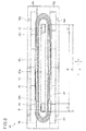
- FIG. 5 is a plan view showing the disposition of the coil 37, end center core 42, and side core 43 with respect to the bobbin 38 as seen from above (i.e., from the arched core holder 45 side) in FIG. 3 .
- core installation sections 45b in which arched cores 41 are attached at predetermined positions, are formed in the arched core holder 45.
- a plurality of core installation sections 45b is formed at roughly even intervals in the lengthwise direction (i.e., the paper widthwise direction X orthogonal to the paper conveyance direction Y) of the arched core holder 45.
- Holder apertures 45c are formed between adjacent core installation sections 45b.
- a plurality of bolt holes 45d into which the bolts 51 (see FIG. 3 ) for attaching the arched core holder 45 to the bobbin 38 (see FIG. 3 ) are screwed is formed around the core installation sections 45b.
- the arched cores 41 are formed from a manganese-zinc alloy-based or other type of high magnetic permeability ferrite so as to have an arched shape with a rectangular cross section.
- the Curie temperature of the arched cores 41 is at least the temperature of the arched cores 41 when the nip N has reached a fusable temperature.
- the magnetic permeability of the arched cores 41 will decrease sharply, and they will cease to function as magnetic bodies.
- the plurality of arched cores 41 is encompassed within the length of the coil 37 (see FIG. 5 ) in the lengthwise direction (paper widthwise direction X), and is disposed at uniform intervals along the length of the coil 37 (see FIG. 5 ) in the lengthwise direction (paper widthwise direction X).
- the rising wall 38c rising from the attachment surface 38b, the flanges 38d, and a plurality of bolt holes 38e into which the bolts 51 (see FIG. 3 ) are screwed is formed in the bobbin 38.
- the plurality of side cores 43 is attached to the flanges 38d.
- the side cores 43 are formed in rectangular shapes from a manganese-zinc alloy-based or other type of high magnetic permeability ferrite, and the Curie temperature thereof is at least the temperature of the side cores 43 when the nip N has reached a fusable temperature. When the temperature of the side cores 43 is higher than the Curie temperature thereof, the magnetic permeability of the side cores 43 will decrease sharply, and they will cease to function as magnetic bodies.
- a plurality of side cores 43 is disposed on one of the flanges 38d of the bobbin 38 in the paper widthwise direction X (hereafter simply "widthwise direction X") with the side surfaces thereof in contact with one another.
- a plurality of side cores 43 is also disposed on the other flange 38d in the widthwise direction X with the side surfaces thereof in contact with one another.
- the rising wall 38c of the bobbin 38 has wall sections extending in the widthwise direction X and opposing one another, and arcuate wall sections extending into the opposing wall sections and forming an outer edge at both ends in the widthwise direction X.
- the outer edge of the rising wall 38c has roughly the same shape as a hollow section 37a formed within the looped coil 37, and allows the hollow section 37a of the coil 37 to be fitted thereto and the coil 37 to be attached.
- the inner edge of the rising wall 38c forms a rectangular space within which a pair of end center cores 42 is disposed. This rectangular space has a length in the widthwise direction X corresponding to the paper passage area A of the maximum size of fusable paper 9.
- the rising wall 38c has a predetermined thickness so as to keep heat from the excited coil 37 from being radiated or conveyed to the end center cores 42.
- a pair of end center cores 42, 42 is attached within the rectangular space of the rising wall 38c.
- the end center cores 42, 42 are disposed so as to oppose an end area C of the paper passage area A of the maximum size of paper 9 when the maximum size of paper 9 passes through the nip N.
- the end area C is the area formed, for example, to the outside in the widthwise direction X of a central area B formed as a paper passage area when paper 9 of a size smaller than the maximum size of paper 9 passes through the nip N.
- the end center cores 42 are formed from a manganese-zinc alloy-based or other type of high magnetic permeability ferrite in a shape as described below.
- the Curie temperature thereof is at least the temperature of the end center cores 42 when the nip N has reached a fusable temperature.
- the temperature of the end center cores 42 is higher than the Curie temperature thereof, the magnetic permeability of the end center cores 42 will decrease sharply, and they will cease to function as magnetic bodies.
- FIGS. 6 and 7 show the configuration of the end center cores 42 in detail.
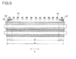
- FIG. 6 is a plan view of the configuration of end center cores 42.
- FIG. 7 is a perspective illustration of the configuration of the right end center core 42 illustrated in FIG. 6 .
- the right front side of FIG. 7 is the end (outer side) in the widthwise direction X
- the inner left side of FIG. 7 is the center (inner side) in the widthwise direction X.
- the coil 37, bobbin 38, and arched core holder 45 have been omitted for convenience.
- the end center cores 42 are formed as quadrangular prisms (see FIG. 7 ) having a pair of trapezoidal faces. As shown in FIG. 7 , one end center core 42 has a first surface 42a, a second surface 42b, third surfaces 42c, 42c, an inner surface 42d, and an outer surface 42e.
- the first surface 42a is a surface facing the heat-generating belt 26 (see FIG. 6 ).
- the second surface 42b is a surface facing the arched core 41 (see FIG. 6 ), and includes the widthwise direction X and the paper conveyance direction Y.
- the third surfaces 42c are surfaces facing each other in the paper conveyance direction Y.
- the inner surface 42d is a surface facing the center with respect to the widthwise direction X.
- the outer surface 42e is a surface on the outer end side in the widthwise direction X facing the inner surface 42d, and is parallel with the inner surface 42d.
- the inner surface 42d is formed in a rectangular shape, and has an inner core surface area S1.
- the outer surface 42e is formed in a rectangular shape and has an outer core surface area S2.
- the inner surface 42d and outer surface 42e may be rectangles with the long sides thereof extending in either the vertical or the horizontal direction, or may be squares.
- the first surface 42a is formed in a rectangular shape.
- the second surface 42b is formed in a rectangular shape.
- the third surfaces 42c, 42c are formed in trapezoidal shapes, and face each other in parallel.
- the first surface 42a is disposed inclining in a direction approaching the heat-generating belt 26 (see FIG. 6 ) from the center side with respect to the widthwise direction X (i.e., the rear left side in FIG. 7 ) to the end side (i.e., the front right side in FIG. 7 ).
- the second surface 42b is disposed in parallel to the heat-generating belt 26.
- the outer core surface area S2 of the end center core 42 is greater than the inner core surface area S1.
- the core cross-sectional area of the end center core 42 gradually increases towards the end in the widthwise direction X.
- the end center core 42 gathers more of the magnetic flux generated by the coil 37 (see FIG. 3 ), and the magnetic flux is guided to the heat-generating belt 26.
- the core cross-sectional area of the end center cores 42 gradually increases from the center side with respect to the widthwise direction X toward the outer end side, thereby generating an increasingly large amount of heat from the center side with respect to the widthwise direction X to the outer end side by the heat-generating belt 26 during inductive heating.
- the arched core 41, side core 43, and end center cores 42 are in a state of high magnetic permeability when the coil 37 is electrified and the nip N is maintained at a temperature no greater than the fusable temperature.
- the magnetic flux generated by the coil 37 follows a magnetic path passing through the inductive heat-generating layer 26a of the heat-generating belt 26, the side core 43, and the arched core 41 in the central area B (see FIG. 6 ). This causes an eddy current to flow through the inductive heat-generating layer 26a of the heat-generating belt 26, and the inductive heat-generating layer 26a of the heat-generating belt 26 to generate heat.
- the magnetic flux generated by the coil 37 follows a magnetic path passing through the end center core 42, the inductive heat-generating layer 26a of the heat-generating belt 26, the side core 43, and the arched core 41 in FIG. 3 .
- This causes an eddy current to flow through the inductive heat-generating layer 26a of the heat-generating belt 26, and the inductive heat-generating layer 26a of the heat-generating belt 26 to generate heat.
- a fuser device provided with, for example, a coil looped along the lengthwise direction of the heating member and a magnetic core extending along the paper widthwise direction (lengthwise direction) in the gap formed by the rings of the looped coil are provided, the coil being configured so that, for example, an inner part of a U-shaped wrapping part at the end of the lengthwise direction of the coil roughly corresponds to the end of the maximum paper width subjected to fusing, the magnetic core will normally extend to the two ends of the paper width of the maximum paper size. Less magnetic flux will be generated by the coil near the U-shaped wrapping part of the coil than at the other parts of the coil.
- the heat from the heating member is liable to be released to the outside of the fuser device due to heat radiation or conduction at the two ends in the lengthwise direction of the heating member. For this reason, it is difficult to attain a uniform temperature along the lengthwise direction of the heating member, and the temperature of the two ends of the heating member tends to be lower than the temperature of the center of the heating member.
- the temperature at the ends of the paper may be less than the desired fusing temperature even if the center of the paper has reached the appropriate fusing temperature; in such cases, fusion defects such as low temperature offset may occur.
- the fuser device 5 allows for satisfactory fusion even at the ends of a recording medium using a simple configuration.
- end center cores 42 are disposed at both ends in the widthwise direction X, causing a large amount of the magnetic flux generated by the coil 37 to be gathered by the end center cores 42 and increasing the amount of heat generated by the heat-generating belt 26 at the ends. Additionally, because the core surface area of the end center cores 42 grows larger towards the end in the widthwise direction X, the end center cores 42 gather increasingly more magnetic flux towards the ends thereof in the widthwise direction X, allowing for a uniform distribution of the magnetic flux density in the widthwise direction of the heat-generating belt 26.
- the magnetic flux generated by the coil passes through a magnetic path formed through the second core section, the inductive heat-generating layer of the heating member, and the first core section in the area at the end of the heating member in the lengthwise direction, resulting in the end area of the heating member being heated.
- the provision of the second core section allows the second core section to gather the surrounding magnetic flux.
- the fact that the core cross-sectional area of the second core section is formed so as to grow progressively larger from the center of the recording medium with respect to the widthwise direction to the ends allows for the second core section to gather progressively greater amounts of magnetic flux toward the ends of the recording medium with respect to the widthwise direction, allowing for a uniform magnetic flux density distribution in the lengthwise direction of the heating member.
- FIG. 8 is a plan view of the configuration of end center cores 42 according to a second embodiment.
- the coil 37, bobbin 38, and arched core holder 45 have been omitted for convenience.
- the shape of the end center cores 42 is different from that of the first embodiment. The following description will focus on the end center cores 42, and a description of parts identical to the first embodiment will be omitted.
- Each of the end center cores 42 is a quadrangular prism having a pair of trapezoidal surfaces, and has a first surface 42a, a second surface 42b, third surfaces 42c, 42c, an inner surface 42d, and an outer surface 42e.
- the first surface 42a is a surface facing the heat-generating belt 26.
- the second surface 42b is a surface facing the arched core 41, and comprises the widthwise direction X and the paper conveyance direction Y.
- the third surfaces 42c are surfaces facing each other in the paper conveyance direction Y.
- the inner surface 42d is a surface facing the center with respect to the widthwise direction X.
- the outer surface 42e is a surface on the outer end side in the widthwise direction X facing the inner surface 42d, and is parallel with the inner surface 42d.
- the inner surface 42d is formed in a rectangular shape, and has an inner core surface area S1.
- the outer surface 42e is formed in a rectangular shape and has an outer core surface area S2.
- the inner surface 42d and outer surface 42e may be rectangles with the long sides thereof extending in either the vertical or the horizontal direction, or may be squares.
- the first surface 42a is formed in a rectangular shape.
- the second surface 42b is formed in a rectangular shape.
- the third surfaces 42c, 42c are formed in trapezoidal shapes, and face each other in parallel.
- the first surface 42a is disposed in parallel to the heat-generating belt 26.
- the second surface 42b is disposed inclining away from the heat-generating belt 26 from the center side with respect to the widthwise direction X toward the end side.
- the outer core surface area S2 of the end center core 42 is greater than the inner core surface area S1.
- the core cross-sectional area of the end center core 42 gradually increases from the center side with respect to the widthwise direction X towards the end.
- the end center core 42 gathers more of the magnetic flux generated by the coil 37 (see FIG. 3 ), and the magnetic flux is guided to the heat-generating belt 26.
- the core cross-sectional area of the end center cores 42 gradually increases toward the outer end side with respect to the widthwise direction X, thereby generating an increasingly large amount of heat from the center side with respect to the widthwise direction X to the outer end side by the heat-generating belt 26 during inductive heating.
- end center cores 42 are disposed at both ends in the widthwise direction X, causing a large amount of the magnetic flux generated by the coil 37 to be gathered by the end center cores 42 and increasing the amount of heat generated by the heat-generating belt 26 at the ends. Additionally, because the core surface area of the end center cores 42 grows larger from the center towards the end in the widthwise direction X, the end center cores 42 gather increasingly more magnetic flux from the center towards the ends thereof in the widthwise direction X, allowing for a uniform distribution of the magnetic flux density in the widthwise direction of the heat-generating belt 26.
- FIG. 9 is a plan view of the configuration of an end center core 42 according to a third embodiment as seen from above in FIG. 3 .
- the shape of the end center cores 42 is different from that of the cores of the first and second embodiments.
- the bobbin 38 and arched core holder 45 have been omitted for convenience.
- Each of the end center cores 42 is a quadrangular prism having a pair of trapezoidal surfaces, and has a first surface 42a (the bottom surface facing the second surface 42b; not visible in FIG. 9 ), a second surface 42b, third surfaces 42c, 42c, an inner surface 42d, and an outer surface 42e.
- the first surface 42a is a surface facing the heat-generating belt 26 (see FIG. 3 ).
- the second surface 42b is a surface facing the arched core 41, and comprises the widthwise direction X and the paper conveyance direction Y.
- the third surfaces 42c are surfaces facing each other in the paper conveyance direction Y.
- the inner surface 42d is a surface facing the center with respect to the widthwise direction X.
- the outer surface 42e is a surface on the outer end side in the widthwise direction X facing the inner surface 42d, and is parallel with the inner surface 42d.
- the inner surface 42d is formed in a rectangular shape, and has an inner core surface area S1.
- the outer surface 42e is formed in a rectangular shape and has an outer core surface area S2.
- the inner surface 42d and outer surface 42e may be rectangles with the long sides thereof extending in either the vertical or the horizontal direction, or may be squares.
- the first surface 42a and second surface 42b are trapezoidal surfaces disposed in parallel to the heat-generating belt 26.
- the third surfaces 42c, 42c are rectangular surfaces disposed facing one another so as to be positioned progressively farther apart from each other from the center side with respect to the widthwise direction X toward the end side.
- the outer core surface area S2 of the end center core 42 is greater than the inner core surface area S1.
- the core cross-sectional area of the end center core 42 gradually increases from the center side with respect to the widthwise direction X towards the end.
- the end center core 42 gathers more of the magnetic flux generated by the coil 37 (see FIG. 3 ), and the magnetic flux is guided to the heat-generating belt 26.
- the core cross-sectional area of the end center cores 42 grows progressively larger in the widthwise direction X, causing the amount of heat generated to increase toward the ends of the heat-generating belt 26.
- end center cores 42 are disposed at both ends in the widthwise direction X, causing a large amount of the magnetic flux generated by the coil 37 to be gathered by the end center cores 42 and increasing the amount of heat generated by the heat-generating belt 26 at the ends. Additionally, because the core surface area of the end center cores 42 grows larger from the center towards the end in the widthwise direction X, the end center cores 42 gather increasingly more magnetic flux from the center towards the ends thereof in the widthwise direction X, allowing for a uniform distribution of the magnetic flux density in the widthwise direction of the heat-generating belt 26.
- the first surface 42a of the end center core 42 is disposed inclined with respect to the heat-generating belt 26 in the first embodiment described above, and the second surface 42b is disposed inclined with respect to the heat-generating belt 26 in the second embodiment, but the present disclosure is not limited to this.
- both the first surface 42a and the second surface 42b may be inclined with respect to the heat-generating belt 26.
- the pair of third surfaces 42c, 42c, along with the first surface 42a and the second surface 42b, may also be disposed facing each other so as to be positioned progressively farther apart from each other from the center side with respect to the widthwise direction X toward the end side.
- the end center cores 42 are quadrangular prisms, but not by way of limitation in the present disclosure.
- a configuration in which at least one surface extending in the widthwise direction X of another type of polygonal prism is inclined with respect to the heat-generating belt 26 is acceptable, or a cylindrical shape is also acceptable.
- the arched core 41 and the side core 43 were provided separately, but not by way of limitation in the present disclosure; a configuration in which the arched core 41 is further extended toward the side core 43 side and the arched core 41 takes over the functions of the side core 43 is also acceptable.
- the arched core 41 is attached to the bobbin 38 with the arched core holder 45 interposed therebetween, but not by way of limitation in the present disclosure; the arched core 41 may also be directly attached to the bobbin 38.
- examples of the disclosure being applied at a fuser device 5 in which the heat-generating belt 26 is held in a tensed state around the fusing roller 18 have been given, but not by way of limitation in the present disclosure; the disclosure may also be applied to a fuser device in which an endless heat-generating belt is held in a tensed state between a heat roller disposed so as to face a inductive heating unit and a fusing roller pressed against a pressure-applying roller.
- the present disclosure may also be applied to a fuser device provided with an inductive heating unit for heating an endless heat-generating belt; a pressure-applying roller pressed against the outer circumferential surface of the heat-generating belt; and a pressing member, disposed on the inner circumferential surface of the heat-generating belt, for pressing the paper and the heat-generating belt together against the pressure-applying roller.
- the present disclosure may also be applied to various types of fuser devices provided with inductive heating units, such as a fuser device provided with a pressure-applying roller and a heating roller pressed against the pressure-applying roller, the heating roller containing an inductive heat-generating layer within itself and is disposed facing an inductive heating unit.
- the heat-generating belts 26 used in the fuser devices 5 subjected to testing had inner diameters of 35 mm and lengths in the lengthwise direction of 340 mm.
- the inductive heat-generating layers 26a were formed from electroformed nickel to a thickness of 40 ⁇ m.
- the elastic layers 26b were formed from silicone rubber to a thickness of 200 ⁇ m.
- the mold release layers 26c were formed from 30 ⁇ m-thick fluororesin tubing.
- rollers having elastic layers 18b of 9 mm-thick foamed silicone rubber over metal cores 18a of an aluminum alloy were used for the fusing rollers 18.
- the rollers used for the pressure-applying rollers 19 had outer diameters of 30 mm, and had elastic layers 19b of 5 mm-thick foamed silicone rubber over metal cores 19a of iron, as well as 50 ⁇ m-thick mold release layers 19c formed from fluororesin tubing over elastic layers 19b.
- the coils 37 were looped a plurality of times in the lengthwise direction to a length of 370 mm. Arched cores 41, end center cores 42, and side cores 43 formed from ferrite were used.
- the fusing load was set to 300 N (150 N per side x 2), the heat-generating belt 26 was driven to rotate at an outer circumference speed of 270 mm/sec, and the center of the heat-generating belt 26 in the lengthwise direction was made to generate heat at 175°C.
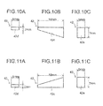
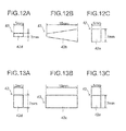
- FIGS. 10A-13C show the shapes of the end center cores 42.
- FIGS. 10A-10C show the shape of the end center cores 42 in working example 1.
- FIGS. 11A-11C show the shape of the end center cores 42 in working example 2.
- FIGS. 12A-12C show the shape of the end center cores 42 in working example 3.
- FIGS. 13A-13C show the shape of the end center cores 42 in comparative example 2. Comparative example 1 is not illustrated as it was not provided with end center cores 42.
- FIGS. 10A-13C show the shapes of the end center cores 42.
- FIGS. 10A-10C show the shape of the end center cores 42 in working example 1.
- FIGS. 11A-11C show the shape of the end center cores 42 in working example 2.
- FIGS. 12A-12C show the shape of the end center cores 42 in working example 3.
- FIGS. 13A-13C show the shape of the end center cores 42 in comparative example 2. Comparative example 1 is not illustrated as it was not
- FIGS. 10A, 11A , 12A, and 13A show the inner surface 42d of the end center core 42.
- FIGS. 10B, 11B , 12B, and 13B show a plan view of the end center core 42 (12B being a plan view as seen from above).
- FIGS. 10C, 11C , 12C, and 13C show the outer surface 42e of the end center core 42. The lengths of each side of the end center core 42 were as shown in the drawings.
- Working example 1 had a shape corresponding to the first embodiment, working example 2 corresponding to the second embodiment, and working example 3 corresponding to the third embodiment.
- the core surface area S1 of the inner surface 42d for each of working examples 1-3 was 10 mm 2
- the core surface area of the outer surface 42e was 35 mm 2 .
- comparative example 1 as described above, is an example not provided with end center cores 42.
- Comparative example 2 used rectangular end center cores 42, the core surface area S1 of the inner surface 42d thereof being 35 mm 2 , and the core surface area of the outer surface 42e being 35 mm 2 .
- FIG. 14 shows the temperature distribution of the heat-generating belt 26 when fusing is performed upon the maximum size of paper.
- the horizontal axis of the graph in FIG. 14 shows the position of the heat-generating belt 26 in the lengthwise direction (in millimeters) in the paper passage area A of the maximum size of paper, and the vertical axis shows the temperature (°C) of the heat-generating belt 26.
- the position in the lengthwise direction of the horizontal axis is the length based on the center position of the heat-generating belt 26.
- Line M in FIG. 14 indicates the minimum temperature at which fusing defects due to high-temperature offset can occur
- line N indicates the maximum temperature at which fusing defects due to low-temperature offset can occur.
- Table 1 The evaluation results for working examples 1-3 and comparative examples 1 and 2 are shown in Table 1.
- ⁇ indicates no fusing problems, and ⁇ indicates the occurrence of a fusing defect due to low-temperature offset or high-temperature offset.
- Working Example 1 Working Example 2
- Working Example 3 Comparative Example 1 Comparative Example 2 Center of paper ⁇ ⁇ ⁇ ⁇ ⁇ Ends of paper ⁇ ⁇ ⁇ ⁇ ⁇
- the temperature at the ends of the paper passage area A in comparative example 1 was 155°C, and a fusing defect occurred due to low-temperature offset.
- the temperature at the ends of the paper passage area A in comparative example 2 was 210°C, and a fusing defect occurred due to high-temperature offset.
- the temperature at the ends of the paper passage area A was 185°C, and there were no fusing problems. Nearly the same results were obtained for working examples 2 and 3, and there were no fusing problems.
- the present disclosure can be used for a fuser device used in a photocopier, printer, fax machine, a multifunction machine combining these functions, or the like, and for an image forming apparatus provided with the same.
- the present disclosure can be used for a fuser device utilizing electromagnetic induction heating and an image forming apparatus provided with the same.
Landscapes
- Physics & Mathematics (AREA)
- General Physics & Mathematics (AREA)
- Fixing For Electrophotography (AREA)
- General Induction Heating (AREA)
- Printers Or Recording Devices Using Electromagnetic And Radiation Means (AREA)
Abstract
Description
- The present disclosure relates to a fuser device and an image forming apparatus provided with the same, and in particular to a fuser device utilizing electromagnetic induction heating and an image forming apparatus provided with the same.
- A fuser device utilizing electromagnetic induction heating is provided with, for example, a heating member, a pressure-applying member pressed against the heating member, a magnetic core having a predetermined Curie temperature, and a coil for generating a magnetic flux using the magnetic core to inductively heat the heating member. The fuser device generates an eddy current in an inductive heat-generating layer provided within the heating member via the magnetic core using the magnetic flux generated by the coil, generates heat in the heating member using joule heat generated by the eddy current, and heats the heating member to a predetermined fusing temperature.
- The coil is, for example, looped around the heating member along the lengthwise direction thereof, and the magnetic core extends along the paper widthwise direction (that is, lengthwise direction of the magnetic core) in the gap formed by the rings of the looped coil. The coil is configured so that, for example, an inner part of a U-shaped wrapping part at the end of the lengthwise direction of the coil roughly corresponds to the end of the maximum paper width subjected to fusing. Such a configuration may suitably dispose the coil with respect to the heating member provided with the inductive heat-generating layer, and enables uniform heating along the paper widthwise direction.
- A fuser device according to an aspect of the present disclosure is provided with a heating member; a pressure-applying member pressed against the heating member; a nip, formed by the heating member and the pressure-applying member, and configured to clamp a recording medium bearing an unfused toner image and melting and fusing the unfused toner image on the recording medium; a coil for generating a magnetic flux for inductively heating the heating member looped around the heating member in the lengthwise direction thereof; and a magnetic core, disposed near the coil in the widthwise direction of the recording medium orthogonally to the conveyance direction of the recording medium, and configured to guide the magnetic flux to an inductive heat-generating layer of the heating member. The magnetic core is provided with a first core section surrounding the coil and disposed along the widthwise direction, and a second core section disposed at both ends in the widthwise direction within the hollow area which the loop of the coil forms, the second core section being formed so that the cross-sectional area thereof in the conveyance direction of the recording medium grows progressively larger from the center of the widthwise direction towards the end thereof.
- Objects of the present disclosure and specific advantages of the present disclosure will become apparent from the description of embodiments given below.
-
-
FIG. 1 is a schematic view of an image forming apparatus provided with a fuser device according to a first embodiment of the present disclosure. -
FIG. 2 is a side cross-sectional view of a fuser device provided with an inductive heating unit according to the first embodiment of the present disclosure. -
FIG. 3 is a side cross-sectional view of an inductive heating unit according to the first embodiment of the present disclosure. -
FIG. 4 is a plan view of the disposition of an arched core of an inductive heating unit according to the first embodiment of the present disclosure. -
FIG. 5 is a plan view showing the disposition of an end center core of an inductive heating unit according to the first embodiment of the present disclosure. -
FIG. 6 is a plan view of the configuration of the end center core according to the first embodiment of the present disclosure. -
FIG. 7 is a perspective view of the configuration of the end center core according to the first embodiment of the present disclosure. -
FIG. 8 is a plan view of the configuration of an end center core according to a second embodiment of the present disclosure. -
FIG. 9 is a plan view of the configuration of an end center core according to a third embodiment of the present disclosure. -
FIG. 10A is an illustration of the shape of the inner surface of an end center core according to a first working example of the present disclosure. -
FIG. 10B is a plan view of the shape of the end center core according to the first working example of the present disclosure. -
FIG. 10C is an illustration of the shape of the outer surface of the end center core according to the first working example of the present disclosure. -
FIG. 11A is an illustration of the shape of the inner surface of an end center core according to a second working example of the present disclosure. -
FIG. 11B is a plan view of the shape of the end center core according to the second working example of the present disclosure. -
FIG. 11C is an illustration of the shape of the outer surface of the end center core according to the second working example of the present disclosure. -
FIG. 12A is an illustration of the shape of the inner surface of an end center core according to a third working example of the present disclosure. -
FIG. 12B is a plan view of the shape of the end center core as seen from above according to the third working example of the present disclosure. -
FIG. 12C is an illustration of the shape of the outer surface of the end center core according to the third working example of the present disclosure. -
FIG. 13A is an illustration of the shape of the inner surface of an end center core according to a second comparative example of the present disclosure. -
FIG. 13B is a plan view of the shape of the end center core according to the second comparative example of the present disclosure. -
FIG. 13C is an illustration of the shape of the outer surface of the end center core according to the second comparative example of the present disclosure. -
FIG. 14 is an illustration of the temperature distribution of the heating members according to the working and comparative examples of the present disclosure. - Embodiments of the present disclosure are described below while referring to the drawings, but the present disclosure is not restricted to the following embodiments. The application of the disclosure and the terms and the like indicated herein are not restricted to the following.
-
FIG. 1 is a schematic view of an image forming apparatus provided with a fuser device according to an embodiment of the present disclosure. An image forming apparatus 1 is provided with apaper feeding unit 2 disposed in the lower part thereof, apaper conveying unit 3 disposed to the side of thepaper feeding unit 2, animage forming unit 4 disposed above thepaper conveying unit 3, afuser device 5 disposed closer to an output side than theimage forming unit 4, and animage scanner unit 6 disposed above theimage forming unit 4 and thefuser device 5. - The
paper feeding unit 2 is provided with a plurality ofpaper feeding cassettes 7 for containing paper 9 (an example of a recording medium), and the rotation of apaper feeding roller 8 sends out one sheet of thepaper 9 at a time from apaper feeding cassette 7 selected from among the plurality ofpaper feeding cassettes 7 to thepaper conveying unit 3. - The
paper 9 sent out to thepaper conveying unit 3 is conveyed toward theimage forming unit 4 via apaper conveyance path 10 provided in thepaper conveying unit 3. Theimage forming unit 4 forms a toner image on thepaper 9 using an electrophotographic process. Theimage forming unit 4 is provided with aphotoreceptor 11 supported so as to be capable of rotating in the direction of the arrow illustrated inFIG. 1 , and anelectrostatic unit 12,exposure unit 13,developer unit 14,transfer unit 15,cleaning unit 16, and astatic eliminator unit 17 disposed around thephotoreceptor 11 in the direction of rotation of thephotoreceptor 11. - The
electrostatic unit 12 is provided with an electrostatic wire to which a high voltage is applied. A predetermined toner image is applied to the surface of thephotoreceptor 11 using corona discharge from the electrostatic wire, thereby uniformly imparting the surface of thephotoreceptor 11 with an electrostatic charge. Thephotoreceptor 11 is then irradiated by theexposure unit 13 with light based on document image data, for example scanned by theimage scanner unit 6, selectively attenuating the surface electrical potential of thephotoreceptor 11, and forming a latent electrostatic image on the surface of thephotoreceptor 11. - The
developer unit 14 develops the latent electrostatic image on the surface of thephotoreceptor 11, forming a toner image on the surface of thephotoreceptor 11. The toner image is transferred by thetransfer unit 15 topaper 9 fed between thephotoreceptor 11 and thetransfer unit 15. Thepaper 9 to which the toner image has been transferred is conveyed toward thefuser device 5 disposed at the downstream side in the paper conveyance direction of theimage forming unit 4. Heat and pressure are applied to thepaper 9 in thefuser device 5, melting and fusing the toner image on thepaper 9. Thepaper 9 to which the toner image has been fused is outputted onto anoutput tray 21 by anoutput roller pair 20. - After the toner image has been transferred to the
paper 9 by thetransfer unit 15, residual toner on the surface of thephotoreceptor 11 is removed by thecleaning unit 16, and the residual charge on the surface of thephotoreceptor 11 is removed by thestatic eliminator unit 17. Thephotoreceptor 11 is then again electrostatically charged by theelectrostatic unit 12, and an image is formed in the same manner. - The
fuser device 5 is configured as shown inFIG. 2. FIG. 2 is a side cross-sectional schematic view of thefuser device 5 according to the present embodiment. - The
fuser device 5 performs fusion using electromagnetic induction heating. Thefuser device 5 is provided with a heat-generatingbelt 26 acting as a heating member, a pressure-applyingroller 19 acting as a pressure-applying member, a fusingroller 18 integrally attached to the heat-generatingbelt 26, and aninductive heating unit 30 for supplying a magnetic flux to the heat-generatingbelt 26. The pressure-applyingroller 19 and fusingroller 18 are supported so as to be capable of rotating in the lengthwise direction of a housing (not shown) of thefuser device 5. Theinductive heating unit 30 is mounted to and supported by the housing. - The heat-generating
belt 26 is an endless heat-resistant belt. The heat-generatingbelt 26 has, for example, a configuration in which an inductive heat-generating layer 26a formed, for example, by using electroformed nickel of a thickness of at least 30 µm and no more than 50 µm, anelastic layer 26b of, for example, silicone rubber of a thickness of at least 200 µm and no more than 500 µm, and amold release layer 26c formed using, for example, a fluororesin of a thickness of about 30 µm are layered in that order from the inner circumference side of the belt. The provision of themold release layer 26c allows for improved releasability when the unfused toner image is being melted and fused at the nip N, which is formed at the part where the pressure-applyingroller 19 and the heat-generatingbelt 26 are pressed together. - The fusing
roller 18 holds the inner circumference side of the heat-generatingbelt 26 in a tensed state so as to capable of rotating integrally with the heat-generatingbelt 26. The fusingroller 18 has ametal core 18a of, for example, an aluminum alloy, and anelastic layer 18b formed over themetal core 18a from, for example, foamed silicone rubber to a thickness of at least 5 mm to no more than 10 mm. Theelastic layer 18b holds the heat-generatingbelt 26 in a tensed state. - The outer diameter of the pressure-applying
roller 19 is, for example, 30 mm. The pressure-applyingroller 19 has a cylindricaliron metal core 19a, and anelastic layer 19b formed over themetal core 19a from, for example, foamed silicone rubber to a thickness of at least 2 mm and no more than 5 mm. The pressure-applyingroller 19 has an approximately 50 µm-thickmold release layer 19c formed over theelastic layer 19b from a fluororesin or the like. The pressure-applyingroller 19 is rotatably driven by motive power from a motor or the like not shown in the drawings, and the heat-generatingbelt 26 is driven to rotate by the rotation of the pressure-applyingroller 19. At the nip N, heat and pressure are applied to the unfused toner image on the conveyedpaper 9, fusing the toner image to thepaper 9. - The
inductive heating unit 30 is provided with acoil 37, abobbin 38, and amagnetic core 39, and causes the heat-generatingbelt 26 to generate heat via electromagnetic induction. Theinductive heating unit 30 extends in the lengthwise direction (i.e., the direction proceeding inward from the surface ofFIG. 2 ), and is disposed opposing the heat-generatingbelt 26 so as to cover roughly half of the outer circumference of the heat-generatingbelt 26. - The
coil 37 is looped a plurality of times along the widthwise direction of the heat-generating belt 26 (the direction proceeding inward from the surface ofFIG. 2 ) and is attached to thebobbin 38. Thecoil 37 is connected to a power source not shown in the drawings, and generates an AC magnetic flux using high-frequency current supplied from the power source. The magnetic flux from thecoil 37 passes through themagnetic core 39, is guided in a direction parallel to the surface ofFIG. 2 , and passes through the inductive heat-generating layer 26a of the heat-generatingbelt 26. Variations in the AC strength of the magnetic flux passing through the inductive heat-generating layer 26a create an eddy current in the inductive heat-generating layer 26a. When the eddy current flows through the inductive heat-generating layer 26a, joule heat is generated by the electrical resistance of the inductive heat-generating layer 26a, and the heat-generatingbelt 26 generates heat (spontaneously). - When the heat-generating
belt 26 is heated to a predetermined temperature, thepaper 9 clamped in the nip N is heated and pressure is applied by the pressure-applyingroller 19, melting and fusing the powdered toner on thepaper 9 to thepaper 9. The heat-generatingbelt 26 is formed from a thin material having good heat conductivity and has a small heat capacity, allowing thefuser device 5 to be warmed up in a short period of time, and quickly initiating image formation. -
FIG. 3 shows the configuration of theinductive heating unit 30 in detail.FIG. 3 is a side cross-sectional view of theinductive heating unit 30. - The
inductive heating unit 30 is provided, as described above, with thecoil 37, thebobbin 38 acting as a support member, and themagnetic core 39. Themagnetic core 39 has anarched core 41 constituting a first core, anend center core 42 constituting a second core, and aside core 43. Theinductive heating unit 30 is further provided with anarched core holder 45, and acover member 47 for covering themagnetic core 39 and thecoil 37. Thearched core 41 is attached to thearched core holder 45. - The
bobbin 38 is disposed concentrically with the rotational center of the fusingroller 18 at a predetermined spacing from the surface of the heat-generatingbelt 26. Thebobbin 38 has an arcuate portion 38i covering roughly half of the circumferential surface of the heat-generatingbelt 26, andflanges 38d extending from both ends of the arcuate portion 38i. The arcuate portion 38i and theflanges 38d constitute the primary frame of thebobbin 38. The arcuate portion 38i and theflanges 38d have a predetermined thickness so as to allow the strength of the frame to be maintained. The arcuate portion 38i andflanges 38d are formed from a heat-resistant plastic such as LCP plastic (liquid crystal polymer), PET plastic (polyethylene terephthalate plastic), or PPS plastic (polyphenylene sulfide plastic). Forming the arcuate portion 38i andflanges 38d from these plastics allows, for example, the resistance thereof to the heat given off by the heat-generatingbelt 26 to be improved. - The arcuate portion 38i of the
bobbin 38 has a facingsurface 38a facing the surface of the heat-generatingbelt 26 across a predetermined spacing, and anarcuate attachment surface 38b positioned on the opposite side from the facingsurface 38a. A pair ofend center cores 42 is attached by adhesive substantially in the center of theattachment surface 38b, i.e., over a straight line connecting the central rotational axes of the fusingroller 18 and the pressure-applying roller 19 (seeFIG. 2 ). A risingwall 38c rising up from theattachment surface 38b is formed on the circumference of theend center core 42 so as to extend in the lengthwise direction (i.e., the direction proceeding inward from the surface ofFIG. 3 ). Thecoil 37 is attached to theattachment surface 38b. The surface of the heat-generatingbelt 26 and the facingsurface 38a of thebobbin 38 are disposed with a predetermined spacing therebetween. Such a configuration allows contact of the heat-generatingbelt 26 with thebobbin 38 during rotation of the heat-generatingbelt 26 to be suppressed. - The
coil 37 is formed from a plurality of, for example, enamel wires coated with a melt-fused layer that have been twisted together, an example being AIW wire. Thecoil 37 is heated in a state of being looped around the lengthwise direction (i.e., the direction proceeding inward from the surface ofFIG. 3 ) in an arcuate manner along theattachment surface 38b as seen in cross section to melt the melt-fused layer, then cooled to form a predetermined shape (i.e., a looped shape). Having been solidified in the predetermined shape, thecoil 37 is disposed around the risingwall 38c of thebobbin 38 and attached to theattachment surface 38b by a silicone adhesive or the like. - A plurality of
side cores 43 arrayed in the lengthwise direction are attached to the arcuate portion 38i side of theflanges arched core holder 45 is attached to the outside edges of theflanges 38d. - The
arched core holder 45 hasholder flanges 45a for attaching to theflanges 38d of thebobbin 38, and a plurality ofcore installation sections 45b formed in the lengthwise direction and arching away from theholder flanges 45a. Anarched core 41 having roughly the same arched shape as thecore installation sections 45b is attached to thecore installation sections 45b using an adhesive. - Thus, when the
arched core 41 and theend center core 42 andside core 43 are attached to predetermined positions on thearched core holder 45 and thebobbin 38, respectively, the outside of thecoil 37 is surrounded by thearched core 41 and theside core 43. Theend center core 42 is disposed nearer to the surface of the heat-generatingbelt 26 than thearched core 41. Furthermore, thecoil 37 is surrounded by the surface of the heat-generatingbelt 26, theside core 43, thearched core 41, and theend center core 42. The magnetic flux generated by thecoil 37 due to the high-frequency current being supplied thereto is guided to theside core 43,arched core 41, anend center core 42, and flows along the heat-generatingbelt 26. At this point, an eddy current is generated in the inductive heat-generating layer 26a of the heat-generatingbelt 26, causing joule heat to be generated in the inductive heat-generating layer 26a by the electrical resistance of the inductive heat-generating layer 26a, and the heat-generatingbelt 26 generates heat. - The
cover member 47 shields the magnetic flux generated by theinductive heating unit 30. Thecover member 47 is constituted by, for example, aluminum sheeting, and covers the area around thecoil 37 and themagnetic core 39 from the side opposite to thebobbin 38. Thecover member 47 is attached, for example, by layering theholder flanges 45a of thearched core holder 45 and the flanges of thecover member 47 in order over theflanges 38d of thebobbin 38, then fastening abolt 51 in place with anut 52. -
FIG. 4 andFIG. 5 show the disposition of thecoil 37 and themagnetic core 39 in detail.FIG. 4 is a plan view of thearched cores 41 with respect to thearched core holder 45 as seen from below (i.e., from thebobbin 38 side) inFIG. 3 .FIG. 5 is a plan view showing the disposition of thecoil 37,end center core 42, andside core 43 with respect to thebobbin 38 as seen from above (i.e., from thearched core holder 45 side) inFIG. 3 . - As shown in
FIG. 4 ,core installation sections 45b, in which archedcores 41 are attached at predetermined positions, are formed in thearched core holder 45. A plurality ofcore installation sections 45b is formed at roughly even intervals in the lengthwise direction (i.e., the paper widthwise direction X orthogonal to the paper conveyance direction Y) of thearched core holder 45.Holder apertures 45c are formed between adjacentcore installation sections 45b. A plurality ofbolt holes 45d into which the bolts 51 (seeFIG. 3 ) for attaching thearched core holder 45 to the bobbin 38 (seeFIG. 3 ) are screwed is formed around thecore installation sections 45b. - The
arched cores 41 are formed from a manganese-zinc alloy-based or other type of high magnetic permeability ferrite so as to have an arched shape with a rectangular cross section. The Curie temperature of thearched cores 41 is at least the temperature of thearched cores 41 when the nip N has reached a fusable temperature. When the temperature of thearched cores 41 is higher than the Curie temperature thereof, the magnetic permeability of thearched cores 41 will decrease sharply, and they will cease to function as magnetic bodies. The plurality ofarched cores 41 is encompassed within the length of the coil 37 (seeFIG. 5 ) in the lengthwise direction (paper widthwise direction X), and is disposed at uniform intervals along the length of the coil 37 (seeFIG. 5 ) in the lengthwise direction (paper widthwise direction X). - As shown in
FIG. 5 , the risingwall 38c rising from theattachment surface 38b, theflanges 38d, and a plurality ofbolt holes 38e into which the bolts 51 (seeFIG. 3 ) are screwed is formed in thebobbin 38. The plurality ofside cores 43 is attached to theflanges 38d. - The
side cores 43 are formed in rectangular shapes from a manganese-zinc alloy-based or other type of high magnetic permeability ferrite, and the Curie temperature thereof is at least the temperature of theside cores 43 when the nip N has reached a fusable temperature. When the temperature of theside cores 43 is higher than the Curie temperature thereof, the magnetic permeability of theside cores 43 will decrease sharply, and they will cease to function as magnetic bodies. A plurality ofside cores 43 is disposed on one of theflanges 38d of thebobbin 38 in the paper widthwise direction X (hereafter simply "widthwise direction X") with the side surfaces thereof in contact with one another. A plurality ofside cores 43 is also disposed on theother flange 38d in the widthwise direction X with the side surfaces thereof in contact with one another. - The rising
wall 38c of thebobbin 38 has wall sections extending in the widthwise direction X and opposing one another, and arcuate wall sections extending into the opposing wall sections and forming an outer edge at both ends in the widthwise direction X. - The outer edge of the rising
wall 38c has roughly the same shape as ahollow section 37a formed within the loopedcoil 37, and allows thehollow section 37a of thecoil 37 to be fitted thereto and thecoil 37 to be attached. The inner edge of the risingwall 38c forms a rectangular space within which a pair ofend center cores 42 is disposed. This rectangular space has a length in the widthwise direction X corresponding to the paper passage area A of the maximum size offusable paper 9. The risingwall 38c has a predetermined thickness so as to keep heat from theexcited coil 37 from being radiated or conveyed to theend center cores 42. - A pair of
end center cores wall 38c. Theend center cores paper 9 when the maximum size ofpaper 9 passes through the nip N. The end area C is the area formed, for example, to the outside in the widthwise direction X of a central area B formed as a paper passage area whenpaper 9 of a size smaller than the maximum size ofpaper 9 passes through the nip N. - The
end center cores 42 are formed from a manganese-zinc alloy-based or other type of high magnetic permeability ferrite in a shape as described below. The Curie temperature thereof is at least the temperature of theend center cores 42 when the nip N has reached a fusable temperature. When the temperature of theend center cores 42 is higher than the Curie temperature thereof, the magnetic permeability of theend center cores 42 will decrease sharply, and they will cease to function as magnetic bodies. -
FIGS. 6 and7 show the configuration of theend center cores 42 in detail.FIG. 6 is a plan view of the configuration ofend center cores 42.FIG. 7 is a perspective illustration of the configuration of the rightend center core 42 illustrated inFIG. 6 . The right front side ofFIG. 7 is the end (outer side) in the widthwise direction X, and the inner left side ofFIG. 7 is the center (inner side) in the widthwise direction X. InFIG. 6 , thecoil 37,bobbin 38, andarched core holder 45 have been omitted for convenience. - As shown in
FIG. 6 , theend center cores 42 are formed as quadrangular prisms (seeFIG. 7 ) having a pair of trapezoidal faces. As shown inFIG. 7 , oneend center core 42 has afirst surface 42a, asecond surface 42b,third surfaces inner surface 42d, and anouter surface 42e. - The
first surface 42a is a surface facing the heat-generating belt 26 (seeFIG. 6 ). Thesecond surface 42b is a surface facing the arched core 41 (seeFIG. 6 ), and includes the widthwise direction X and the paper conveyance direction Y. Thethird surfaces 42c are surfaces facing each other in the paper conveyance direction Y. Theinner surface 42d is a surface facing the center with respect to the widthwise direction X. Theouter surface 42e is a surface on the outer end side in the widthwise direction X facing theinner surface 42d, and is parallel with theinner surface 42d. Theinner surface 42d is formed in a rectangular shape, and has an inner core surface area S1. Theouter surface 42e is formed in a rectangular shape and has an outer core surface area S2. Theinner surface 42d andouter surface 42e may be rectangles with the long sides thereof extending in either the vertical or the horizontal direction, or may be squares. - The
first surface 42a is formed in a rectangular shape. Thesecond surface 42b is formed in a rectangular shape. Thethird surfaces first surface 42a is disposed inclining in a direction approaching the heat-generating belt 26 (seeFIG. 6 ) from the center side with respect to the widthwise direction X (i.e., the rear left side inFIG. 7 ) to the end side (i.e., the front right side inFIG. 7 ). Thesecond surface 42b is disposed in parallel to the heat-generatingbelt 26. Thus, the outer core surface area S2 of theend center core 42 is greater than the inner core surface area S1. The core cross-sectional area of theend center core 42 gradually increases towards the end in the widthwise direction X. - As the core cross-sectional area of the
end center cores 42 increases, theend center core 42 gathers more of the magnetic flux generated by the coil 37 (seeFIG. 3 ), and the magnetic flux is guided to the heat-generatingbelt 26. Thus, the core cross-sectional area of theend center cores 42 gradually increases from the center side with respect to the widthwise direction X toward the outer end side, thereby generating an increasingly large amount of heat from the center side with respect to the widthwise direction X to the outer end side by the heat-generatingbelt 26 during inductive heating. - In the
fuser device 5 according to the present embodiment, when fusing a toner image to the maximum size ofpaper 9, thearched core 41,side core 43, andend center cores 42 are in a state of high magnetic permeability when thecoil 37 is electrified and the nip N is maintained at a temperature no greater than the fusable temperature. Thus, inFIG. 3 , the magnetic flux generated by thecoil 37 follows a magnetic path passing through the inductive heat-generating layer 26a of the heat-generatingbelt 26, theside core 43, and thearched core 41 in the central area B (seeFIG. 6 ). This causes an eddy current to flow through the inductive heat-generating layer 26a of the heat-generatingbelt 26, and the inductive heat-generating layer 26a of the heat-generatingbelt 26 to generate heat. - Meanwhile, in the end area C (see
FIG. 6 ), the magnetic flux generated by thecoil 37 follows a magnetic path passing through theend center core 42, the inductive heat-generating layer 26a of the heat-generatingbelt 26, theside core 43, and thearched core 41 inFIG. 3 . This causes an eddy current to flow through the inductive heat-generating layer 26a of the heat-generatingbelt 26, and the inductive heat-generating layer 26a of the heat-generatingbelt 26 to generate heat. - In a fuser device provided with, for example, a coil looped along the lengthwise direction of the heating member and a magnetic core extending along the paper widthwise direction (lengthwise direction) in the gap formed by the rings of the looped coil are provided, the coil being configured so that, for example, an inner part of a U-shaped wrapping part at the end of the lengthwise direction of the coil roughly corresponds to the end of the maximum paper width subjected to fusing, the magnetic core will normally extend to the two ends of the paper width of the maximum paper size. Less magnetic flux will be generated by the coil near the U-shaped wrapping part of the coil than at the other parts of the coil. The heat from the heating member is liable to be released to the outside of the fuser device due to heat radiation or conduction at the two ends in the lengthwise direction of the heating member. For this reason, it is difficult to attain a uniform temperature along the lengthwise direction of the heating member, and the temperature of the two ends of the heating member tends to be lower than the temperature of the center of the heating member. Thus, the temperature at the ends of the paper may be less than the desired fusing temperature even if the center of the paper has reached the appropriate fusing temperature; in such cases, fusion defects such as low temperature offset may occur.
- However, the
fuser device 5 according to the embodiment of the present disclosure, as described above, allows for satisfactory fusion even at the ends of a recording medium using a simple configuration. - Specifically, in the present embodiment,
end center cores 42 are disposed at both ends in the widthwise direction X, causing a large amount of the magnetic flux generated by thecoil 37 to be gathered by theend center cores 42 and increasing the amount of heat generated by the heat-generatingbelt 26 at the ends. Additionally, because the core surface area of theend center cores 42 grows larger towards the end in the widthwise direction X, theend center cores 42 gather increasingly more magnetic flux towards the ends thereof in the widthwise direction X, allowing for a uniform distribution of the magnetic flux density in the widthwise direction of the heat-generatingbelt 26. For this reason, temperature differences in the widthwise direction of the heat-generatingbelt 26 are reduced, and fusion defects can be suppressed even at the ends of thepaper 9 using the simple feature of varying the cross-sectional area of theend center cores 42 in the widthwise direction X. This enables a good quality image to be obtained. - Specifically, in the fuser device according to the present embodiment, the magnetic flux generated by the coil passes through a magnetic path formed through the second core section, the inductive heat-generating layer of the heating member, and the first core section in the area at the end of the heating member in the lengthwise direction, resulting in the end area of the heating member being heated. The provision of the second core section allows the second core section to gather the surrounding magnetic flux. Additionally, the fact that the core cross-sectional area of the second core section is formed so as to grow progressively larger from the center of the recording medium with respect to the widthwise direction to the ends allows for the second core section to gather progressively greater amounts of magnetic flux toward the ends of the recording medium with respect to the widthwise direction, allowing for a uniform magnetic flux density distribution in the lengthwise direction of the heating member. Thus, temperature differences in the lengthwise direction of the heating member are reduced, and fusion defects can be suppressed even at the ends of the recording medium using the simple feature of varying the core cross-sectional area of the second core section in the widthwise direction of the recording medium, allowing a good quality image to be obtained.
-
FIG. 8 is a plan view of the configuration ofend center cores 42 according to a second embodiment. InFIG. 8 , thecoil 37,bobbin 38, andarched core holder 45 have been omitted for convenience. In the second embodiment, the shape of theend center cores 42 is different from that of the first embodiment. The following description will focus on theend center cores 42, and a description of parts identical to the first embodiment will be omitted. - Each of the
end center cores 42 is a quadrangular prism having a pair of trapezoidal surfaces, and has afirst surface 42a, asecond surface 42b,third surfaces inner surface 42d, and anouter surface 42e. - The
first surface 42a is a surface facing the heat-generatingbelt 26. Thesecond surface 42b is a surface facing thearched core 41, and comprises the widthwise direction X and the paper conveyance direction Y. Thethird surfaces 42c are surfaces facing each other in the paper conveyance direction Y. Theinner surface 42d is a surface facing the center with respect to the widthwise direction X. Theouter surface 42e is a surface on the outer end side in the widthwise direction X facing theinner surface 42d, and is parallel with theinner surface 42d. Theinner surface 42d is formed in a rectangular shape, and has an inner core surface area S1. Theouter surface 42e is formed in a rectangular shape and has an outer core surface area S2. Theinner surface 42d andouter surface 42e may be rectangles with the long sides thereof extending in either the vertical or the horizontal direction, or may be squares. - The
first surface 42a is formed in a rectangular shape. Thesecond surface 42b is formed in a rectangular shape. Thethird surfaces first surface 42a is disposed in parallel to the heat-generatingbelt 26. Thesecond surface 42b is disposed inclining away from the heat-generatingbelt 26 from the center side with respect to the widthwise direction X toward the end side. Thus, the outer core surface area S2 of theend center core 42 is greater than the inner core surface area S1. In addition, the core cross-sectional area of theend center core 42 gradually increases from the center side with respect to the widthwise direction X towards the end. - As the core cross-sectional area of the
end center cores 42 increases, theend center core 42 gathers more of the magnetic flux generated by the coil 37 (seeFIG. 3 ), and the magnetic flux is guided to the heat-generatingbelt 26. Thus, the core cross-sectional area of theend center cores 42 gradually increases toward the outer end side with respect to the widthwise direction X, thereby generating an increasingly large amount of heat from the center side with respect to the widthwise direction X to the outer end side by the heat-generatingbelt 26 during inductive heating. - In the
fuser device 5 according to the present embodiment,end center cores 42 are disposed at both ends in the widthwise direction X, causing a large amount of the magnetic flux generated by thecoil 37 to be gathered by theend center cores 42 and increasing the amount of heat generated by the heat-generatingbelt 26 at the ends. Additionally, because the core surface area of theend center cores 42 grows larger from the center towards the end in the widthwise direction X, theend center cores 42 gather increasingly more magnetic flux from the center towards the ends thereof in the widthwise direction X, allowing for a uniform distribution of the magnetic flux density in the widthwise direction of the heat-generatingbelt 26. For this reason, temperature differences in the widthwise direction X of the heat-generatingbelt 26 may be reduced, and fusion defects can be suppressed even at the ends of thepaper 9 using the simple feature of varying the cross-sectional area of theend center cores 42 in the widthwise direction X. This enables a good quality image to be obtained. -
FIG. 9 is a plan view of the configuration of anend center core 42 according to a third embodiment as seen from above inFIG. 3 . In the third embodiment, the shape of theend center cores 42 is different from that of the cores of the first and second embodiments. InFIG. 9 , thebobbin 38 andarched core holder 45 have been omitted for convenience. - Each of the
end center cores 42 is a quadrangular prism having a pair of trapezoidal surfaces, and has afirst surface 42a (the bottom surface facing thesecond surface 42b; not visible inFIG. 9 ), asecond surface 42b,third surfaces inner surface 42d, and anouter surface 42e. - The
first surface 42a is a surface facing the heat-generating belt 26 (seeFIG. 3 ). Thesecond surface 42b is a surface facing thearched core 41, and comprises the widthwise direction X and the paper conveyance direction Y. Thethird surfaces 42c are surfaces facing each other in the paper conveyance direction Y. Theinner surface 42d is a surface facing the center with respect to the widthwise direction X. Theouter surface 42e is a surface on the outer end side in the widthwise direction X facing theinner surface 42d, and is parallel with theinner surface 42d. Theinner surface 42d is formed in a rectangular shape, and has an inner core surface area S1. Theouter surface 42e is formed in a rectangular shape and has an outer core surface area S2. Theinner surface 42d andouter surface 42e may be rectangles with the long sides thereof extending in either the vertical or the horizontal direction, or may be squares. - The
first surface 42a andsecond surface 42b are trapezoidal surfaces disposed in parallel to the heat-generatingbelt 26. Thethird surfaces end center core 42 is greater than the inner core surface area S1. In addition, the core cross-sectional area of theend center core 42 gradually increases from the center side with respect to the widthwise direction X towards the end. - As the core cross-sectional area of the
end center cores 42 increases, theend center core 42 gathers more of the magnetic flux generated by the coil 37 (seeFIG. 3 ), and the magnetic flux is guided to the heat-generatingbelt 26. Thus, the core cross-sectional area of theend center cores 42 grows progressively larger in the widthwise direction X, causing the amount of heat generated to increase toward the ends of the heat-generatingbelt 26. - In the
fuser device 5 according to the present embodiment,end center cores 42 are disposed at both ends in the widthwise direction X, causing a large amount of the magnetic flux generated by thecoil 37 to be gathered by theend center cores 42 and increasing the amount of heat generated by the heat-generatingbelt 26 at the ends. Additionally, because the core surface area of theend center cores 42 grows larger from the center towards the end in the widthwise direction X, theend center cores 42 gather increasingly more magnetic flux from the center towards the ends thereof in the widthwise direction X, allowing for a uniform distribution of the magnetic flux density in the widthwise direction of the heat-generatingbelt 26. For this reason, temperature differences in the widthwise direction of the heat-generatingbelt 26 may be reduced, and fusion defects can be suppressed even at the ends of thepaper 9 using the simple feature of varying the cross-sectional area of theend center cores 42 in the widthwise direction X. This enables a good quality image to be obtained. - The
first surface 42a of theend center core 42 is disposed inclined with respect to the heat-generatingbelt 26 in the first embodiment described above, and thesecond surface 42b is disposed inclined with respect to the heat-generatingbelt 26 in the second embodiment, but the present disclosure is not limited to this. For example, if the core cross-sectional area of theend center cores 42 grows larger toward the end with respect to the widthwise direction X, both thefirst surface 42a and thesecond surface 42b may be inclined with respect to the heat-generatingbelt 26. The pair ofthird surfaces first surface 42a and thesecond surface 42b, may also be disposed facing each other so as to be positioned progressively farther apart from each other from the center side with respect to the widthwise direction X toward the end side. - In the embodiments described above, the
end center cores 42 are quadrangular prisms, but not by way of limitation in the present disclosure. For example, a configuration in which at least one surface extending in the widthwise direction X of another type of polygonal prism is inclined with respect to the heat-generatingbelt 26 is acceptable, or a cylindrical shape is also acceptable. - In the embodiments described above, the
arched core 41 and theside core 43 were provided separately, but not by way of limitation in the present disclosure; a configuration in which thearched core 41 is further extended toward theside core 43 side and thearched core 41 takes over the functions of theside core 43 is also acceptable. - In the embodiments described above, the
arched core 41 is attached to thebobbin 38 with thearched core holder 45 interposed therebetween, but not by way of limitation in the present disclosure; thearched core 41 may also be directly attached to thebobbin 38. - In the embodiments described above, examples of the disclosure being applied at a
fuser device 5 in which the heat-generatingbelt 26 is held in a tensed state around the fusingroller 18 have been given, but not by way of limitation in the present disclosure; the disclosure may also be applied to a fuser device in which an endless heat-generating belt is held in a tensed state between a heat roller disposed so as to face a inductive heating unit and a fusing roller pressed against a pressure-applying roller. The present disclosure may also be applied to a fuser device provided with an inductive heating unit for heating an endless heat-generating belt; a pressure-applying roller pressed against the outer circumferential surface of the heat-generating belt; and a pressing member, disposed on the inner circumferential surface of the heat-generating belt, for pressing the paper and the heat-generating belt together against the pressure-applying roller. The present disclosure may also be applied to various types of fuser devices provided with inductive heating units, such as a fuser device provided with a pressure-applying roller and a heating roller pressed against the pressure-applying roller, the heating roller containing an inductive heat-generating layer within itself and is disposed facing an inductive heating unit. - Working examples 1-3 representing more concrete embodiments of the present disclosure and comparative examples 1 and 2 will be described hereafter. The present disclosure is not limited to the following working examples.
- Working examples 1-3 including
fuser devices 5 utilizing electromagnetic induction heating according to the first embodiment provided withend center cores 42 of different shapes or not provided withend center cores 42, as well as comparative examples 1 and 2, were tested, and the temperature distributions in the lengthwise direction of the heat-generatingbelts 26 were evaluated. - The heat-generating
belts 26 used in thefuser devices 5 subjected to testing had inner diameters of 35 mm and lengths in the lengthwise direction of 340 mm. The inductive heat-generatinglayers 26a were formed from electroformed nickel to a thickness of 40 µm. Theelastic layers 26b were formed from silicone rubber to a thickness of 200 µm. The mold release layers 26c were formed from 30 µm-thick fluororesin tubing. - Rollers having
elastic layers 18b of 9 mm-thick foamed silicone rubber overmetal cores 18a of an aluminum alloy were used for the fusingrollers 18. The rollers used for the pressure-applyingrollers 19 had outer diameters of 30 mm, and hadelastic layers 19b of 5 mm-thick foamed silicone rubber overmetal cores 19a of iron, as well as 50 µm-thick mold release layers 19c formed from fluororesin tubing overelastic layers 19b. - The
coils 37 were looped a plurality of times in the lengthwise direction to a length of 370 mm.Arched cores 41,end center cores 42, andside cores 43 formed from ferrite were used. - The fusing load was set to 300 N (150 N per side x 2), the heat-generating
belt 26 was driven to rotate at an outer circumference speed of 270 mm/sec, and the center of the heat-generatingbelt 26 in the lengthwise direction was made to generate heat at 175°C. -
End center cores 42 according to working examples 1-3 and comparative example 2 were attached to afuser device 5 having the specifications described above at predetermined positions on both ends in the widthwise direction X of thebobbin 38.FIGS. 10A-13C show the shapes of theend center cores 42.FIGS. 10A-10C show the shape of theend center cores 42 in working example 1.FIGS. 11A-11C show the shape of theend center cores 42 in working example 2.FIGS. 12A-12C show the shape of theend center cores 42 in working example 3.FIGS. 13A-13C show the shape of theend center cores 42 in comparative example 2. Comparative example 1 is not illustrated as it was not provided withend center cores 42.FIGS. 10A, 11A ,12A, and 13A show theinner surface 42d of theend center core 42.FIGS. 10B, 11B ,12B, and 13B show a plan view of the end center core 42 (12B being a plan view as seen from above).FIGS. 10C, 11C ,12C, and 13C show theouter surface 42e of theend center core 42. The lengths of each side of theend center core 42 were as shown in the drawings. - Working example 1 had a shape corresponding to the first embodiment, working example 2 corresponding to the second embodiment, and working example 3 corresponding to the third embodiment. The core surface area S1 of the
inner surface 42d for each of working examples 1-3 was 10 mm2, and the core surface area of theouter surface 42e was 35 mm2. Meanwhile, comparative example 1, as described above, is an example not provided withend center cores 42. Comparative example 2 used rectangularend center cores 42, the core surface area S1 of theinner surface 42d thereof being 35 mm2, and the core surface area of theouter surface 42e being 35 mm2. -
FIG. 14 shows the temperature distribution of the heat-generatingbelt 26 when fusing is performed upon the maximum size of paper. The horizontal axis of the graph inFIG. 14 shows the position of the heat-generatingbelt 26 in the lengthwise direction (in millimeters) in the paper passage area A of the maximum size of paper, and the vertical axis shows the temperature (°C) of the heat-generatingbelt 26. The position in the lengthwise direction of the horizontal axis is the length based on the center position of the heat-generatingbelt 26. Line M inFIG. 14 indicates the minimum temperature at which fusing defects due to high-temperature offset can occur, and line N indicates the maximum temperature at which fusing defects due to low-temperature offset can occur. The evaluation results for working examples 1-3 and comparative examples 1 and 2 are shown in Table 1. In Table 1, ○ indicates no fusing problems, and × indicates the occurrence of a fusing defect due to low-temperature offset or high-temperature offset.[Table 1] Working Example 1 Working Example 2 Working Example 3 Comparative Example 1 Comparative Example 2 Center of paper ○ ○ ○ ○ ○ Ends of paper ○ ○ ○ × × - As shown in
FIG. 14 and Table 1, the temperature at the ends of the paper passage area A in comparative example 1 was 155°C, and a fusing defect occurred due to low-temperature offset. The temperature at the ends of the paper passage area A in comparative example 2 was 210°C, and a fusing defect occurred due to high-temperature offset. Meanwhile, in working example 1, the temperature at the ends of the paper passage area A was 185°C, and there were no fusing problems. Nearly the same results were obtained for working examples 2 and 3, and there were no fusing problems. - The present disclosure can be used for a fuser device used in a photocopier, printer, fax machine, a multifunction machine combining these functions, or the like, and for an image forming apparatus provided with the same. In particular, the present disclosure can be used for a fuser device utilizing electromagnetic induction heating and an image forming apparatus provided with the same.
The above embodiments of the invention as well as the appended claims and figures show multiple characterizing features of the invention in specific combinations. The skilled person will easily be able to consider further combinations or sub-combinations of these features in order to adapt the invention as defined in the claims to his specific needs.
Claims (7)
- A fuser device (5) comprising:a heating member (26);a pressure-applying member (19) configured to form a nip portion (N) in which a recording medium bearing an unfused toner image is clamped and the unfused toner image on the recording medium is melted and fused by causing the pressure-applying member to press against the heating member, the nip being formed by the heating member (26) and the pressure-applying member (19);a coil (37) for generating a magnetic flux for inductively heating the heating member (26), the coil (37) being looped around the heating member (26) along the lengthwise direction thereof; anda magnetic core (39), disposed near the coil (37), configured to guide the magnetic flux to an inductive heat-generating layer (26a) of the heating member (26), the magnetic core (39) having:a first core section (41) surrounding the coil (37) and disposed along the widthwise direction (X) (X) of the recording medium orthogonally to the conveyance direction of the recording medium (Y) (Y); anda second core section (42) disposed at both ends in the widthwise direction (X) within a hollow area which the loop of the coil(37) forms, the second core section (42) being formed so that the cross-sectional area thereof in the conveyance direction of the recording medium (Y) (Y) grows progressively larger from the center of the widthwise direction (X) towards the ends.
- The fuser device (5) according to claim 1, wherein
the second core section (42) being formed in the shape of a quadrangular prism; and having a first surface (42a) facing the heating member (26), a second surface (42b) facing the first core section (41) and including the conveyance direction (Y) and widthwise direction (X) of the recording medium, and a pair of trapezoidally formed third surfaces (42c) facing each other in the conveyance direction of the recording medium (Y);the first surface (42a) being disposed inclining in a direction approaching the heating member (26) from a center side in the widthwise direction (X) toward an end side; andthe second surface (42b) being disposed parallel to the heating member (26). - The fuser device (5) according to claim 1, wherein
the second core section (42) being formed in the shape of a quadrangular prism; and having a first surface (42a) facing the heating member (26), a second surface (42b) facing the first core section (41) and including the conveyance direction (Y) and widthwise direction (X) of the recording medium, and a pair of trapezoidally formed third surfaces (42c) facing each other in the conveyance direction of the recording medium (Y);
the first surface (42a) being disposed parallel to the heating member (26); and
the second surface (42b) being disposed inclining in a direction moving away from the heating member (26) from a center side in the widthwise direction (X) toward an end side. - The fuser device (5) according to claim 1, wherein
the second core section (42) being formed in the shape of a quadrangular prism; and having a first surface (42a) facing the heating member (26), a second surface (42b) facing the first core section (41) and including the conveyance direction (Y) and widthwise direction (X) of the recording medium, and a pair of trapezoidally formed third surfaces (42c) facing each other in the conveyance direction of the recording medium (Y);the first surface (42a) being disposed inclining in a direction approaching the heating member (26) from a center side in the widthwise direction (X) toward an end side; andthe second surface (42b) being disposed inclining in a direction moving away from the heating member (26) from a center side in the widthwise direction (X) toward an end side. - The fuser device (5) according to claim 1, wherein
the second core section (42) being formed in the shape of a quadrangular prism; and having a first surface (42a) facing the heating member (26), a second surface (42b) facing the first core section (41) and including the conveyance direction (Y) and widthwise direction (X) of the recording medium, and a pair of third surfaces (42c) facing each other in the conveyance direction of the recording medium (Y);
the first surface (42a) and second surface (42b) having trapezoidal shapes and being disposed parallel to the heating member (26); and
the pair of third surfaces (42c) having rectangular shapes and being disposed so as to be positioned progressively farther apart from each other from a center side with respect to the widthwise direction (X) toward an end side. - The fuser device (5) according to claims 1 through 5, wherein
being further provided with a support member (38) facing the surface of the heating member (26), andthe second core section (42) being attached to an attachment surface (38b) on a side opposite to a surface of the support member (38) facing the heating member (26). - The fuser device (5) according to claims 1 through 6, wherein
the heating member (26) comprising an endless belt held in a tensed state over the fusing roller so as to be integrally rotatable therewith; and
the pressure-applying member (19) comprising a pressure-applying roller pressed against the heating member (26).
Applications Claiming Priority (1)
| Application Number | Priority Date | Filing Date | Title |
|---|---|---|---|
| JP2012036583A JP5476403B2 (en) | 2012-02-22 | 2012-02-22 | Fixing apparatus and image forming apparatus having the same |
Publications (3)
| Publication Number | Publication Date |
|---|---|
| EP2631716A2 true EP2631716A2 (en) | 2013-08-28 |
| EP2631716A3 EP2631716A3 (en) | 2017-04-12 |
| EP2631716B1 EP2631716B1 (en) | 2018-05-09 |
Family
ID=47884122
Family Applications (1)
| Application Number | Title | Priority Date | Filing Date |
|---|---|---|---|
| EP13155787.8A Not-in-force EP2631716B1 (en) | 2012-02-22 | 2013-02-19 | Fuser device and image forming apparatus provided with same |
Country Status (4)
| Country | Link |
|---|---|
| US (1) | US9002248B2 (en) |
| EP (1) | EP2631716B1 (en) |
| JP (1) | JP5476403B2 (en) |
| CN (1) | CN103293926B (en) |
Families Citing this family (1)
| Publication number | Priority date | Publication date | Assignee | Title |
|---|---|---|---|---|
| CN109766925B (en) * | 2018-12-20 | 2021-05-11 | 深圳云天励飞技术有限公司 | Feature fusion method and device, electronic equipment and storage medium |
Family Cites Families (15)
| Publication number | Priority date | Publication date | Assignee | Title |
|---|---|---|---|---|
| US6078781A (en) * | 1998-01-09 | 2000-06-20 | Kabushiki Kaisha Toshiba | Fixing device using an induction heating unit |
| JP3825950B2 (en) | 2000-02-15 | 2006-09-27 | キヤノン株式会社 | Image heating apparatus and image forming apparatus |
| JP4553085B2 (en) * | 2001-01-29 | 2010-09-29 | コニカミノルタホールディングス株式会社 | Fixing apparatus and image forming apparatus |
| JP3826008B2 (en) * | 2001-10-15 | 2006-09-27 | キヤノン株式会社 | Image heating device |
| US6872925B2 (en) * | 2002-08-05 | 2005-03-29 | Matsushita Electric Industrial Co., Ltd. | Image heating device using induction heating and image forming apparatus |
| JP4264086B2 (en) * | 2003-10-17 | 2009-05-13 | パナソニック株式会社 | Fixing device |
| US20050173415A1 (en) * | 2003-12-26 | 2005-08-11 | Canon Kabushiki Kaisha | Heating apparatus |
| JP4353419B2 (en) * | 2004-02-12 | 2009-10-28 | 株式会社リコー | Fixing apparatus and image forming apparatus |
| US20090142114A1 (en) | 2004-11-18 | 2009-06-04 | Matsushita Electric Industrial Co., Ltd. | Fixing device |
| JP4281779B2 (en) * | 2006-10-20 | 2009-06-17 | コニカミノルタビジネステクノロジーズ株式会社 | Fixing apparatus and image forming apparatus |
| JP5015745B2 (en) * | 2007-12-07 | 2012-08-29 | 株式会社リコー | Fixing device and image forming apparatus |
| JP5286869B2 (en) * | 2008-03-25 | 2013-09-11 | 株式会社リコー | Fixing device, image forming apparatus |
| JP5175648B2 (en) * | 2008-07-30 | 2013-04-03 | 京セラドキュメントソリューションズ株式会社 | Image forming apparatus |
| JP2011070062A (en) * | 2009-09-28 | 2011-04-07 | Panasonic Corp | Induction heating device |
| CN102213937B (en) * | 2010-04-06 | 2015-06-17 | 京瓷办公信息系统株式会社 | Fixing device and image forming apparatus including the same |
-
2012
- 2012-02-22 JP JP2012036583A patent/JP5476403B2/en not_active Expired - Fee Related
-
2013
- 2013-02-06 CN CN201310048230.0A patent/CN103293926B/en not_active Expired - Fee Related
- 2013-02-19 EP EP13155787.8A patent/EP2631716B1/en not_active Not-in-force
- 2013-02-22 US US13/774,142 patent/US9002248B2/en not_active Expired - Fee Related
Non-Patent Citations (1)
| Title |
|---|
| None |
Also Published As
| Publication number | Publication date |
|---|---|
| US9002248B2 (en) | 2015-04-07 |
| CN103293926A (en) | 2013-09-11 |
| US20130216284A1 (en) | 2013-08-22 |
| CN103293926B (en) | 2016-03-09 |
| JP2013171248A (en) | 2013-09-02 |
| EP2631716A3 (en) | 2017-04-12 |
| JP5476403B2 (en) | 2014-04-23 |
| EP2631716B1 (en) | 2018-05-09 |
Similar Documents
| Publication | Publication Date | Title |
|---|---|---|
| JP4756918B2 (en) | Image heating device | |
| US8811850B2 (en) | Fixing device and image forming apparatus including the same | |
| JP5974909B2 (en) | Fixing apparatus and image forming apparatus | |
| CN103019077B (en) | Fixing device and image processing system | |
| JP2013068685A (en) | Fixing device and image forming apparatus having the same | |
| JP2003330291A (en) | Fixing device | |
| EP2631716B1 (en) | Fuser device and image forming apparatus provided with same | |
| CN100451866C (en) | imaging device | |
| JP4035248B2 (en) | Fixing device | |
| US20080260436A1 (en) | Induction heating device and induction heat fixing device | |
| JP4423986B2 (en) | Fixing device | |
| JP5325444B2 (en) | Fixing apparatus and image forming apparatus having the same | |
| JP6032051B2 (en) | Fixing apparatus and image forming apparatus | |
| US20160062285A1 (en) | Fixing device | |
| JP5183350B2 (en) | Fixing apparatus and image forming apparatus having the same | |
| JP2001109289A (en) | Induction heating fixing device | |
| EP2631715A2 (en) | Fixing Device | |
| JP5663518B2 (en) | Fixing apparatus and image forming apparatus having the same | |
| CN103792824B (en) | Fixing device and image processing system | |
| JP5049826B2 (en) | Fixing apparatus and image forming apparatus having the same | |
| JP5709780B2 (en) | Fixing apparatus and image forming apparatus having the same | |
| JP5993972B2 (en) | Fixing apparatus and image forming apparatus having the same | |
| JP2009265457A (en) | Fixing device and image forming apparatus having the same | |
| JP2005092069A (en) | Fixing device | |
| JP2003308957A (en) | Image heating device |
Legal Events
| Date | Code | Title | Description |
|---|---|---|---|
| PUAI | Public reference made under article 153(3) epc to a published international application that has entered the european phase |
Free format text: ORIGINAL CODE: 0009012 |
|
| AK | Designated contracting states |
Kind code of ref document: A2 Designated state(s): AL AT BE BG CH CY CZ DE DK EE ES FI FR GB GR HR HU IE IS IT LI LT LU LV MC MK MT NL NO PL PT RO RS SE SI SK SM TR |
|
| AX | Request for extension of the european patent |
Extension state: BA ME |
|
| PUAL | Search report despatched |
Free format text: ORIGINAL CODE: 0009013 |
|
| AK | Designated contracting states |
Kind code of ref document: A3 Designated state(s): AL AT BE BG CH CY CZ DE DK EE ES FI FR GB GR HR HU IE IS IT LI LT LU LV MC MK MT NL NO PL PT RO RS SE SI SK SM TR |
|
| AX | Request for extension of the european patent |
Extension state: BA ME |
|
| RIC1 | Information provided on ipc code assigned before grant |
Ipc: G03G 15/20 20060101AFI20170306BHEP |
|
| STAA | Information on the status of an ep patent application or granted ep patent |
Free format text: STATUS: REQUEST FOR EXAMINATION WAS MADE |
|
| 17P | Request for examination filed |
Effective date: 20171012 |
|
| RBV | Designated contracting states (corrected) |
Designated state(s): AL AT BE BG CH CY CZ DE DK EE ES FI FR GB GR HR HU IE IS IT LI LT LU LV MC MK MT NL NO PL PT RO RS SE SI SK SM TR |
|
| GRAP | Despatch of communication of intention to grant a patent |
Free format text: ORIGINAL CODE: EPIDOSNIGR1 |
|
| STAA | Information on the status of an ep patent application or granted ep patent |
Free format text: STATUS: GRANT OF PATENT IS INTENDED |
|
| INTG | Intention to grant announced |
Effective date: 20180102 |
|
| GRAS | Grant fee paid |
Free format text: ORIGINAL CODE: EPIDOSNIGR3 |
|
| GRAA | (expected) grant |
Free format text: ORIGINAL CODE: 0009210 |
|
| STAA | Information on the status of an ep patent application or granted ep patent |
Free format text: STATUS: THE PATENT HAS BEEN GRANTED |
|
| AK | Designated contracting states |
Kind code of ref document: B1 Designated state(s): AL AT BE BG CH CY CZ DE DK EE ES FI FR GB GR HR HU IE IS IT LI LT LU LV MC MK MT NL NO PL PT RO RS SE SI SK SM TR |
|
| REG | Reference to a national code |
Ref country code: GB Ref legal event code: FG4D |
|
| REG | Reference to a national code |
Ref country code: CH Ref legal event code: EP Ref country code: AT Ref legal event code: REF Ref document number: 998109 Country of ref document: AT Kind code of ref document: T Effective date: 20180515 |
|
| REG | Reference to a national code |
Ref country code: IE Ref legal event code: FG4D |
|
| REG | Reference to a national code |
Ref country code: DE Ref legal event code: R096 Ref document number: 602013037134 Country of ref document: DE |
|
| REG | Reference to a national code |
Ref country code: NL Ref legal event code: MP Effective date: 20180509 |
|
| REG | Reference to a national code |
Ref country code: LT Ref legal event code: MG4D |
|
| PG25 | Lapsed in a contracting state [announced via postgrant information from national office to epo] |
Ref country code: ES Free format text: LAPSE BECAUSE OF FAILURE TO SUBMIT A TRANSLATION OF THE DESCRIPTION OR TO PAY THE FEE WITHIN THE PRESCRIBED TIME-LIMIT Effective date: 20180509 Ref country code: SE Free format text: LAPSE BECAUSE OF FAILURE TO SUBMIT A TRANSLATION OF THE DESCRIPTION OR TO PAY THE FEE WITHIN THE PRESCRIBED TIME-LIMIT Effective date: 20180509 Ref country code: LT Free format text: LAPSE BECAUSE OF FAILURE TO SUBMIT A TRANSLATION OF THE DESCRIPTION OR TO PAY THE FEE WITHIN THE PRESCRIBED TIME-LIMIT Effective date: 20180509 Ref country code: BG Free format text: LAPSE BECAUSE OF FAILURE TO SUBMIT A TRANSLATION OF THE DESCRIPTION OR TO PAY THE FEE WITHIN THE PRESCRIBED TIME-LIMIT Effective date: 20180809 Ref country code: NO Free format text: LAPSE BECAUSE OF FAILURE TO SUBMIT A TRANSLATION OF THE DESCRIPTION OR TO PAY THE FEE WITHIN THE PRESCRIBED TIME-LIMIT Effective date: 20180809 Ref country code: FI Free format text: LAPSE BECAUSE OF FAILURE TO SUBMIT A TRANSLATION OF THE DESCRIPTION OR TO PAY THE FEE WITHIN THE PRESCRIBED TIME-LIMIT Effective date: 20180509 |
|
| PG25 | Lapsed in a contracting state [announced via postgrant information from national office to epo] |
Ref country code: RS Free format text: LAPSE BECAUSE OF FAILURE TO SUBMIT A TRANSLATION OF THE DESCRIPTION OR TO PAY THE FEE WITHIN THE PRESCRIBED TIME-LIMIT Effective date: 20180509 Ref country code: GR Free format text: LAPSE BECAUSE OF FAILURE TO SUBMIT A TRANSLATION OF THE DESCRIPTION OR TO PAY THE FEE WITHIN THE PRESCRIBED TIME-LIMIT Effective date: 20180810 Ref country code: LV Free format text: LAPSE BECAUSE OF FAILURE TO SUBMIT A TRANSLATION OF THE DESCRIPTION OR TO PAY THE FEE WITHIN THE PRESCRIBED TIME-LIMIT Effective date: 20180509 Ref country code: NL Free format text: LAPSE BECAUSE OF FAILURE TO SUBMIT A TRANSLATION OF THE DESCRIPTION OR TO PAY THE FEE WITHIN THE PRESCRIBED TIME-LIMIT Effective date: 20180509 Ref country code: HR Free format text: LAPSE BECAUSE OF FAILURE TO SUBMIT A TRANSLATION OF THE DESCRIPTION OR TO PAY THE FEE WITHIN THE PRESCRIBED TIME-LIMIT Effective date: 20180509 |
|
| REG | Reference to a national code |
Ref country code: AT Ref legal event code: MK05 Ref document number: 998109 Country of ref document: AT Kind code of ref document: T Effective date: 20180509 |
|
| PG25 | Lapsed in a contracting state [announced via postgrant information from national office to epo] |
Ref country code: SK Free format text: LAPSE BECAUSE OF FAILURE TO SUBMIT A TRANSLATION OF THE DESCRIPTION OR TO PAY THE FEE WITHIN THE PRESCRIBED TIME-LIMIT Effective date: 20180509 Ref country code: PL Free format text: LAPSE BECAUSE OF FAILURE TO SUBMIT A TRANSLATION OF THE DESCRIPTION OR TO PAY THE FEE WITHIN THE PRESCRIBED TIME-LIMIT Effective date: 20180509 Ref country code: DK Free format text: LAPSE BECAUSE OF FAILURE TO SUBMIT A TRANSLATION OF THE DESCRIPTION OR TO PAY THE FEE WITHIN THE PRESCRIBED TIME-LIMIT Effective date: 20180509 Ref country code: AT Free format text: LAPSE BECAUSE OF FAILURE TO SUBMIT A TRANSLATION OF THE DESCRIPTION OR TO PAY THE FEE WITHIN THE PRESCRIBED TIME-LIMIT Effective date: 20180509 Ref country code: EE Free format text: LAPSE BECAUSE OF FAILURE TO SUBMIT A TRANSLATION OF THE DESCRIPTION OR TO PAY THE FEE WITHIN THE PRESCRIBED TIME-LIMIT Effective date: 20180509 Ref country code: RO Free format text: LAPSE BECAUSE OF FAILURE TO SUBMIT A TRANSLATION OF THE DESCRIPTION OR TO PAY THE FEE WITHIN THE PRESCRIBED TIME-LIMIT Effective date: 20180509 Ref country code: CZ Free format text: LAPSE BECAUSE OF FAILURE TO SUBMIT A TRANSLATION OF THE DESCRIPTION OR TO PAY THE FEE WITHIN THE PRESCRIBED TIME-LIMIT Effective date: 20180509 |
|
| REG | Reference to a national code |
Ref country code: DE Ref legal event code: R097 Ref document number: 602013037134 Country of ref document: DE |
|
| PG25 | Lapsed in a contracting state [announced via postgrant information from national office to epo] |
Ref country code: IT Free format text: LAPSE BECAUSE OF FAILURE TO SUBMIT A TRANSLATION OF THE DESCRIPTION OR TO PAY THE FEE WITHIN THE PRESCRIBED TIME-LIMIT Effective date: 20180509 Ref country code: SM Free format text: LAPSE BECAUSE OF FAILURE TO SUBMIT A TRANSLATION OF THE DESCRIPTION OR TO PAY THE FEE WITHIN THE PRESCRIBED TIME-LIMIT Effective date: 20180509 |
|
| PLBE | No opposition filed within time limit |
Free format text: ORIGINAL CODE: 0009261 |
|
| STAA | Information on the status of an ep patent application or granted ep patent |
Free format text: STATUS: NO OPPOSITION FILED WITHIN TIME LIMIT |
|
| 26N | No opposition filed |
Effective date: 20190212 |
|
| PG25 | Lapsed in a contracting state [announced via postgrant information from national office to epo] |
Ref country code: SI Free format text: LAPSE BECAUSE OF FAILURE TO SUBMIT A TRANSLATION OF THE DESCRIPTION OR TO PAY THE FEE WITHIN THE PRESCRIBED TIME-LIMIT Effective date: 20180509 |
|
| REG | Reference to a national code |
Ref country code: CH Ref legal event code: PL |
|
| PG25 | Lapsed in a contracting state [announced via postgrant information from national office to epo] |
Ref country code: LU Free format text: LAPSE BECAUSE OF NON-PAYMENT OF DUE FEES Effective date: 20190219 Ref country code: MC Free format text: LAPSE BECAUSE OF FAILURE TO SUBMIT A TRANSLATION OF THE DESCRIPTION OR TO PAY THE FEE WITHIN THE PRESCRIBED TIME-LIMIT Effective date: 20180509 |
|
| REG | Reference to a national code |
Ref country code: BE Ref legal event code: MM Effective date: 20190228 |
|
| REG | Reference to a national code |
Ref country code: IE Ref legal event code: MM4A |
|
| PG25 | Lapsed in a contracting state [announced via postgrant information from national office to epo] |
Ref country code: AL Free format text: LAPSE BECAUSE OF FAILURE TO SUBMIT A TRANSLATION OF THE DESCRIPTION OR TO PAY THE FEE WITHIN THE PRESCRIBED TIME-LIMIT Effective date: 20180509 |
|
| PG25 | Lapsed in a contracting state [announced via postgrant information from national office to epo] |
Ref country code: CH Free format text: LAPSE BECAUSE OF NON-PAYMENT OF DUE FEES Effective date: 20190228 Ref country code: LI Free format text: LAPSE BECAUSE OF NON-PAYMENT OF DUE FEES Effective date: 20190228 |
|
| PG25 | Lapsed in a contracting state [announced via postgrant information from national office to epo] |
Ref country code: IE Free format text: LAPSE BECAUSE OF NON-PAYMENT OF DUE FEES Effective date: 20190219 |
|
| PG25 | Lapsed in a contracting state [announced via postgrant information from national office to epo] |
Ref country code: BE Free format text: LAPSE BECAUSE OF NON-PAYMENT OF DUE FEES Effective date: 20190228 |
|
| PG25 | Lapsed in a contracting state [announced via postgrant information from national office to epo] |
Ref country code: TR Free format text: LAPSE BECAUSE OF FAILURE TO SUBMIT A TRANSLATION OF THE DESCRIPTION OR TO PAY THE FEE WITHIN THE PRESCRIBED TIME-LIMIT Effective date: 20180509 |
|
| PG25 | Lapsed in a contracting state [announced via postgrant information from national office to epo] |
Ref country code: MT Free format text: LAPSE BECAUSE OF NON-PAYMENT OF DUE FEES Effective date: 20190219 Ref country code: PT Free format text: LAPSE BECAUSE OF FAILURE TO SUBMIT A TRANSLATION OF THE DESCRIPTION OR TO PAY THE FEE WITHIN THE PRESCRIBED TIME-LIMIT Effective date: 20180910 |
|
| PGFP | Annual fee paid to national office [announced via postgrant information from national office to epo] |
Ref country code: FR Payment date: 20210113 Year of fee payment: 9 |
|
| PG25 | Lapsed in a contracting state [announced via postgrant information from national office to epo] |
Ref country code: CY Free format text: LAPSE BECAUSE OF FAILURE TO SUBMIT A TRANSLATION OF THE DESCRIPTION OR TO PAY THE FEE WITHIN THE PRESCRIBED TIME-LIMIT Effective date: 20180509 |
|
| PGFP | Annual fee paid to national office [announced via postgrant information from national office to epo] |
Ref country code: GB Payment date: 20210210 Year of fee payment: 9 Ref country code: DE Payment date: 20210209 Year of fee payment: 9 |
|
| PG25 | Lapsed in a contracting state [announced via postgrant information from national office to epo] |
Ref country code: IS Free format text: LAPSE BECAUSE OF FAILURE TO SUBMIT A TRANSLATION OF THE DESCRIPTION OR TO PAY THE FEE WITHIN THE PRESCRIBED TIME-LIMIT Effective date: 20180909 |
|
| PG25 | Lapsed in a contracting state [announced via postgrant information from national office to epo] |
Ref country code: HU Free format text: LAPSE BECAUSE OF FAILURE TO SUBMIT A TRANSLATION OF THE DESCRIPTION OR TO PAY THE FEE WITHIN THE PRESCRIBED TIME-LIMIT; INVALID AB INITIO Effective date: 20130219 |
|
| PG25 | Lapsed in a contracting state [announced via postgrant information from national office to epo] |
Ref country code: MK Free format text: LAPSE BECAUSE OF FAILURE TO SUBMIT A TRANSLATION OF THE DESCRIPTION OR TO PAY THE FEE WITHIN THE PRESCRIBED TIME-LIMIT Effective date: 20180509 |
|
| REG | Reference to a national code |
Ref country code: DE Ref legal event code: R119 Ref document number: 602013037134 Country of ref document: DE |
|
| GBPC | Gb: european patent ceased through non-payment of renewal fee |
Effective date: 20220219 |
|
| PG25 | Lapsed in a contracting state [announced via postgrant information from national office to epo] |
Ref country code: FR Free format text: LAPSE BECAUSE OF NON-PAYMENT OF DUE FEES Effective date: 20220228 |
|
| PG25 | Lapsed in a contracting state [announced via postgrant information from national office to epo] |
Ref country code: GB Free format text: LAPSE BECAUSE OF NON-PAYMENT OF DUE FEES Effective date: 20220219 Ref country code: DE Free format text: LAPSE BECAUSE OF NON-PAYMENT OF DUE FEES Effective date: 20220901 |