EP2631617A2 - Blade Tip Timing Uncertainty - Google Patents
Blade Tip Timing Uncertainty Download PDFInfo
- Publication number
- EP2631617A2 EP2631617A2 EP13152338.3A EP13152338A EP2631617A2 EP 2631617 A2 EP2631617 A2 EP 2631617A2 EP 13152338 A EP13152338 A EP 13152338A EP 2631617 A2 EP2631617 A2 EP 2631617A2
- Authority
- EP
- European Patent Office
- Prior art keywords
- probes
- blade tip
- parameter
- combination
- blades
- Prior art date
- Legal status (The legal status is an assumption and is not a legal conclusion. Google has not performed a legal analysis and makes no representation as to the accuracy of the status listed.)
- Granted
Links
Images
Classifications
-
- G—PHYSICS
- G01—MEASURING; TESTING
- G01M—TESTING STATIC OR DYNAMIC BALANCE OF MACHINES OR STRUCTURES; TESTING OF STRUCTURES OR APPARATUS, NOT OTHERWISE PROVIDED FOR
- G01M15/00—Testing of engines
- G01M15/14—Testing gas-turbine engines or jet-propulsion engines
-
- G—PHYSICS
- G01—MEASURING; TESTING
- G01H—MEASUREMENT OF MECHANICAL VIBRATIONS OR ULTRASONIC, SONIC OR INFRASONIC WAVES
- G01H1/00—Measuring characteristics of vibrations in solids by using direct conduction to the detector
- G01H1/003—Measuring characteristics of vibrations in solids by using direct conduction to the detector of rotating machines
-
- G—PHYSICS
- G06—COMPUTING OR CALCULATING; COUNTING
- G06F—ELECTRIC DIGITAL DATA PROCESSING
- G06F17/00—Digital computing or data processing equipment or methods, specially adapted for specific functions
- G06F17/10—Complex mathematical operations
- G06F17/16—Matrix or vector computation, e.g. matrix-matrix or matrix-vector multiplication, matrix factorization
Definitions
- the present invention relates to determining the uncertainty of blade tip timing measurements, for example measurements of bladed rotors which are subject to vibration.
- strain gauges It is known to determine uncertainty by attaching strain gauges to rotor blades and processing the strain measurements relative to modelled or expected values. However, this is costly in terms of time and weight. Therefore, typically such strain gauges are attached to development rotors only. Disadvantageously, increased uncertainty during use, resulting from wear or other forms of degradation, may not be captured.
- the present invention provides a method of determining blade tip timing measurement uncertainty that seeks to address the aforementioned problems.
- the present invention provides a method of determining blade tip timing measurement uncertainty comprising: a) measuring time of arrival of each of a set of blades at each of a reference set of stationary probes; b) deriving a reference blade tip parameter from the measurements and the position of each of the probes; c) calculating a reference condition number from the position of each of the probes and each targeted engine order; d) calculating a reference mean condition number from the reference condition numbers; e) defining an integer subset x and determining all combinations of x probes; f) for each combination, calculating a condition number from the position of each probe of the reference set of probes and each targeted engine order; g) for each combination, calculating a combination mean condition number from the combination condition numbers; h) ordering the combination means from step g) relative to the reference mean and selecting a predetermined number of combinations; i) deriving a blade tip parameter from the measurements and the position of each probe of the selected combination; and j) calculating uncertainty of the blade tip parameter for
- the method enables uncertainty to be determined from the blade tip timing measurements and probe positions alone rather than requiring additional equipment.
- weight and cost savings result.
- the reference set of probes, x ref may comprise nine probes.
- a minimum number of probes x min may be calculated as twice the number of simultaneous modes excited plus two. Thus where only one mode is excited at once, x min is 4 (2x1 + 2).
- the method may comprise a further step, between steps h) and i), of iterating steps e), f) and g) until x has taken every integer between x min and (x ref - 1).
- this provides a systematic approach.
- the predetermined number of combinations may be five. This is not too computationally intensive and removes anomalous results but is a large enough selection to provide meaningful averages.
- the probes may be angularly spaced from each other around the rotor.
- the spacing of the probes may be irregular; particularly the spacing between each pair of adjacent probes may be different to the spacing between any other pair of adjacent probes.
- the spacing of the probes may be determined by excitation modes of the blades.
- the blade tip parameter and the reference blade tip parameter may comprise the same parameter.
- the parameter may comprise one of the group comprising amplitude, frequency and coherence.
- the blade tip parameter and the reference blade tip parameter may both be amplitude; alternatively they may both be frequency or coherence.
- the method may be iterated for each parameter so that the blade tip parameter and the reference blade tip parameter are, successively, amplitude, frequency and then coherence. The order is unimportant.
- Steps b) and i) may each comprise: a) subtracting the measured time of arrival from an expected time of arrival to give a time difference; b) calculating a displacement from the time difference and the speed of the blades; c) fitting a wave to the displacements having sine and cosine components; and d) deriving the parameter from the wave.
- the sine and cosine components may each have argument comprising the targeted engine order multiplied by the angular position of each probe.
- Steps c) and f) may each comprise: a) forming a matrix having a column for each component of the fitted wave and a row for each probe; b) applying singular value decomposition to the matrix to extract the singular values; and c) setting the condition number to be the ratio of the largest to the smallest of the singular values.
- the present invention also provides a rotor assembly comprising a rotor, a set of blades mounted to the rotor, a casing that surrounds the blades, and a processor comprising the method as described above.
- the present invention also provides a gas turbine engine comprising the rotor assembly described and/or the method described.
- a gas turbine engine 10 is shown in Figure 1 and comprises an air intake 12 and a propulsive fan 14 that generates two airflows A and B.
- the gas turbine engine 10 comprises, in axial flow A, an intermediate pressure compressor 16, a high pressure compressor 18, a combustor 20, a high pressure turbine 22, an intermediate pressure turbine 24, a low pressure turbine 26 and an exhaust nozzle 28.
- a nacelle 30 surrounds the gas turbine engine 10 and defines, in axial flow B, a bypass duct 32.
- FIG. 2 shows schematically a blade tip timing (BTT) arrangement.
- a once per revolution probe 1 monitors the angular position of the rotor 2.
- BTT probes 3 are mounted to a casing (not shown) and provide time of arrival measurements of the blades 4 mounted to the rotor 2.
- the rotor 2 and blades 4 arrangement may be the fan 14, one of the stages of the intermediate pressure or high pressure compressor 16, 18 or one of the stages of the low pressure, intermediate pressure or high pressure turbine 22, 24, 26.
- BTT probes 3 there are nine BTT probes 3 provided which are spaced around at least some of the circumference of the casing and form a reference set x ref .
- the probes 3 may be irregularly spaced so that vibrations at different excitation frequencies are captured.
- An example set of probes may be located at 353.2°, 326.6°, 319.1°, 295.7°, 285.7°, 271.9°, 264.5°, 237.4° and 207.3°, each measured from top dead centre of the engine 10.
- the time of arrival of each of the blades 4 at each probe 3 is measured for one revolution of the rotor 2.
- the predicted time of arrival of each blade 4 at each probe 3 may be calculated from the rotational speed of the blade tip and the position of the probe 3. Due to vibration experienced by the rotor 2 and/or the blades 4, the measured time of arrival will differ from the predicted time of arrival by a time difference.
- the vibration may be synchronous, that is it comprises a frequency that is an integer multiple of the rotor speed, or asynchronous, that is it comprises a frequency that is a non-integer multiple of the rotor speed. Synchronous vibration may be caused by mechanical excitation, whereas asynchronous vibration is caused by non-mechanical excitation such as acoustic noise, rotating stall or blade flutter.
- the measured times of arrival can be plotted against the angular probe positions and a wave fitted to the points.
- the wave will be in the form of an offset a 0 plus a constant a 1 multiplied by a sine component plus another constant a 2 multiplied by a cosine component.
- the amplitude of the fitted wave is thus a 1 2 + a 2 2 and its frequency can be expressed as a targeted engine order EO multiplied by the rotational speed of the rotor 2.
- Coherence is defined as the correlation of the measured to the predicted times of arrival, and ranges between 0 and 1 inclusive.
- Amplitude, frequency and coherence are each blade tip parameters that can be derived from the measured times of arrival and the position of each probe 3.
- the reference blade tip parameter is the amplitude, frequency or coherence derived from the measured times of arrival at each probe 3 in the reference set x ref .
- the next step in the method of the present invention comprises calculating a reference condition number.
- One way of calculating it is by forming a matrix having a column for each component of the fitted wave and a row for each probe 3.
- the angular position of the jth probe 3 in radians is ⁇ j .
- the matrix has nine rows and three columns thus: 1 sin EO ⁇ ⁇ 1 cos EO ⁇ ⁇ 1 ⁇ ⁇ ⁇ 1 sin EO ⁇ ⁇ 9 cos EO ⁇ ⁇ 9
- the reference condition number is the ratio of the largest to the smallest singular value.
- the steps of the method are repeated for various rotor speeds of interest, from which a multitude of targeted engine orders EO, reference blade tip parameter values and reference condition numbers are derived.
- the reference mean condition number is calculated by summing the reference condition numbers and dividing by the number of condition numbers (which is the number of targeted engine orders EO).
- the next step of the method of the present invention comprises defining a subset x where x is an integer.
- set x equal to one less than the number of probes 3 in the reference set x ref which is eight when there are nine probes 3 in the reference set X ef .
- a condition number in the same manner as the reference condition number was calculated.
- a combination mean condition number is calculated by summing the condition numbers for each targeted engine order EO and dividing by the number of condition numbers.
- the predetermined number may be five so that the five combinations with mean condition number closest to the reference mean condition number are selected.
- a blade tip parameter is derived from the time of arrival measurements and the position of each selected probe 3.
- the parameter is derived in the same manner as the reference parameter.
- the final step of the method calculates the uncertainty of the blade tip parameter as a percentage of the reference blade tip parameter.
- the minimum permissible number of probes in the subset is calculated as twice the number of simultaneous modes excited plus two. Thus, where only one mode is excited at a time the minimum number of probes x min is four.
- the method steps have been described in a particular order, some of the steps may be performed in a different order as will be apparent to the skilled reader.
- the step of deriving a blade tip parameter could be performed before the step of ordering the combination means and selecting a predetermined number of combinations. This will be more computationally intensive but may be appropriate for some applications of the method of the present invention.
- steps of the method of the present invention can be repeated for each blade tip parameter of interest.
- the method may initially be performed to determine the uncertainty in amplitude measurements and then be repeated for frequency and/or coherence.
- the method of the present invention can be applied to blade tip timing measurements howsoever obtained.
- the measurements may be obtained in development or during operational running.
- it has applications in any bladed rotor in a gas turbine engine for aerospace, marine or industrial use, such as fan blades, compressor stages and turbine stages. It also has potential application for wind and tidal turbines.
Landscapes
- Physics & Mathematics (AREA)
- Engineering & Computer Science (AREA)
- General Physics & Mathematics (AREA)
- Mathematical Physics (AREA)
- Data Mining & Analysis (AREA)
- Computational Mathematics (AREA)
- Mathematical Optimization (AREA)
- Theoretical Computer Science (AREA)
- Pure & Applied Mathematics (AREA)
- Mathematical Analysis (AREA)
- General Engineering & Computer Science (AREA)
- Databases & Information Systems (AREA)
- Software Systems (AREA)
- Algebra (AREA)
- Computing Systems (AREA)
- Chemical & Material Sciences (AREA)
- Combustion & Propulsion (AREA)
- Testing Of Devices, Machine Parts, Or Other Structures Thereof (AREA)
- Structures Of Non-Positive Displacement Pumps (AREA)
- Testing Of Engines (AREA)
- Measurement Of Length, Angles, Or The Like Using Electric Or Magnetic Means (AREA)
Abstract
Description
- The present invention relates to determining the uncertainty of blade tip timing measurements, for example measurements of bladed rotors which are subject to vibration.
- It is known to determine uncertainty by attaching strain gauges to rotor blades and processing the strain measurements relative to modelled or expected values. However, this is costly in terms of time and weight. Therefore, typically such strain gauges are attached to development rotors only. Disadvantageously, increased uncertainty during use, resulting from wear or other forms of degradation, may not be captured.
- The present invention provides a method of determining blade tip timing measurement uncertainty that seeks to address the aforementioned problems.
- Accordingly the present invention provides a method of determining blade tip timing measurement uncertainty comprising: a) measuring time of arrival of each of a set of blades at each of a reference set of stationary probes; b) deriving a reference blade tip parameter from the measurements and the position of each of the probes; c) calculating a reference condition number from the position of each of the probes and each targeted engine order; d) calculating a reference mean condition number from the reference condition numbers; e) defining an integer subset x and determining all combinations of x probes; f) for each combination, calculating a condition number from the position of each probe of the reference set of probes and each targeted engine order; g) for each combination, calculating a combination mean condition number from the combination condition numbers; h) ordering the combination means from step g) relative to the reference mean and selecting a predetermined number of combinations; i) deriving a blade tip parameter from the measurements and the position of each probe of the selected combination; and j) calculating uncertainty of the blade tip parameter for each selected combination as a percentage of the reference blade tip parameter.
- Advantageously the method enables uncertainty to be determined from the blade tip timing measurements and probe positions alone rather than requiring additional equipment. Thus weight and cost savings result.
- The reference set of probes, xref, may comprise nine probes. A minimum number of probes xmin may be calculated as twice the number of simultaneous modes excited plus two. Thus where only one mode is excited at once, xmin is 4 (2x1 + 2).
- The method may comprise a further step, between steps h) and i), of iterating steps e), f) and g) until x has taken every integer between xmin and (xref - 1). Advantageously, this provides a systematic approach.
- The predetermined number of combinations may be five. This is not too computationally intensive and removes anomalous results but is a large enough selection to provide meaningful averages.
- The probes may be angularly spaced from each other around the rotor. The spacing of the probes may be irregular; particularly the spacing between each pair of adjacent probes may be different to the spacing between any other pair of adjacent probes. The spacing of the probes may be determined by excitation modes of the blades.
- The blade tip parameter and the reference blade tip parameter may comprise the same parameter. The parameter may comprise one of the group comprising amplitude, frequency and coherence. Thus the blade tip parameter and the reference blade tip parameter may both be amplitude; alternatively they may both be frequency or coherence. The method may be iterated for each parameter so that the blade tip parameter and the reference blade tip parameter are, successively, amplitude, frequency and then coherence. The order is unimportant.
- Steps b) and i) may each comprise: a) subtracting the measured time of arrival from an expected time of arrival to give a time difference; b) calculating a displacement from the time difference and the speed of the blades; c) fitting a wave to the displacements having sine and cosine components; and d) deriving the parameter from the wave. The sine and cosine components may each have argument comprising the targeted engine order multiplied by the angular position of each probe.
- Steps c) and f) may each comprise: a) forming a matrix having a column for each component of the fitted wave and a row for each probe; b) applying singular value decomposition to the matrix to extract the singular values; and c) setting the condition number to be the ratio of the largest to the smallest of the singular values.
- The present invention also provides a rotor assembly comprising a rotor, a set of blades mounted to the rotor, a casing that surrounds the blades, and a processor comprising the method as described above.
- The present invention also provides a gas turbine engine comprising the rotor assembly described and/or the method described.
- Each of the optional features of the invention may be included in separately or in any combination except where they are mutually exclusive.
- The present invention will be more fully described by way of example with reference to the accompanying drawings, in which:
-
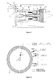
Figure 1 is a sectional side view of a gas turbine engine. -
Figure 2 is a schematic drawing of a blade tip timing arrangement. - A
gas turbine engine 10 is shown inFigure 1 and comprises anair intake 12 and apropulsive fan 14 that generates two airflows A and B. Thegas turbine engine 10 comprises, in axial flow A, anintermediate pressure compressor 16, ahigh pressure compressor 18, acombustor 20, ahigh pressure turbine 22, anintermediate pressure turbine 24, alow pressure turbine 26 and anexhaust nozzle 28. Anacelle 30 surrounds thegas turbine engine 10 and defines, in axial flow B, abypass duct 32. -
Figure 2 shows schematically a blade tip timing (BTT) arrangement. A once perrevolution probe 1 monitors the angular position of therotor 2. BTT probes 3 are mounted to a casing (not shown) and provide time of arrival measurements of the blades 4 mounted to therotor 2. For example, therotor 2 and blades 4 arrangement may be thefan 14, one of the stages of the intermediate pressure orhigh pressure compressor high pressure turbine - In an embodiment of the present invention there are nine BTT probes 3 provided which are spaced around at least some of the circumference of the casing and form a reference set xref. Alternatively there may be a different number of probes 3. Preferably the probes 3 are irregularly spaced so that vibrations at different excitation frequencies are captured. An example set of probes may be located at 353.2°, 326.6°, 319.1°, 295.7°, 285.7°, 271.9°, 264.5°, 237.4° and 207.3°, each measured from top dead centre of the
engine 10. - In a first step of the method of the present invention the time of arrival of each of the blades 4 at each probe 3 is measured for one revolution of the
rotor 2. The predicted time of arrival of each blade 4 at each probe 3 may be calculated from the rotational speed of the blade tip and the position of the probe 3. Due to vibration experienced by therotor 2 and/or the blades 4, the measured time of arrival will differ from the predicted time of arrival by a time difference. The vibration may be synchronous, that is it comprises a frequency that is an integer multiple of the rotor speed, or asynchronous, that is it comprises a frequency that is a non-integer multiple of the rotor speed. Synchronous vibration may be caused by mechanical excitation, whereas asynchronous vibration is caused by non-mechanical excitation such as acoustic noise, rotating stall or blade flutter. - The measured times of arrival can be plotted against the angular probe positions and a wave fitted to the points. The wave will be in the form of an offset a0 plus a constant a1 multiplied by a sine component plus another constant a2 multiplied by a cosine component. The amplitude of the fitted wave is thus

rotor 2. Coherence is defined as the correlation of the measured to the predicted times of arrival, and ranges between 0 and 1 inclusive. Amplitude, frequency and coherence are each blade tip parameters that can be derived from the measured times of arrival and the position of each probe 3. The reference blade tip parameter is the amplitude, frequency or coherence derived from the measured times of arrival at each probe 3 in the reference set xref. - The next step in the method of the present invention comprises calculating a reference condition number. One way of calculating it is by forming a matrix having a column for each component of the fitted wave and a row for each probe 3. The angular position of the jth probe 3 in radians is φj. Thus for the nine probes 3 of the reference set xref the matrix has nine rows and three columns thus:

- To calculate the reference condition number, singular value decomposition is applied to the matrix to extract the singular values. The reference condition number is the ratio of the largest to the smallest singular value.
- The steps of the method are repeated for various rotor speeds of interest, from which a multitude of targeted engine orders EO, reference blade tip parameter values and reference condition numbers are derived. The reference mean condition number is calculated by summing the reference condition numbers and dividing by the number of condition numbers (which is the number of targeted engine orders EO).
- The next step of the method of the present invention comprises defining a subset x where x is an integer. Systematically, set x equal to one less than the number of probes 3 in the reference set xref which is eight when there are nine probes 3 in the reference set Xef. Determine all the possible combinations of x probes 3, where order does not matter x
ref Cx . Thus where x=8, there are nine possible combinations. - For each combination, calculate a condition number in the same manner as the reference condition number was calculated. For x=8 the matrix has three columns and eight rows and there is a matrix for each combination. For each combination, a combination mean condition number is calculated by summing the condition numbers for each targeted engine order EO and dividing by the number of condition numbers.
- Once all the combinations have a mean condition number, these are ordered and a predetermined number of combinations are selected based on a comparison of them with the reference mean condition number. For example, the predetermined number may be five so that the five combinations with mean condition number closest to the reference mean condition number are selected.
- For each of the selected combinations a blade tip parameter is derived from the time of arrival measurements and the position of each selected probe 3. The parameter is derived in the same manner as the reference parameter.
- The final step of the method calculates the uncertainty of the blade tip parameter as a percentage of the reference blade tip parameter.
- The method can be iterated for smaller subsets x. It will be understood that for a smaller subset x, the number of combinations x
ref Cx increases. For example, where x=7 there are 36 combinations and where x=6 there are 336 combinations. The minimum permissible number of probes in the subset is calculated as twice the number of simultaneous modes excited plus two. Thus, where only one mode is excited at a time the minimum number of probes xmin is four. - Although the method steps have been described in a particular order, some of the steps may be performed in a different order as will be apparent to the skilled reader. For example, the step of deriving a blade tip parameter could be performed before the step of ordering the combination means and selecting a predetermined number of combinations. This will be more computationally intensive but may be appropriate for some applications of the method of the present invention.
- Advantageously, steps of the method of the present invention can be repeated for each blade tip parameter of interest. Thus the method may initially be performed to determine the uncertainty in amplitude measurements and then be repeated for frequency and/or coherence.
- The method of the present invention can be applied to blade tip timing measurements howsoever obtained. The measurements may be obtained in development or during operational running. Thus it has applications in any bladed rotor in a gas turbine engine for aerospace, marine or industrial use, such as fan blades, compressor stages and turbine stages. It also has potential application for wind and tidal turbines.
Claims (15)
- A method of determining blade tip timing measurement uncertainty comprising:a) measuring time of arrival of each of a set of blades (4) at each of a reference set of stationary probes (3);b) deriving a reference blade tip parameter from the measurements and the position of each of the probes (3);c) calculating a reference condition number from the position of each of the probes (3) and each targeted engine order;d) calculating a reference mean condition number from the reference condition numbers;e) defining an integer subset x and determining all combinations of x probes (3);f) for each combination, calculating a condition number from the position of each probe (3) of the reference set of probes (3) and each targeted engine order;g) for each combination, calculating a combination mean condition number from the combination condition numbers;h) ordering the combination means from step g) relative to the reference mean and selecting a predetermined number of combinations;i) deriving a blade tip parameter from the measurements and the position of each probe (3) of the selected combination; andj) calculating uncertainty of the blade tip parameter for each selected combination as a percentage of the reference blade tip parameter.
- A method as claimed in claim 1 wherein the reference set of probes, xref, comprises nine probes (3).
- A method as claimed in claim 1 or 2 wherein a minimum number of probes xmin is calculated as twice the number of simultaneous modes excited plus two.
- A method as claimed in any preceding claim further comprising a step, between steps 1h) and 1i), of iterating steps 1e), 1f) and 1g) until x has taken every integer between xmin and (Xref-1).
- A method as claimed in any preceding claim wherein the probes (3) are angularly spaced.
- A method as claimed in claim 5 wherein the spacing of the probes (3) is irregular.
- A method as claimed in claim 5 or 6 wherein the spacing of the probes (3) is determined by excitation modes of the blades (4).
- A method as claimed in any preceding claim wherein the blade tip parameter and the reference blade tip parameter comprise the same parameter.
- A method as claimed in claim 8 wherein the parameter comprises one of the group comprising amplitude, frequency and coherence.
- A method as claimed in claim 9 wherein the method is iterated for each parameter.
- A method as claimed in any preceding claim wherein step 1b) and 1i) each comprise:a) subtracting the measured time of arrival from an expected time of arrival to give a time difference;b) calculating a displacement from the time difference and the speed of the blades (4);c) fitting a wave to the displacements having sine and cosine components; andd) deriving the parameter from the wave.
- A method as claimed in claim 11 wherein the sine and cosine components each have argument comprising the targeted engine order multiplied by the angular position of each probe (3).
- A method as claimed in claim 11 or 12 wherein step 1c) and 1f) each comprise:a) forming a matrix having a column for each component of the fitted wave and a row for each probe (3);b) applying singular variable decomposition to the matrix to extract the singular values; andc) setting the condition number to be the ratio of the largest to the smallest of the singular values.
- A rotor assembly comprising a rotor (2), a set of blades (4) mounted to the rotor (2), a casing that surrounds the blades (4), and a processor arranged to perform the method as claimed in any preceding claim.
- A gas turbine engine (10) comprising the rotor assembly as claimed in claim 14.
Applications Claiming Priority (1)
| Application Number | Priority Date | Filing Date | Title |
|---|---|---|---|
| GBGB1203181.1A GB201203181D0 (en) | 2012-02-24 | 2012-02-24 | Blade tip timing uncertainty |
Publications (3)
| Publication Number | Publication Date |
|---|---|
| EP2631617A2 true EP2631617A2 (en) | 2013-08-28 |
| EP2631617A3 EP2631617A3 (en) | 2017-01-04 |
| EP2631617B1 EP2631617B1 (en) | 2020-10-21 |
Family
ID=45991647
Family Applications (1)
| Application Number | Title | Priority Date | Filing Date |
|---|---|---|---|
| EP13152338.3A Not-in-force EP2631617B1 (en) | 2012-02-24 | 2013-01-23 | Blade Tip Timing Uncertainty |
Country Status (3)
| Country | Link |
|---|---|
| US (1) | US9494491B2 (en) |
| EP (1) | EP2631617B1 (en) |
| GB (1) | GB201203181D0 (en) |
Cited By (1)
| Publication number | Priority date | Publication date | Assignee | Title |
|---|---|---|---|---|
| CN109101769A (en) * | 2018-09-20 | 2018-12-28 | 中国人民解放军国防科技大学 | Leaf end timing sensor number determination method based on compressed sensing |
Families Citing this family (6)
| Publication number | Priority date | Publication date | Assignee | Title |
|---|---|---|---|---|
| GB201309623D0 (en) * | 2013-05-30 | 2013-07-10 | Rolls Royce Plc | Blade tip timing |
| US9530209B2 (en) | 2014-01-15 | 2016-12-27 | Siemens Energy, Inc. | Method of determining the location of tip timing sensors during operation |
| US9840935B2 (en) * | 2014-03-31 | 2017-12-12 | United Technologies Corporation | Rotating machinery monitoring system |
| EP3483571B1 (en) | 2017-11-10 | 2020-04-29 | Rolls-Royce Corporation | Displacement determination using optical measurements |
| CN112880811B (en) * | 2021-01-15 | 2022-03-29 | 大连理工大学 | Key-free phase blade tip timing vibration measurement method for fitting moving straight line |
| CN114441125B (en) * | 2021-12-24 | 2022-10-28 | 北京化工大学 | Non-contact type turbine machinery high-rotating-speed blade vibration multi-mode decomposition method |
Family Cites Families (3)
| Publication number | Priority date | Publication date | Assignee | Title |
|---|---|---|---|---|
| GB0811073D0 (en) | 2008-06-18 | 2008-07-23 | Rolls Royce Plc | Timing analysis |
| GB0822859D0 (en) * | 2008-12-16 | 2009-01-21 | Rolls Royce Plc | Timing analysis |
| GB2466817B (en) | 2009-01-09 | 2010-12-08 | Rolls Royce Plc | Determination of blade vibration frequencies and/or amplitudes |
-
2012
- 2012-02-24 GB GBGB1203181.1A patent/GB201203181D0/en not_active Ceased
-
2013
- 2013-01-23 EP EP13152338.3A patent/EP2631617B1/en not_active Not-in-force
- 2013-01-23 US US13/747,959 patent/US9494491B2/en not_active Expired - Fee Related
Cited By (1)
| Publication number | Priority date | Publication date | Assignee | Title |
|---|---|---|---|---|
| CN109101769A (en) * | 2018-09-20 | 2018-12-28 | 中国人民解放军国防科技大学 | Leaf end timing sensor number determination method based on compressed sensing |
Also Published As
| Publication number | Publication date |
|---|---|
| GB201203181D0 (en) | 2012-04-11 |
| EP2631617B1 (en) | 2020-10-21 |
| US20130226518A1 (en) | 2013-08-29 |
| EP2631617A3 (en) | 2017-01-04 |
| US9494491B2 (en) | 2016-11-15 |
Similar Documents
| Publication | Publication Date | Title |
|---|---|---|
| EP2631617B1 (en) | Blade Tip Timing Uncertainty | |
| EP2808497B1 (en) | Blade tip timing | |
| JP5451164B2 (en) | Dual rotor vibration monitoring | |
| KR101718251B1 (en) | Method and system for monitoring rotating blade health | |
| EP2998720A2 (en) | Shaft stiffness | |
| JP5073533B2 (en) | How to detect damage to engine bearings | |
| US9016132B2 (en) | Rotating blade analysis | |
| EP2781897B1 (en) | Blade tip timing | |
| CN109813423B (en) | Method and device for monitoring vibration displacement of turbine mechanical blade | |
| EP2818647B1 (en) | Blade tip timing system and method of analysing blade tip displacement | |
| EP2808498B1 (en) | Method of analysing blade tip timing and a displacement system | |
| CN113404555B (en) | Blade natural frequency identification method based on multiple blade end timing sensors | |
| CN116878652B (en) | Blade tip timing high-order vibration identification method and system based on blade tip acceleration | |
| Ji-wang et al. | Blade tip-timing technology with multiple reference phases for online monitoring of high-speed blades under variable-speed operation | |
| JP2015125146A (en) | Methods and systems to monitor health of rotor blades | |
| US10168306B2 (en) | Time reference derivation from time of arrival measurements | |
| Bornassi et al. | Blade synchronous vibration measurements of a new upgraded heavy duty gas turbine MGT-70 (3) by using tip-timing method | |
| Mileshin et al. | Numerical and experimental analysis of radial clearance influence on rotor and stator clocking effect by example of model high loaded two stage compressor | |
| JP2015125147A (en) | Method and system for monitoring the health of a rotor blade | |
| EP3012439B1 (en) | Method to determine inertia in a shaft system | |
| CN111174903B (en) | A kind of diagnosing method of turbine mechanical failure | |
| JP7169084B2 (en) | Condition monitoring device and condition monitoring system | |
| Zhang et al. | Characterization of crack on the outer edge of the disk based on blade tip timing technology | |
| Cox et al. | Using Gas Turbine Engine Casing Accelerometer Measurements for Rotor Blade Health Monitoring | |
| US20140188430A1 (en) | System and method for monitoring health of airfoils |
Legal Events
| Date | Code | Title | Description |
|---|---|---|---|
| PUAI | Public reference made under article 153(3) epc to a published international application that has entered the european phase |
Free format text: ORIGINAL CODE: 0009012 |
|
| AK | Designated contracting states |
Kind code of ref document: A2 Designated state(s): AL AT BE BG CH CY CZ DE DK EE ES FI FR GB GR HR HU IE IS IT LI LT LU LV MC MK MT NL NO PL PT RO RS SE SI SK SM TR |
|
| AX | Request for extension of the european patent |
Extension state: BA ME |
|
| RAP1 | Party data changed (applicant data changed or rights of an application transferred) |
Owner name: ROLLS-ROYCE PLC |
|
| PUAL | Search report despatched |
Free format text: ORIGINAL CODE: 0009013 |
|
| AK | Designated contracting states |
Kind code of ref document: A3 Designated state(s): AL AT BE BG CH CY CZ DE DK EE ES FI FR GB GR HR HU IE IS IT LI LT LU LV MC MK MT NL NO PL PT RO RS SE SI SK SM TR |
|
| AX | Request for extension of the european patent |
Extension state: BA ME |
|
| RIC1 | Information provided on ipc code assigned before grant |
Ipc: G01H 1/00 20060101AFI20161130BHEP Ipc: G01M 15/14 20060101ALI20161130BHEP |
|
| STAA | Information on the status of an ep patent application or granted ep patent |
Free format text: STATUS: REQUEST FOR EXAMINATION WAS MADE |
|
| 17P | Request for examination filed |
Effective date: 20170620 |
|
| RBV | Designated contracting states (corrected) |
Designated state(s): AL AT BE BG CH CY CZ DE DK EE ES FI FR GB GR HR HU IE IS IT LI LT LU LV MC MK MT NL NO PL PT RO RS SE SI SK SM TR |
|
| RAP1 | Party data changed (applicant data changed or rights of an application transferred) |
Owner name: ROLLS-ROYCE PLC |
|
| GRAP | Despatch of communication of intention to grant a patent |
Free format text: ORIGINAL CODE: EPIDOSNIGR1 |
|
| STAA | Information on the status of an ep patent application or granted ep patent |
Free format text: STATUS: GRANT OF PATENT IS INTENDED |
|
| GRAS | Grant fee paid |
Free format text: ORIGINAL CODE: EPIDOSNIGR3 |
|
| GRAA | (expected) grant |
Free format text: ORIGINAL CODE: 0009210 |
|
| STAA | Information on the status of an ep patent application or granted ep patent |
Free format text: STATUS: THE PATENT HAS BEEN GRANTED |
|
| INTG | Intention to grant announced |
Effective date: 20200824 |
|
| AK | Designated contracting states |
Kind code of ref document: B1 Designated state(s): AL AT BE BG CH CY CZ DE DK EE ES FI FR GB GR HR HU IE IS IT LI LT LU LV MC MK MT NL NO PL PT RO RS SE SI SK SM TR |
|
| REG | Reference to a national code |
Ref country code: GB Ref legal event code: FG4D |
|
| REG | Reference to a national code |
Ref country code: CH Ref legal event code: EP |
|
| REG | Reference to a national code |
Ref country code: IE Ref legal event code: FG4D |
|
| REG | Reference to a national code |
Ref country code: DE Ref legal event code: R096 Ref document number: 602013073393 Country of ref document: DE |
|
| REG | Reference to a national code |
Ref country code: AT Ref legal event code: REF Ref document number: 1326288 Country of ref document: AT Kind code of ref document: T Effective date: 20201115 |
|
| REG | Reference to a national code |
Ref country code: AT Ref legal event code: MK05 Ref document number: 1326288 Country of ref document: AT Kind code of ref document: T Effective date: 20201021 |
|
| REG | Reference to a national code |
Ref country code: NL Ref legal event code: MP Effective date: 20201021 |
|
| PG25 | Lapsed in a contracting state [announced via postgrant information from national office to epo] |
Ref country code: FI Free format text: LAPSE BECAUSE OF FAILURE TO SUBMIT A TRANSLATION OF THE DESCRIPTION OR TO PAY THE FEE WITHIN THE PRESCRIBED TIME-LIMIT Effective date: 20201021 Ref country code: RS Free format text: LAPSE BECAUSE OF FAILURE TO SUBMIT A TRANSLATION OF THE DESCRIPTION OR TO PAY THE FEE WITHIN THE PRESCRIBED TIME-LIMIT Effective date: 20201021 Ref country code: NL Free format text: LAPSE BECAUSE OF FAILURE TO SUBMIT A TRANSLATION OF THE DESCRIPTION OR TO PAY THE FEE WITHIN THE PRESCRIBED TIME-LIMIT Effective date: 20201021 Ref country code: PT Free format text: LAPSE BECAUSE OF FAILURE TO SUBMIT A TRANSLATION OF THE DESCRIPTION OR TO PAY THE FEE WITHIN THE PRESCRIBED TIME-LIMIT Effective date: 20210222 Ref country code: NO Free format text: LAPSE BECAUSE OF FAILURE TO SUBMIT A TRANSLATION OF THE DESCRIPTION OR TO PAY THE FEE WITHIN THE PRESCRIBED TIME-LIMIT Effective date: 20210121 Ref country code: GR Free format text: LAPSE BECAUSE OF FAILURE TO SUBMIT A TRANSLATION OF THE DESCRIPTION OR TO PAY THE FEE WITHIN THE PRESCRIBED TIME-LIMIT Effective date: 20210122 |
|
| REG | Reference to a national code |
Ref country code: LT Ref legal event code: MG4D |
|
| PG25 | Lapsed in a contracting state [announced via postgrant information from national office to epo] |
Ref country code: PL Free format text: LAPSE BECAUSE OF FAILURE TO SUBMIT A TRANSLATION OF THE DESCRIPTION OR TO PAY THE FEE WITHIN THE PRESCRIBED TIME-LIMIT Effective date: 20201021 Ref country code: IS Free format text: LAPSE BECAUSE OF FAILURE TO SUBMIT A TRANSLATION OF THE DESCRIPTION OR TO PAY THE FEE WITHIN THE PRESCRIBED TIME-LIMIT Effective date: 20210221 Ref country code: LV Free format text: LAPSE BECAUSE OF FAILURE TO SUBMIT A TRANSLATION OF THE DESCRIPTION OR TO PAY THE FEE WITHIN THE PRESCRIBED TIME-LIMIT Effective date: 20201021 Ref country code: SE Free format text: LAPSE BECAUSE OF FAILURE TO SUBMIT A TRANSLATION OF THE DESCRIPTION OR TO PAY THE FEE WITHIN THE PRESCRIBED TIME-LIMIT Effective date: 20201021 Ref country code: ES Free format text: LAPSE BECAUSE OF FAILURE TO SUBMIT A TRANSLATION OF THE DESCRIPTION OR TO PAY THE FEE WITHIN THE PRESCRIBED TIME-LIMIT Effective date: 20201021 Ref country code: AT Free format text: LAPSE BECAUSE OF FAILURE TO SUBMIT A TRANSLATION OF THE DESCRIPTION OR TO PAY THE FEE WITHIN THE PRESCRIBED TIME-LIMIT Effective date: 20201021 Ref country code: BG Free format text: LAPSE BECAUSE OF FAILURE TO SUBMIT A TRANSLATION OF THE DESCRIPTION OR TO PAY THE FEE WITHIN THE PRESCRIBED TIME-LIMIT Effective date: 20210121 |
|
| PG25 | Lapsed in a contracting state [announced via postgrant information from national office to epo] |
Ref country code: HR Free format text: LAPSE BECAUSE OF FAILURE TO SUBMIT A TRANSLATION OF THE DESCRIPTION OR TO PAY THE FEE WITHIN THE PRESCRIBED TIME-LIMIT Effective date: 20201021 |
|
| REG | Reference to a national code |
Ref country code: DE Ref legal event code: R097 Ref document number: 602013073393 Country of ref document: DE |
|
| PG25 | Lapsed in a contracting state [announced via postgrant information from national office to epo] |
Ref country code: SK Free format text: LAPSE BECAUSE OF FAILURE TO SUBMIT A TRANSLATION OF THE DESCRIPTION OR TO PAY THE FEE WITHIN THE PRESCRIBED TIME-LIMIT Effective date: 20201021 Ref country code: RO Free format text: LAPSE BECAUSE OF FAILURE TO SUBMIT A TRANSLATION OF THE DESCRIPTION OR TO PAY THE FEE WITHIN THE PRESCRIBED TIME-LIMIT Effective date: 20201021 Ref country code: LT Free format text: LAPSE BECAUSE OF FAILURE TO SUBMIT A TRANSLATION OF THE DESCRIPTION OR TO PAY THE FEE WITHIN THE PRESCRIBED TIME-LIMIT Effective date: 20201021 Ref country code: CZ Free format text: LAPSE BECAUSE OF FAILURE TO SUBMIT A TRANSLATION OF THE DESCRIPTION OR TO PAY THE FEE WITHIN THE PRESCRIBED TIME-LIMIT Effective date: 20201021 Ref country code: EE Free format text: LAPSE BECAUSE OF FAILURE TO SUBMIT A TRANSLATION OF THE DESCRIPTION OR TO PAY THE FEE WITHIN THE PRESCRIBED TIME-LIMIT Effective date: 20201021 Ref country code: SM Free format text: LAPSE BECAUSE OF FAILURE TO SUBMIT A TRANSLATION OF THE DESCRIPTION OR TO PAY THE FEE WITHIN THE PRESCRIBED TIME-LIMIT Effective date: 20201021 |
|
| PLBE | No opposition filed within time limit |
Free format text: ORIGINAL CODE: 0009261 |
|
| STAA | Information on the status of an ep patent application or granted ep patent |
Free format text: STATUS: NO OPPOSITION FILED WITHIN TIME LIMIT |
|
| PG25 | Lapsed in a contracting state [announced via postgrant information from national office to epo] |
Ref country code: DK Free format text: LAPSE BECAUSE OF FAILURE TO SUBMIT A TRANSLATION OF THE DESCRIPTION OR TO PAY THE FEE WITHIN THE PRESCRIBED TIME-LIMIT Effective date: 20201021 Ref country code: MC Free format text: LAPSE BECAUSE OF FAILURE TO SUBMIT A TRANSLATION OF THE DESCRIPTION OR TO PAY THE FEE WITHIN THE PRESCRIBED TIME-LIMIT Effective date: 20201021 |
|
| REG | Reference to a national code |
Ref country code: CH Ref legal event code: PL |
|
| 26N | No opposition filed |
Effective date: 20210722 |
|
| PG25 | Lapsed in a contracting state [announced via postgrant information from national office to epo] |
Ref country code: LU Free format text: LAPSE BECAUSE OF NON-PAYMENT OF DUE FEES Effective date: 20210123 |
|
| REG | Reference to a national code |
Ref country code: BE Ref legal event code: MM Effective date: 20210131 |
|
| PG25 | Lapsed in a contracting state [announced via postgrant information from national office to epo] |
Ref country code: IT Free format text: LAPSE BECAUSE OF FAILURE TO SUBMIT A TRANSLATION OF THE DESCRIPTION OR TO PAY THE FEE WITHIN THE PRESCRIBED TIME-LIMIT Effective date: 20201021 Ref country code: AL Free format text: LAPSE BECAUSE OF FAILURE TO SUBMIT A TRANSLATION OF THE DESCRIPTION OR TO PAY THE FEE WITHIN THE PRESCRIBED TIME-LIMIT Effective date: 20201021 |
|
| PG25 | Lapsed in a contracting state [announced via postgrant information from national office to epo] |
Ref country code: CH Free format text: LAPSE BECAUSE OF NON-PAYMENT OF DUE FEES Effective date: 20210131 Ref country code: SI Free format text: LAPSE BECAUSE OF FAILURE TO SUBMIT A TRANSLATION OF THE DESCRIPTION OR TO PAY THE FEE WITHIN THE PRESCRIBED TIME-LIMIT Effective date: 20201021 Ref country code: LI Free format text: LAPSE BECAUSE OF NON-PAYMENT OF DUE FEES Effective date: 20210131 |
|
| PG25 | Lapsed in a contracting state [announced via postgrant information from national office to epo] |
Ref country code: IE Free format text: LAPSE BECAUSE OF NON-PAYMENT OF DUE FEES Effective date: 20210123 |
|
| PG25 | Lapsed in a contracting state [announced via postgrant information from national office to epo] |
Ref country code: IS Free format text: LAPSE BECAUSE OF FAILURE TO SUBMIT A TRANSLATION OF THE DESCRIPTION OR TO PAY THE FEE WITHIN THE PRESCRIBED TIME-LIMIT Effective date: 20210221 |
|
| PG25 | Lapsed in a contracting state [announced via postgrant information from national office to epo] |
Ref country code: BE Free format text: LAPSE BECAUSE OF NON-PAYMENT OF DUE FEES Effective date: 20210131 |
|
| PG25 | Lapsed in a contracting state [announced via postgrant information from national office to epo] |
Ref country code: HU Free format text: LAPSE BECAUSE OF FAILURE TO SUBMIT A TRANSLATION OF THE DESCRIPTION OR TO PAY THE FEE WITHIN THE PRESCRIBED TIME-LIMIT; INVALID AB INITIO Effective date: 20130123 |
|
| PGFP | Annual fee paid to national office [announced via postgrant information from national office to epo] |
Ref country code: DE Payment date: 20230127 Year of fee payment: 11 |
|
| PG25 | Lapsed in a contracting state [announced via postgrant information from national office to epo] |
Ref country code: CY Free format text: LAPSE BECAUSE OF FAILURE TO SUBMIT A TRANSLATION OF THE DESCRIPTION OR TO PAY THE FEE WITHIN THE PRESCRIBED TIME-LIMIT Effective date: 20201021 |
|
| P01 | Opt-out of the competence of the unified patent court (upc) registered |
Effective date: 20230528 |
|
| PG25 | Lapsed in a contracting state [announced via postgrant information from national office to epo] |
Ref country code: MK Free format text: LAPSE BECAUSE OF FAILURE TO SUBMIT A TRANSLATION OF THE DESCRIPTION OR TO PAY THE FEE WITHIN THE PRESCRIBED TIME-LIMIT Effective date: 20201021 |
|
| PGFP | Annual fee paid to national office [announced via postgrant information from national office to epo] |
Ref country code: GB Payment date: 20240123 Year of fee payment: 12 |
|
| PGFP | Annual fee paid to national office [announced via postgrant information from national office to epo] |
Ref country code: FR Payment date: 20240125 Year of fee payment: 12 |
|
| PG25 | Lapsed in a contracting state [announced via postgrant information from national office to epo] |
Ref country code: TR Free format text: LAPSE BECAUSE OF FAILURE TO SUBMIT A TRANSLATION OF THE DESCRIPTION OR TO PAY THE FEE WITHIN THE PRESCRIBED TIME-LIMIT Effective date: 20201021 |
|
| REG | Reference to a national code |
Ref country code: DE Ref legal event code: R119 Ref document number: 602013073393 Country of ref document: DE |
|
| PG25 | Lapsed in a contracting state [announced via postgrant information from national office to epo] |
Ref country code: MT Free format text: LAPSE BECAUSE OF FAILURE TO SUBMIT A TRANSLATION OF THE DESCRIPTION OR TO PAY THE FEE WITHIN THE PRESCRIBED TIME-LIMIT Effective date: 20201021 |
|
| PG25 | Lapsed in a contracting state [announced via postgrant information from national office to epo] |
Ref country code: DE Free format text: LAPSE BECAUSE OF NON-PAYMENT OF DUE FEES Effective date: 20240801 |
|
| PG25 | Lapsed in a contracting state [announced via postgrant information from national office to epo] |
Ref country code: DE Free format text: LAPSE BECAUSE OF NON-PAYMENT OF DUE FEES Effective date: 20240801 |
|
| GBPC | Gb: european patent ceased through non-payment of renewal fee |
Effective date: 20250123 |
|
| PG25 | Lapsed in a contracting state [announced via postgrant information from national office to epo] |
Ref country code: GB Free format text: LAPSE BECAUSE OF NON-PAYMENT OF DUE FEES Effective date: 20250123 |
|
| PG25 | Lapsed in a contracting state [announced via postgrant information from national office to epo] |
Ref country code: FR Free format text: LAPSE BECAUSE OF NON-PAYMENT OF DUE FEES Effective date: 20250131 |