EP2631576A2 - Door of Household Appliance and Refrigerator including the Door - Google Patents
Door of Household Appliance and Refrigerator including the Door Download PDFInfo
- Publication number
- EP2631576A2 EP2631576A2 EP13156263.9A EP13156263A EP2631576A2 EP 2631576 A2 EP2631576 A2 EP 2631576A2 EP 13156263 A EP13156263 A EP 13156263A EP 2631576 A2 EP2631576 A2 EP 2631576A2
- Authority
- EP
- European Patent Office
- Prior art keywords
- door
- household appliance
- disposed
- refrigerator
- power supply
- Prior art date
- Legal status (The legal status is an assumption and is not a legal conclusion. Google has not performed a legal analysis and makes no representation as to the accuracy of the status listed.)
- Withdrawn
Links
Images


Classifications
-
- F—MECHANICAL ENGINEERING; LIGHTING; HEATING; WEAPONS; BLASTING
- F25—REFRIGERATION OR COOLING; COMBINED HEATING AND REFRIGERATION SYSTEMS; HEAT PUMP SYSTEMS; MANUFACTURE OR STORAGE OF ICE; LIQUEFACTION SOLIDIFICATION OF GASES
- F25D—REFRIGERATORS; COLD ROOMS; ICE-BOXES; COOLING OR FREEZING APPARATUS NOT OTHERWISE PROVIDED FOR
- F25D23/00—General constructional features
- F25D23/02—Doors; Covers
-
- F—MECHANICAL ENGINEERING; LIGHTING; HEATING; WEAPONS; BLASTING
- F25—REFRIGERATION OR COOLING; COMBINED HEATING AND REFRIGERATION SYSTEMS; HEAT PUMP SYSTEMS; MANUFACTURE OR STORAGE OF ICE; LIQUEFACTION SOLIDIFICATION OF GASES
- F25B—REFRIGERATION MACHINES, PLANTS OR SYSTEMS; COMBINED HEATING AND REFRIGERATION SYSTEMS; HEAT PUMP SYSTEMS
- F25B27/00—Machines, plants or systems, using particular sources of energy
- F25B27/002—Machines, plants or systems, using particular sources of energy using solar energy
- F25B27/005—Machines, plants or systems, using particular sources of energy using solar energy in compression type systems
-
- F—MECHANICAL ENGINEERING; LIGHTING; HEATING; WEAPONS; BLASTING
- F25—REFRIGERATION OR COOLING; COMBINED HEATING AND REFRIGERATION SYSTEMS; HEAT PUMP SYSTEMS; MANUFACTURE OR STORAGE OF ICE; LIQUEFACTION SOLIDIFICATION OF GASES
- F25D—REFRIGERATORS; COLD ROOMS; ICE-BOXES; COOLING OR FREEZING APPARATUS NOT OTHERWISE PROVIDED FOR
- F25D2400/00—General features of, or devices for refrigerators, cold rooms, ice-boxes, or for cooling or freezing apparatus not covered by any other subclass
- F25D2400/40—Refrigerating devices characterised by electrical wiring
-
- Y—GENERAL TAGGING OF NEW TECHNOLOGICAL DEVELOPMENTS; GENERAL TAGGING OF CROSS-SECTIONAL TECHNOLOGIES SPANNING OVER SEVERAL SECTIONS OF THE IPC; TECHNICAL SUBJECTS COVERED BY FORMER USPC CROSS-REFERENCE ART COLLECTIONS [XRACs] AND DIGESTS
- Y02—TECHNOLOGIES OR APPLICATIONS FOR MITIGATION OR ADAPTATION AGAINST CLIMATE CHANGE
- Y02B—CLIMATE CHANGE MITIGATION TECHNOLOGIES RELATED TO BUILDINGS, e.g. HOUSING, HOUSE APPLIANCES OR RELATED END-USER APPLICATIONS
- Y02B10/00—Integration of renewable energy sources in buildings
- Y02B10/20—Solar thermal
Definitions
- the present invention relates to a door of a household appliance, and more particularly to a door of a household appliance having an independent power supply device and a refrigerator including the door.
- a refrigerator is used and well known as a household appliance.
- a refrigerator includes a refrigerator main body and a door connected to the refrigerator main body.
- the door is used for closing the opening portion of the refrigerator main body and is installed on door hinge portions of upper and lower doors in a rotatable manner.
- a wire from inside a refrigerator main body is required to connect the door through one of the upper and lower door hinges to provide power source.
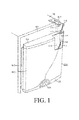
- FIG. 1 is a perspective view of the wiring structure of a refrigerator door 100 in the prior art.
- the refrigerator door 100 is used for open and closing one storage compartment 101 of a refrigerator.
- the storage compartment 101 may be a refrigerator compartment or a freezer compartment.
- a thermal insulation layer 106 made of rigid polyurethane is foam-formed in the space formed of a door front-face material 102, a door rear-face material 103 and upper and lower door covers 104 and 105.
- a display and operation panel 108 used for indicating refrigerator internal conditions such as refrigerator storage compartment temperature or used for operating the refrigerator is disposed at the surface of the door body of the refrigerator door 100, and to arrange wires from the refrigerator body 110 to the display and operation panel 108, a wire bundle 111 is guided into the door 100 through the upper-side door hinge portion 107.
- the wire bundle 111 is required to pass through a hinge pin 112 protruding under the door hinge portion, a bolt hole 113 inserted in the hinge pin 112 and disposed on the upper-side door cover 104, a bushing 114 for protecting the wire bundle 111 and a thermal insulation layer 106 in sequence.
- a sealing tape 115 used for sealing the polyurethane material of the thermal insulation layer 106 is wound at the front end of the bushing 114, and a socket 116 is attached at the front end of the wire bundle 111.
- the number of the wire bundles 111 passing through the bolt hole 113 should not be too large, and in common three-door and two-door refrigerators having a display and operation panel 108 nowadays, the display and operation panel 108 is disposed on the upper door only, and the parameter conditions of the middle door and lower door need to be sent to the display and operation panel 108 on the upper door through another wire bundle hinged between doors, and the circuit is complicated. If a display portion also needs to be disposed on the middle door and the lower door, the number of the wire bundles 111 passing through the bolt hole 113 multiplies, and even though the bolt hole 113 is capable of receiving the wire bundles, a failure occurs easily due to wire crowding.
- the objective of the present invention is to provide a door of a household appliance and a refrigerator including the door, so as to effectively solve the problem that a failure occurs easily as a large number of wire bundles pass through a hinge in the prior art.
- the present invention provides a door of a household appliance, in which an electric member is disposed on the door, and a power supply device electrically connected to the electric member is disposed on the door; by directly disposing the power supply device on the door, the supply by the power source in a main body of the household appliance is not required, and the wire bundle for supplying power to the electric member no longer needs to pass through the hinge, so that the structure of the household appliance is simplified, the probability of failure occurrence is reduced, and the reliability is increased.
- the power supply device is disposed on the door in a pluggable manner, so that the power supply device is capable of being removed at any time if necessary, for example, an external power supply device or a power supply device is aged and needs to be replaced.
- a recess is disposed on a lining of the door, and the power supply device is located in the recess, so that a user replaces the power supply device or unplugs the power supply device for recharging as demanded.
- the power supply device is disposed in an intermediate space defined between a panel and a lining of the door and is closed by one of an upper side cover and a lower side cover forming upper and lower side walls of the door; in the premise of making the power supply device pluggable for a user, no additional storage space is occupied and the power supply device is desirably concealed, thereby enhancing the visual effect of the door.
- the power supply device is a first rechargeable battery, and it is convenient and inexpensive to directly use a rechargeable battery as the power supply device.
- the power supply device includes a solar cell panel, a control conversion module, and a second rechargeable battery.
- the control conversion module connects the solar cell panel and the second rechargeable battery and recharges the rechargeable battery through the solar cell panel, making it more convenient for a user, which is energy conservative and environmentally friendly, and also the use of free solar energy is also economic in a long run.
- the solar cell panel covers an overlying plate of the door to absorb light energy, which not only provides an area required for placing the solar cell panel, but also enhances the appearance of the refrigerator door.
- a recess is provided on a lining of the door, and the second rechargeable battery is disposed in the recess, making it more convenient for a user to replace the power supply device as demanded.
- the second rechargeable battery is disposed in a pluggable manner in a gap between a panel and a lining of the door and is closed by an upper side cover or a lower side cover forming upper and lower side walls of the door, or is disposed in a pluggable manner on a lining of the door; in the premise of making the power supply device pluggable for a user, no additional storage space is occupied and the power supply device is desirably concealed, thereby enhancing the visual effect of the door.
- the electric member includes a display portion and an illumination portion.
- the door and a main body of the refrigerator are respectively supplied with power by different power supply devices, and by separately supplying power to the door, it is avoided that the wire bundle for supplying power passes through the hinge of the door, and the probability of failure occurrence is reduced.
- the present invention further provides a refrigerator, the refrigerator includes the door according to at least one of claims 1 to 11, in which the wire bundle for supplying power to a display portion does not pass through the hinge, so that the structure of the refrigerator is simplified and it becomes possible that a display portion is disposed on every door on, for example, a three-door refrigerator.
- a refrigerator includes: a main body, the main body is disposed with three storage compartments, a front opening of each storage compartment is opened or closed respectively by an upper door 10, a middle door 17, and a lower door 18, the upper door 10, the middle door 17, the lower door 18 are hinged to a front surface of the main body 20 in a rotatable manner, and the main body 20 and the upper door 10, the middle door 17, and the lower door 18 together form the appearance of the refrigerator.
- the refrigerator provides cold air through evaporators (not shown) in a refrigeration cycle, and the evaporators are respectively installed on the inner surface at the rear portion of the storage compartment, so as to store the objects in the storage compartment in a refrigerating or freezing state.
- the power for the evaporator, condenser, compressor, and the like in the main body is supplied by an external power source by means of the connection to the external power source with a plug.
- the upper door 10 closes a refrigerator compartment
- the middle door 17 closes a soft freezing compartment
- the lower door 18 closes a freezer compartment, in which a display portion 12 is disposed on the upper door 10, and in practical operations, a control panel is usually disposed at one side of the display portion 12 of the upper door 10, and only a display portion 12 is disposed on the middle door 17 and the lower door 18.
- the upper door 10 includes a non-cutting-formed lining plate produced from a plastic plate, one overlying plate 22 connected to the lining plate to form the door main body and used as an outer surface layer, and an insulation layer 21 foam-formed in an intermediate space 23 defined between the lining 25 and the overlying plate 22, a display region is arranged on the surface of the overlying plate 22, the display portion 12 is disposed and is used for displaying information related to the operation of the refrigerator, for example, used for displaying the temperature and humidity data of the refrigerator collected by, for example, a temperature sensor and a humidity sensor disposed inside the refrigerator, and the display portion is preferably an LCD display.
- a solar cell panel 11 covers the overlying plate 22 of the refrigerator and the solar cell panel 11 includes two parts separately arranged at two sides of the display portion 12. In the embodiment, the solar cell panel 11 approximately occupies two thirds of the area of the overlying plate 22 of the refrigerator.
- the portion of each solar cell panel 11 is connected to a control conversion module. As shown in FIG. 4 , the control conversion module and the rechargeable battery 13 are together placed in an intermediate space 23 defined between the overlying plate 22 and a lining 25 of the door, in which, for ease of plugging and unplugging of the rechargeable battery 13, the placement position is near the bottom edge of the door, and are closed by a lower side cover 14 forming the lower side wall of the door.
- the solar cell panel 11 absorbs the sun's light energy, and the light energy is converted into electrical energy through the control conversion module and stored in the rechargeable battery 13 for use by the display portion 12.
- the rechargeable battery is placed at an upper edge near the door and is closed by an upper side cover 15 forming the upper side wall of the door.
- the upper side cover 15 or the lower side cover 14 can be easily removed to make it convenient to plug and unplug the rechargeable battery 13, and it can also be selected to replace an aged rechargeable battery 13 with a new battery.
- an illumination device can also be disposed on the door to make it convenient for a user to fetch food or beverage placed on the door.
- the illumination device is preferably an LED illumination lamp, and the illumination device is also connected to the rechargeable battery 13 and supplied with power by the rechargeable battery 13.
- the electric member in the embodiment includes a display portion 12 and an illumination portion.
- the refrigerator is placed indoors.
- a thin film amorphous silicon solar battery is used, and a typical 7% conversion efficiency a-Si thin film solar battery is taken as an example, the peak power of which is 10 w/m 2 .
- the area is about 0.3 m 2
- the solar cell panel approximately occupies two thirds of the area of the overlying plate of the refrigerator, the area of the solar cell panel is 0.2 m 2 .
- the power capable of being supplied each day is large than the total power consumption each day, that is, the area of the door body of an existing refrigerator can totally meet the electric demand of the door body of a refrigerator.
- the power supply device is located on the refrigerator door and separately supplies power to the refrigerator door, so as to eliminate wires connected to the main body of the refrigerator through the upper door hinge, so that the wire that passes through the hinge is only a control wire, thereby avoiding the problem that an error occurs easily due to wire crowding. As only a display portion is disposed on the middle door and the lower door and a control portion is not disposed, no wire passes through the middle door hinge and the lower door hinge.
Landscapes
- Engineering & Computer Science (AREA)
- Chemical & Material Sciences (AREA)
- Combustion & Propulsion (AREA)
- Physics & Mathematics (AREA)
- Mechanical Engineering (AREA)
- Thermal Sciences (AREA)
- General Engineering & Computer Science (AREA)
- Devices That Are Associated With Refrigeration Equipment (AREA)
- Cold Air Circulating Systems And Constructional Details In Refrigerators (AREA)
- Refrigerator Housings (AREA)
Abstract
Description
- The present invention relates to a door of a household appliance, and more particularly to a door of a household appliance having an independent power supply device and a refrigerator including the door.
- A refrigerator is used and well known as a household appliance. A refrigerator includes a refrigerator main body and a door connected to the refrigerator main body. The door is used for closing the opening portion of the refrigerator main body and is installed on door hinge portions of upper and lower doors in a rotatable manner. For a refrigerator having a door disposed with a display screen or operation panel, a wire from inside a refrigerator main body is required to connect the door through one of the upper and lower door hinges to provide power source.
-
FIG. 1 is a perspective view of the wiring structure of a refrigerator door 100 in the prior art. The refrigerator door 100 is used for open and closing onestorage compartment 101 of a refrigerator. Thestorage compartment 101 may be a refrigerator compartment or a freezer compartment. In the refrigerator door, athermal insulation layer 106 made of rigid polyurethane is foam-formed in the space formed of a door front-face material 102, a door rear-face material 103 and upper andlower door covers 104 and 105. A display andoperation panel 108 used for indicating refrigerator internal conditions such as refrigerator storage compartment temperature or used for operating the refrigerator is disposed at the surface of the door body of the refrigerator door 100, and to arrange wires from the refrigerator body 110 to the display andoperation panel 108, a wire bundle 111 is guided into the door 100 through the upper-sidedoor hinge portion 107. - To be connected to the display and
operation panel 108 through thedoor hinge portion 107, the wire bundle 111 is required to pass through a hinge pin 112 protruding under the door hinge portion, abolt hole 113 inserted in the hinge pin 112 and disposed on the upper-side door cover 104, abushing 114 for protecting the wire bundle 111 and athermal insulation layer 106 in sequence. A sealing tape 115 used for sealing the polyurethane material of thethermal insulation layer 106 is wound at the front end of thebushing 114, and a socket 116 is attached at the front end of the wire bundle 111. As being limited by the hole diameters of the hinge pin 112 and thebolt hole 113, the number of the wire bundles 111 passing through thebolt hole 113 should not be too large, and in common three-door and two-door refrigerators having a display andoperation panel 108 nowadays, the display andoperation panel 108 is disposed on the upper door only, and the parameter conditions of the middle door and lower door need to be sent to the display andoperation panel 108 on the upper door through another wire bundle hinged between doors, and the circuit is complicated. If a display portion also needs to be disposed on the middle door and the lower door, the number of the wire bundles 111 passing through thebolt hole 113 multiplies, and even though thebolt hole 113 is capable of receiving the wire bundles, a failure occurs easily due to wire crowding. - The objective of the present invention is to provide a door of a household appliance and a refrigerator including the door, so as to effectively solve the problem that a failure occurs easily as a large number of wire bundles pass through a hinge in the prior art.
- To implement the objectives, the present invention provides a door of a household appliance, in which an electric member is disposed on the door, and a power supply device electrically connected to the electric member is disposed on the door; by directly disposing the power supply device on the door, the supply by the power source in a main body of the household appliance is not required, and the wire bundle for supplying power to the electric member no longer needs to pass through the hinge, so that the structure of the household appliance is simplified, the probability of failure occurrence is reduced, and the reliability is increased.
- Other separate features, or the features that are considered as the characteristics of the present invention in combination with other features, are illustrated in the appended claims.
- Optionally, the power supply device is disposed on the door in a pluggable manner, so that the power supply device is capable of being removed at any time if necessary, for example, an external power supply device or a power supply device is aged and needs to be replaced.
- Optionally, a recess is disposed on a lining of the door, and the power supply device is located in the recess, so that a user replaces the power supply device or unplugs the power supply device for recharging as demanded.
- Optionally, the power supply device is disposed in an intermediate space defined between a panel and a lining of the door and is closed by one of an upper side cover and a lower side cover forming upper and lower side walls of the door; in the premise of making the power supply device pluggable for a user, no additional storage space is occupied and the power supply device is desirably concealed, thereby enhancing the visual effect of the door.
- Optionally, the power supply device is a first rechargeable battery, and it is convenient and inexpensive to directly use a rechargeable battery as the power supply device.
- Optionally, the power supply device includes a solar cell panel, a control conversion module, and a second rechargeable battery. The control conversion module connects the solar cell panel and the second rechargeable battery and recharges the rechargeable battery through the solar cell panel, making it more convenient for a user, which is energy conservative and environmentally friendly, and also the use of free solar energy is also economic in a long run.
- Optionally, the solar cell panel covers an overlying plate of the door to absorb light energy, which not only provides an area required for placing the solar cell panel, but also enhances the appearance of the refrigerator door.
- Optionally, a recess is provided on a lining of the door, and the second rechargeable battery is disposed in the recess, making it more convenient for a user to replace the power supply device as demanded.
- Optionally, the second rechargeable battery is disposed in a pluggable manner in a gap between a panel and a lining of the door and is closed by an upper side cover or a lower side cover forming upper and lower side walls of the door, or is disposed in a pluggable manner on a lining of the door; in the premise of making the power supply device pluggable for a user, no additional storage space is occupied and the power supply device is desirably concealed, thereby enhancing the visual effect of the door.
- Optionally, the electric member includes a display portion and an illumination portion.
- Optionally, the door and a main body of the refrigerator are respectively supplied with power by different power supply devices, and by separately supplying power to the door, it is avoided that the wire bundle for supplying power passes through the hinge of the door, and the probability of failure occurrence is reduced.
- To implement the above objectives, the present invention further provides a refrigerator, the refrigerator includes the door according to at least one of claims 1 to 11, in which the wire bundle for supplying power to a display portion does not pass through the hinge, so that the structure of the refrigerator is simplified and it becomes possible that a display portion is disposed on every door on, for example, a three-door refrigerator.
- The structure of the present invention and other invention objects and beneficial effects will become more apparent and comprehensible through the description of the preferred embodiments with reference to the accompanying drawings.
- To serve as a part of the specification and provide further understanding of the present invention, the accompanying drawings below are provided for illustrating the embodiments of the present invention, which are used together with the specification to illustrate the principles of the present invention.
-
FIG. 1 is a perspective view of the wiring structure of a refrigerator door in the prior art; -
FIG. 2 is a schematic structural view of a door of a household appliance according to an embodiment of the present invention; -
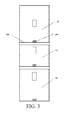
FIG. 3 is a schematic structural view of a door of a household appliance according to another embodiment of the present invention; -
FIG. 4 is a sectional view of a first placement position of a rechargeable battery according to the present invention; and -
FIG. 5 is a sectional view of a second placement position of a rechargeable battery according to the present invention. - The typical embodiments of the present invention are illustrated in detail, the examples of which are shown in the accompanying drawings, and the same drawing labels in all the accompanying drawings indicate the same elements. The embodiments are described with reference to the accompanying drawings to illustrate the present invention.
- A refrigerator according to a preferred embodiment of the present invention includes: a main body, the main body is disposed with three storage compartments, a front opening of each storage compartment is opened or closed respectively by an
upper door 10, amiddle door 17, and alower door 18, theupper door 10, themiddle door 17, thelower door 18 are hinged to a front surface of the main body 20 in a rotatable manner, and the main body 20 and theupper door 10, themiddle door 17, and thelower door 18 together form the appearance of the refrigerator. The refrigerator provides cold air through evaporators (not shown) in a refrigeration cycle, and the evaporators are respectively installed on the inner surface at the rear portion of the storage compartment, so as to store the objects in the storage compartment in a refrigerating or freezing state. The power for the evaporator, condenser, compressor, and the like in the main body is supplied by an external power source by means of the connection to the external power source with a plug. - As shown in
FIG. 2 , in the embodiment, theupper door 10 closes a refrigerator compartment, themiddle door 17 closes a soft freezing compartment, and thelower door 18 closes a freezer compartment, in which a display portion 12 is disposed on theupper door 10, and in practical operations, a control panel is usually disposed at one side of the display portion 12 of theupper door 10, and only a display portion 12 is disposed on themiddle door 17 and thelower door 18. Theupper door 10 includes a non-cutting-formed lining plate produced from a plastic plate, oneoverlying plate 22 connected to the lining plate to form the door main body and used as an outer surface layer, and aninsulation layer 21 foam-formed in anintermediate space 23 defined between thelining 25 and theoverlying plate 22, a display region is arranged on the surface of theoverlying plate 22, the display portion 12 is disposed and is used for displaying information related to the operation of the refrigerator, for example, used for displaying the temperature and humidity data of the refrigerator collected by, for example, a temperature sensor and a humidity sensor disposed inside the refrigerator, and the display portion is preferably an LCD display. - A
solar cell panel 11 covers theoverlying plate 22 of the refrigerator and thesolar cell panel 11 includes two parts separately arranged at two sides of the display portion 12. In the embodiment, thesolar cell panel 11 approximately occupies two thirds of the area of theoverlying plate 22 of the refrigerator. The portion of eachsolar cell panel 11 is connected to a control conversion module. As shown inFIG. 4 , the control conversion module and therechargeable battery 13 are together placed in anintermediate space 23 defined between theoverlying plate 22 and alining 25 of the door, in which, for ease of plugging and unplugging of therechargeable battery 13, the placement position is near the bottom edge of the door, and are closed by alower side cover 14 forming the lower side wall of the door. Thesolar cell panel 11 absorbs the sun's light energy, and the light energy is converted into electrical energy through the control conversion module and stored in therechargeable battery 13 for use by the display portion 12. In another manner, the rechargeable battery is placed at an upper edge near the door and is closed by anupper side cover 15 forming the upper side wall of the door. Theupper side cover 15 or thelower side cover 14 can be easily removed to make it convenient to plug and unplug therechargeable battery 13, and it can also be selected to replace an agedrechargeable battery 13 with a new battery. - In addition, an illumination device can also be disposed on the door to make it convenient for a user to fetch food or beverage placed on the door. The illumination device is preferably an LED illumination lamp, and the illumination device is also connected to the
rechargeable battery 13 and supplied with power by therechargeable battery 13. The electric member in the embodiment includes a display portion 12 and an illumination portion. - In the following, the feasibility of the embodiment is calculated and analyzed more precisely.
- By taking an upper door for a refrigerator compartment that has the highest demand for electric power as an example, the power consumption involved 4 LED lamps, an LCD display and a DOM control module, in which the 4 LED lamps are used for illumination and indication, the power of each LED lamp is 0.5 w, and the total of the 4 is 2 w; the power of the LCD display is 1.5 w, the power of the DOM control module is 1 w, and the loss for the conversion and control circuit of the battery is 20% is also considered, so that the total power consumption required each day is:

- The refrigerator is placed indoors. A thin film amorphous silicon solar battery is used, and a typical 7% conversion efficiency a-Si thin film solar battery is taken as an example, the peak power of which is 10 w/m2. By taking an upper door of a three-door refrigerator having a small area of a brand as an example, the area is about 0.3 m2, and as the solar cell panel approximately occupies two thirds of the area of the overlying plate of the refrigerator, the area of the solar cell panel is 0.2 m2. The power capable of being supplied per day is calculated with 10 hours a day for the time with illumination indoors: 100*0.2*10 = 200 w.
- As can be seen from the above calculation result, the power capable of being supplied each day is large than the total power consumption each day, that is, the area of the door body of an existing refrigerator can totally meet the electric demand of the door body of a refrigerator.
- The power supply device is located on the refrigerator door and separately supplies power to the refrigerator door, so as to eliminate wires connected to the main body of the refrigerator through the upper door hinge, so that the wire that passes through the hinge is only a control wire, thereby avoiding the problem that an error occurs easily due to wire crowding. As only a display portion is disposed on the middle door and the lower door and a control portion is not disposed, no wire passes through the middle door hinge and the lower door hinge.
- The embodiments disclosed in the present invention further include the following three manners:
- 1. As shown in
FIG. 5 , arecess 26 is disposed on a non-cutting formed lining 25 produced from a plastic plate and is used for placing arechargeable battery 13, therechargeable battery 13 may be inserted in therecess 26 and connected to a display portion 12, so as to supply power to thedisplay portion 13. When the electricity is used up, therechargeable battery 13 may also be unplugged from therecess 26 for recharging. In this embodiment, a solar cell panel is not required. As the power required for the door each day is not high, therechargeable battery 13 can be recharged at a relatively long interval, so that compared with the first embodiment, this embodiment saves the cost. - 2. As shown in
FIG. 3 , a solar cell panel is not disposed, arechargeable battery 13 connected to a display portion 12 is placed in a pluggable manner in anintermediate space 23 defined between anoverlying plate 22 and a lining 25 of a door, in which for ease of plugging and unplugging, the placement position is near the upper edge of the door or near the lower edge of the door, and is closed by one of theupper side cover 15 and thelower side cover 14 forming the upper and lower side walls of the door, and inFIG. 3 , therechargeable battery 13 is closed by thelower side cover 14. - 3. A
recess 26 is formed on thelining 25 and is used for placing a pluggablerechargeable battery 24. Asolar cell panel 11 covers anoverlying plate 22 of a refrigerator, a control conversion module is placed at one side of therechargeable battery 24, thesolar cell panel 11 absorbs the sun's light energy, and the light energy is converted into electrical energy through the control conversion module and stored in therechargeable battery 24 for use by thedisplay portion 13. In the embodiment, thesolar cell panel 11 on the door includes two parts separately arranged at two sides of thedisplay portion 13, making the appearance of the refrigerator simple and elegant, and the portion of each solar cell panel is connected to the control conversion module.
Claims (12)
- A door of a household appliance, wherein an electric member (12) is disposed on the door (10), characterized in that a power supply device (11, 13) electrically connected to the electric member (12) is disposed on the door (10).
- The door of a household appliance according to claim 1, characterized in that the power supply device (13) is disposed in the door (10) in a pluggable manner.
- The door of a household appliance according to claim 1 or 2, characterized in that a recess (26) is disposed in a lining (25) of the door, and the power supply device (13) is located in the recess (26).
- The door of a household appliance according to claim 1 or 2, characterized in that the power supply device (13) is disposed in an intermediate space (23) defined between an overlying plate (22) and a lining (25) of the door and is closed by one of an upper side cover (15) and a lower side cover (14) forming upper and lower side walls of the door (10).
- The door of a household appliance according to any one of claims 1 to 4, characterized in that the power supply device is a first rechargeable battery (24).
- The door of a household appliance according to claim 1, characterized in that the power supply device comprises a solar cell panel (11), a control conversion module, and a second rechargeable battery (13), and the control conversion module connects the solar cell panel (11) and the second rechargeable battery (13).
- The door of a household appliance according to claim 6, characterized in that the solar cell panel (11) covers an overlying plate (22) of the door to absorb light energy.
- The door of a household appliance according to claim 6, characterized in that a recess (26) is disposed in a lining (25) of the door, and the second rechargeable battery (13) is located in the recess (26).
- The door of a household appliance according to claim 6, characterized in that the second rechargeable battery (13) is disposed in a pluggable manner in an intermediate space (23) between an overlying plate (22) and a lining (25) of the door and is closed by an upper side cover (15) and a lower side cover (14) forming upper and lower side walls of the door (10), or is disposed on the lining (25) of the door in a pluggable manner.
- The door of a household appliance according to claim 1, characterized in that the electric member (12) comprises a display portion and an illumination portion.
- The door of a household appliance according to claim 1, characterized in that the door (10) and a main body of a refrigerator are respectively supplied with power by different power supply devices.
- A refrigerator, characterized in that the refrigerator comprises at least one door according to one of claims 1 to 11.
Applications Claiming Priority (1)
| Application Number | Priority Date | Filing Date | Title |
|---|---|---|---|
| CN2012100499947A CN103292548A (en) | 2012-02-24 | 2012-02-24 | Door of domestic appliance and refrigerator comprising same |
Publications (2)
| Publication Number | Publication Date |
|---|---|
| EP2631576A2 true EP2631576A2 (en) | 2013-08-28 |
| EP2631576A3 EP2631576A3 (en) | 2015-01-21 |
Family
ID=47750478
Family Applications (1)
| Application Number | Title | Priority Date | Filing Date |
|---|---|---|---|
| EP13156263.9A Withdrawn EP2631576A3 (en) | 2012-02-24 | 2013-02-22 | Door of Household Appliance and Refrigerator including the Door |
Country Status (2)
| Country | Link |
|---|---|
| EP (1) | EP2631576A3 (en) |
| CN (1) | CN103292548A (en) |
Cited By (3)
| Publication number | Priority date | Publication date | Assignee | Title |
|---|---|---|---|---|
| DE102014011592A1 (en) * | 2014-08-01 | 2016-02-04 | Liebherr-Hausgeräte Ochsenhausen GmbH | Fridge and / or freezer |
| EP3306203A4 (en) * | 2015-07-03 | 2018-07-11 | Samsung Electronics Co., Ltd. | Oven |
| US10429124B2 (en) * | 2015-09-01 | 2019-10-01 | Samsung Electronics Co., Ltd. | Refrigerator |
Families Citing this family (1)
| Publication number | Priority date | Publication date | Assignee | Title |
|---|---|---|---|---|
| CN105910374B (en) * | 2016-04-28 | 2017-11-17 | 中山市维诺电器有限公司 | A kind of lower sliding door built-in refrigerator or wine cabinet |
Family Cites Families (7)
| Publication number | Priority date | Publication date | Assignee | Title |
|---|---|---|---|---|
| JP2000257876A (en) * | 1999-03-05 | 2000-09-22 | Toshiba Corp | microwave |
| JP2002243333A (en) * | 2001-02-16 | 2002-08-28 | Matsushita Refrig Co Ltd | Refrigerator |
| CN100417898C (en) * | 2004-04-12 | 2008-09-10 | 乐金电子(天津)电器有限公司 | Refrigerator with separable terminal mounting case |
| JP4620003B2 (en) * | 2006-07-12 | 2011-01-26 | 株式会社東芝 | refrigerator |
| KR100880486B1 (en) * | 2007-10-08 | 2009-01-28 | 엘지전자 주식회사 | Refrigerator |
| DE102008043722A1 (en) * | 2008-11-13 | 2010-05-20 | BSH Bosch und Siemens Hausgeräte GmbH | Household appliance e.g. baking oven, operating arrangement, has portable remote operating unit for operating household appliances, and holder for holding remote operating unit, where holder is integrated into appliance door |
| DE102009000347A1 (en) * | 2009-01-21 | 2010-08-05 | BSH Bosch und Siemens Hausgeräte GmbH | Domestic refrigeration appliance has housing and heat insulating internal space which is arranged within housing, where refrigeration circuit has compressor for cooling internal space |
-
2012
- 2012-02-24 CN CN2012100499947A patent/CN103292548A/en active Pending
-
2013
- 2013-02-22 EP EP13156263.9A patent/EP2631576A3/en not_active Withdrawn
Non-Patent Citations (1)
| Title |
|---|
| None |
Cited By (5)
| Publication number | Priority date | Publication date | Assignee | Title |
|---|---|---|---|---|
| DE102014011592A1 (en) * | 2014-08-01 | 2016-02-04 | Liebherr-Hausgeräte Ochsenhausen GmbH | Fridge and / or freezer |
| EP3306203A4 (en) * | 2015-07-03 | 2018-07-11 | Samsung Electronics Co., Ltd. | Oven |
| US10612789B2 (en) | 2015-07-03 | 2020-04-07 | Samsung Electronics Co., Ltd. | Oven |
| EP3974732A1 (en) * | 2015-07-03 | 2022-03-30 | Samsung Electronics Co., Ltd. | Oven |
| US10429124B2 (en) * | 2015-09-01 | 2019-10-01 | Samsung Electronics Co., Ltd. | Refrigerator |
Also Published As
| Publication number | Publication date |
|---|---|
| CN103292548A (en) | 2013-09-11 |
| EP2631576A3 (en) | 2015-01-21 |
Similar Documents
| Publication | Publication Date | Title |
|---|---|---|
| US10139155B2 (en) | Refrigerator | |
| KR19990064086A (en) | Refrigerator temperature controller | |
| ITMI20000269U1 (en) | REFRIGERATOR FOR THE STORAGE OF FOODS WITH INTERFACE SUPPORTING CLOSING ORGAN FOR THE COMMAND OF ITS OPERATION | |
| CA2573050A1 (en) | Step-down top hinge for refrigerator door with external dispenser | |
| CN102435039B (en) | Door for refrigerator and refrigerator with door | |
| CN102519204A (en) | Bar counter door for refrigerator and refrigerator with same | |
| CN206352927U (en) | Refrigerator and its drawer appliance | |
| CN102494480A (en) | Refrigerator door body and refrigerator with same | |
| JP2012072967A (en) | Refrigerator | |
| CN103292548A (en) | Door of domestic appliance and refrigerator comprising same | |
| US20130092802A1 (en) | Line Extender/Retractor | |
| CN220771509U (en) | Refrigerating and freezing device for storing biological samples | |
| RU2010139321A (en) | REFRIGERATING UNIT WITH MULTIMEDIA TRANSMISSION DEVICE | |
| CN210285315U (en) | Vehicle-mounted mobile cold chain distribution box | |
| KR20210156160A (en) | Refrigerator including a door switch | |
| CN102494457A (en) | Refrigerator | |
| CN218096769U (en) | Refrigerator and junction box thereof | |
| CN108502315A (en) | A kind of visual storage device of ultralow temperature | |
| CN102494483B (en) | Refrigerator door body and refrigerator with same | |
| CN220707813U (en) | Freezer | |
| CN2385285Y (en) | Cooling-storage structure for medical refrigerator | |
| CN222210891U (en) | Refrigerating appliance | |
| CN222651728U (en) | Refrigerating apparatus | |
| CN223928404U (en) | Photovoltaic power supply refrigerator camera and commercial refrigerator | |
| CN219222963U (en) | Multifunctional vehicle-mounted refrigerator |
Legal Events
| Date | Code | Title | Description |
|---|---|---|---|
| PUAI | Public reference made under article 153(3) epc to a published international application that has entered the european phase |
Free format text: ORIGINAL CODE: 0009012 |
|
| AK | Designated contracting states |
Kind code of ref document: A2 Designated state(s): AL AT BE BG CH CY CZ DE DK EE ES FI FR GB GR HR HU IE IS IT LI LT LU LV MC MK MT NL NO PL PT RO RS SE SI SK SM TR |
|
| AX | Request for extension of the european patent |
Extension state: BA ME |
|
| RIN1 | Information on inventor provided before grant (corrected) |
Inventor name: FANG, QINGLEI Inventor name: MU, YONG Inventor name: ZHU, LEI |
|
| PUAL | Search report despatched |
Free format text: ORIGINAL CODE: 0009013 |
|
| AK | Designated contracting states |
Kind code of ref document: A3 Designated state(s): AL AT BE BG CH CY CZ DE DK EE ES FI FR GB GR HR HU IE IS IT LI LT LU LV MC MK MT NL NO PL PT RO RS SE SI SK SM TR |
|
| AX | Request for extension of the european patent |
Extension state: BA ME |
|
| RIC1 | Information provided on ipc code assigned before grant |
Ipc: F25D 23/02 20060101AFI20141212BHEP |
|
| RAP1 | Party data changed (applicant data changed or rights of an application transferred) |
Owner name: BSH HAUSGERAETE GMBH |
|
| 17P | Request for examination filed |
Effective date: 20150721 |
|
| RBV | Designated contracting states (corrected) |
Designated state(s): AL AT BE BG CH CY CZ DE DK EE ES FI FR GB GR HR HU IE IS IT LI LT LU LV MC MK MT NL NO PL PT RO RS SE SI SK SM TR |
|
| STAA | Information on the status of an ep patent application or granted ep patent |
Free format text: STATUS: THE APPLICATION IS DEEMED TO BE WITHDRAWN |
|
| 18D | Application deemed to be withdrawn |
Effective date: 20150722 |