EP2631542A2 - Glow plug - Google Patents
Glow plug Download PDFInfo
- Publication number
- EP2631542A2 EP2631542A2 EP13156421.3A EP13156421A EP2631542A2 EP 2631542 A2 EP2631542 A2 EP 2631542A2 EP 13156421 A EP13156421 A EP 13156421A EP 2631542 A2 EP2631542 A2 EP 2631542A2
- Authority
- EP
- European Patent Office
- Prior art keywords
- seal member
- axis
- thread portion
- housing
- external thread
- Prior art date
- Legal status (The legal status is an assumption and is not a legal conclusion. Google has not performed a legal analysis and makes no representation as to the accuracy of the status listed.)
- Withdrawn
Links
- 238000002485 combustion reaction Methods 0.000 claims abstract description 33
- 230000015572 biosynthetic process Effects 0.000 claims abstract description 16
- 239000011810 insulating material Substances 0.000 claims abstract description 5
- 230000002093 peripheral effect Effects 0.000 claims description 16
- 239000013013 elastic material Substances 0.000 claims description 2
- 239000000919 ceramic Substances 0.000 abstract description 27
- 230000006866 deterioration Effects 0.000 abstract description 9
- 229910052751 metal Inorganic materials 0.000 description 13
- 239000002184 metal Substances 0.000 description 13
- 239000000463 material Substances 0.000 description 5
- XEEYBQQBJWHFJM-UHFFFAOYSA-N Iron Chemical compound [Fe] XEEYBQQBJWHFJM-UHFFFAOYSA-N 0.000 description 4
- 230000006835 compression Effects 0.000 description 4
- 238000007906 compression Methods 0.000 description 4
- 239000000758 substrate Substances 0.000 description 4
- 239000000498 cooling water Substances 0.000 description 3
- 230000007423 decrease Effects 0.000 description 3
- 230000000694 effects Effects 0.000 description 3
- 239000007788 liquid Substances 0.000 description 3
- 239000007769 metal material Substances 0.000 description 3
- 230000003245 working effect Effects 0.000 description 3
- 229910052581 Si3N4 Inorganic materials 0.000 description 2
- 230000008859 change Effects 0.000 description 2
- 229920001973 fluoroelastomer Polymers 0.000 description 2
- 229910052742 iron Inorganic materials 0.000 description 2
- 230000005855 radiation Effects 0.000 description 2
- 230000009467 reduction Effects 0.000 description 2
- 238000007789 sealing Methods 0.000 description 2
- HQVNEWCFYHHQES-UHFFFAOYSA-N silicon nitride Chemical compound N12[Si]34N5[Si]62N3[Si]51N64 HQVNEWCFYHHQES-UHFFFAOYSA-N 0.000 description 2
- 229920002379 silicone rubber Polymers 0.000 description 2
- 239000004945 silicone rubber Substances 0.000 description 2
- 230000037303 wrinkles Effects 0.000 description 2
- ZOKXTWBITQBERF-UHFFFAOYSA-N Molybdenum Chemical compound [Mo] ZOKXTWBITQBERF-UHFFFAOYSA-N 0.000 description 1
- PNEYBMLMFCGWSK-UHFFFAOYSA-N aluminium oxide Inorganic materials [O-2].[O-2].[O-2].[Al+3].[Al+3] PNEYBMLMFCGWSK-UHFFFAOYSA-N 0.000 description 1
- 239000004020 conductor Substances 0.000 description 1
- 238000002788 crimping Methods 0.000 description 1
- 230000002708 enhancing effect Effects 0.000 description 1
- 230000007613 environmental effect Effects 0.000 description 1
- 239000000446 fuel Substances 0.000 description 1
- 230000020169 heat generation Effects 0.000 description 1
- 230000006872 improvement Effects 0.000 description 1
- 230000008595 infiltration Effects 0.000 description 1
- 238000001764 infiltration Methods 0.000 description 1
- WABPQHHGFIMREM-UHFFFAOYSA-N lead(0) Chemical compound [Pb] WABPQHHGFIMREM-UHFFFAOYSA-N 0.000 description 1
- 238000012423 maintenance Methods 0.000 description 1
- 230000004048 modification Effects 0.000 description 1
- 238000012986 modification Methods 0.000 description 1
- 229910052750 molybdenum Inorganic materials 0.000 description 1
- 239000011733 molybdenum Substances 0.000 description 1
- 239000003921 oil Substances 0.000 description 1
- 102200082816 rs34868397 Human genes 0.000 description 1
- 229910021332 silicide Inorganic materials 0.000 description 1
- FVBUAEGBCNSCDD-UHFFFAOYSA-N silicide(4-) Chemical compound [Si-4] FVBUAEGBCNSCDD-UHFFFAOYSA-N 0.000 description 1
- 239000007787 solid Substances 0.000 description 1
- WFKWXMTUELFFGS-UHFFFAOYSA-N tungsten Chemical compound [W] WFKWXMTUELFFGS-UHFFFAOYSA-N 0.000 description 1
- 229910052721 tungsten Inorganic materials 0.000 description 1
- 239000010937 tungsten Substances 0.000 description 1
- 238000003466 welding Methods 0.000 description 1
Images



Classifications
-
- F—MECHANICAL ENGINEERING; LIGHTING; HEATING; WEAPONS; BLASTING
- F23—COMBUSTION APPARATUS; COMBUSTION PROCESSES
- F23Q—IGNITION; EXTINGUISHING-DEVICES
- F23Q7/00—Incandescent ignition; Igniters using electrically-produced heat, e.g. lighters for cigarettes; Electrically-heated glowing plugs
- F23Q7/001—Glowing plugs for internal-combustion engines
-
- F—MECHANICAL ENGINEERING; LIGHTING; HEATING; WEAPONS; BLASTING
- F23—COMBUSTION APPARATUS; COMBUSTION PROCESSES
- F23Q—IGNITION; EXTINGUISHING-DEVICES
- F23Q7/00—Incandescent ignition; Igniters using electrically-produced heat, e.g. lighters for cigarettes; Electrically-heated glowing plugs
-
- F—MECHANICAL ENGINEERING; LIGHTING; HEATING; WEAPONS; BLASTING
- F02—COMBUSTION ENGINES; HOT-GAS OR COMBUSTION-PRODUCT ENGINE PLANTS
- F02P—IGNITION, OTHER THAN COMPRESSION IGNITION, FOR INTERNAL-COMBUSTION ENGINES; TESTING OF IGNITION TIMING IN COMPRESSION-IGNITION ENGINES
- F02P19/00—Incandescent ignition, e.g. during starting of internal combustion engines; Combination of incandescent and spark ignition
Definitions
- the glow plug according to the configuration 1 or 2 is characterized in that a shoulder portion, positioned closer to a leading end side in the direction of the axis than the seal member, which protrudes inward in a radial direction is provided on the inner periphery of the housing within the range of formation of the external thread portion along the axis.
- the "complete thread portion” refers to a thread portion whose crest and bottom both have a complete angle shape.
- an annular seal member 31 formed from an insulating elastic member (for example, fluororubber or silicone rubber) is provided between the housing 2 and center pole 3.
- the seal member 31 is provided between the inner periphery of the housing 2 and the outer periphery of the center pole 3 within a range of formation RA of the external thread portion 8 along the axis CL1.
- the seal member 31 is provided in the axial hole 7 by being pushed between the housing 2 and center pole 3 after the housing 2, center pole 3, and the like have been mounted.
Landscapes
- Engineering & Computer Science (AREA)
- Chemical & Material Sciences (AREA)
- Combustion & Propulsion (AREA)
- Mechanical Engineering (AREA)
- General Engineering & Computer Science (AREA)
- Resistance Heating (AREA)
Abstract
Description
- The present invention relates to a glow plug used to, for example, preheat a diesel engine.
- A glow plug used to, for example, aid in starting a diesel engine includes a housing having an axial hole extending in an axial direction, a heater member which, being inserted in the axial hole, generates heat by being energized, and a rod-shaped center pole forming an energizing path to the heater member. A ceramic heater having a heater element formed from a conductive ceramic or a sheathed heater having a heater coil formed from a conductive metal is employed as the heater member. Also, in general, the heater member is press fitted into and fixed to the housing or the inner periphery of a cylindrical member joined to the housing. In addition, the housing includes in a rear end portion thereof a tool engagement portion for engaging a tool when mounting the glow plug in an internal combustion engine.
- Furthermore, an annular seal member formed from a predetermined insulating material (for example, fluororubber or silicone rubber) is provided between the inner periphery of the housing and the outer periphery of the center pole on the inner side of the tool engagement portion (for example, refer to Patent Document 1). By providing the seal member, it is possible to suppress the infiltration of a liquid (for example, oil) into the axial hole. As a result of this, it is possible to achieve the maintenance of insulating properties between the axial hole and housing, and it is possible to prevent a liquid from being attached to a region of the heater member press fitted into and fixed to the housing or the like, and a short circuit from occurring due to the attached liquid being carbonized by heat generation of the heater member.
- [Patent Document 1]
JP-A-2005-315474 - Meanwhile, the glow plug is normally disposed on the intake side of an internal combustion engine in order to achieve a decrease in environmental temperature, but it may happen that it is not possible to secure a sufficient disposition space on the intake side, and in this kind of case, the glow plug is disposed on the exhaust side of the internal combustion engine. However, when the glow plug is disposed on the exhaust side of the internal combustion engine, the tool engagement portion and the vicinity thereof, of the housing, can become a high temperature of the order to 250°C due to the effect of radiation heat or heat transfer from an exhaust manifold, a turbocharger, or the like. Because of this, there is fear that deterioration due to heat (a decrease in elasticity due to an occurrence of a compression set) occurs in the seal member disposed on the inner side of the tool engagement portion.
- Therefore, it is conceivable that the seal member is formed from a special material superior in heat resistance (for example, Kalrez (registered trademark) byDuPont) in order to prevent a deterioration of the seal member due to heat. However, even though this kind of material superior in heat resistance is applied to the seal member, the compression set increases when the seal member is used in an environment wherein a seal member, such as of a glow plug, is exposed to a high temperature atmosphere for a long time, and there is fear that it is not possible to secure airtightness.
- The invention, having been contrived bearing in mind the heretofore described circumstances, has an object of providing a glow plug such that it is possible to more reliably prevent a deterioration of a seal member due to heat.
- Hereafter, an itemized description will be given of each configuration suitable for achieving the object. Working effects specific to the corresponding configurations are quoted as necessary.
-
Configuration 1. In this configuration, a glow plug is characterized by including a cylindrical housing, having an axial hole extending in a direction of an axis, which includes an external thread portion for coming into threaded engagement with an internal thread portion provided on a mounting hole of an internal combustion engine, and a tool engagement portion, positioned closer to a rear end side than the external thread portion, with which a tool is engaged when mounting the glow plug in the internal combustion engine; a heater member inserted in the axial hole in a condition in which at least a leading end portion of the heater member protrudes from the leading end of the housing; and a center pole, having a bar shape extending in the direction of the axis and inserted into the axial hole, which forms an energizing path to the heater member, wherein an annular seal member formed from an insulating material is disposed between the inner periphery of the housing and the outer periphery of the center pole within a range of formation of the external thread portion along the axis. - According to the
configuration 1, the seal member is configured so as to be disposed between the housing and center pole within the range of formation of the external thread portion along the axis. Consequently, the seal member is provided in a position spaced apart from the tool engagement portion which can become a high temperature, and it is possible to keep the temperature of the seal member sufficiently low. - Also, as the internal combustion engine is generally cooled by cooling water or the like, the external thread portion in contact with the internal combustion engine (internal thread portion) and the vicinity thereof, of the housing, become a sufficiently low temperature (for example, 100°C or less) even in an environment such that the tool engagement portion becomes an extremely high temperature. Because of this, it is possible to keep even lower the temperature of the seal member positioned on the inner side of the external thread portion.
- As above, according to the
configuration 1, by the heretofore described working effects acting synergistically, it is possible to more reliably prevent a deterioration of the seal member due to heat. -
Configuration 2. In this configuration, the glow plug according to theconfiguration 1 is characterized in that in a condition in which the external thread portion is threadedly engaged with the internal thread portion, the seal member is positioned within a range of formation of the internal thread portion along the axis. - According to the
configuration 2, a configuration is adopted such that the seal member is positioned on the inner side of the internal thread portion in a condition in which the external thread portion is threadedly engaged with the internal thread portion provided on the internal combustion engine (that is, in a condition in which the glow plug is mounted in the internal combustion engine). Consequently, it becomes more difficult for the heat of the tool engagement portion to transfer to the seal member, and a region of the housing, whose outer periphery is in contact with the internal thread portion (internal combustion engine) and which thus becomes a lower temperature, comes into contact with the seal member. Because of this, it is possible to keep the temperature of the seal member still lower, and it is possible to more effectively prevent a deterioration of the seal member due to heat. -
Configuration 3. In this configuration, the glow plug according to theconfiguration - According to the
configuration 3, it is possible to restrict a movement of the seal member toward the leading end side beyond the shoulder portion. Consequently, it is possible to more reliably fulfill the original function of the seal member securing airtightness. -
Configuration 4. In this configuration, the glow plug according to theconfiguration 3 is characterized in that the housing includes a large diameter portion with the inner periphery of which the seal member comes into contact; and a small diameter portion, positioned closer to the leading end side in the direction of the axis than the large diameter portion, whose inner diameter is smaller than the inner diameter of the large diameter portion, wherein the shoulder portion is configured of a region linking the leading end of the large diameter portion and the rear end of the small diameter portion, and the shoulder portion is provided closer to the rear end side in the direction of the axis by a distance three or more times the thread pitch of the external thread portion away from the leading end of the complete thread portion of the external thread portion. - The "complete thread portion" refers to a thread portion whose crest and bottom both have a complete angle shape.
- In a condition in which the glow plug is mounted in the internal combustion engine, an axial force is applied to a region of the housing positioned closer to the leading end side than the external thread portion, and to a region of the external thread portion positioned in the vicinity of the previously described region. Because of this, it is desirable that the region of the housing to which the axial force can be applied has a superior mechanical strength in order to prevent a deformation due to the axial force.
- In light of this point, according to the
configuration 4, the shoulder portion is provided closer to the rear end side in the direction of the axis by a distance three or more times the thread pitch of the external thread portion away from the leading end of the complete thread portion of the external thread portion. That is, the large diameter portion, larger in inner diameter than the small diameter portion, which can be comparatively thin-walled is provided in a position away from the region to which the axial force can be applied, and the small diameter portion, smaller in inner diameter than the large diameter portion, which can be comparatively thick-walled is provided in a position to which the axial force can be applied. Consequently, it is possible to sufficiently secure the mechanical strength of the region of the housing to which the axial force can be applied. As a result of this, it is possible to more reliably prevent a deformation of the housing. -
Configuration 5. In this configuration, the glow plug according to any one of theconfigurations 1 to 4 is characterized in that a protruding portion, positioned closer to the leading end side in the direction of the axis than the seal member, which protrudes outward in the radial direction is provided on the outer periphery of the center pole within the range of formation of the external thread portion along the axis. - According to the
configuration 5, it is possible to restrict a movement of the seal member toward the leading end side beyond the protruding portion. Consequently, it is possible to more reliably fulfill the function of securing airtightness with the seal member. -
Configuration 6. In this configuration, the glow plug according to any one of theconfigurations 1 to 5 is characterized in that the seal member is formed from an insulating elastic material, and on a section of the seal member including a central axis of the seal member before the seal member is disposed between the inner periphery of the housing and the outer periphery of the center pole, an outline on the section of the seal member has a first outline, positioned on the outer peripheral side, which has a curved shape expanding outward in the radial direction; and a second outline, positioned on the inner peripheral side, which has a curved shape expanding inward in the radial direction in a condition in which the radius curvature of the second outline is larger than the radius curvature of the first outline, or a linear shape along the central axis of the seal member. - According to the
configuration 6, a region of the seal member configuring the second outline, by supporting the whole of the seal member, functions as a center core which prevents the seal member from being distorted or curled, when pushing the seal member between the housing and center pole. Consequently, it is possible to more reliably prevent a distortion or wrinkle from occurring on an inner peripheral surface of the seal member coming into contact with the center pole, and it is possible to more reliably bring the inner peripheral surface of the seal member into contact with the center pole. As a result of this, it is possible to further enhance the sealing properties between the seal member and center pole. - Also, the seal member is compressed in the radial direction when pushing the seal member between the housing and center pole, but according to the
configuration 6, the first outline is formed in a curved shape expanding outward in the radial direction, meaning that it is possible to smoothly carry out a change in shape of the seal member by compression. - Furthermore, by forming the first outline in a curved shape, the seal member changes in shape so that a portion large in thickness in the radial direction moves to a portion small in thickness when the seal member changes in shape. Consequently, it is difficult for a deformed region locally high in internal stress to occur in the seal member disposed between the housing and center pole. As a result of this, it is possible to more reliably prevent damage to (breakage of) the seal member resulting from internal stress when the glow plug receives a vibration or the like from the exterior.
-
- [
Fig. 1] Fig. 1 is a front view showing a configuration of a glow plug. - [
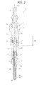
Fig. 2] Fig. 2 is a sectional view showing a configuration of the glow plug. - [
Fig. 3] Fig. 3 is a sectional view of a seal member before the seal member is disposed between a housing and a center pole. - [
Fig. 4] Fig. 4 is a sectional view showing another example of the seal member before the seal member is disposed between the housing and center pole. - [
Fig. 5] Fig. 5 is an enlarged sectional view of the housing and the like, showing configurations of a shoulder portion and the like. - [
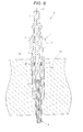
Fig. 6] Fig. 6 is an enlarged sectional view showing the glow plug in a condition mounted in an internal combustion engine. - [
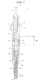
Fig. 7] Fig. 7 is a sectional view showing a protruding portion provided on the center pole, and the like, in another embodiment. - Hereafter, a description will be given, referring to the drawings, of one embodiment.
Fig. 1 is a front view of aglow plug 1, andFig. 2 is a sectional view of theglow plug 1. InFigs. 1 ,2 , and the like, a description will be given with the lower side in the drawings as a leading end side of theglow plug 1 and the upper side as a rear end side. - As shown in
Figs. 1 and2 , theglow plug 1 includes ahousing 2, acenter pole 3, aceramic heater 4 as a heater member, ametal pipe 5, aterminal pin 6, and the like. - The
housing 2 has anaxial hole 7, formed in a cylindrical shape from a predetermined metal material (for example, an iron-based material such as S45C), which extends in a direction of an axis CL1. Furthermore, anexternal thread portion 8 for mounting theglow plug 1 in an internal thread portion provided in a mounting hole of an internal combustion engine is formed on the outer periphery of a central portion of thehousing 2 in the direction of the axis CL1. Besides, atool engagement portion 9 of hexagon cross-section is formed on the outer periphery of a rear end portion of thehousing 2, and an arrangement is such that a mounting tool is engaged with thetool engagement portion 9 when theexternal thread portion 8 is brought into threaded engagement with the internal thread portion. In the embodiment, a configuration is adopted such that a wall thickness of thehousing 2 in the bottom portion of theexternal thread portion 8 is equal to or less than a predetermined value (for example, 1.7mm). - Also, the
metallic center pole 3 of a round bar shape is housed in theaxial hole 7 of thehousing 2. Thecenter pole 3 has a solid core form and, in the embodiment, is configured so as to have a constant outer diameter along the axis CL1. Also, a leading end portion of thecenter pole 3 is joined (for example, welded) to a rear end portion of acylindrical connection member 10 formed from a conductive metal material (for example, an iron-based material such as SUS), and a rear end portion of theceramic heater 4 is press fitted in a leading end portion of theconnection member 10. By so doing, thecenter pole 3 and theceramic heater 4 are mechanically and electrically connected via theconnection member 10. - Furthermore, the metallic
terminal pin 6 is fixed by crimping on a rear end portion of thecenter pole 3, and an insulatingbush 11 formed from an insulating material is provided between a leading end portion of theterminal pin 6 and a rear end portion of thehousing 2 in order to prevent direct conduction (short circuit) between the two. - Besides, the
metal pipe 5 is formed in a cylindrical shape from a predetermined metal material, and joined to the leading end portion of thehousing 2. Also, themetal pipe 5 holds an intermediate portion of theceramic heater 4 in the direction of the axis CL1, and a leading end portion of theceramic heater 4 is in a condition exposed from the leading end of themetal pipe 5. Furthermore, themetal pipe 5 includes on the outer periphery thereof a taperedpress contact portion 5A whose outer diameter decreases gradually toward the leading end side in the direction of the axis CL1. An arrangement is such that when theglow plug 1 is mounted in an internal combustion engine, airtightness in a combustion chamber is secured by thepress contact portion 5A being pressed against a tapered sheet provided in the internal combustion engine. Themetal pipe 5 is joined to thehousing 2 by performing a laser welding along the outer edge of a surface of contact between themetal pipe 5 andhousing 2 in a condition in which a rear end portion of themetal pipe 5 is inserted in theaxial hole 7. - The
ceramic heater 4 includes a round bar-shapedsubstrate 21 extending in the direction of the axis CL1 and an elongatedU-shaped heater element 22 buried inside thesubstrate 21. Thesubstrate 21 is configured from an insulating ceramic (for example, silicon nitride or alumina), and theheater element 22 is configured from a silicon nitride-based conductive ceramic containing a conductive material (for example, carbide or silicide of molybdenum or tungsten). - Also, the
heater element 22 includes aheater portion 23 disposed in a leading end portion of theceramic heater 4 and a pair of bar-shapedlead portions heater portion 23 toward the rear end side. Theheater portion 23 is a region which functions as a so-called heat resistor and has a U-shape so as to follow the curved surface of a leading end portion of theceramic heater 4 formed in a curved surface shape. - Also, the
lead portions ceramic heater 4. Further, an electrode lead-outportion 26 is provided in a position nearer the rear end of onelead portion 24 so as to protrude in an outer peripheral direction, and the electrode lead-outportion 26 is exposed from the outer peripheral surface of theceramic heater 4. In the same way, an electrode lead-outportion 27 is also provided in a position nearer the rear end of theother lead portion 25 so as to protrude in the outer peripheral direction, and the electrode lead-outportion 27 is exposed from the outer peripheral surface of theceramic heater 4. The electrode lead-outportion 26 of the onelead portion 24 is positioned closer to the rear end side in the direction of the axis CL1 than the electrode lead-outportion 27 of theother lead portion 25. - In addition, the exposed portion of the electrode lead-out
portion 26 is in contact with the inner peripheral surface of theconnection member 10, thus achieving an electrical continuity between thecenter pole 3 connected to theconnection member 10 and thelead portion 24. Also, the exposed portion of the electrode lead-outportion 27 is in contact with the inner peripheral surface of themetal pipe 5, thus achieving an electrical continuity between thehousing 2 joined to themetal pipe 5 and thelead portion 25. That is, in the embodiment, an arrangement is such that thecenter pole 3 andhousing 2 function as an anode and cathode for energizing theheater portion 23 of theceramic heater 4. - Furthermore, in order to secure the airtightness in the
axial hole 7, anannular seal member 31 formed from an insulating elastic member (for example, fluororubber or silicone rubber) is provided between thehousing 2 andcenter pole 3. In the embodiment, theseal member 31 is provided between the inner periphery of thehousing 2 and the outer periphery of thecenter pole 3 within a range of formation RA of theexternal thread portion 8 along the axis CL1. Theseal member 31 is provided in theaxial hole 7 by being pushed between thehousing 2 andcenter pole 3 after thehousing 2,center pole 3, and the like have been mounted. - Also, in the embodiment, as shown in
Fig. 3 , on a section of theseal member 31 including a central axis CL2 of theseal member 31 passing through the inner periphery of theseal member 31 before theseal member 31 is disposed between the inner periphery of thehousing 2 and the outer periphery of thecenter pole 3, a first outline OL1, of an outline OL on the section of theseal member 31, positioned on an outer peripheral side (that is, coming into contact with the inner periphery of the housing 2) has a curved shape expanding outward in a radial direction. Meanwhile, a second outline OL2, of the outline OL on the section, positioned on an inner peripheral side (that is, coming into contact with the outer periphery of the center pole 3) has a linear shape along the central axis CL2. - A configuration may be adopted such that the second outline OL2 has a curved shape expanding inward in the radial direction in a condition in which a curvature radius R2 of the second outline OL2 is larger than a curvature radius R1 of the first outline OL1, on the section, as shown in
Fig. 4 . - In addition, as shown in
Fig. 5 , thehousing 2 includes alarge diameter portion 32, with the inner periphery of which theseal member 31 comes into contact, and asmall diameter portion 33, positioned closer to the leading end side in the direction of the axis CL1 than thelarge diameter portion 32, the inner diameter of which is smaller than the inner diameter of thelarge diameter portion 32. In the embodiment, the outer diameter of thelarge diameter portion 32 and the outer diameter of thesmall diameter portion 33 are made substantially equal, and the wall thickness of thesmall diameter portion 33 is larger than the wall thickness of thelarge diameter portion 32. - Also, a
shoulder portion 34, positioned closer to the leading end side in the direction of the axis CL1 than theseal member 31, which protrudes inward in the radial direction is formed at the junction of the leading end of thelarge diameter portion 32 and the rear end of thesmall diameter portion 33. Theshoulder portion 34 is provided within the range of formation RA of theexternal thread portion 8 along the axis CL1 and, in the embodiment, is provided closer to the rear end side in the direction of the axis CL1 by a distance three or more times the thread pitch of theexternal thread portion 8 away from the leading end of the complete thread portion of theexternal thread portion 8. That is, a configuration is adopted such that in a condition in which theglow plug 1 is mounted in an internal combustion engine, the comparatively thin-walledlarge diameter portion 32 is positioned closer to the rear end side than a position to which is applied an axial force in the direction of the axis CL1, and the comparatively thick-walledsmall diameter portion 33 superior in strength is positioned in the position to which the axial force is applied. - Furthermore, in the embodiment, as shown in
Fig. 6 , in a condition in which theexternal thread portion 8 is threadedly engaged with an internal thread portion FS of a mounting hole HO provided in an engine head EH of an internal combustion engine EN, a position in which to dispose theseal member 31 is set so that theseal member 31 is positioned within a range of formation of the internal thread portion FS along the axis CL1. Also, the engine head EH, being cooled by cooling water or the like, is configured in such a way that theexternal thread portion 8 in contact with the engine head EH and the vicinity thereof, of thehousing 2, become a sufficiently low temperature (for example, 100°C or less) even when the internal combustion engine EN is in operation. - In the embodiment, the
glow plug 1 is disposed on the exhaust side of the internal combustion engine EN. Because of this, thetool engagement portion 9 protruding from the engine head EH and the vicinity thereof, of thehousing 2, can become a high temperature of the order of 250°C due to the effect of radiation heat or heat transfer from an exhaust manifold, a turbocharger, or the like. - As heretofore described, according to the embodiment, the
seal member 31 is disposed between thehousing 2 andcenter pole 3 within the range of formation of theexternal thread portion 8 along the axis CL1. Consequently, theseal member 31 is provided in a position spaced apart from thetool engagement portion 9 which can become a high temperature, and it is possible to keep the temperature of theseal member 31 sufficiently low. - Also, as the internal combustion engine EN is cooled by cooling water or the like, the
external thread portion 8 in contact with the internal combustion engine EN (internal thread portion FS) and the vicinity thereof, of thehousing 2, become a sufficiently low temperature (for example, 100°C or less) even in an environment such that thetool engagement portion 9 becomes an extremely high temperature. Because of this, it is possible to keep even lower the temperature of theseal member 31 positioned on the inner side of theexternal thread portion 8. - As above, according to the embodiment, by the heretofore described working effects acting synergistically, it is possible to more reliably prevent a deterioration of the
seal member 31 due to heat. - Furthermore, a configuration is adopted such that the
seal member 31 is positioned on the inner side of theinternal thread portion 8 in a condition in which theexternal thread portion 8 is threadedly engaged with the internal thread portion FS (that is, in a condition in which theglow plug 1 is mounted in the internal combustion engine EN). Consequently, it becomes more difficult for the heat of thetool engagement portion 9 to transfer to theseal member 31, and a region of thehousing 2, whose outer periphery is in contact with the internal thread portion FS (internal combustion engine EN) and which thus becomes a lower temperature, comes into contact with theseal member 31. Because of this, it is possible to keep the temperature of theseal member 31 still lower, and it is possible to more effectively prevent a deterioration of theseal member 31 due to heat. - In addition, it is possible to restrict a movement of the
seal member 31 toward the leading end side beyond theshoulder portion 34 by virtue of theshoulder portion 34 provided on the inner periphery of thehousing 2. Consequently, it is possible to more reliably fulfill the original function of theseal member 31 securing airtightness. - Besides, in the embodiment, the comparatively thin-walled
large diameter portion 32 larger in inner diameter than thesmall diameter portion 33 is provided in a position away from a region to which the axial force can be applied, and the comparatively thick-walledsmall diameter portion 33 smaller in inner diameter than thelarge diameter portion 32 is provided in the position to which the axial force can be applied. Consequently, it is possible to sufficiently secure the mechanical strength of the region of thehousing 2 to which the axial force can be applied. As a result of this, it is possible to more reliably prevent a deformation of thehousing 2. - Also, in the embodiment, a configuration is adopted such that the second outline OL2 of the
seal member 31 has a linear shape or a gently curved shape. Consequently, a region of theseal member 31 configuring the second outline OL2, by supporting the whole of theseal member 31, functions as a center core which prevents theseal member 31 from being distorted or curled, when pushing theseal member 31 between thehousing 2 andcenter pole 3. Consequently, it is possible to more reliably prevent a distortion or wrinkle from occurring on an inner peripheral surface of theseal member 31 coming into contact with thecenter pole 3, and it is possible to more reliably bring the inner peripheral surface of theseal member 31 into contact with thecenter pole 3. As a result of this, it is possible to further enhance the sealing properties between theseal member 31 andcenter pole 3. - Furthermore, the first outline OL1 is formed in a curved shape expanding outward in the radial direction. Because of this, it is possible to smoothly carry out a change in shape of the
seal member 31 by compression. Also, theseal member 31 changes in shape so that a portion large in thickness in the radial direction moves to a portion small in thickness when theseal member 31 changes in shape. Consequently, it is difficult for a deformed region locally high in internal stress to occur in theseal member 31 disposed between thehousing 2 andcenter pole 3. As a result of this, it is possible to more reliably prevent damage to (breakage of) theseal member 31 resulting from internal stress when theglow plug 1 receives a vibration or the like from the exterior. - Also, in the embodiment, as the wall thickness of the
housing 2 in the bottom portion of theexternal thread portion 8 is made equal to or less than the predetermined value, it is possible to increase an amount of heat transferring from theexternal thread portion 8 to the internal combustion engine EN as compared with an amount of heat transferring to theexternal thread portion 8, and theexternal thread portion 8 and the vicinity thereof become a sufficiently low temperature. Consequently, it is possible to still more reliably keep the temperature of theseal member 31 low, and it is possible to effectively prevent a deterioration of theseal member 31 due to heat. Also, as it is possible to achieve a reduction in weight of theglow plug 1 by making the wall thickness of thehousing 2 equal to or less than the predetermined value, it is possible to achieve an improvement in fuel efficiency and a reduction in material cost. - The invention, not being limited to the contents of the description of the heretofore described embodiment, may be implemented in, for example, the following ways. As a matter of course, other applications and modification examples not illustrated hereafter are naturally possible.
-
- (a) In the heretofore described embodiment, the
seal member 31 is disposed closer to the rear end side in the direction of the axis CL1 by a distance three or more times the thread pitch of theexternal thread portion 8 away from the leading end of theexternal thread portion 8 but, a position in which to dispose theseal member 31 not being limited to this, it is sufficient that theseal member 31 is disposed within the range of formation RA of the external thread portion, 8 along the axis CL1. -
- (b) The sectional shape of the
seal member 31 before theseal member 31 is disposed between the inner periphery of thehousing 2 and the outer periphery of thecenter pole 3 is not particularly limited. Consequently, for example, a configuration may be adopted such that the sectional shape of theseal member 31 is circular or rectangular. -
- (c) In the heretofore described embodiment, the
shoulder portion 34 is formed on the inner periphery of thehousing 2 in order to restrict a movement of theseal member 31 toward the leading end side. As opposed to this, a protrudingportion 35, positioned closer to the leading end side in the direction of the axis CL1 than theseal member 31, which protrudes outward in the radial direction may be provided on the outer periphery of thecenter pole 3 within the range of formation of theexternal thread portion 8 along the axis CL1, as shown inFig. 7 . In this case too, it is possible to restrict a movement of theseal member 31 toward the leading end side, in the same way as when theshoulder portion 34 is provided. Also, in this case, the protrudingportion 35 may be provided, closer to the leading end side in the direction of the axis CL1 than the rear end side position, at a distance three times the thread pitch of theexternal thread portion 8 away from the leading end of theexternal thread portion 8. Both theshoulder portion 34 and protrudingportion 35 may be provided, thereby further enhancing the effect of movement restriction of theseal member 31. -
- (d) In the heretofore described embodiment, the technical idea of the invention is applied to the glow plug 1 (a so-called ceramic glow plug) having the
ceramic heater 4 acting as a heater member. However, a glow plug to which the technical idea of the invention can be applied is not limited to this. Consequently, the technical idea of the invention may be applied to, for example, a glow plug (a so-called metal glow plug) including as a heater member a sheathed heater configured having a heater coil formed from a conductive metal. -
- (e) In the heretofore described embodiment, the
glow plug 1 is disposed on the exhaust side of the internal combustion engine EN, but theglow plug 1 may be disposed on the intake side of the internal combustion engine EN. That is, a position in the internal combustion engine EN in which to dispose theglow plug 1 is not particularly limited. -
- (f) In the heretofore described embodiment, the
center pole 3 is configured so as to have an outer diameter constant along the axis CL1, but a taper wherein the outer diameter of thecenter pole 3 is gradually reduced toward the leading end side may be provided on the leading end side of thecenter pole 3. In this case, it is possible to achieve, for example, a relaxation of stress transferring from thecenter pole 3 to theceramic heater 4. It is preferable that the taper is provided closer to the leading end side than theshoulder portion 34 and protrudingportion 35. -
- (g) In the heretofore described embodiment, the
center pole 3 and theceramic heater 4 are electrically connected via theconnection member 10, but thecenter pole 3 and theceramic heater 4 may be electrically connected by a predetermined lead wire or the like. -
- (h) The shape of the
ceramic heater 4, not being particularly limited, may be, for example, elliptical in section, rectangular in section, or polygonal in section. Also, a so-called plate-like heater wherein a heater element is sandwiched between a plurality of substrates formed plate-like may be used as a ceramic heater. - 1 ··· Glow plug, 2 ··· Housing, 3 ··· Center pole, 4 ··· Ceramic heater (heater member), 7 ··· Axial hole, 8 ··· External thread portion, 9 ··· Tool engagement portion, 31 ··· Seal member, 32 ··· Large diameter portion, 33 ··· Small diameter portion, 34 ··· Shoulder portion, 35 ··· Protruding portion, CL1 ··· Axis, CL2 ··· Central axis (of seal member), EN ··· Internal combustion engine, FS ··· Internal thread portion, HO ··· Mounting hole, OL ··· Outline, OL1 ··· First outline, OL2 ··· Second outline.
Claims (6)
- A glow plug (1), characterized by comprising:a cylindrical housing (2), having an axial hole (7) extending in a direction of an axis (CL1), which includes an external thread portion (8) for coming into threaded engagement with an internal thread portion (FS) provided on a mounting hole (HO) of an internal combustion engine (EN), and a tool engagement portion (9), positioned closer to a rear end side than the external thread portion (8), with which a tool is engaged when mounting the glow plug (1) in the internal combustion engine (EN);a heater member (4) inserted in the axial hole (7) in a condition in which at least a leading end portion of the heater member (4) protrudes from the leading end of the housing (2); anda center pole (3), having a bar shape extending in the direction of the axis (CL1) and inserted into the axial hole (7), which forms an energizing path to the heater member (4), whereinan annular seal member (31) formed from an insulating material is disposed between the inner periphery of the housing (2) and the outer periphery of the center pole (3) within a range of formation of the external thread portion (8) along the axis (CL1).
- The glow plug (1) according to claim 1, characterized in that
in a condition in which the external thread portion (8) is threadedly engaged with the internal thread portion (FS), the seal member (31) is positioned within a range of formation of the internal thread portion (FS) along the axis (CL1). - The glow plug (1) according to claim 1 or 2, characterized in that
a shoulder portion (34), positioned closer to a leading end side in the direction of the axis (CL1) than the seal member (31), which protrudes inward in a radial direction is provided on the inner periphery of the housing (2) within the range of formation of the external thread portion (8) along the axis (CL1). - The glow plug (1) according to claim 3, characterized in that
the housing (2) includes:a large diameter portion (32) with the inner periphery of which the seal member (31) comes into contact; anda small diameter portion (33), positioned closer to the leading end side in the direction of the axis (CL1) than the large diameter portion (32), whose inner diameter is smaller than the inner diameter of the large diameter portion (32), whereinthe shoulder portion (34) is configured of a region linking the leading end of the large diameter portion (32) and the rear end of the small diameter portion (33), andthe shoulder portion (34) is provided closer to the rear end side in the direction of the axis (CL1) by a distance three or more times the thread pitch of the external thread portion (8) away from the leading end of the complete thread portion of the external thread portion (8). - The glow plug (1) according to any one of claims 1 to 4, characterized in that
a protruding portion (35), positioned closer to the leading end side in the direction of the axis (CL1) than the seal member (31), which protrudes outward in the radial direction is provided on the outer periphery of the center pole (3) within the range of formation of the external thread portion (8) along the axis (CL1). - The glow plug (1) according to any one of claims 1 to 5, characterized in that
the seal member (31) is formed from an insulating elastic material, and
on a section of the seal member (31) including a central axis (CL2) of the seal member (31) before the seal member (31) is disposed between the inner periphery of the housing (2) and the outer periphery of the center pole (3),
an outline (OL) on the section of the seal member (31) has:a first outline (OL1), positioned on the outer peripheral side, which has a curved shape expanding outward in the radial direction; anda second outline (OL2), positioned on the inner peripheral side, which has a curved shape expanding inward in the radial direction in a condition in which the radius curvature of the second outline (OL2) is larger than the radius curvature of the first outline (OL1), or a linear shape along the central axis (CL2) of the seal member (31).
Applications Claiming Priority (1)
| Application Number | Priority Date | Filing Date | Title |
|---|---|---|---|
| JP2012035757A JP5922946B2 (en) | 2012-02-22 | 2012-02-22 | Glow plug |
Publications (2)
| Publication Number | Publication Date |
|---|---|
| EP2631542A2 true EP2631542A2 (en) | 2013-08-28 |
| EP2631542A3 EP2631542A3 (en) | 2017-12-20 |
Family
ID=48143429
Family Applications (1)
| Application Number | Title | Priority Date | Filing Date |
|---|---|---|---|
| EP13156421.3A Withdrawn EP2631542A3 (en) | 2012-02-22 | 2013-02-22 | Glow plug |
Country Status (3)
| Country | Link |
|---|---|
| EP (1) | EP2631542A3 (en) |
| JP (1) | JP5922946B2 (en) |
| KR (1) | KR101586878B1 (en) |
Families Citing this family (1)
| Publication number | Priority date | Publication date | Assignee | Title |
|---|---|---|---|---|
| JP6251578B2 (en) * | 2014-01-20 | 2017-12-20 | 日本特殊陶業株式会社 | Glow plug |
Citations (1)
| Publication number | Priority date | Publication date | Assignee | Title |
|---|---|---|---|---|
| JP2005315474A (en) | 2004-04-27 | 2005-11-10 | Ngk Spark Plug Co Ltd | Glow plug |
Family Cites Families (16)
| Publication number | Priority date | Publication date | Assignee | Title |
|---|---|---|---|---|
| JPS4534016Y1 (en) * | 1968-03-30 | 1970-12-25 | ||
| DE2900984C2 (en) * | 1979-01-12 | 1983-01-05 | W.C. Heraeus Gmbh, 6450 Hanau | Glow plug for diesel engines |
| GB2224074B (en) * | 1988-10-19 | 1992-12-09 | Wellman Automotive Products Li | Glow plug |
| JPH0484863U (en) * | 1990-11-29 | 1992-07-23 | ||
| JP4128295B2 (en) * | 1999-02-04 | 2008-07-30 | 日本特殊陶業株式会社 | Glow plug |
| JP3911930B2 (en) * | 1999-10-28 | 2007-05-09 | 株式会社デンソー | Glow plug with combustion pressure sensor |
| JP3823003B2 (en) * | 2000-02-28 | 2006-09-20 | 日本特殊陶業株式会社 | Seeds type glow plug and manufacturing method thereof |
| JP3900060B2 (en) * | 2002-10-07 | 2007-04-04 | 株式会社デンソー | Glow plug with combustion pressure sensor |
| JP2004263951A (en) * | 2003-03-03 | 2004-09-24 | Ngk Spark Plug Co Ltd | Glow plug |
| DE102004024341B3 (en) * | 2004-05-17 | 2005-12-22 | Beru Ag | pressure measuring glow |
| JP2006112478A (en) * | 2004-10-13 | 2006-04-27 | Nok Corp | Reciprocal sealing ring |
| JP2007032877A (en) * | 2005-07-22 | 2007-02-08 | Ngk Spark Plug Co Ltd | Glow plug and manufacturing method thereof |
| JP4960118B2 (en) * | 2006-03-30 | 2012-06-27 | 日本特殊陶業株式会社 | Glow plug |
| EP2136142A1 (en) * | 2007-03-12 | 2009-12-23 | NGK Spark Plug Co., Ltd. | Method for manufacturing glow plug and glow plug |
| DE102008008205A1 (en) * | 2008-02-07 | 2009-08-13 | Robert Bosch Gmbh | Metallic glow plug with temperature measurement |
| JP5296489B2 (en) * | 2008-10-17 | 2013-09-25 | 日本特殊陶業株式会社 | Glow plug and method of manufacturing the glow plug |
-
2012
- 2012-02-22 JP JP2012035757A patent/JP5922946B2/en active Active
-
2013
- 2013-02-21 KR KR1020130018510A patent/KR101586878B1/en not_active Expired - Fee Related
- 2013-02-22 EP EP13156421.3A patent/EP2631542A3/en not_active Withdrawn
Patent Citations (1)
| Publication number | Priority date | Publication date | Assignee | Title |
|---|---|---|---|---|
| JP2005315474A (en) | 2004-04-27 | 2005-11-10 | Ngk Spark Plug Co Ltd | Glow plug |
Also Published As
| Publication number | Publication date |
|---|---|
| JP5922946B2 (en) | 2016-05-24 |
| JP2013170774A (en) | 2013-09-02 |
| KR20130096667A (en) | 2013-08-30 |
| KR101586878B1 (en) | 2016-01-19 |
| EP2631542A3 (en) | 2017-12-20 |
Similar Documents
| Publication | Publication Date | Title |
|---|---|---|
| US9088136B2 (en) | Corona ignition device with improved electrical performance | |
| EP2541702A1 (en) | Plug cap | |
| EP2662623B1 (en) | Glow plug and manufacturing method thereof | |
| CN103608977A (en) | Pin terminal | |
| EP2679905B1 (en) | Glow plug with pressure sensor | |
| US11916357B2 (en) | Spark plug with mechanically and thermally coupled center electrode | |
| JP5525106B2 (en) | Ceramic glow plug | |
| JP6405039B2 (en) | Glow pin plug | |
| JP5485843B2 (en) | Glow plug and manufacturing method thereof | |
| CN106716753B (en) | Insulator and spark plug | |
| EP3045817A1 (en) | Glow plug with combustion pressure sensor | |
| KR101586878B1 (en) | Glow plug | |
| EP2669578B1 (en) | Glow plug | |
| JP2016522386A (en) | Sheath type glow plug with heating element made of inner contact type ceramic and method for manufacturing the same | |
| US20200412104A1 (en) | Spark plug | |
| US8222803B2 (en) | Spark plug and manufacturing method thereof | |
| US10253982B2 (en) | Glow plug with pressure sensor | |
| JP5207309B2 (en) | Spark plug | |
| JP6059503B2 (en) | Ceramic glow plug with pressure sensor | |
| US20190296525A1 (en) | Spark plug | |
| KR20140139524A (en) | Glow plug and method for manufacturing same | |
| EP3285004A1 (en) | Glow plug | |
| EP3287699A1 (en) | Glow plug | |
| JP2021025755A (en) | heater | |
| JP2015135224A (en) | glow plug |
Legal Events
| Date | Code | Title | Description |
|---|---|---|---|
| PUAI | Public reference made under article 153(3) epc to a published international application that has entered the european phase |
Free format text: ORIGINAL CODE: 0009012 |
|
| AK | Designated contracting states |
Kind code of ref document: A2 Designated state(s): AL AT BE BG CH CY CZ DE DK EE ES FI FR GB GR HR HU IE IS IT LI LT LU LV MC MK MT NL NO PL PT RO RS SE SI SK SM TR |
|
| AX | Request for extension of the european patent |
Extension state: BA ME |
|
| PUAL | Search report despatched |
Free format text: ORIGINAL CODE: 0009013 |
|
| RIC1 | Information provided on ipc code assigned before grant |
Ipc: F23Q 7/00 20060101AFI20171109BHEP |
|
| AK | Designated contracting states |
Kind code of ref document: A3 Designated state(s): AL AT BE BG CH CY CZ DE DK EE ES FI FR GB GR HR HU IE IS IT LI LT LU LV MC MK MT NL NO PL PT RO RS SE SI SK SM TR |
|
| AX | Request for extension of the european patent |
Extension state: BA ME |
|
| STAA | Information on the status of an ep patent application or granted ep patent |
Free format text: STATUS: THE APPLICATION IS DEEMED TO BE WITHDRAWN |
|
| 18D | Application deemed to be withdrawn |
Effective date: 20180621 |