EP2631458A1 - Engine control method - Google Patents
Engine control method Download PDFInfo
- Publication number
- EP2631458A1 EP2631458A1 EP11834425.8A EP11834425A EP2631458A1 EP 2631458 A1 EP2631458 A1 EP 2631458A1 EP 11834425 A EP11834425 A EP 11834425A EP 2631458 A1 EP2631458 A1 EP 2631458A1
- Authority
- EP
- European Patent Office
- Prior art keywords
- output
- value
- fuel
- flow rate
- actual value
- Prior art date
- Legal status (The legal status is an assumption and is not a legal conclusion. Google has not performed a legal analysis and makes no representation as to the accuracy of the status listed.)
- Granted
Links
- 238000000034 method Methods 0.000 title claims abstract description 25
- 239000000446 fuel Substances 0.000 claims abstract description 380
- 239000007789 gas Substances 0.000 claims abstract description 86
- 239000000203 mixture Substances 0.000 claims abstract description 53
- QVGXLLKOCUKJST-UHFFFAOYSA-N atomic oxygen Chemical compound [O] QVGXLLKOCUKJST-UHFFFAOYSA-N 0.000 claims abstract description 19
- 239000001301 oxygen Substances 0.000 claims abstract description 19
- 229910052760 oxygen Inorganic materials 0.000 claims abstract description 19
- 238000002347 injection Methods 0.000 claims description 13
- 239000007924 injection Substances 0.000 claims description 13
- 230000003247 decreasing effect Effects 0.000 claims description 5
- 230000004044 response Effects 0.000 description 19
- 230000002123 temporal effect Effects 0.000 description 19
- 239000002737 fuel gas Substances 0.000 description 16
- 238000002309 gasification Methods 0.000 description 15
- 230000007423 decrease Effects 0.000 description 14
- 230000002093 peripheral effect Effects 0.000 description 11
- 238000010248 power generation Methods 0.000 description 9
- 238000002485 combustion reaction Methods 0.000 description 5
- 238000000197 pyrolysis Methods 0.000 description 5
- 230000037361 pathway Effects 0.000 description 4
- 239000002028 Biomass Substances 0.000 description 3
- 230000000694 effects Effects 0.000 description 3
- 239000002916 wood waste Substances 0.000 description 2
- 239000002551 biofuel Substances 0.000 description 1
- 230000029142 excretion Effects 0.000 description 1
- 230000004048 modification Effects 0.000 description 1
- 238000012986 modification Methods 0.000 description 1
- 239000002994 raw material Substances 0.000 description 1
- 239000000243 solution Substances 0.000 description 1
- 239000002699 waste material Substances 0.000 description 1
Images







Classifications
-
- F—MECHANICAL ENGINEERING; LIGHTING; HEATING; WEAPONS; BLASTING
- F02—COMBUSTION ENGINES; HOT-GAS OR COMBUSTION-PRODUCT ENGINE PLANTS
- F02D—CONTROLLING COMBUSTION ENGINES
- F02D11/00—Arrangements for, or adaptations to, non-automatic engine control initiation means, e.g. operator initiated
- F02D11/06—Arrangements for, or adaptations to, non-automatic engine control initiation means, e.g. operator initiated characterised by non-mechanical control linkages, e.g. fluid control linkages or by control linkages with power drive or assistance
- F02D11/10—Arrangements for, or adaptations to, non-automatic engine control initiation means, e.g. operator initiated characterised by non-mechanical control linkages, e.g. fluid control linkages or by control linkages with power drive or assistance of the electric type
-
- F—MECHANICAL ENGINEERING; LIGHTING; HEATING; WEAPONS; BLASTING
- F02—COMBUSTION ENGINES; HOT-GAS OR COMBUSTION-PRODUCT ENGINE PLANTS
- F02D—CONTROLLING COMBUSTION ENGINES
- F02D19/00—Controlling engines characterised by their use of non-liquid fuels, pluralities of fuels, or non-fuel substances added to the combustible mixtures
- F02D19/02—Controlling engines characterised by their use of non-liquid fuels, pluralities of fuels, or non-fuel substances added to the combustible mixtures peculiar to engines working with gaseous fuels
- F02D19/021—Control of components of the fuel supply system
- F02D19/023—Control of components of the fuel supply system to adjust the fuel mass or volume flow
-
- F—MECHANICAL ENGINEERING; LIGHTING; HEATING; WEAPONS; BLASTING
- F02—COMBUSTION ENGINES; HOT-GAS OR COMBUSTION-PRODUCT ENGINE PLANTS
- F02D—CONTROLLING COMBUSTION ENGINES
- F02D19/00—Controlling engines characterised by their use of non-liquid fuels, pluralities of fuels, or non-fuel substances added to the combustible mixtures
- F02D19/02—Controlling engines characterised by their use of non-liquid fuels, pluralities of fuels, or non-fuel substances added to the combustible mixtures peculiar to engines working with gaseous fuels
- F02D19/026—Measuring or estimating parameters related to the fuel supply system
- F02D19/029—Determining density, viscosity, concentration or composition
-
- F—MECHANICAL ENGINEERING; LIGHTING; HEATING; WEAPONS; BLASTING
- F02—COMBUSTION ENGINES; HOT-GAS OR COMBUSTION-PRODUCT ENGINE PLANTS
- F02D—CONTROLLING COMBUSTION ENGINES
- F02D29/00—Controlling engines, such controlling being peculiar to the devices driven thereby, the devices being other than parts or accessories essential to engine operation, e.g. controlling of engines by signals external thereto
- F02D29/06—Controlling engines, such controlling being peculiar to the devices driven thereby, the devices being other than parts or accessories essential to engine operation, e.g. controlling of engines by signals external thereto peculiar to engines driving electric generators
-
- F—MECHANICAL ENGINEERING; LIGHTING; HEATING; WEAPONS; BLASTING
- F02—COMBUSTION ENGINES; HOT-GAS OR COMBUSTION-PRODUCT ENGINE PLANTS
- F02D—CONTROLLING COMBUSTION ENGINES
- F02D41/00—Electrical control of supply of combustible mixture or its constituents
- F02D41/0002—Controlling intake air
-
- F—MECHANICAL ENGINEERING; LIGHTING; HEATING; WEAPONS; BLASTING
- F02—COMBUSTION ENGINES; HOT-GAS OR COMBUSTION-PRODUCT ENGINE PLANTS
- F02D—CONTROLLING COMBUSTION ENGINES
- F02D41/00—Electrical control of supply of combustible mixture or its constituents
- F02D41/0025—Controlling engines characterised by use of non-liquid fuels, pluralities of fuels, or non-fuel substances added to the combustible mixtures
- F02D41/0027—Controlling engines characterised by use of non-liquid fuels, pluralities of fuels, or non-fuel substances added to the combustible mixtures the fuel being gaseous
-
- F—MECHANICAL ENGINEERING; LIGHTING; HEATING; WEAPONS; BLASTING
- F02—COMBUSTION ENGINES; HOT-GAS OR COMBUSTION-PRODUCT ENGINE PLANTS
- F02D—CONTROLLING COMBUSTION ENGINES
- F02D41/00—Electrical control of supply of combustible mixture or its constituents
- F02D41/02—Circuit arrangements for generating control signals
- F02D41/021—Introducing corrections for particular conditions exterior to the engine
-
- F—MECHANICAL ENGINEERING; LIGHTING; HEATING; WEAPONS; BLASTING
- F02—COMBUSTION ENGINES; HOT-GAS OR COMBUSTION-PRODUCT ENGINE PLANTS
- F02D—CONTROLLING COMBUSTION ENGINES
- F02D41/00—Electrical control of supply of combustible mixture or its constituents
- F02D41/02—Circuit arrangements for generating control signals
- F02D41/14—Introducing closed-loop corrections
- F02D41/1438—Introducing closed-loop corrections using means for determining characteristics of the combustion gases; Sensors therefor
- F02D41/1444—Introducing closed-loop corrections using means for determining characteristics of the combustion gases; Sensors therefor characterised by the characteristics of the combustion gases
- F02D41/1454—Introducing closed-loop corrections using means for determining characteristics of the combustion gases; Sensors therefor characterised by the characteristics of the combustion gases the characteristics being an oxygen content or concentration or the air-fuel ratio
-
- F—MECHANICAL ENGINEERING; LIGHTING; HEATING; WEAPONS; BLASTING
- F02—COMBUSTION ENGINES; HOT-GAS OR COMBUSTION-PRODUCT ENGINE PLANTS
- F02D—CONTROLLING COMBUSTION ENGINES
- F02D9/00—Controlling engines by throttling air or fuel-and-air induction conduits or exhaust conduits
- F02D9/02—Controlling engines by throttling air or fuel-and-air induction conduits or exhaust conduits concerning induction conduits
-
- F—MECHANICAL ENGINEERING; LIGHTING; HEATING; WEAPONS; BLASTING
- F02—COMBUSTION ENGINES; HOT-GAS OR COMBUSTION-PRODUCT ENGINE PLANTS
- F02M—SUPPLYING COMBUSTION ENGINES IN GENERAL WITH COMBUSTIBLE MIXTURES OR CONSTITUENTS THEREOF
- F02M21/00—Apparatus for supplying engines with non-liquid fuels, e.g. gaseous fuels stored in liquid form
- F02M21/02—Apparatus for supplying engines with non-liquid fuels, e.g. gaseous fuels stored in liquid form for gaseous fuels
- F02M21/0203—Apparatus for supplying engines with non-liquid fuels, e.g. gaseous fuels stored in liquid form for gaseous fuels characterised by the type of gaseous fuel
- F02M21/0215—Mixtures of gaseous fuels; Natural gas; Biogas; Mine gas; Landfill gas
-
- F—MECHANICAL ENGINEERING; LIGHTING; HEATING; WEAPONS; BLASTING
- F02—COMBUSTION ENGINES; HOT-GAS OR COMBUSTION-PRODUCT ENGINE PLANTS
- F02D—CONTROLLING COMBUSTION ENGINES
- F02D2200/00—Input parameters for engine control
- F02D2200/02—Input parameters for engine control the parameters being related to the engine
- F02D2200/04—Engine intake system parameters
- F02D2200/0404—Throttle position
-
- F—MECHANICAL ENGINEERING; LIGHTING; HEATING; WEAPONS; BLASTING
- F02—COMBUSTION ENGINES; HOT-GAS OR COMBUSTION-PRODUCT ENGINE PLANTS
- F02D—CONTROLLING COMBUSTION ENGINES
- F02D2200/00—Input parameters for engine control
- F02D2200/02—Input parameters for engine control the parameters being related to the engine
- F02D2200/06—Fuel or fuel supply system parameters
- F02D2200/0611—Fuel type, fuel composition or fuel quality
-
- F—MECHANICAL ENGINEERING; LIGHTING; HEATING; WEAPONS; BLASTING
- F02—COMBUSTION ENGINES; HOT-GAS OR COMBUSTION-PRODUCT ENGINE PLANTS
- F02D—CONTROLLING COMBUSTION ENGINES
- F02D2250/00—Engine control related to specific problems or objectives
- F02D2250/18—Control of the engine output torque
- F02D2250/26—Control of the engine output torque by applying a torque limit
-
- F—MECHANICAL ENGINEERING; LIGHTING; HEATING; WEAPONS; BLASTING
- F02—COMBUSTION ENGINES; HOT-GAS OR COMBUSTION-PRODUCT ENGINE PLANTS
- F02M—SUPPLYING COMBUSTION ENGINES IN GENERAL WITH COMBUSTIBLE MIXTURES OR CONSTITUENTS THEREOF
- F02M21/00—Apparatus for supplying engines with non-liquid fuels, e.g. gaseous fuels stored in liquid form
- F02M21/02—Apparatus for supplying engines with non-liquid fuels, e.g. gaseous fuels stored in liquid form for gaseous fuels
- F02M21/04—Gas-air mixing apparatus
- F02M21/047—Venturi mixer
-
- Y—GENERAL TAGGING OF NEW TECHNOLOGICAL DEVELOPMENTS; GENERAL TAGGING OF CROSS-SECTIONAL TECHNOLOGIES SPANNING OVER SEVERAL SECTIONS OF THE IPC; TECHNICAL SUBJECTS COVERED BY FORMER USPC CROSS-REFERENCE ART COLLECTIONS [XRACs] AND DIGESTS
- Y02—TECHNOLOGIES OR APPLICATIONS FOR MITIGATION OR ADAPTATION AGAINST CLIMATE CHANGE
- Y02T—CLIMATE CHANGE MITIGATION TECHNOLOGIES RELATED TO TRANSPORTATION
- Y02T10/00—Road transport of goods or passengers
- Y02T10/10—Internal combustion engine [ICE] based vehicles
- Y02T10/30—Use of alternative fuels, e.g. biofuels
-
- Y—GENERAL TAGGING OF NEW TECHNOLOGICAL DEVELOPMENTS; GENERAL TAGGING OF CROSS-SECTIONAL TECHNOLOGIES SPANNING OVER SEVERAL SECTIONS OF THE IPC; TECHNICAL SUBJECTS COVERED BY FORMER USPC CROSS-REFERENCE ART COLLECTIONS [XRACs] AND DIGESTS
- Y02—TECHNOLOGIES OR APPLICATIONS FOR MITIGATION OR ADAPTATION AGAINST CLIMATE CHANGE
- Y02T—CLIMATE CHANGE MITIGATION TECHNOLOGIES RELATED TO TRANSPORTATION
- Y02T10/00—Road transport of goods or passengers
- Y02T10/10—Internal combustion engine [ICE] based vehicles
- Y02T10/40—Engine management systems
Definitions
- the current invention relates to an engine control method for controlling the engine, when a calorific value per unit volume of fuel changes.
- Fuel is usually constituted by a large number of components which are different in composition, and the each component has a different calorific value. Therefore, the calorific value of the fuel itself changes with the concentration of the each component. For example, in the case of fuel generated at a gasification furnace, the concentration of a component is greatly affected according to the kind of raw material of gas, and the operational status of the gasification furnace. Therefore, with the fuel generated at the gasification furnace, the calorific value of fuel per unit volume changes in time.
- fuel generated at a gasification furnace there are fuel gas acquired by carrying out pyrolysis of wood waste and so on, fuel gas discharged from a waste disposal plant, biofuel gas acquired from biotic excretion and so on, and natural flow fuel gas from reclaimed land and so on.
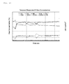
- Fig. 18 is a view showing temporal responses of concentration of each component and lower calorific value (LHV) of the fuel itself, about fuel supplied from a gasification furnace.
- the concentration of each component is changing in time.
- the calorific value the calorific value per unit volume of the fuel itself is also changing in time.
- the patent document 1 discloses a biomass gasification system which uses pyrolysis gas generated by carrying out the pyrolysis of biomass feedstock, as fuel gas.
- the pyrolysis gas generated from the biomass feedstock is also fuel where the concentration of the component changes in time.
- Fig. 19 is a view showing temporal responses of a generated gas volume (a), a gas calorific value (b), a possible generator output (c), and a throttle aperture (d).
- Fig. 19 (a) shows a temporal response of a generated gas volume At of fuel gas generated from a gasification furnace.
- the generated gas volume At is constant in general with time, because the generated gas volume At cannot be changed greatly on the composition of a gasification furnace.
- the engine uses the fuel gas generated from the gasification furnace as fuel. The fuel gas which has not been used for combustion with the engine is discarded as it is.
- Fig. 19 (b) shows a temporal response of a calorific value H of fuel gas.
- the calorific value H of fuel gas changes in time, because the component of fuel generated from a gasification furnace changes in time. Therefore, a theoretical air-fuel ratio changes in time.
- Fig. 19 (c) shows a temporal response of a possible generator output PM in case that fuel gas from a gasification furnace is used to the maximum.
- the engine is used as a source of a drive source of a generator, and the generator output of the generator is proportional to an engine output.
- the possible generator output PM fundamentally changes in proportion to the calorific value.
- the possible generator output PM is restricted by a maximum fuel flow rate and a maximum air flow rate.
- the maximum fuel flow rate is equal to the generated gas volume At.
- the maximum air flow rate is an air flow rate when the throttle aperture is maintained at the maximum, for example. Since the generated gas volume At is approximately a constant value in Fig. 19 (a) , the possible generator output PM is restricted by a limit value TL of the throttle aperture. The throttle aperture limit value TL is shown in Fig. 19 (d) . Moreover, the possible generator output PM is restricted also by a generator output upper limit value PG. The generator output upper limit value PG shows an output limit of the generator.
- the possible generator output PM As an actual output, according to change of the calorific value, it is necessary to set the possible generator output PM as a target value of the generator output. For example, when the target value of the generator output is set more highly than the possible generator output PM, the actual value of the generator output cannot reach the target value by shortage of the fuel flow rate or shortage of the air flow rate. That is, output control falls into impossible status. As a case of loss of output control, even if the throttle aperture is maintained at the maximum, specifically, there is a case that the air flow rate may be insufficient, for example.
- the target value of the generator output is maintained at an output limit value PL of a constant value.
- the output limit value PL is a value of the power generation electric power which can be output, when the throttle aperture is at the maximum, in the calorific value of the minimum value assumed.
- Fig. 19 (d) shows a temporal response of an actual value TR of a throttle aperture in case that a target value of a generator output is maintained at output limit value PL.
- the actual value TR of the throttle aperture is changed so that the actual value of the generator output may be maintained at the output limit value PL.
- change of the actual value TR of the throttle aperture is in inverse proportion to change of the calorific value.
- a use gas volume Ap is proportional to change of the actual value TR of the throttle aperture.
- the use gas volume Ap shows a gas volume used for power generation
- an abandonment gas volume Ad shows a gas volume thrown away vainly.
- the generated gas volume At is equal to a sum total of the use gas volume Ap and the abandonment gas volume Ad.
- Patent documents 1 1
- the target value of the generator output is maintained at the constant value set according to the minimum value of the calorific value. That is, the target value of the generator output is set according to the minimum value of a possible generator output. Since the amount of use of fuel gas is set according to the case where the calorific value is low, the amount of use of fuel gas falls, when the calorific value is high. As a result, as shown in Fig. 19 (a) , a ratio of the abandonment gas volume Ad to the generated gas volume At becomes comparatively large.
- the current invention provides an engine control method which can heighten an output as much as possible according to change of calorific value, while preventing the occurrence of loss of output control.
- the current invention provides an engine control method for controlling an engine when a calorific value per unit volume of fuel changes, the engine control method comprising the steps of: detecting an actual value of oxygen concentration in exhaust gas; detecting an actual value of a fuel flow rate and an actual value of an air flow rate; detecting an actual value of a theoretical air-fuel ratio changing according to the calorific value, based on the actual value of the oxygen concentration, the actual value of the fuel flow rate, and the actual value of the air flow rate; controlling a first controlled variable determining the air-fuel ratio so that the actual value of the air-fuel ratio coincides with the actual value of the theoretical air-fuel ratio; setting a target value of an output of the engine to an output limit value; detecting an actual value of the output; and controlling a second controlled variable determining the air flow rate or a mixture gas flow rate so that the actual value of the output coincides with the target value of the output, wherein the output limit value is a size of the output acquired when the air-fuel ratio is maintained at the theoretical air-fuel ratio and the
- the output limit value corresponding to the actual value of the output and the actual value of the second controlled variable is specified, based on correlation among the output, the second controlled variable, and the output limit value, and the output limit value is set to the target value of the output.
- the target value of the output is set to the output limit value, by changing or maintaining the target value of the output so that the actual value of the second controlled variable is maintained at the second limit value.
- the engine control method comprises the steps of: setting an output upper limit value; and coinciding the target value of the output with the output upper limit value when the target value of the output is higher than the output upper limit value.
- the engine control method comprises the steps of: setting a fuel flow rate limit value; and coinciding the actual value of the fuel flow rate with the fuel flow rate limit value by decreasing the target value of the output, when the actual value of the fuel flow rate is higher than the fuel flow rate limit value.
- the first controlled variable is an aperture of a fuel control valve for controlling a flow rate of the fuel supplied to a mixer.
- the second controlled variable is an aperture of a throttle valve.
- the second controlled variable is air supply pressure.
- a controlled variable for specifying the fuel flow rate is an aperture of a fuel control valve for controlling a flow rate of the fuel supplied to a mixer; and a throttle aperture, air supply pressure and air supply temperature, or air supply pressure.
- a controlled variable for specifying the fuel flow rate is a pressure differential of fuel pressure between upper stream side and lower stream side of a fuel control valve for controlling a flow rate of the fuel supplied to a mixer; and a throttle aperture, air supply pressure and air supply temperature, or air supply pressure.
- the target value of the output changes according to change of the calorific value. Since the target value of the output is set so that the actual value of the second controlled variable is maintained at a predetermined limit value, the occurrence of loss of output control is prevented. Therefore, the engine control method according to the current invention can heighten the output as much as possible according to change of the calorific value, while preventing the occurrence of loss of output control.
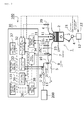
- Fig. 1 is a schematic view showing an engine, an engine control system, and a fuel source (Example 1).
- Fig. 2 is a flow chart of output control (Example 1).
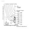
- Fig. 3 is a view showing correlation of an output, a throttle aperture, and power generation output limit value, in the status that an air-fuel ratio is maintained at a theoretical air-fuel ratio (Example 1).
- Fig. 4 is a view showing correlation of Fig. 3 and change of operational status (Example 1).
- Fig. 5 is a view showing temporal responses of a gas calorific value (a), an actual power generation output (b), a power generation output limit value (c), and a throttle aperture (d) (Example 1).
- Fig. 6 is a schematic view showing an engine, an engine control system, and a fuel source (Example 2).
- Fig. 7 is a flow chart of output control (Example 2).
- Fig. 8 is a flow chart of output control (Example 3).
- Fig. 9 is a schematic view showing an engine, an engine control system, and a fuel source (Example 4).
- Fig. 10 is a flow chart of output control (Example 4).
- Fig. 11 is a flow chart of output control (Example 5).
- Fig. 12 is a schematic view showing an engine, an engine control system, and a fuel source (Example 6).
- Fig. 13 is a flow chart of output control (Example 6).
- Fig. 14 is a schematic view showing an engine, an engine control system, and a fuel source (Example 7).
- Fig. 15 is a flow chart of output control (Example 7).
- Fig. 16 is a schematic view showing an engine, an engine control system, and a fuel source (Example 8).
- Fig. 17 is a flow chart of output control (Example 8).
- Fig. 18 is a view showing temporal responses of concentration of each component and lower calorific value (LHV) of fuel, about the fuel supplied from a gasification furnace.
- LHV lower calorific value
- Fig. 19 is a view showing temporal responses of a generated gas volume (a), a gas calorific value (b), a possible generator output (c), and a throttle aperture (d).
- Fig. 1 is a schematic view showing an engine 1, an engine control system 100, and a fuel source 200 (Example 1).
- the engine 1 has a cylinder 2, a piston 3, a crankshaft 4, an air supply pipe 5, an exhaust pipe 6, a throttle valve 7, a Venturi style mixer 8, a fuel control valve 9, a fuel piping 10, a spark plug 11, and a gas pressure regulator 13.
- the engine 1 is a premixed-gas-combustion engine which has a fuel control valve and a mixer.
- the throttle valve 7 and the Venturi style mixer 8 are arranged in the air supply pipe 5.
- the throttle valve 7 is in the lower stream side of the Venturi style mixer 8 in an air supply direction.
- the fuel piping 10 supplies fuel to the Venturi style mixer 8 from the fuel source 200.
- the fuel control valve 9 is arranged on the pathway of the fuel piping 10.
- the gas pressure regulator 13 controls pressure of the fuel supplied to the Venturi style mixer 8.
- the gas pressure regulator 13 is arranged at the upper stream side of the fuel control valve 9, on the pathway of the fuel piping 10.
- the crankshaft 4 is connected to the generator 12.
- the fuel source 200 supplies the fuel where a calorific value per unit volume changes in time, to the engine 1.
- the fuel source 200 is a gasification furnace which generates fuel gas by carrying out pyrolysis of wood waste, for example.
- the engine control system 100 has an engine speed sensor 21, an output sensor 22, an air supply pressure sensor 23, an air supply temperature sensor 24, a throttle aperture sensor 25, a fuel control valve aperture sensor 26, an oxygen sensor 29, and a control device 30.
- the engine speed sensor 21 detects speed of the engine 1, i.e. a number of rotations of the crankshaft 4.
- the output sensor 22 detects output of the engine 4, i.e., output of the crankshaft 4, based on power generation electric power of the generator 12.
- the air supply pressure sensor 23 detects air supply pressure (pressure of mixture gas) in the air supply pipe 5, in the lower stream side of the throttle valve 7.
- the air supply temperature sensor 24 detects air supply temperature (temperature of mixture gas) in the air supply pipe 5, in the lower stream side of the throttle valve 7.
- the throttle aperture sensor 25 detects an aperture in the air supply pipe 5 set by the throttle valve 7.
- the fuel control valve aperture sensor 26 detects an aperture in the fuel piping 10 set by the fuel control valve 9.
- the oxygen sensor 29 detects oxygen concentration in exhaust gas.
- the oxygen sensor 29 is arranged in the exhaust pipe 6.
- a throttle aperture means the aperture in the air supply pipe 5 set by the throttle valve 7
- a fuel control valve aperture means the aperture in the fuel piping 10 set by the fuel control valve 9.
- the control device 30 controls operation timing of the spark plug 11, the throttle aperture, and the fuel control valve aperture, based on detected information acquired by various sensors.
- the control device 30 consists of hardware, such as a CPU and a memory, and a program which operates the hardware.
- the control device 30 has a mixture gas flow rate calculation part 31, an air-fuel ratio / theoretical air-fuel ratio calculation part 32, a fuel control valve control part 33, a throttle control part 34, a correlation storage part 35, an output target value setting part 36, and an output upper limit value setting part 37.
- the calculation part 31 calculates an actual value of a mixture gas flow rate.
- the calculation part 32 calculates an actual value of a theoretical air-fuel ratio, and an actual value of an air-fuel ratio.
- the control part 33 controls the fuel control valve aperture so that the actual value of the air-fuel ratio coincides with the theoretical air-fuel ratio.
- the control part 34 controls the throttle aperture so that an actual value of the output coincides with a target value of the output.
- the storage part 35 has memorized a generator output limit value.
- the setting part 36 sets the target value of the output.
- the setting part 37 sets an upper limit of the target value of the output, for example by a user's operation.
- Fig. 2 is a flow chart of output control.
- the output co Fig. 7 ntrol roughly makes the engine produce a possible maximum output in the calorific value at present, while maintaining the air-fuel ratio at the theoretical air-fuel ratio according to the change of the calorific value.
- the output control consists of target value tracking control, air-fuel ratio control, output limit value control, and output upper limit value control.
- the air-fuel ratio control consists of steps S101-S106, the output limit value control consists of steps S110-S112, and the output upper limit value control consists of steps S121-S122.
- the steps of target value tracking control are not illustrated.
- the target value tracking control controls a throttle aperture so that an actual value of generator output coincides with an target value of the generator output.
- the throttle control part 34 controls the throttle valve 7 so that the actual value of the generator output coincides with the target value of the generator output set by the output target value setting part 36.
- the target value tracking control is performed in parallel to the air-fuel ratio control, the output upper limit value control, and the output limit value control. Therefore, whenever the target value of the generator output is changed in the output upper limit value control and the output limit value control, the target value tracking control is performed based on the target value of the generator output after change.
- the air-fuel ratio control controls the fuel control valve aperture so that the actual value of the air-fuel ratio coincides with the theoretical air-fuel ratio.
- the air-fuel ratio / theoretical air-fuel ratio calculation part 32 calculates the actual value of the theoretical air-fuel ratio, based on an actual value of the oxygen concentration, an actual value of the mixture gas flow rate, and an actual value of the fuel control valve aperture.
- the theoretical air-fuel ratio changes according to the change of the calorific value of the fuel.
- the calorific value falls, in each component which constitutes the fuel, increasing is concentration of a component which has a low calorific value or does not contribute to combustion. Therefore, rise of the calorific value increases the theoretical air-fuel ratio, and fall of the calorific value decreases the theoretical air-fuel ratio.
- Relation of formulas (1) and (2) is satisfied among the theoretical air-fuel ratio, the air flow rate in air supply gas, the fuel flow rate in the air supply gas, and the oxygen concentration in the exhaust gas.
- D Ae/(A+F) (1), where D means the oxygen concentration, Ae means the air flow rate in the exhaust gas, A means the air flow rate in the air supply gas, and F means the fuel flow rate in the air supply gas.
- Ae A-(A/F)t (2), where (A/F)t means the theoretical air-fuel ratio.
- the theoretical air-fuel ratio is specified by the formulas (1) and (2), based on the oxygen concentration, the air flow rate, and the fuel flow rate.
- the mixture gas flow rate is equal to the sum total of the air flow rate and the fuel flow rate.
- the fuel control valve aperture determines a ratio of the fuel flow rate to the mixture gas flow rate. Therefore, the air flow rate and fuel flow rate in the air supply gas are specified based on the mixture gas flow rate and the fuel control valve aperture. Therefore, the theoretical air-fuel ratio is specified based on the oxygen concentration, the mixture gas flow rate, and the fuel control valve aperture.
- Each element for specifying the actual value of the theoretical air-fuel ratio is detected by each sensor.
- the actual value of the oxygen concentration is detected by the oxygen sensor 29.
- the actual value of the mixture gas flow rate is calculated by the mixture gas flow rate calculation part 31 based on the actual value of the air supply temperature detected by the actual value of the air supply pressure detected by the air supply pressure sensor 23, and the actual value of the air supply temperature detected by the air supply temperature sensor 24.
- the actual value of the fuel control valve aperture is detected by the fuel control valve aperture sensor 26.
- the step S102 is performed by the next of the step S101.
- the air-fuel ratio / theoretical air-fuel ratio calculation part 32 calculates the actual value of the air-fuel ratio based on the actual value of the mixture gas flow rate, and the actual value of the fuel control valve aperture.
- the actual value of the air-fuel ratio shows the ratio of the air flow rate to the fuel flow rate at present.
- the steps S103 and S104 are performed by the next of the step S102.
- the fuel control valve control part 33 judges whether the actual value of the air-fuel ratio is in a peripheral region of the actual value of the theoretical air-fuel ratio.
- the peripheral region means a strip region including the actual value of the theoretical air-fuel ratio.
- An upper limit of the peripheral region of the theoretical air-fuel ratio is a value acquired by multiplying the actual value of the theoretical air-fuel ratio by an upper correction factor.
- a lower limit of the peripheral region of the theoretical air-fuel ratio is a value acquired by multiplying the actual value of the theoretical air-fuel ratio by a lower correction factor.
- the upper correction factor is a little bigger value than 1, for example 1.02.
- the lower correction factor is a little smaller value than 1, for example 0.95.
- the control part 33 judges whether the actual value of the air-fuel ratio is larger than a product of the actual value of the theoretical air-fuel ratio and the upper correction factor.
- the step S105 is performed.
- the step S104 is performed.
- the control part 33 judges whether the actual value of the air-fuel ratio is smaller than a product of the actual value of the theoretical air-fuel ratio and the lower correction factor.
- the step S106 is performed.
- the air-fuel ratio control is completed and performed is the step S110 included in the output limit value control.
- the control part 33 increases the target value of the fuel control valve aperture.
- a new target value of the fuel control valve aperture is generated by adding an increment correction value to the target value of the current fuel control valve aperture.
- the increment correction value is a positive value, and is a predetermined constant, or a variable proportional to the absolute value of difference between the actual value of the air-fuel ratio and the actual value of the theoretical air-fuel ratio.
- the control part 33 increases the fuel control valve aperture according to increment of the target value of the fuel control valve aperture.
- the fuel control valve control part 33 decreases the target value of the fuel control valve aperture.
- a new target value of the fuel control valve aperture is generated by subtracting a decrement correction value from the target value of the current fuel control valve aperture.
- the decrement correction value is a positive value, and is a predetermined constant, or a variable proportional to the absolute value of difference of the actual value of the air-fuel ratio and the actual value of the theoretical air-fuel ratio.
- the control part 33 decreases the fuel control valve aperture according to decrement of the target value of the fuel control valve aperture.
- step S105 or S106 After the step S105 or S106 is completed, the air-fuel ratio control is completed and the step S101 is performed again.
- the air-fuel ratio control is performed while the actual value of the air-fuel ratio is out of the peripheral region of the actual value of the theoretical air-fuel ratio.
- the air-fuel ratio control will be completed.
- the output limit value control sets the target value of the generator output to the generator output limit value.
- the generator output limit value means a size of the possible generator output, accurately is a size of the output acquired when the air-fuel ratio is maintained at the theoretical air-fuel ratio and the throttle aperture is maintained at a predetermined limit value.
- the output target value setting part 36 recognizes the actual value of the generator output.
- the actual value of the generator output is detected by the output sensor 22.
- the step S111 is performed by the next of the step S110.
- the setting part 36 recognizes the actual value of the throttle aperture.
- the step S112 is performed by the next of the step S111.
- the setting part 36 sets the target value of the generator output to the generator output limit value.
- the generator output limit value is specified based on the correlation shown in Fig. 3 .
- Fig. 3 is a view showing correlation of an output, a throttle aperture, and power generation output limit value, in the status that an air-fuel ratio is maintained at a theoretical air-fuel ratio.
- a correlation graph is illustrated for every current value of the output.
- the correlation graphs C10, C15, C20, C25, C30, C35, and C40 respectively correspond to current values 10kw, 15kw, 20kw, 25kw, 30kw, 35kw, and 40kw of the output.
- the generator output limit value is a size of the output acquired when the air-fuel ratio is maintained at the theoretical air-fuel ratio and the throttle aperture is maintained at the predetermined limit value.
- the throttle aperture limit value as the predetermined limit value is 80%, for example. Therefore, the generator output limit value is the output acquired, for example when the throttle aperture is maintained to 80%.
- the current value of the output is 15kw and the current value of the throttle aperture is 50%.
- the generator output limit values are 20kw. In fact, this means that the generator output can be increased to 20kw by increasing the throttle aperture to 80%, when the current value of the generator output is 15kw by maintaining the throttle aperture to 50%.
- the limit value of the throttle aperture is set to 80%, the possible generator output is restricted to 20kw.
- the generator output limit value is a value which is restricted by the limit value of the throttle aperture.
- step S112 used are the actual value of the output and the actual value of the throttle aperture which are acquired in the steps S110 and S111, as the current value of the output and the current value of the throttle aperture.
- the setting part 36 specifies the generator output limit value corresponding to the actual value of the output and the actual value of the throttle aperture based on Fig. 3 , and sets the generator output limit value to the target value of the generator output.
- the output limit value control is completed by the end of the step S112.
- the target value of the output is set to the generator output limit value corresponding to the calorific value.
- the output upper limit value control sets the target value of the generator output so that the target value of the generator output may not exceed a generator output upper limit value.
- the generator output upper limit value means the output limit of the generator 12.
- the step S121 is performed by the next of the step S112.
- the output target value setting part 36 judged whether the target value of the generator output set in the output limit value control is larger than the generator output upper limit value.
- the generator output upper limit value is beforehand set by the output upper limit value setting part 37.
- the step S112 is performed.
- the output upper limit value control is completed and the step S101 is performed again.
- the setting part 36 sets the target value of the generator output to the generator output upper limit value. After the step S112 is completed, the output upper limit value control is completed and the step S101 is performed again.
- the target value of the generator output is set to a maximum defined by the calorific value in the output limit value control, and also is set below to a maximum defined by output limit of the generator 12 in the output upper limit value control.
- Fig. 4 is a view showing correlation of Fig. 3 and change of operational status.
- points a-j show operational status of the engine 1.
- Fig. 5 is a view showing temporal responses of a gas calorific value (a), an actual power generation output (b), a power generation output limit value (c), and a throttle aperture (d).
- the horizontal axis of Fig. 5 shows a time-axis. Time t1-t12 is shown on the time-axis.
- a solid line shows a temporal response of a calorific value H.
- a solid line shows a temporal response of an actual value PR of generator output in output control
- an one-dot chain line shows a temporal response of an actual value PRp of generator output in conventional fixed output control.
- a solid line shows a temporal response of target value PT of generator output in output control
- a dashed line shows a temporal response of generator output limit value PL in output control
- an one-dot chain line shows a target value PTp of generator output in conventional fixed output control. From time t2 to time t5, although the target value PT differs from the generator output limit value PL, in other time, the target value PT and the generator output limit value PL are in agreement.
- a solid line shows a temporal response of an actual value TR of a throttle aperture in output control
- an one-dot chain line shows a temporal response of an actual value TRp of a throttle aperture in conventional fixed output control.
- Fig. 5 the calorific value H is constant from time t0 to time t1
- an actual value P of the generator output is constant (10kw)
- the actual value TR of the throttle aperture is approximately maintained at a throttle aperture limit value TL
- the target value PT of the generator output is constant.
- a point a of Fig. 4 shows the operational status of the time t1.
- the calorific value H is increasing from the time t1 to time t3.
- the target value PT of the generator output is increasing from the time t1 to time t2
- the actual value PR of the generator output is increasing, and although the actual value TR of the throttle aperture falls temporarily, the actual value TR is approximately maintained at the throttle aperture limit value TL.
- a point b of Fig. 4 shows the operational status of the time t2. Change from the point a to the point b has occurred according to increment of the theoretical air-fuel ratio with accompanying increment of the calorific value. In the status that the air-fuel ratio is maintained at the theoretical air-fuel ratio, the ratio of the fuel flow rate to the mixture gas flow rate becomes small according to increment of the theoretical air-fuel ratio.
- the correlation graph used to specify the generator output limit value PL is changed from the correlation graph C10 into the correlation graph being in the high output side. As a result, the change from the point a to the point b occurs.
- the calorific value H is increasing not only from the time t1 to the time t2 but also from the time t2 to time t3.
- the generator output limit value PL is increasing from the time t2 to time t3, the target value PT of the generator output is maintained at the generator output upper limit value PG being constant.
- the target value PT of the generator output is set to the generator output upper limit value PG.
- the correlation graph used to specify the generator output limit value PL is the correlation graph being in the high output side than the correlation graph C25.
- the correlation graph being in the high output side than the correlation graph C25 will exceed the generator output upper limit value PG on the periphery of the limit value TL of the throttle aperture. Therefore, in the region where the generator output limit value PL is higher than the generator output upper limit value PG, the target value PT of the generator output is set to the generator output upper limit value PG instead of the generator output limit value PL.
- the calorific value H is decreasing from the time t4 to time t6. Since the generator output limit value PL is higher than the generator output upper limit value PG from the time t4 to the time t5, the target value PT of the generator output is maintained at the generator output upper limit value PG. In the meantime, the actual value TR of the throttle aperture increases so that the fall of the output by decrement in the theoretical air-fuel ratio may be compensated.
- a point c of Fig. 4 shows the operational status of the time t5.
- FIG. 5 shows the operational status of the time t6. Change from the point c to the point d has occurred by decrement of the theoretical air-fuel ratio with accompanying decrement in calorific value. In the status that the air-fuel ratio is maintained at the theoretical air-fuel ratio, the ratio of the fuel flow rate to the mixture gas flow rate becomes large by decrement in the theoretical air-fuel ratio. As a result, since the output decreases, the correlation graph used to specify the generator output limit value PL is changed into the correlation graph being in the low output side from the correlation graph C25. As a result, change from the point c to the point d occurs.
- the target value PLp of the generator output is maintained at a constant value, and, as a result, the actual value PRp of the generator output also becomes to be a constant value.
- the throttle aperture is changing in inverse proportion to change of the calorific value. Therefore, an amount of use of the fuel gas falls as the calorific value falls.
- Example 1 has the following operation and effect. As shown in Fig. 5 , the target value PT of the generator output changes according to change of the calorific value H. Since the target value PT of the generator output is set so that the actual value TR of the throttle aperture may be maintained at the predetermined throttle aperture limit value TL, the occurrence of loss of output control is prevented. Therefore, Example 1 can heighten the generator output as much as possible according to change of the calorific value, while preventing the occurrence of loss of output control.
- Example 1 can restrict not only the generator output limit value specified by the theoretical air-fuel ratio and the throttle aperture limit value TL but also the target value of the generator output based on the generator output upper limit value.
- the generator output upper limit value is an output limit of the generator 12. Therefore, Example 1 can prevent the occurrence of loss of output control by changing the maximum of the generator output if needed.
- Fig. 6 is a schematic view showing an engine 1, an engine control system 100, and a fuel source 200.
- Example 2 differs from Example 1 in composition of the output limit value control.
- the generator output limit value is specified by the correlation of the output, the throttle aperture, and the generator output limit value.
- the generator output limit value is specified by changing or maintaining the target value of the generator output so that the throttle aperture is maintained at the throttle aperture limit value. Described below are differences between Example 2 and Example 1.
- the engine control system 100 has a throttle aperture limit value storage part 135 instead of the correlation storage part 35.
- the throttle aperture limit value storage part 135 has memorized the throttle aperture limit value.
- the output target value setting part 36 sets the target value of the output based on the actual value of the throttle aperture and the throttle aperture limit value.
- Fig. 7 is a flow chart of output control.
- the output control consists of the target value tracking control, the air-fuel ratio control, the output limit value control, and the output upper limit value control. As mentioned above, only the output limit value control differs between Example 1 and Example 2.
- the output limit value control consists of the steps S111 and S212-S215.
- the output limit value control sets the target value of the generator output to the generator output limit value.
- the step S111 is performed by the next of the step S104 included in the air-fuel ratio control.
- the output target value setting part 36 recognizes the actual value of the throttle aperture.
- the step S111 is the same between Example 1 and Example 2.
- the steps S212 and S213 are performed by the next of the step S111.
- the setting part 36 judges whether the actual value of the throttle aperture is in the peripheral region of the throttle aperture limit value.
- the peripheral region means a strip region including the throttle aperture limit value.
- the upper limit of the peripheral region of the throttle aperture limit value is a value acquired by multiplying the throttle aperture limit value by the upper correction factor.
- the lower limit of the peripheral region of the throttle aperture limit value is a value acquired by multiplying the throttle aperture limit value by the lower correction factor.
- the upper correction factor is a little bigger value than 1, for example 1.02.
- the lower correction factor is a little smaller value than 1, for example, 0.95.
- the setting part 36 judges whether the actual value of the throttle aperture is larger than a product of the throttle aperture limit value and the upper correction factor.
- the step S214 is performed.
- the step S213 is performed.
- the setting part 36 judges whether the actual value of the throttle aperture is smaller than a product of the throttle aperture limit value and the upper correction factor.
- the step S215 is performed.
- the output limit value control is completed and the step S121 is performed.
- the setting part 36 decreases the target value of the generator output.
- a new target value of the generator output is generated by subtracting a decrement correction value to the target value of the current generator output.
- the decrement correction value is a positive value, and is a predetermined constant, or a variable proportional to the absolute value of difference of the actual value of the throttle aperture and the throttle aperture limit value.
- the throttle control part 34 decreases the throttle aperture according to decrement of the target value of the generator output by the setting part 36. As a result, the actual value of the generator output decreases.
- the setting part 36 increases the target value of the generator output.
- a new target value of the generator output is generated by adding an increment correction value to the target value of the current generator output.
- the increment correction value is a positive value, and is a predetermined constant, or a variable proportional to the absolute value of difference of the actual value of the throttle aperture and the throttle aperture limit value.
- the throttle control part 34 increases the throttle aperture according to increment in the target value of the generator output by the setting part 36. As a result, the actual value of the generator output increases.
- step S214 or S215 After the step S214 or S215 is completed, the output limit value control is completed and the step S111 is performed again.
- the generator output limit value is the generator output in case that the actual value of the throttle aperture is in the peripheral region of the throttle aperture limit value. That is, the output limit value control is performed until the actual value of the generator output coincides with the generator output limit value.
- Example 3 differs from Example 2 in composition of the output limit value control.
- the throttle aperture is used as a controlled variable for setting the target value of the output to the output limit value.
- the air supply pressure is used as a controlled variable for setting the target value of the output to the output limit value. Described below are differences between Example 3 and Example 2.
- Fig. 8 is a flow chart of output control.
- the output control consists of the target value tracking control, the air-fuel ratio control, the output limit value control, and the output upper limit value control. As mentioned above, only the output limit value control differs between Example 1 and Example 2.
- the output limit value control consists of steps S311-S313 and S214-S215.
- the throttle aperture and the throttle aperture limit value in the steps S111, S212-S213 are replaced by the air supply pressure and the air supply limit pressure value.
- the upper correction factor and the lower correction factor according to the air supply limit pressure value in the steps S312, S313 are also set as with the upper correction factor and lower correction factor according to the throttle aperture limit value in the steps S212, S213.
- Fig. 9 is a schematic view showing an engine 1, an engine control system 100, and a fuel source 200.
- Example 4 differs from Example 2 in composition of the output control.
- the output control in Example 4 further includes fuel flow rate restriction control, in addition to the output control in Example 2.
- the engine control system 100 further has a fuel flow rate calculation part 38 and a fuel flow rate limit value setting part 39, in addition to the composition of Example 2.
- the calculation part 38 calculates the actual value of the fuel flow rate based on the actual value of the fuel control valve aperture, and the actual value of the mixture gas flow rate.
- the setting part 39 sets the upper limit of the target value of the output, for example by a user's operation.
- the output target value setting part 36 changes or maintains the target value of the generator output, based on the actual value of the fuel flow rate.
- Fig. 10 is a flow chart of output control.
- the output control in Example 4 consists of the target value tracking control, the air-fuel ratio control, the output limit value control, the output upper limit value control, and the fuel flow rate restriction control.
- the fuel flow rate restriction control consists of steps S431-S433.
- the fuel flow rate restriction control makes the actual value of the fuel flow rate coincide with the fuel flow rate limit value, by decreasing the target value of the output, when the actual value of the fuel flow rate is higher than the fuel flow rate limit value.
- the step S431 is performed by the next of the step S213 included in the output limit value control.
- the fuel flow rate calculation part 38 calculates the actual value of the fuel flow rate, based on the actual value of the fuel control valve aperture and the actual value of the mixture gas flow rate. Since the fuel control valve aperture determines the air-fuel ratio, the fuel flow rate is specified based on the fuel control valve aperture and the mixture gas flow rate. The actual value of the fuel control valve aperture is detected by the fuel control valve aperture sensor 26. The actual value of the mixture gas flow rate is calculated by the mixture gas flow rate calculation part 31.
- the step S432 is performed by the next of the step S431.
- the output target value setting part 36 judges whether the actual value of the fuel flow rate is higher than the fuel flow rate limit value.
- the fuel flow rate limit value is beforehand set by the fuel flow rate limit value setting part 39.
- the step S433 is performed.
- the fuel flow rate restriction control is completed and the step S121 included in the output upper limit value control is performed.
- the setting part 36 decreases the target value of the generator output.
- a new target value of the new generator output is generated by subtracting a decrement correction value to the target value of the current generator output.
- the decrement correction value is a positive value, and is a predetermined constant, or a variable proportional to the absolute value of difference of the actual value of the fuel flow rate and the fuel flow rate limit value.
- the throttle control part 34 decreases the throttle aperture according to decrement of the target value of the generator output by the setting part 36. As a result, the actual value of the generator output decreases.
- step S433 After the step S433 is completed, the step S431 is performed again.
- the steps S431-S433 are repeatedly carried out.
- Example 4 has the following operation and effect.
- the target value of the generator output can be restricted based on the fuel flow rate limit value, in addition to the generator output limit value. Therefore, Example 4 can prevent the occurrence of loss of output control by restricting the target value of the generator output according to the size of the fuel flow rate, when the size of the fuel flow rate is restricted.
- Example 5 differs from Example 4 in composition of output limit value control.
- the throttle aperture is used as a controlled variable for setting the target value of the output to the output limit value.
- the air supply pressure is used as a controlled variable for setting the target value of the output to the output limit value. That is, changed portion from Example 4 to Example 5 is equal to changed portion from Example 2 to Example 3. Described below are differences between Example 5 and Example 4.
- Fig. 11 is a flow chart of output control.
- the steps S111 and S212-S213 included in the output limit value control of Fig. 10 (Example 4) are replaced by the steps S311-S313 included in the output limit value control of Fig. 8 (Example 3).
- Fig. 12 is a schematic view showing an engine 1, an engine control system 100, and a fuel source 200.
- Example 6 differs from Example 4 in composition of the fuel flow rate restriction control.
- a pressure differential between the upper stream side and the lower stream side of the fuel control valve 9, and the mixture gas flow rate are used as a controlled variable for specifying the fuel flow rate in the fuel flow rate restriction control.
- the fuel control valve aperture and the mixture gas flow rate are used as a controlled variable for specifying the fuel flow rate. Described below are differences between Example 6 and Example 4.
- the engine control system 100 further has an upper stream pressure sensor 27, a lower stream pressure sensor 28, and a pressure differential calculation part 41, in addition to composition of Example 4.
- the upper stream pressure sensor 27 is arranged at the upper stream side of the fuel control valve 9, and the lower stream pressure sensor 28 is arranged at the lower stream side of the fuel control valve 9.
- the pressure differential calculation part 41 detects pressure differential of the fuel pressure between the upper stream side and the lower stream side of the fuel control valve 9, based on upper stream pressure acquired by the upper stream pressure sensor 27 and lower stream pressure acquired by the lower stream pressure sensor 28.
- the fuel flow rate calculation part 38 calculates the actual value of the fuel flow rate based on the actual value of the pressure differential of the fuel pressure and the actual value of the mixture gas flow rate.
- Fig. 13 is a flow chart of output control.
- the step S431 included in the fuel flow rate restriction control of Fig. 10 (Example 4) is replaced by step S631.
- the actual value of the fuel control valve aperture in the step S431 is replaced by the actual value of the pressure differential of the fuel pressure between the upper stream side and the lower stream side of the fuel control valve 9.
- Fig. 14 is a schematic view showing an engine 1, an engine control system 100, and a fuel source 200.
- Example 7 differs from Example 6 in composition of the fuel flow rate restriction control.
- pressure differential between the upper stream side and the lower stream side of the gas pressure regulator 13, and the mixture gas flow rate are used as a controlled variable for specifying the fuel flow rate in the fuel flow rate restriction control.
- the pressure differential between the upper stream side and the lower stream side of the fuel control valve 9 the mixture gas flow rate are used as a controlled variable for specifying the fuel flow rate. Described below are differences between Example 7 and Example 6.
- the engine control system 100 has an upper stream pressure sensor 47 and a lower stream pressure sensor 48, in place of the upper stream pressure sensor 27 and the lower stream pressure sensor 28 in Example 4.
- the upper stream pressure sensor 47 is arranged at the upper stream side of the gas pressure regulator 13
- the lower stream pressure sensor 48 is arranged at the lower stream side of the gas pressure regulator 13.
- the pressure differential calculation part 41 detects pressure differential of the fuel pressure between the upper stream side and the lower stream side of the gas pressure regulator 13, based on upper stream pressure acquired by the upper stream pressure sensor 47, and lower stream pressure acquired by the lower stream pressure sensor 48.
- Fig. 15 is a flow chart of output control.
- the step S631 included in the fuel flow rate restriction control of Fig. 13 (Example 6) is replaced by the step S731.
- the actual value of the pressure differential of the fuel pressure between the upper stream side and the lower stream side of the fuel control valve 9 is replaced by the actual value of the pressure differential of the fuel pressure between the upper stream side and the lower stream side of the gas pressure regulator 13.
- Fig. 16 is a schematic view showing an engine 1, an engine control system 100, and a fuel source 200.
- Example 8 has an injector 14 instead of the mixer 8. Therefore, in Example 8, composition according to the mixer is replaced by composition according to the injector. Moreover, the output control has also been partially changed corresponding to the injector. Described below are differences between Example 8 and Example 4.
- the engine 1 in Example 8 has the injector 14 instead of the Venturi style mixer 8 and the fuel control valve 9 in Example 4.
- the injector 14 is arranged at the lower stream side of the throttle valve 7, in the air supply pipe 5.
- the injector 14 injects the fuel in the air supply pipe 5.
- the control device 30 in Example 8 has an air flow rate calculation part 131, an theoretical air-fuel ratio calculation part 132, an injector control part 133, and an air-fuel ratio setting part 140, instead of the mixture gas flow rate calculation part 31, the air-fuel ratio / theoretical air-fuel ratio calculation part 32, the fuel control valve control part 33, and the fuel flow rate calculation part 38.
- the air flow rate calculation part 131 calculates the actual value of the air flow rate.
- the theoretical air-fuel ratio calculation part 132 calculates the theoretical air-fuel ratio.
- the injector control part 133 controls the fuel injection quantity by the injector 14.
- the air-fuel ratio setting part 140 sets the target value of the air-fuel ratio to the actual value of the theoretical air-fuel ratio.
- Fig. 17 is a flow chart of output control.
- the output control in Example 8 consists of the target value tracking control, the air-fuel ratio control, the output limit value control, the output upper limit value control, and the fuel flow rate restriction control as with Example 4. However, Example 8 differs from Example 4, in composition of the target value tracking control, the air-fuel ratio control, and the fuel flow rate restriction control.
- the target value tracking control controls the fuel injection quantity by the injector 14 and the throttle aperture, so that the actual value of the generator output coincides with the target value of the generator output.
- the throttle control part 34 controls the throttle valve 7 so that the actual value of the generator output coincides with the target value of the generator output set by the output target value setting part 36.
- the injector control part 133 controls the fuel injection quantity by the injector 14, according to change of the air flow rate by change of the throttle aperture, to maintain the air-fuel ratio set by the air-fuel ratio setting part 140.
- the target value tracking control is performed in parallel to the air-fuel ratio control, the output upper limit value control, and the output limit value control. Therefore, whenever the target value of the generator output is changed in the output upper limit value control and the output limit value control, the target value tracking control is performed based on the target value of the generator output after change.
- steps S801 and S802 of air-fuel ratio control Described are steps S801 and S802 of air-fuel ratio control.
- the theoretical air-fuel ratio calculation part 132 calculates the actual value of the theoretical air-fuel ratio, based on the actual value of the actual value of the oxygen concentration, and the actual value of the air flow rate, and the target value of the fuel injection quantity.
- the fuel injection quantity is equal to the fuel flow rate.
- the theoretical air-fuel ratio is specified based on the oxygen concentration, the air flow rate, and the fuel flow rate.
- the actual value of the air flow rate is calculated by the air flow rate calculation part 131, based on the actual value of the air supply pressure detected by the air supply pressure sensor 23 and the actual value of the air supply temperature detected by the air supply temperature sensor 24.
- the step S802 is performed by the next of the step S801.
- the air-fuel ratio setting part 140 sets the target value of the air-fuel ratio to the theoretical air-fuel ratio calculated by the theoretical air-fuel ratio calculation part 32.
- the air-fuel ratio control is completed by the end of the step S802.
- the steps S431 and S432 included in the fuel flow rate restriction control of Fig. 10 are replaced by steps S831 and S832.
- the step S831 is performed when the injector 14 is controlled by the injector control part 133. That is, in the step S831, the injector control part 133 calculates the target value of the fuel injection quantity, based on the target value of the air-fuel ratio and the actual value of the mixture gas flow rate. In the step S832, the output target value setting part 36 judges whether the target value of the fuel injection quantity is higher than the fuel flow rate limit value. In addition, the fuel injection quantity in Example 8 is equal to the fuel flow rate.
- the object controlled in Example 1 is the generator output of the generator 12 driven by the engine 1.
- the object controlled may be not the generator output but the output of the engine 1 itself.
- the generator output and the output of the engine 1 are not distinguished.
- Example 1 detects the actual value of the mixture gas flow rate and the actual value of the fuel control valve aperture.
- the step of detecting the actual value of the mixture gas flow rate and the actual value of the fuel control valve aperture is an example of a step of detecting the actual value of the fuel flow rate and the actual value of the air flow rate.
- the step of detecting the actual value of the fuel flow rate and the actual value of the air flow rate, applicable to Example 1 is not limited to the step of detecting the actual value of the mixture gas flow rate and the actual value of the fuel control valve aperture.
- the throttle aperture can be used in place of the mixture gas flow rate.
- the fuel control valve aperture can be replaced with the pressure differential of the fuel pressure between the upper stream side and the lower stream side of the fuel control valve 9, the pressure differential of the fuel pressure between the upper stream side and the lower stream side of the gas pressure regulator 13, or the fuel injection quantity by the injector.
- Example 1 detects the actual value of the fuel flow rate and the actual value of the air flow rate, by detecting the actual value of the mixture gas flow rate and the actual value of the fuel control valve aperture.
- the step of detecting the actual value of the fuel flow rate and the actual value of the air flow rate is not limited to the step of detecting the actual value of the mixture gas flow rate and the actual value of the fuel control valve aperture.
- Example 1 controls the fuel injection valve aperture so that the actual value of the air-fuel ratio coincides with the actual value of the theoretical air-fuel ratio.
- the step of controlling the fuel control valve aperture is an example of the step of controlling the first controlled variable that determines the air-fuel ratio.
- the first controlled variable applicable to Example 1 is not limited to the fuel control valve aperture.
- the fuel control valve aperture can be replaced with the pressure differential of the fuel pressure between the upper stream side and the lower stream side of the fuel control valve 9, the pressure differential of the fuel pressure between the upper stream side and the lower stream side of the gas pressure regulator 13, the fuel injection quantity by the injector and the throttle aperture, the fuel injection quantity by the injector and the air supply pressure, or the injector and the air supply pressure and the air supply temperature.
- Example 1 controls the throttle aperture so that the actual value of the output coincides with the target value of the output.
- the step of controlling the throttle aperture is an example of the step of controlling the second controlled variable that determines the air flow rate or the mixture gas flow rate.
- the second controlled variable applicable to Example 1 is not limited to the throttle aperture.
- the throttle aperture can be replaced with the air supply pressure, or the air supply pressure and the air supply temperature.
- Example 1 the output limit value is specified, based on the correlation ( Fig. 3 ) of the output, the second controlled variable, and the output limit value.
- the output limit value is specified, based on the judgment processing which compares the actual value of the second controlled variable and the second limit value, without using the correlation.
- the second controlled variable is the throttle aperture
- the second limit value is the throttle aperture limit value.
- Other Examples can also adopt the composition which specifies the output limit value using the correlation.
- Example 1-7 is the engine 1 using the mixer 8
- Example 8 is the engine 1 using the injector 14.
- the output control applied to Examples 1-7 is applicable to Example 8 using the injector 14, as long as it is possible to respond by replacement of controlled variables.
Landscapes
- Engineering & Computer Science (AREA)
- Chemical & Material Sciences (AREA)
- Combustion & Propulsion (AREA)
- Mechanical Engineering (AREA)
- General Engineering & Computer Science (AREA)
- Chemical Kinetics & Catalysis (AREA)
- General Chemical & Material Sciences (AREA)
- Oil, Petroleum & Natural Gas (AREA)
- Electrical Control Of Air Or Fuel Supplied To Internal-Combustion Engine (AREA)
- Output Control And Ontrol Of Special Type Engine (AREA)
- Combined Controls Of Internal Combustion Engines (AREA)
- Control Of Throttle Valves Provided In The Intake System Or In The Exhaust System (AREA)
Abstract
Description
- The current invention relates to an engine control method for controlling the engine, when a calorific value per unit volume of fuel changes.
- Fuel is usually constituted by a large number of components which are different in composition, and the each component has a different calorific value. Therefore, the calorific value of the fuel itself changes with the concentration of the each component. For example, in the case of fuel generated at a gasification furnace, the concentration of a component is greatly affected according to the kind of raw material of gas, and the operational status of the gasification furnace. Therefore, with the fuel generated at the gasification furnace, the calorific value of fuel per unit volume changes in time. As fuel generated at a gasification furnace, there are fuel gas acquired by carrying out pyrolysis of wood waste and so on, fuel gas discharged from a waste disposal plant, biofuel gas acquired from biotic excretion and so on, and natural flow fuel gas from reclaimed land and so on.
-
Fig. 18 is a view showing temporal responses of concentration of each component and lower calorific value (LHV) of the fuel itself, about fuel supplied from a gasification furnace. InFig. 18 , the concentration of each component is changing in time. As a result, the calorific value (the calorific value per unit volume) of the fuel itself is also changing in time. - The
patent document 1 discloses a biomass gasification system which uses pyrolysis gas generated by carrying out the pyrolysis of biomass feedstock, as fuel gas. The pyrolysis gas generated from the biomass feedstock is also fuel where the concentration of the component changes in time. - In general, when a calorific value falls, in each component which constitutes the fuel, increasing is concentration of a component which has a low calorific value or does not contribute to combustion. Therefore, an air content required to carry out perfect combustion of a fixed quantity of fuel decreases as a calorific value falls. That is, fall of the calorific value decreases a theoretical air-fuel ratio.
-
Fig. 19 is a view showing temporal responses of a generated gas volume (a), a gas calorific value (b), a possible generator output (c), and a throttle aperture (d).Fig. 19 (a) shows a temporal response of a generated gas volume At of fuel gas generated from a gasification furnace. The generated gas volume At is constant in general with time, because the generated gas volume At cannot be changed greatly on the composition of a gasification furnace. Here, the engine uses the fuel gas generated from the gasification furnace as fuel. The fuel gas which has not been used for combustion with the engine is discarded as it is. -
Fig. 19 (b) shows a temporal response of a calorific value H of fuel gas. The calorific value H of fuel gas changes in time, because the component of fuel generated from a gasification furnace changes in time. Therefore, a theoretical air-fuel ratio changes in time. - By changing an air flow rate according to a calorific value (a theoretical air-fuel ratio), fuel gas from a gasification furnace can be burned to the utmost. In this case, a required air flow rate increases as a calorific value becomes high, and a required air flow rate decreases as a calorific value becomes low.
-
Fig. 19 (c) shows a temporal response of a possible generator output PM in case that fuel gas from a gasification furnace is used to the maximum. The engine is used as a source of a drive source of a generator, and the generator output of the generator is proportional to an engine output. As mentioned above, it is possible to use the fuel gas from the gasification furnace to the maximum, by changing the air flow rate according to the calorific value. Therefore, as shown inFig. 19 (c), the possible generator output PM fundamentally changes in proportion to the calorific value. However, since there is a limit in a fuel flow rates and an air flow rates which can be supplied, the possible generator output PM is restricted by a maximum fuel flow rate and a maximum air flow rate. The maximum fuel flow rate is equal to the generated gas volume At. The maximum air flow rate is an air flow rate when the throttle aperture is maintained at the maximum, for example. Since the generated gas volume At is approximately a constant value inFig. 19 (a) , the possible generator output PM is restricted by a limit value TL of the throttle aperture. The throttle aperture limit value TL is shown inFig. 19 (d) . Moreover, the possible generator output PM is restricted also by a generator output upper limit value PG. The generator output upper limit value PG shows an output limit of the generator. - In order to obtain the possible generator output PM as an actual output, according to change of the calorific value, it is necessary to set the possible generator output PM as a target value of the generator output. For example, when the target value of the generator output is set more highly than the possible generator output PM, the actual value of the generator output cannot reach the target value by shortage of the fuel flow rate or shortage of the air flow rate. That is, output control falls into impossible status. As a case of loss of output control, even if the throttle aperture is maintained at the maximum, specifically, there is a case that the air flow rate may be insufficient, for example.
- Conventionally, engine control is performed without detecting the temporal response of the calorific value (the theoretical air-fuel ratio). In this case, in order to prevent the occurrence of loss of output control, the target value of the generator output is maintained at an output limit value PL of a constant value. The output limit value PL is a value of the power generation electric power which can be output, when the throttle aperture is at the maximum, in the calorific value of the minimum value assumed. As long as the target value of the generator output is maintained at output limit value PL, even if the calorific value changes, the situation of loss of output control does not occur.
-
Fig. 19 (d) shows a temporal response of an actual value TR of a throttle aperture in case that a target value of a generator output is maintained at output limit value PL. In this case, the actual value TR of the throttle aperture is changed so that the actual value of the generator output may be maintained at the output limit value PL. In general, change of the actual value TR of the throttle aperture is in inverse proportion to change of the calorific value. As a result, inFig. 19 (a) , a use gas volume Ap is proportional to change of the actual value TR of the throttle aperture. The use gas volume Ap shows a gas volume used for power generation, and an abandonment gas volume Ad shows a gas volume thrown away vainly. The generated gas volume At is equal to a sum total of the use gas volume Ap and the abandonment gas volume Ad. -
Patent documents 1 - Japanese unexamined patent publication
2009-249600 - Conventionally, in order to prevent the occurrence of the loss of output control by change of the calorific value, the target value of the generator output is maintained at the constant value set according to the minimum value of the calorific value. That is, the target value of the generator output is set according to the minimum value of a possible generator output. Since the amount of use of fuel gas is set according to the case where the calorific value is low, the amount of use of fuel gas falls, when the calorific value is high. As a result, as shown in
Fig. 19 (a) , a ratio of the abandonment gas volume Ad to the generated gas volume At becomes comparatively large. - Therefore, the current invention provides an engine control method which can heighten an output as much as possible according to change of calorific value, while preventing the occurrence of loss of output control.
- The current invention provides an engine control method for controlling an engine when a calorific value per unit volume of fuel changes, the engine control method comprising the steps of: detecting an actual value of oxygen concentration in exhaust gas; detecting an actual value of a fuel flow rate and an actual value of an air flow rate; detecting an actual value of a theoretical air-fuel ratio changing according to the calorific value, based on the actual value of the oxygen concentration, the actual value of the fuel flow rate, and the actual value of the air flow rate; controlling a first controlled variable determining the air-fuel ratio so that the actual value of the air-fuel ratio coincides with the actual value of the theoretical air-fuel ratio; setting a target value of an output of the engine to an output limit value; detecting an actual value of the output; and controlling a second controlled variable determining the air flow rate or a mixture gas flow rate so that the actual value of the output coincides with the target value of the output, wherein the output limit value is a size of the output acquired when the air-fuel ratio is maintained at the theoretical air-fuel ratio and the second controlled variable is maintained at a predetermined second limit value.
- (a) Preferably, in the step of setting the target value of the output, the output limit value corresponding to the actual value of the output and the actual value of the second controlled variable is specified, based on correlation among the output, the second controlled variable, and the output limit value, and the output limit value is set to the target value of the output.
- (b) Preferably, in the step of setting the target value of the output, the target value of the output is set to the output limit value, by changing or maintaining the target value of the output so that the actual value of the second controlled variable is maintained at the second limit value.
- (c) The engine control method comprises the steps of: setting an output upper limit value; and coinciding the target value of the output with the output upper limit value when the target value of the output is higher than the output upper limit value.
- (d) The engine control method comprises the steps of: setting a fuel flow rate limit value; and coinciding the actual value of the fuel flow rate with the fuel flow rate limit value by decreasing the target value of the output, when the actual value of the fuel flow rate is higher than the fuel flow rate limit value.
- (e) Preferably, the first controlled variable is an aperture of a fuel control valve for controlling a flow rate of the fuel supplied to a mixer.
- (f) Preferably, the second controlled variable is an aperture of a throttle valve.
- (g) Preferably, the second controlled variable is air supply pressure.
- (h) Preferably, a controlled variable for specifying the fuel flow rate is an aperture of a fuel control valve for controlling a flow rate of the fuel supplied to a mixer; and a throttle aperture, air supply pressure and air supply temperature, or air supply pressure.
- (i) Preferably, a controlled variable for specifying the fuel flow rate is a pressure differential of fuel pressure between upper stream side and lower stream side of a fuel control valve for controlling a flow rate of the fuel supplied to a mixer; and a throttle aperture, air supply pressure and air supply temperature, or air supply pressure.
- In the engine control method according to the current invention, the target value of the output changes according to change of the calorific value. Since the target value of the output is set so that the actual value of the second controlled variable is maintained at a predetermined limit value, the occurrence of loss of output control is prevented. Therefore, the engine control method according to the current invention can heighten the output as much as possible according to change of the calorific value, while preventing the occurrence of loss of output control.
-
Fig. 1 is a schematic view showing an engine, an engine control system, and a fuel source (Example 1). -
Fig. 2 is a flow chart of output control (Example 1). -
Fig. 3 is a view showing correlation of an output, a throttle aperture, and power generation output limit value, in the status that an air-fuel ratio is maintained at a theoretical air-fuel ratio (Example 1). -
Fig. 4 is a view showing correlation ofFig. 3 and change of operational status (Example 1). -
Fig. 5 is a view showing temporal responses of a gas calorific value (a), an actual power generation output (b), a power generation output limit value (c), and a throttle aperture (d) (Example 1). -
Fig. 6 is a schematic view showing an engine, an engine control system, and a fuel source (Example 2). -
Fig. 7 is a flow chart of output control (Example 2). -
Fig. 8 is a flow chart of output control (Example 3). -
Fig. 9 is a schematic view showing an engine, an engine control system, and a fuel source (Example 4). -
Fig. 10 is a flow chart of output control (Example 4). -
Fig. 11 is a flow chart of output control (Example 5). -
Fig. 12 is a schematic view showing an engine, an engine control system, and a fuel source (Example 6). -
Fig. 13 is a flow chart of output control (Example 6). -
Fig. 14 is a schematic view showing an engine, an engine control system, and a fuel source (Example 7). -
Fig. 15 is a flow chart of output control (Example 7). -
Fig. 16 is a schematic view showing an engine, an engine control system, and a fuel source (Example 8). -
Fig. 17 is a flow chart of output control (Example 8). -
Fig. 18 is a view showing temporal responses of concentration of each component and lower calorific value (LHV) of fuel, about the fuel supplied from a gasification furnace. -
Fig. 19 is a view showing temporal responses of a generated gas volume (a), a gas calorific value (b), a possible generator output (c), and a throttle aperture (d). - [Example 1]
-
Fig. 1 is a schematic view showing anengine 1, anengine control system 100, and a fuel source 200 (Example 1). InFig. 1 , theengine 1 has acylinder 2, apiston 3, acrankshaft 4, anair supply pipe 5, anexhaust pipe 6, athrottle valve 7, aVenturi style mixer 8, afuel control valve 9, afuel piping 10, aspark plug 11, and agas pressure regulator 13. That is, theengine 1 is a premixed-gas-combustion engine which has a fuel control valve and a mixer. Thethrottle valve 7 and theVenturi style mixer 8 are arranged in theair supply pipe 5. Thethrottle valve 7 is in the lower stream side of theVenturi style mixer 8 in an air supply direction. Thefuel piping 10 supplies fuel to theVenturi style mixer 8 from thefuel source 200. Thefuel control valve 9 is arranged on the pathway of thefuel piping 10. Thegas pressure regulator 13 controls pressure of the fuel supplied to theVenturi style mixer 8. Thegas pressure regulator 13 is arranged at the upper stream side of thefuel control valve 9, on the pathway of thefuel piping 10. Moreover, thecrankshaft 4 is connected to thegenerator 12. - The
fuel source 200 supplies the fuel where a calorific value per unit volume changes in time, to theengine 1. Thefuel source 200 is a gasification furnace which generates fuel gas by carrying out pyrolysis of wood waste, for example. - The
engine control system 100 has anengine speed sensor 21, anoutput sensor 22, an airsupply pressure sensor 23, an airsupply temperature sensor 24, athrottle aperture sensor 25, a fuel controlvalve aperture sensor 26, anoxygen sensor 29, and acontrol device 30. Theengine speed sensor 21 detects speed of theengine 1, i.e. a number of rotations of thecrankshaft 4. Theoutput sensor 22 detects output of theengine 4, i.e., output of thecrankshaft 4, based on power generation electric power of thegenerator 12. The airsupply pressure sensor 23 detects air supply pressure (pressure of mixture gas) in theair supply pipe 5, in the lower stream side of thethrottle valve 7. The airsupply temperature sensor 24 detects air supply temperature (temperature of mixture gas) in theair supply pipe 5, in the lower stream side of thethrottle valve 7. Thethrottle aperture sensor 25 detects an aperture in theair supply pipe 5 set by thethrottle valve 7. The fuel controlvalve aperture sensor 26 detects an aperture in the fuel piping 10 set by thefuel control valve 9. Theoxygen sensor 29 detects oxygen concentration in exhaust gas. Theoxygen sensor 29 is arranged in theexhaust pipe 6. Hereinafter, a throttle aperture means the aperture in theair supply pipe 5 set by thethrottle valve 7, and a fuel control valve aperture means the aperture in the fuel piping 10 set by thefuel control valve 9. - The
control device 30 controls operation timing of thespark plug 11, the throttle aperture, and the fuel control valve aperture, based on detected information acquired by various sensors. Thecontrol device 30 consists of hardware, such as a CPU and a memory, and a program which operates the hardware. - The
control device 30 has a mixture gas flowrate calculation part 31, an air-fuel ratio / theoretical air-fuelratio calculation part 32, a fuel controlvalve control part 33, athrottle control part 34, acorrelation storage part 35, an output targetvalue setting part 36, and an output upper limitvalue setting part 37. Thecalculation part 31 calculates an actual value of a mixture gas flow rate. Thecalculation part 32 calculates an actual value of a theoretical air-fuel ratio, and an actual value of an air-fuel ratio. Thecontrol part 33 controls the fuel control valve aperture so that the actual value of the air-fuel ratio coincides with the theoretical air-fuel ratio. Thecontrol part 34 controls the throttle aperture so that an actual value of the output coincides with a target value of the output. Thestorage part 35 has memorized a generator output limit value. The settingpart 36 sets the target value of the output. The settingpart 37 sets an upper limit of the target value of the output, for example by a user's operation. - Referring to
Fig. 2 , described is flow of output control performed by thecontrol device 30.Fig. 2 is a flow chart of output control. The output coFig. 7 ntrol roughly makes the engine produce a possible maximum output in the calorific value at present, while maintaining the air-fuel ratio at the theoretical air-fuel ratio according to the change of the calorific value. The output control consists of target value tracking control, air-fuel ratio control, output limit value control, and output upper limit value control. The air-fuel ratio control consists of steps S101-S106, the output limit value control consists of steps S110-S112, and the output upper limit value control consists of steps S121-S122. The steps of target value tracking control are not illustrated. - The target value tracking control controls a throttle aperture so that an actual value of generator output coincides with an target value of the generator output. In the target value tracking control, the
throttle control part 34 controls thethrottle valve 7 so that the actual value of the generator output coincides with the target value of the generator output set by the output targetvalue setting part 36. The target value tracking control is performed in parallel to the air-fuel ratio control, the output upper limit value control, and the output limit value control. Therefore, whenever the target value of the generator output is changed in the output upper limit value control and the output limit value control, the target value tracking control is performed based on the target value of the generator output after change. - Described is the steps S101-S106 of the air-fuel ratio control. The air-fuel ratio control controls the fuel control valve aperture so that the actual value of the air-fuel ratio coincides with the theoretical air-fuel ratio.
- In the step S101, the air-fuel ratio / theoretical air-fuel
ratio calculation part 32 calculates the actual value of the theoretical air-fuel ratio, based on an actual value of the oxygen concentration, an actual value of the mixture gas flow rate, and an actual value of the fuel control valve aperture. - The theoretical air-fuel ratio changes according to the change of the calorific value of the fuel. Generally, when the calorific value falls, in each component which constitutes the fuel, increasing is concentration of a component which has a low calorific value or does not contribute to combustion. Therefore, rise of the calorific value increases the theoretical air-fuel ratio, and fall of the calorific value decreases the theoretical air-fuel ratio.
- Relation of formulas (1) and (2) is satisfied among the theoretical air-fuel ratio, the air flow rate in air supply gas, the fuel flow rate in the air supply gas, and the oxygen concentration in the exhaust gas. D=Ae/(A+F) (1), where D means the oxygen concentration, Ae means the air flow rate in the exhaust gas, A means the air flow rate in the air supply gas, and F means the fuel flow rate in the air supply gas. Ae=A-(A/F)t (2), where (A/F)t means the theoretical air-fuel ratio. The theoretical air-fuel ratio is specified by the formulas (1) and (2), based on the oxygen concentration, the air flow rate, and the fuel flow rate. On the other hand, the mixture gas flow rate is equal to the sum total of the air flow rate and the fuel flow rate. Furthermore, since the mixture gas is generated by the
Venturi style mixer 8, the fuel control valve aperture determines a ratio of the fuel flow rate to the mixture gas flow rate. Therefore, the air flow rate and fuel flow rate in the air supply gas are specified based on the mixture gas flow rate and the fuel control valve aperture. Therefore, the theoretical air-fuel ratio is specified based on the oxygen concentration, the mixture gas flow rate, and the fuel control valve aperture. - Each element for specifying the actual value of the theoretical air-fuel ratio is detected by each sensor. The actual value of the oxygen concentration is detected by the
oxygen sensor 29. The actual value of the mixture gas flow rate is calculated by the mixture gas flowrate calculation part 31 based on the actual value of the air supply temperature detected by the actual value of the air supply pressure detected by the airsupply pressure sensor 23, and the actual value of the air supply temperature detected by the airsupply temperature sensor 24. The actual value of the fuel control valve aperture is detected by the fuel controlvalve aperture sensor 26. - The step S102 is performed by the next of the step S101. In the step S102, the air-fuel ratio / theoretical air-fuel
ratio calculation part 32 calculates the actual value of the air-fuel ratio based on the actual value of the mixture gas flow rate, and the actual value of the fuel control valve aperture. The actual value of the air-fuel ratio shows the ratio of the air flow rate to the fuel flow rate at present. - The steps S103 and S104 are performed by the next of the step S102. In the steps S103 and S104, the fuel control
valve control part 33 judges whether the actual value of the air-fuel ratio is in a peripheral region of the actual value of the theoretical air-fuel ratio. The peripheral region means a strip region including the actual value of the theoretical air-fuel ratio. An upper limit of the peripheral region of the theoretical air-fuel ratio is a value acquired by multiplying the actual value of the theoretical air-fuel ratio by an upper correction factor. A lower limit of the peripheral region of the theoretical air-fuel ratio is a value acquired by multiplying the actual value of the theoretical air-fuel ratio by a lower correction factor. The upper correction factor is a little bigger value than 1, for example 1.02. The lower correction factor is a little smaller value than 1, for example 0.95. - In the step S103, the
control part 33 judges whether the actual value of the air-fuel ratio is larger than a product of the actual value of the theoretical air-fuel ratio and the upper correction factor. When the actual value of the actual value of the air-fuel ratio is larger than the product of the actual value of the theoretical air-fuel ratio and the upper correction factor, the step S105 is performed. When the actual value of the actual value of the air-fuel ratio is smaller than or equal to the product of the actual value of the theoretical air-fuel ratio and the upper correction factor, the step S104 is performed. - In the step S104, the
control part 33 judges whether the actual value of the air-fuel ratio is smaller than a product of the actual value of the theoretical air-fuel ratio and the lower correction factor. When the actual value of the air-fuel ratio is smaller than the product of the actual value of the theoretical air-fuel ratio and the lower correction factor, the step S106 is performed. When the actual value of the air-fuel ratio is larger than or equal to the product of the actual value of the theoretical air-fuel ratio and the lower correction factor, the air-fuel ratio control is completed and performed is the step S110 included in the output limit value control. - In the step S105, the
control part 33 increases the target value of the fuel control valve aperture. A new target value of the fuel control valve aperture is generated by adding an increment correction value to the target value of the current fuel control valve aperture. The increment correction value is a positive value, and is a predetermined constant, or a variable proportional to the absolute value of difference between the actual value of the air-fuel ratio and the actual value of the theoretical air-fuel ratio. Thecontrol part 33 increases the fuel control valve aperture according to increment of the target value of the fuel control valve aperture. - In the step S106, the fuel control
valve control part 33 decreases the target value of the fuel control valve aperture. A new target value of the fuel control valve aperture is generated by subtracting a decrement correction value from the target value of the current fuel control valve aperture. The decrement correction value is a positive value, and is a predetermined constant, or a variable proportional to the absolute value of difference of the actual value of the air-fuel ratio and the actual value of the theoretical air-fuel ratio. Thecontrol part 33 decreases the fuel control valve aperture according to decrement of the target value of the fuel control valve aperture. - After the step S105 or S106 is completed, the air-fuel ratio control is completed and the step S101 is performed again.
- The air-fuel ratio control is performed while the actual value of the air-fuel ratio is out of the peripheral region of the actual value of the theoretical air-fuel ratio. When realized is status where the actual value of the air-fuel ratio is approximately maintained at the actual value of the theoretical air-fuel ratio, the air-fuel ratio control will be completed.
- Described are the steps S110-S112 of the output limit value control. The output limit value control sets the target value of the generator output to the generator output limit value. The generator output limit value means a size of the possible generator output, accurately is a size of the output acquired when the air-fuel ratio is maintained at the theoretical air-fuel ratio and the throttle aperture is maintained at a predetermined limit value.
- In the step S110, the output target
value setting part 36 recognizes the actual value of the generator output. The actual value of the generator output is detected by theoutput sensor 22. - The step S111 is performed by the next of the step S110. In the step S111, the setting
part 36 recognizes the actual value of the throttle aperture. - The step S112 is performed by the next of the step S111. In the step S112, the setting
part 36 sets the target value of the generator output to the generator output limit value. The generator output limit value is specified based on the correlation shown inFig. 3 . -
Fig. 3 is a view showing correlation of an output, a throttle aperture, and power generation output limit value, in the status that an air-fuel ratio is maintained at a theoretical air-fuel ratio. InFig. 3 , a correlation graph is illustrated for every current value of the output. The correlation graphs C10, C15, C20, C25, C30, C35, and C40 respectively correspond to current values 10kw, 15kw, 20kw, 25kw, 30kw, 35kw, and 40kw of the output. - The generator output limit value is a size of the output acquired when the air-fuel ratio is maintained at the theoretical air-fuel ratio and the throttle aperture is maintained at the predetermined limit value. The throttle aperture limit value as the predetermined limit value is 80%, for example. Therefore, the generator output limit value is the output acquired, for example when the throttle aperture is maintained to 80%. In operational status of a point x in
Fig. 3 , the current value of the output is 15kw and the current value of the throttle aperture is 50%. In a coordinate of the point x, the generator output limit values are 20kw. In fact, this means that the generator output can be increased to 20kw by increasing the throttle aperture to 80%, when the current value of the generator output is 15kw by maintaining the throttle aperture to 50%. However, since the limit value of the throttle aperture is set to 80%, the possible generator output is restricted to 20kw. Thus, the generator output limit value is a value which is restricted by the limit value of the throttle aperture. - In the step S112, used are the actual value of the output and the actual value of the throttle aperture which are acquired in the steps S110 and S111, as the current value of the output and the current value of the throttle aperture. The setting
part 36 specifies the generator output limit value corresponding to the actual value of the output and the actual value of the throttle aperture based onFig. 3 , and sets the generator output limit value to the target value of the generator output. - The output limit value control is completed by the end of the step S112. By the output limit value control, the target value of the output is set to the generator output limit value corresponding to the calorific value.
- Described is the steps S121-S122 of the output upper limit value control. The output upper limit value control sets the target value of the generator output so that the target value of the generator output may not exceed a generator output upper limit value. The generator output upper limit value means the output limit of the
generator 12. - The step S121 is performed by the next of the step S112. In the step S121, the output target
value setting part 36 judged whether the target value of the generator output set in the output limit value control is larger than the generator output upper limit value. The generator output upper limit value is beforehand set by the output upper limitvalue setting part 37. When the target value of the generator output is larger than the generator output upper limit value, the step S112 is performed. When the target value of the generator output is equal to or smaller than the generator output upper limit value, the output upper limit value control is completed and the step S101 is performed again. - In the step S112, the setting
part 36 sets the target value of the generator output to the generator output upper limit value. After the step S112 is completed, the output upper limit value control is completed and the step S101 is performed again. - The target value of the generator output is set to a maximum defined by the calorific value in the output limit value control, and also is set below to a maximum defined by output limit of the
generator 12 in the output upper limit value control. - Referring to
Fig. 4 andFig. 5 , Described is temporal responses of the generator output limit value and the throttle aperture, by the output control.Fig. 4 is a view showing correlation ofFig. 3 and change of operational status. InFig. 4 , points a-j show operational status of theengine 1.Fig. 5 is a view showing temporal responses of a gas calorific value (a), an actual power generation output (b), a power generation output limit value (c), and a throttle aperture (d). The horizontal axis ofFig. 5 shows a time-axis. Time t1-t12 is shown on the time-axis. - In
Fig. 5 (a) , a solid line shows a temporal response of a calorific value H. - In
Fig. 5 (b) , a solid line shows a temporal response of an actual value PR of generator output in output control, and an one-dot chain line shows a temporal response of an actual value PRp of generator output in conventional fixed output control. - In
Fig. 5 (c) , a solid line shows a temporal response of target value PT of generator output in output control, a dashed line shows a temporal response of generator output limit value PL in output control, and an one-dot chain line shows a target value PTp of generator output in conventional fixed output control. From time t2 to time t5, although the target value PT differs from the generator output limit value PL, in other time, the target value PT and the generator output limit value PL are in agreement. - In
Fig. 5 (d) , a solid line shows a temporal response of an actual value TR of a throttle aperture in output control, and an one-dot chain line shows a temporal response of an actual value TRp of a throttle aperture in conventional fixed output control. - In
Fig. 5 , the calorific value H is constant from time t0 to time t1, an actual value P of the generator output is constant (10kw), the actual value TR of the throttle aperture is approximately maintained at a throttle aperture limit value TL, and the target value PT of the generator output is constant. A point a ofFig. 4 shows the operational status of the time t1. - In
Fig. 5 , the calorific value H is increasing from the time t1 to time t3. According to this, the target value PT of the generator output is increasing from the time t1 to time t2, the actual value PR of the generator output is increasing, and although the actual value TR of the throttle aperture falls temporarily, the actual value TR is approximately maintained at the throttle aperture limit value TL. A point b ofFig. 4 shows the operational status of the time t2. Change from the point a to the point b has occurred according to increment of the theoretical air-fuel ratio with accompanying increment of the calorific value. In the status that the air-fuel ratio is maintained at the theoretical air-fuel ratio, the ratio of the fuel flow rate to the mixture gas flow rate becomes small according to increment of the theoretical air-fuel ratio. As a result, since the output increases, the correlation graph used to specify the generator output limit value PL is changed from the correlation graph C10 into the correlation graph being in the high output side. As a result, the change from the point a to the point b occurs. - In
Fig. 5 , the calorific value H is increasing not only from the time t1 to the time t2 but also from the time t2 to time t3. Although the generator output limit value PL is increasing from the time t2 to time t3, the target value PT of the generator output is maintained at the generator output upper limit value PG being constant. When the generator output limit value PL is higher than the generator output upper limit value PG, the target value PT of the generator output is set to the generator output upper limit value PG. - In
Fig. 4 , from the time t2 to the time t5, the correlation graph used to specify the generator output limit value PL is the correlation graph being in the high output side than the correlation graph C25. However, the correlation graph being in the high output side than the correlation graph C25 will exceed the generator output upper limit value PG on the periphery of the limit value TL of the throttle aperture. Therefore, in the region where the generator output limit value PL is higher than the generator output upper limit value PG, the target value PT of the generator output is set to the generator output upper limit value PG instead of the generator output limit value PL. - In
Fig. 5 , from the time t3 to time t4, the calorific value H is constant, the actual value P of the generator output is constant (25kw), the actual value TR of the throttle aperture is approximately maintained at the throttle aperture limit value TL, and the target value PT of the generator output is maintained at the generator output upper limit value PG. - In
Fig. 5 , the calorific value H is decreasing from the time t4 to time t6. Since the generator output limit value PL is higher than the generator output upper limit value PG from the time t4 to the time t5, the target value PT of the generator output is maintained at the generator output upper limit value PG. In the meantime, the actual value TR of the throttle aperture increases so that the fall of the output by decrement in the theoretical air-fuel ratio may be compensated. A point c ofFig. 4 shows the operational status of the time t5. - In
Fig. 5 , from the time t5 to the time t6, the target value PT of the generator output decreases according to decrement in the calorific value. In the meantime, although the actual value TR of the throttle aperture changes, the actual value TR is approximately maintained at the throttle aperture limit value TL, and the actual value PR of the generator output is decreasing. A point d ofFig. 4 shows the operational status of the time t6. Change from the point c to the point d has occurred by decrement of the theoretical air-fuel ratio with accompanying decrement in calorific value. In the status that the air-fuel ratio is maintained at the theoretical air-fuel ratio, the ratio of the fuel flow rate to the mixture gas flow rate becomes large by decrement in the theoretical air-fuel ratio. As a result, since the output decreases, the correlation graph used to specify the generator output limit value PL is changed into the correlation graph being in the low output side from the correlation graph C25. As a result, change from the point c to the point d occurs. - Changes of the calorific value H, the actual value PR of the generator output, the target value PT of the generator output, and the actual value TR of the throttle aperture, after the time t6 are the same as the changes from the time t0 to the time t6.
- In conventional constant output control shown with an one-dot chain line in
Fig. 5 , the target value PLp of the generator output is maintained at a constant value, and, as a result, the actual value PRp of the generator output also becomes to be a constant value. The throttle aperture is changing in inverse proportion to change of the calorific value. Therefore, an amount of use of the fuel gas falls as the calorific value falls. - Example 1 has the following operation and effect. As shown in
Fig. 5 , the target value PT of the generator output changes according to change of the calorific value H. Since the target value PT of the generator output is set so that the actual value TR of the throttle aperture may be maintained at the predetermined throttle aperture limit value TL, the occurrence of loss of output control is prevented. Therefore, Example 1 can heighten the generator output as much as possible according to change of the calorific value, while preventing the occurrence of loss of output control. - Moreover, Example 1 can restrict not only the generator output limit value specified by the theoretical air-fuel ratio and the throttle aperture limit value TL but also the target value of the generator output based on the generator output upper limit value. In Example 1, the generator output upper limit value is an output limit of the
generator 12. Therefore, Example 1 can prevent the occurrence of loss of output control by changing the maximum of the generator output if needed. - [Example 2]
-
Fig. 6 is a schematic view showing anengine 1, anengine control system 100, and afuel source 200. Example 2 differs from Example 1 in composition of the output limit value control. In Example 1, the generator output limit value is specified by the correlation of the output, the throttle aperture, and the generator output limit value. On the other hand, in Example 2, the generator output limit value is specified by changing or maintaining the target value of the generator output so that the throttle aperture is maintained at the throttle aperture limit value. Described below are differences between Example 2 and Example 1. - In
Fig. 6 , theengine control system 100 according to Example 2 has a throttle aperture limitvalue storage part 135 instead of thecorrelation storage part 35. The throttle aperture limitvalue storage part 135 has memorized the throttle aperture limit value. Moreover, the output targetvalue setting part 36 sets the target value of the output based on the actual value of the throttle aperture and the throttle aperture limit value. - Referring to
Fig. 7 , described is flow of the output control performed by thecontrol device 30.Fig. 7 is a flow chart of output control. The output control consists of the target value tracking control, the air-fuel ratio control, the output limit value control, and the output upper limit value control. As mentioned above, only the output limit value control differs between Example 1 and Example 2. The output limit value control consists of the steps S111 and S212-S215. - Described are the steps S111 and S212-S215 of output limit value control. The output limit value control sets the target value of the generator output to the generator output limit value.
- The step S111 is performed by the next of the step S104 included in the air-fuel ratio control. In the step S111, the output target
value setting part 36 recognizes the actual value of the throttle aperture. The step S111 is the same between Example 1 and Example 2. - The steps S212 and S213 are performed by the next of the step S111. In the steps S212 and S213, the setting
part 36 judges whether the actual value of the throttle aperture is in the peripheral region of the throttle aperture limit value. The peripheral region means a strip region including the throttle aperture limit value. The upper limit of the peripheral region of the throttle aperture limit value is a value acquired by multiplying the throttle aperture limit value by the upper correction factor. The lower limit of the peripheral region of the throttle aperture limit value is a value acquired by multiplying the throttle aperture limit value by the lower correction factor. The upper correction factor is a little bigger value than 1, for example 1.02. The lower correction factor is a little smaller value than 1, for example, 0.95. - In the step S212, the setting
part 36 judges whether the actual value of the throttle aperture is larger than a product of the throttle aperture limit value and the upper correction factor. When the actual value of the throttle aperture is larger than the product of the throttle aperture limit value and the upper correction factor, the step S214 is performed. When the actual value of the throttle aperture is smaller than or equal to the product of the throttle aperture limit value and the upper correction factor, the step S213 is performed. - In the step S213, the setting
part 36 judges whether the actual value of the throttle aperture is smaller than a product of the throttle aperture limit value and the upper correction factor. When the actual value of the throttle aperture is smaller than the product of the throttle aperture limit value and the upper correction factor, the step S215 is performed. When the actual value of the throttle aperture is larger than or equal to the product of the throttle aperture limit value and the upper correction factor, the output limit value control is completed and the step S121 is performed. - In the step S214, the setting
part 36 decreases the target value of the generator output. A new target value of the generator output is generated by subtracting a decrement correction value to the target value of the current generator output. The decrement correction value is a positive value, and is a predetermined constant, or a variable proportional to the absolute value of difference of the actual value of the throttle aperture and the throttle aperture limit value. In the target value tracking control, thethrottle control part 34 decreases the throttle aperture according to decrement of the target value of the generator output by the settingpart 36. As a result, the actual value of the generator output decreases. - In the step S215, the setting
part 36 increases the target value of the generator output. A new target value of the generator output is generated by adding an increment correction value to the target value of the current generator output. The increment correction value is a positive value, and is a predetermined constant, or a variable proportional to the absolute value of difference of the actual value of the throttle aperture and the throttle aperture limit value. In the target value tracking control, thethrottle control part 34 increases the throttle aperture according to increment in the target value of the generator output by the settingpart 36. As a result, the actual value of the generator output increases. - After the step S214 or S215 is completed, the output limit value control is completed and the step S111 is performed again.
- As long as the actual value of the throttle aperture is out of the peripheral region of the throttle aperture limit value, the steps S111 and S212-S215 are repeatedly carried out. The generator output limit value is the generator output in case that the actual value of the throttle aperture is in the peripheral region of the throttle aperture limit value. That is, the output limit value control is performed until the actual value of the generator output coincides with the generator output limit value.
- [Example 3]
- Example 3 differs from Example 2 in composition of the output limit value control. In Example 2, the throttle aperture is used as a controlled variable for setting the target value of the output to the output limit value. On the other hand, in Example 3, the air supply pressure is used as a controlled variable for setting the target value of the output to the output limit value. Described below are differences between Example 3 and Example 2.
- Referring to
Fig. 8 , described is flow of the output control performed by thecontrol device 30.Fig. 8 is a flow chart of output control. The output control consists of the target value tracking control, the air-fuel ratio control, the output limit value control, and the output upper limit value control. As mentioned above, only the output limit value control differs between Example 1 and Example 2. The output limit value control consists of steps S311-S313 and S214-S215. - In the steps S311-S313, the throttle aperture and the throttle aperture limit value in the steps S111, S212-S213 are replaced by the air supply pressure and the air supply limit pressure value. The upper correction factor and the lower correction factor according to the air supply limit pressure value in the steps S312, S313 are also set as with the upper correction factor and lower correction factor according to the throttle aperture limit value in the steps S212, S213.
- [Example 4]
-
Fig. 9 is a schematic view showing anengine 1, anengine control system 100, and afuel source 200. Example 4 differs from Example 2 in composition of the output control. The output control in Example 4 further includes fuel flow rate restriction control, in addition to the output control in Example 2. - In
Fig. 9 , theengine control system 100 according to Example 4 further has a fuel flowrate calculation part 38 and a fuel flow rate limitvalue setting part 39, in addition to the composition of Example 2. Thecalculation part 38 calculates the actual value of the fuel flow rate based on the actual value of the fuel control valve aperture, and the actual value of the mixture gas flow rate. The settingpart 39 sets the upper limit of the target value of the output, for example by a user's operation. Moreover, in Example 4, the output targetvalue setting part 36 changes or maintains the target value of the generator output, based on the actual value of the fuel flow rate. - Referring to
Fig. 10 , described is flow of the output control performed by thecontrol device 30.Fig. 10 is a flow chart of output control. The output control in Example 4 consists of the target value tracking control, the air-fuel ratio control, the output limit value control, the output upper limit value control, and the fuel flow rate restriction control. The fuel flow rate restriction control consists of steps S431-S433. - Described are the steps S431-S433 of the fuel flow rate restriction control. The fuel flow rate restriction control makes the actual value of the fuel flow rate coincide with the fuel flow rate limit value, by decreasing the target value of the output, when the actual value of the fuel flow rate is higher than the fuel flow rate limit value.
- The step S431 is performed by the next of the step S213 included in the output limit value control. In the step S431, the fuel flow
rate calculation part 38 calculates the actual value of the fuel flow rate, based on the actual value of the fuel control valve aperture and the actual value of the mixture gas flow rate. Since the fuel control valve aperture determines the air-fuel ratio, the fuel flow rate is specified based on the fuel control valve aperture and the mixture gas flow rate. The actual value of the fuel control valve aperture is detected by the fuel controlvalve aperture sensor 26. The actual value of the mixture gas flow rate is calculated by the mixture gas flowrate calculation part 31. - The step S432 is performed by the next of the step S431. In the step S432, the output target
value setting part 36 judges whether the actual value of the fuel flow rate is higher than the fuel flow rate limit value. The fuel flow rate limit value is beforehand set by the fuel flow rate limitvalue setting part 39. When the actual value of the fuel flow rate is higher than the fuel flow rate limit value, the step S433 is performed. When the actual value of the fuel flow rate is equal to or lower than the fuel flow rate limit value, the fuel flow rate restriction control is completed and the step S121 included in the output upper limit value control is performed. - In the step S433, the setting
part 36 decreases the target value of the generator output. A new target value of the new generator output is generated by subtracting a decrement correction value to the target value of the current generator output. The decrement correction value is a positive value, and is a predetermined constant, or a variable proportional to the absolute value of difference of the actual value of the fuel flow rate and the fuel flow rate limit value. In the target value tracking control, thethrottle control part 34 decreases the throttle aperture according to decrement of the target value of the generator output by the settingpart 36. As a result, the actual value of the generator output decreases. - After the step S433 is completed, the step S431 is performed again.
- As long as the actual value of the fuel flow rate is higher than the fuel flow rate limit value, the steps S431-S433 are repeatedly carried out.
- Example 4 has the following operation and effect. The target value of the generator output can be restricted based on the fuel flow rate limit value, in addition to the generator output limit value. Therefore, Example 4 can prevent the occurrence of loss of output control by restricting the target value of the generator output according to the size of the fuel flow rate, when the size of the fuel flow rate is restricted.
- [Example 5]
- Example 5 differs from Example 4 in composition of output limit value control. In Example 4, the throttle aperture is used as a controlled variable for setting the target value of the output to the output limit value. On the other hand, in Example 5, the air supply pressure is used as a controlled variable for setting the target value of the output to the output limit value. That is, changed portion from Example 4 to Example 5 is equal to changed portion from Example 2 to Example 3. Described below are differences between Example 5 and Example 4.
-
Fig. 11 is a flow chart of output control. In flow ofFig. 11 (Example 5), the steps S111 and S212-S213 included in the output limit value control ofFig. 10 (Example 4) are replaced by the steps S311-S313 included in the output limit value control ofFig. 8 (Example 3). - [Example 6]
-
Fig. 12 is a schematic view showing anengine 1, anengine control system 100, and afuel source 200. Example 6 differs from Example 4 in composition of the fuel flow rate restriction control. In Example 6, a pressure differential between the upper stream side and the lower stream side of thefuel control valve 9, and the mixture gas flow rate are used as a controlled variable for specifying the fuel flow rate in the fuel flow rate restriction control. On the other hand, in Example 4, the fuel control valve aperture and the mixture gas flow rate are used as a controlled variable for specifying the fuel flow rate. Described below are differences between Example 6 and Example 4. - In
Fig. 12 , theengine control system 100 according to Example 6 further has an upper stream pressure sensor 27, a lower stream pressure sensor 28, and a pressuredifferential calculation part 41, in addition to composition of Example 4. On the pathway of thefuel piping 10, the upper stream pressure sensor 27 is arranged at the upper stream side of thefuel control valve 9, and the lower stream pressure sensor 28 is arranged at the lower stream side of thefuel control valve 9. The pressuredifferential calculation part 41 detects pressure differential of the fuel pressure between the upper stream side and the lower stream side of thefuel control valve 9, based on upper stream pressure acquired by the upper stream pressure sensor 27 and lower stream pressure acquired by the lower stream pressure sensor 28. Moreover, in Example 6, the fuel flowrate calculation part 38 calculates the actual value of the fuel flow rate based on the actual value of the pressure differential of the fuel pressure and the actual value of the mixture gas flow rate. -
Fig. 13 is a flow chart of output control. In flow ofFig. 13 (Example 6), the step S431 included in the fuel flow rate restriction control ofFig. 10 (Example 4) is replaced by step S631. In the step S631, the actual value of the fuel control valve aperture in the step S431 is replaced by the actual value of the pressure differential of the fuel pressure between the upper stream side and the lower stream side of thefuel control valve 9. - [Example 7]
-
Fig. 14 is a schematic view showing anengine 1, anengine control system 100, and afuel source 200. Example 7 differs from Example 6 in composition of the fuel flow rate restriction control. In Example 7, pressure differential between the upper stream side and the lower stream side of thegas pressure regulator 13, and the mixture gas flow rate are used as a controlled variable for specifying the fuel flow rate in the fuel flow rate restriction control. On the other hand, in Example 6, the pressure differential between the upper stream side and the lower stream side of thefuel control valve 9, the mixture gas flow rate are used as a controlled variable for specifying the fuel flow rate. Described below are differences between Example 7 and Example 6. - In
Fig. 14 , theengine control system 100 according to Example 7 has an upperstream pressure sensor 47 and a lowerstream pressure sensor 48, in place of the upper stream pressure sensor 27 and the lower stream pressure sensor 28 in Example 4. On the pathway of thefuel piping 10, the upperstream pressure sensor 47 is arranged at the upper stream side of thegas pressure regulator 13, and the lowerstream pressure sensor 48 is arranged at the lower stream side of thegas pressure regulator 13. Moreover, in Example 7, the pressuredifferential calculation part 41 detects pressure differential of the fuel pressure between the upper stream side and the lower stream side of thegas pressure regulator 13, based on upper stream pressure acquired by the upperstream pressure sensor 47, and lower stream pressure acquired by the lowerstream pressure sensor 48. -
Fig. 15 is a flow chart of output control. In flow ofFig. 15 (Example 7), the step S631 included in the fuel flow rate restriction control ofFig. 13 (Example 6) is replaced by the step S731. In the step S731, the actual value of the pressure differential of the fuel pressure between the upper stream side and the lower stream side of thefuel control valve 9 is replaced by the actual value of the pressure differential of the fuel pressure between the upper stream side and the lower stream side of thegas pressure regulator 13. - [Example 8]
-
Fig. 16 is a schematic view showing anengine 1, anengine control system 100, and afuel source 200. Example 8 has an injector 14 instead of themixer 8. Therefore, in Example 8, composition according to the mixer is replaced by composition according to the injector. Moreover, the output control has also been partially changed corresponding to the injector. Described below are differences between Example 8 and Example 4. - In
Fig. 16 , theengine 1 in Example 8 has the injector 14 instead of theVenturi style mixer 8 and thefuel control valve 9 in Example 4. The injector 14 is arranged at the lower stream side of thethrottle valve 7, in theair supply pipe 5. The injector 14 injects the fuel in theair supply pipe 5. Moreover, thecontrol device 30 in Example 8 has an air flowrate calculation part 131, an theoretical air-fuelratio calculation part 132, aninjector control part 133, and an air-fuelratio setting part 140, instead of the mixture gas flowrate calculation part 31, the air-fuel ratio / theoretical air-fuelratio calculation part 32, the fuel controlvalve control part 33, and the fuel flowrate calculation part 38. The air flowrate calculation part 131 calculates the actual value of the air flow rate. The theoretical air-fuelratio calculation part 132 calculates the theoretical air-fuel ratio. Theinjector control part 133 controls the fuel injection quantity by the injector 14. The air-fuelratio setting part 140 sets the target value of the air-fuel ratio to the actual value of the theoretical air-fuel ratio. -
Fig. 17 is a flow chart of output control. The output control in Example 8 consists of the target value tracking control, the air-fuel ratio control, the output limit value control, the output upper limit value control, and the fuel flow rate restriction control as with Example 4. However, Example 8 differs from Example 4, in composition of the target value tracking control, the air-fuel ratio control, and the fuel flow rate restriction control. - The target value tracking control controls the fuel injection quantity by the injector 14 and the throttle aperture, so that the actual value of the generator output coincides with the target value of the generator output. The
throttle control part 34 controls thethrottle valve 7 so that the actual value of the generator output coincides with the target value of the generator output set by the output targetvalue setting part 36. Moreover, theinjector control part 133 controls the fuel injection quantity by the injector 14, according to change of the air flow rate by change of the throttle aperture, to maintain the air-fuel ratio set by the air-fuelratio setting part 140. The target value tracking control is performed in parallel to the air-fuel ratio control, the output upper limit value control, and the output limit value control. Therefore, whenever the target value of the generator output is changed in the output upper limit value control and the output limit value control, the target value tracking control is performed based on the target value of the generator output after change. - Described are steps S801 and S802 of air-fuel ratio control.
- In the step S801, the theoretical air-fuel
ratio calculation part 132 calculates the actual value of the theoretical air-fuel ratio, based on the actual value of the actual value of the oxygen concentration, and the actual value of the air flow rate, and the target value of the fuel injection quantity. The fuel injection quantity is equal to the fuel flow rate. As mentioned above, the theoretical air-fuel ratio is specified based on the oxygen concentration, the air flow rate, and the fuel flow rate. Moreover, the actual value of the air flow rate is calculated by the air flowrate calculation part 131, based on the actual value of the air supply pressure detected by the airsupply pressure sensor 23 and the actual value of the air supply temperature detected by the airsupply temperature sensor 24. - The step S802 is performed by the next of the step S801. In the step S802, the air-fuel
ratio setting part 140 sets the target value of the air-fuel ratio to the theoretical air-fuel ratio calculated by the theoretical air-fuelratio calculation part 32. The air-fuel ratio control is completed by the end of the step S802. - In the fuel flow rate restriction control of Example 8, the steps S431 and S432 included in the fuel flow rate restriction control of
Fig. 10 (Example 4) are replaced by steps S831 and S832. The step S831 is performed when the injector 14 is controlled by theinjector control part 133. That is, in the step S831, theinjector control part 133 calculates the target value of the fuel injection quantity, based on the target value of the air-fuel ratio and the actual value of the mixture gas flow rate. In the step S832, the output targetvalue setting part 36 judges whether the target value of the fuel injection quantity is higher than the fuel flow rate limit value. In addition, the fuel injection quantity in Example 8 is equal to the fuel flow rate. - [Variation]
- The above Examples can apply the following modification.
- [An output]
- The object controlled in Example 1 is the generator output of the
generator 12 driven by theengine 1. The object controlled may be not the generator output but the output of theengine 1 itself. Hereinafter, the generator output and the output of theengine 1 are not distinguished. - [A step of detecting an actual value of a fuel flow rate and an actual value of an air flow rate]
- Example 1 detects the actual value of the mixture gas flow rate and the actual value of the fuel control valve aperture. The step of detecting the actual value of the mixture gas flow rate and the actual value of the fuel control valve aperture is an example of a step of detecting the actual value of the fuel flow rate and the actual value of the air flow rate. The step of detecting the actual value of the fuel flow rate and the actual value of the air flow rate, applicable to Example 1 is not limited to the step of detecting the actual value of the mixture gas flow rate and the actual value of the fuel control valve aperture. The throttle aperture can be used in place of the mixture gas flow rate. The fuel control valve aperture can be replaced with the pressure differential of the fuel pressure between the upper stream side and the lower stream side of the
fuel control valve 9, the pressure differential of the fuel pressure between the upper stream side and the lower stream side of thegas pressure regulator 13, or the fuel injection quantity by the injector. - [A step of detecting an actual value of a theoretical air-fuel ratio]
- Example 1 detects the actual value of the fuel flow rate and the actual value of the air flow rate, by detecting the actual value of the mixture gas flow rate and the actual value of the fuel control valve aperture. As mentioned above, the step of detecting the actual value of the fuel flow rate and the actual value of the air flow rate is not limited to the step of detecting the actual value of the mixture gas flow rate and the actual value of the fuel control valve aperture.
- [A first controlled variable]
- Example 1 controls the fuel injection valve aperture so that the actual value of the air-fuel ratio coincides with the actual value of the theoretical air-fuel ratio. The step of controlling the fuel control valve aperture is an example of the step of controlling the first controlled variable that determines the air-fuel ratio. The first controlled variable applicable to Example 1 is not limited to the fuel control valve aperture. As the first controlled variable, the fuel control valve aperture can be replaced with the pressure differential of the fuel pressure between the upper stream side and the lower stream side of the
fuel control valve 9, the pressure differential of the fuel pressure between the upper stream side and the lower stream side of thegas pressure regulator 13, the fuel injection quantity by the injector and the throttle aperture, the fuel injection quantity by the injector and the air supply pressure, or the injector and the air supply pressure and the air supply temperature. - [A second controlled variable]
- Example 1 controls the throttle aperture so that the actual value of the output coincides with the target value of the output. The step of controlling the throttle aperture is an example of the step of controlling the second controlled variable that determines the air flow rate or the mixture gas flow rate. The second controlled variable applicable to Example 1 is not limited to the throttle aperture. As the second controlled variable, the throttle aperture can be replaced with the air supply pressure, or the air supply pressure and the air supply temperature.
- [An output limit value]
- In Example 1, the output limit value is specified, based on the correlation (
Fig. 3 ) of the output, the second controlled variable, and the output limit value. On the other hand, in other Examples, the output limit value is specified, based on the judgment processing which compares the actual value of the second controlled variable and the second limit value, without using the correlation. In Example 2, the second controlled variable is the throttle aperture, and the second limit value is the throttle aperture limit value. Other Examples can also adopt the composition which specifies the output limit value using the correlation. - [A mixer and an injector]
- Each of Examples 1-7 is the
engine 1 using themixer 8, and Example 8 is theengine 1 using the injector 14. The output control applied to Examples 1-7 is applicable to Example 8 using the injector 14, as long as it is possible to respond by replacement of controlled variables. -
- 1 Engine
- 7 Throttle Valve
- 8 Venturi Style Mixer
- 9 Fuel Control Valve
- 30 Control Device
- 31 Mixture gas Flow Rate Calculation Part
- 32 Air-fuel Ratio / Theoretical Air-fuel Ratio Calculation Part
- 33 Fuel Control Valve Control Part
- 34 Throttle Control Part
- 35 Correlation Storage Part
- 36 Output Target value Setting Part
- 37 Output Upper limit
value Setting Part 100 Engine System - 200 Fuel Source
Claims (12)
- An engine control method for controlling an engine when a calorific value per unit volume of fuel changes, the engine control method comprising the steps of:detecting an actual value of oxygen concentration in exhaust gas;detecting an actual value of a fuel flow rate and an actual value of an air flow rate;detecting an actual value of a theoretical air-fuel ratio changing according to the calorific value, based on the actual value of the oxygen concentration, the actual value of the fuel flow rate, and the actual value of the air flow rate;controlling a first controlled variable determining the air-fuel ratio so that the actual value of the air-fuel ratio coincides with the actual value of the theoretical air-fuel ratio;setting a target value of an output of the engine to an output limit value;detecting an actual value of the output; andcontrolling a second controlled variable determining the air flow rate or a mixture gas flow rate so that the actual value of the output coincides with the target value of the output,wherein the output limit value is a size of the output acquired when the air-fuel ratio is maintained at the theoretical air-fuel ratio and the second controlled variable is maintained at a predetermined second limit value.
- The engine control method according to claim 1,
wherein, in the step of setting the target value of the output, the output limit value corresponding to the actual value of the output and the actual value of the second controlled variable is specified, based on correlation among the output, the second controlled variable, and the output limit value, and the output limit value is set to the target value of the output. - The engine control method according to claim 1,
wherein, in the step of setting the target value of the output, the target value of the output is set to the output limit value, by changing or maintaining the target value of the output so that the actual value of the second controlled variable is maintained at the second limit value. - The engine control method according to any one of claims 1-3, the engine control method further comprising the steps of:setting an output upper limit value; andcoinciding the target value of the output with the output upper limit value when the target value of the output is higher than the output upper limit value.
- The engine control method according to any one of claims 1-4, the engine control method further comprising the steps of:setting a fuel flow rate limit value; andcoinciding the actual value of the fuel flow rate with the fuel flow rate limit value by decreasing the target value of the output, when the actual value of the fuel flow rate is higher than the fuel flow rate limit value.
- The engine control method according to any one of claims 1-5,
wherein the first controlled variable is an aperture of a fuel control valve for controlling a flow rate of the fuel supplied to a mixer. - The engine control method according to any one of claims 1-5,
wherein the second controlled variable is an aperture of a throttle valve. - The engine control method according to any one of claims 1-5,
wherein the second controlled variable is air supply pressure. - The engine control method according to claim 5,
wherein a controlled variable for specifying the fuel flow rate is an aperture of a fuel control valve for controlling a flow rate of the fuel supplied to a mixer;
and a throttle aperture, air supply pressure and air supply temperature, or air supply pressure. - The engine control method according to claim 5,
wherein a controlled variable for specifying the fuel flow rate is a pressure differential of fuel pressure between upper stream side and lower stream side of a fuel control valve for controlling a flow rate of the fuel supplied to a mixer; and a throttle aperture, air supply pressure and air supply temperature, or air supply pressure. - The engine control method according to claim 5,
wherein a controlled variable for specifying the fuel flow rate is a pressure differential of fuel pressure between upper stream side and lower stream side of a gas pressure regulator for controlling pressure of the fuel supplied to a mixer; and a throttle aperture, air supply pressure and air supply temperature, or air supply pressure. - The engine control method according to claim 5,
wherein a controlled variable for specifying the fuel is fuel injection quantity by an injector.
Applications Claiming Priority (2)
| Application Number | Priority Date | Filing Date | Title |
|---|---|---|---|
| JP2010237560A JP5667413B2 (en) | 2010-10-22 | 2010-10-22 | Engine control method |
| PCT/JP2011/074147 WO2012053586A1 (en) | 2010-10-22 | 2011-10-20 | Engine control method |
Publications (3)
| Publication Number | Publication Date |
|---|---|
| EP2631458A1 true EP2631458A1 (en) | 2013-08-28 |
| EP2631458A4 EP2631458A4 (en) | 2018-04-11 |
| EP2631458B1 EP2631458B1 (en) | 2019-08-14 |
Family
ID=45975296
Family Applications (1)
| Application Number | Title | Priority Date | Filing Date |
|---|---|---|---|
| EP11834425.8A Not-in-force EP2631458B1 (en) | 2010-10-22 | 2011-10-20 | Engine control method |
Country Status (3)
| Country | Link |
|---|---|
| EP (1) | EP2631458B1 (en) |
| JP (1) | JP5667413B2 (en) |
| WO (1) | WO2012053586A1 (en) |
Cited By (2)
| Publication number | Priority date | Publication date | Assignee | Title |
|---|---|---|---|---|
| DE102014216874A1 (en) * | 2014-08-25 | 2016-02-25 | Mtu Friedrichshafen Gmbh | Method for operating an internal combustion engine and internal combustion engine |
| EP3296556A4 (en) * | 2015-05-14 | 2018-08-08 | Yanmar Co., Ltd. | Biogas-fired engine |
Families Citing this family (7)
| Publication number | Priority date | Publication date | Assignee | Title |
|---|---|---|---|---|
| CN103047035B (en) * | 2012-12-13 | 2015-09-02 | 浙江大学 | Based on the coke-oven gas engine self adaption air/fuel ratio control method of UEGO |
| JP6134587B2 (en) * | 2013-06-11 | 2017-05-24 | ヤンマー株式会社 | Gas engine |
| JP6270631B2 (en) * | 2014-05-30 | 2018-01-31 | ヤンマー株式会社 | Gas engine |
| JP6318011B2 (en) * | 2014-06-03 | 2018-04-25 | ヤンマー株式会社 | Biomass gas combustion engine and cogeneration system |
| EP3147487A1 (en) * | 2015-09-25 | 2017-03-29 | Nikki Co., Ltd. | Fuel flow detection method of in-vehicle engine |
| CN112324580B (en) * | 2020-11-04 | 2023-05-23 | 潍柴动力股份有限公司 | Engine air-fuel ratio control method, device and system |
| JP2025173153A (en) | 2024-05-14 | 2025-11-27 | ヤンマーホールディングス株式会社 | Engine equipment |
Family Cites Families (9)
| Publication number | Priority date | Publication date | Assignee | Title |
|---|---|---|---|---|
| DE3327699A1 (en) * | 1983-08-01 | 1985-02-21 | Motoren-Werke Mannheim AG vorm. Benz Abt. stationärer Motorenbau, 6800 Mannheim | DEVICE FOR ADAPTATION TO GAS DIFFERENT HEATING VALUES IN THE GAS-AIR-MIXTURE SUPPLY OF GAS ENGINES |
| JP3886333B2 (en) * | 2001-01-24 | 2007-02-28 | 大阪瓦斯株式会社 | Internal combustion engine and air-fuel ratio control device |
| JP4452092B2 (en) * | 2004-02-24 | 2010-04-21 | 三菱重工業株式会社 | Combustion control method and apparatus for gas engine |
| JP4392750B2 (en) * | 2004-03-10 | 2010-01-06 | 東京瓦斯株式会社 | Gas engine and control method thereof |
| JP2005264730A (en) * | 2004-03-16 | 2005-09-29 | Hitachi Eng Co Ltd | Biomass gas combustion gas engine equipment |
| JP2006009603A (en) * | 2004-06-23 | 2006-01-12 | Aisin Seiki Co Ltd | Gas engine equipment |
| JP2008002271A (en) * | 2006-06-20 | 2008-01-10 | Tokyo Gas Co Ltd | Gas engine and control method |
| DE102008006708B3 (en) * | 2008-01-30 | 2009-08-20 | Mtu Friedrichshafen Gmbh | Method for controlling a stationary gas engine |
| JP5368724B2 (en) * | 2008-04-10 | 2013-12-18 | ヤンマー株式会社 | Biomass gasification system and method for shutting down gasifier in biomass gasification system |
-
2010
- 2010-10-22 JP JP2010237560A patent/JP5667413B2/en not_active Expired - Fee Related
-
2011
- 2011-10-20 WO PCT/JP2011/074147 patent/WO2012053586A1/en not_active Ceased
- 2011-10-20 EP EP11834425.8A patent/EP2631458B1/en not_active Not-in-force
Non-Patent Citations (1)
| Title |
|---|
| See references of WO2012053586A1 * |
Cited By (4)
| Publication number | Priority date | Publication date | Assignee | Title |
|---|---|---|---|---|
| DE102014216874A1 (en) * | 2014-08-25 | 2016-02-25 | Mtu Friedrichshafen Gmbh | Method for operating an internal combustion engine and internal combustion engine |
| DE102014216874B4 (en) * | 2014-08-25 | 2018-02-22 | Mtu Friedrichshafen Gmbh | Method for operating an internal combustion engine and internal combustion engine |
| US10180110B2 (en) | 2014-08-25 | 2019-01-15 | Mtu Friedrichshafen Gmbh | Method for operating an internal combustion engine based on a characteristic value determined from a lamda value, and internal combustion engine |
| EP3296556A4 (en) * | 2015-05-14 | 2018-08-08 | Yanmar Co., Ltd. | Biogas-fired engine |
Also Published As
| Publication number | Publication date |
|---|---|
| JP5667413B2 (en) | 2015-02-12 |
| EP2631458A4 (en) | 2018-04-11 |
| EP2631458B1 (en) | 2019-08-14 |
| WO2012053586A1 (en) | 2012-04-26 |
| JP2012087756A (en) | 2012-05-10 |
Similar Documents
| Publication | Publication Date | Title |
|---|---|---|
| EP2631458B1 (en) | Engine control method | |
| US7823562B2 (en) | Engine fuel control system | |
| AU2011356575B2 (en) | Method for operating an internal combustion engine having at least two cylinders | |
| RU2701626C2 (en) | Method and system for determining ultimate degradation level of catalytic neutraliser (embodiments) | |
| CN202789153U (en) | Gas power generation system and air/gas ratio control system | |
| EP2402583B1 (en) | Control device for pre-mixing engine | |
| WO2010056789A8 (en) | Gaseous fuel engine charge density control system | |
| US20090192698A1 (en) | Method for automatically controlling a stationary gas engine | |
| CN108317738A (en) | A kind of water heater safety's control method, device and water heater | |
| CN1955546A (en) | System and method for controlling multiple-fuel steam production system | |
| JP2008095680A (en) | Compensating for variable air-fuel characteristics in ion signals | |
| JP5234299B2 (en) | Soot emission estimation device for internal combustion engine | |
| WO2008097493A3 (en) | Apparatus and methods for incinerating sludge in a combustor | |
| CN102182573B (en) | Method for controlling load of electrospray diesel engine of diesel locomotive | |
| EP2832703B1 (en) | Method for processing and device for processing organic waste, and control device | |
| US7177752B2 (en) | Method of regulating an internal combustion engine | |
| CN103958867B (en) | For the method and apparatus for the air-fuel ratio for adjusting internal combustion engine | |
| Кожухар | Legal regulation of artificial intelligence systems in the EU: prerequisites, current state and prospects | |
| DE102005033939A1 (en) | Control device for internal combustion engine | |
| CN117824375A (en) | Kiln system control method, system, electronic equipment and storage medium | |
| JP2001004116A (en) | Method and apparatus for controlling combustion in incinerator | |
| EP2880287B1 (en) | Method of and a control system for controlling the operation of an internal combustion piston engine | |
| KR20130124570A (en) | Gas engine control device | |
| CN205154291U (en) | Landfill gas body engine monitoring device | |
| CN215595747U (en) | Gas machine |
Legal Events
| Date | Code | Title | Description |
|---|---|---|---|
| PUAI | Public reference made under article 153(3) epc to a published international application that has entered the european phase |
Free format text: ORIGINAL CODE: 0009012 |
|
| 17P | Request for examination filed |
Effective date: 20130417 |
|
| AK | Designated contracting states |
Kind code of ref document: A1 Designated state(s): AL AT BE BG CH CY CZ DE DK EE ES FI FR GB GR HR HU IE IS IT LI LT LU LV MC MK MT NL NO PL PT RO RS SE SI SK SM TR |
|
| DAX | Request for extension of the european patent (deleted) | ||
| RA4 | Supplementary search report drawn up and despatched (corrected) |
Effective date: 20180314 |
|
| RIC1 | Information provided on ipc code assigned before grant |
Ipc: F02D 41/02 20060101ALI20180308BHEP Ipc: F02D 41/00 20060101ALI20180308BHEP Ipc: F02D 45/00 20060101ALI20180308BHEP Ipc: F02D 9/02 20060101ALI20180308BHEP Ipc: F02D 41/14 20060101AFI20180308BHEP Ipc: F02M 21/02 20060101ALI20180308BHEP Ipc: F02D 29/06 20060101ALI20180308BHEP Ipc: F02D 19/02 20060101ALI20180308BHEP Ipc: F02D 11/10 20060101ALI20180308BHEP Ipc: F02M 21/04 20060101ALI20180308BHEP |
|
| GRAP | Despatch of communication of intention to grant a patent |
Free format text: ORIGINAL CODE: EPIDOSNIGR1 |
|
| STAA | Information on the status of an ep patent application or granted ep patent |
Free format text: STATUS: GRANT OF PATENT IS INTENDED |
|
| INTG | Intention to grant announced |
Effective date: 20190304 |
|
| GRAS | Grant fee paid |
Free format text: ORIGINAL CODE: EPIDOSNIGR3 |
|
| GRAA | (expected) grant |
Free format text: ORIGINAL CODE: 0009210 |
|
| STAA | Information on the status of an ep patent application or granted ep patent |
Free format text: STATUS: THE PATENT HAS BEEN GRANTED |
|
| RAP1 | Party data changed (applicant data changed or rights of an application transferred) |
Owner name: YANMAR CO., LTD. |
|
| RIN1 | Information on inventor provided before grant (corrected) |
Inventor name: HARA, AKIHIRO Inventor name: OTSUBO, HIROYUKI Inventor name: NAKAZONO, TORU Inventor name: HAGIWARA, RYOICHI |
|
| AK | Designated contracting states |
Kind code of ref document: B1 Designated state(s): AL AT BE BG CH CY CZ DE DK EE ES FI FR GB GR HR HU IE IS IT LI LT LU LV MC MK MT NL NO PL PT RO RS SE SI SK SM TR |
|
| REG | Reference to a national code |
Ref country code: GB Ref legal event code: FG4D |
|
| REG | Reference to a national code |
Ref country code: CH Ref legal event code: EP Ref country code: AT Ref legal event code: REF Ref document number: 1167310 Country of ref document: AT Kind code of ref document: T Effective date: 20190815 |
|
| REG | Reference to a national code |
Ref country code: IE Ref legal event code: FG4D |
|
| REG | Reference to a national code |
Ref country code: DE Ref legal event code: R096 Ref document number: 602011061324 Country of ref document: DE |
|
| REG | Reference to a national code |
Ref country code: NL Ref legal event code: MP Effective date: 20190814 |
|
| REG | Reference to a national code |
Ref country code: LT Ref legal event code: MG4D |
|
| PG25 | Lapsed in a contracting state [announced via postgrant information from national office to epo] |
Ref country code: LT Free format text: LAPSE BECAUSE OF FAILURE TO SUBMIT A TRANSLATION OF THE DESCRIPTION OR TO PAY THE FEE WITHIN THE PRESCRIBED TIME-LIMIT Effective date: 20190814 Ref country code: NL Free format text: LAPSE BECAUSE OF FAILURE TO SUBMIT A TRANSLATION OF THE DESCRIPTION OR TO PAY THE FEE WITHIN THE PRESCRIBED TIME-LIMIT Effective date: 20190814 Ref country code: BG Free format text: LAPSE BECAUSE OF FAILURE TO SUBMIT A TRANSLATION OF THE DESCRIPTION OR TO PAY THE FEE WITHIN THE PRESCRIBED TIME-LIMIT Effective date: 20191114 Ref country code: SE Free format text: LAPSE BECAUSE OF FAILURE TO SUBMIT A TRANSLATION OF THE DESCRIPTION OR TO PAY THE FEE WITHIN THE PRESCRIBED TIME-LIMIT Effective date: 20190814 Ref country code: HR Free format text: LAPSE BECAUSE OF FAILURE TO SUBMIT A TRANSLATION OF THE DESCRIPTION OR TO PAY THE FEE WITHIN THE PRESCRIBED TIME-LIMIT Effective date: 20190814 Ref country code: PT Free format text: LAPSE BECAUSE OF FAILURE TO SUBMIT A TRANSLATION OF THE DESCRIPTION OR TO PAY THE FEE WITHIN THE PRESCRIBED TIME-LIMIT Effective date: 20191216 Ref country code: NO Free format text: LAPSE BECAUSE OF FAILURE TO SUBMIT A TRANSLATION OF THE DESCRIPTION OR TO PAY THE FEE WITHIN THE PRESCRIBED TIME-LIMIT Effective date: 20191114 Ref country code: FI Free format text: LAPSE BECAUSE OF FAILURE TO SUBMIT A TRANSLATION OF THE DESCRIPTION OR TO PAY THE FEE WITHIN THE PRESCRIBED TIME-LIMIT Effective date: 20190814 |
|
| REG | Reference to a national code |
Ref country code: AT Ref legal event code: MK05 Ref document number: 1167310 Country of ref document: AT Kind code of ref document: T Effective date: 20190814 |
|
| PG25 | Lapsed in a contracting state [announced via postgrant information from national office to epo] |
Ref country code: RS Free format text: LAPSE BECAUSE OF FAILURE TO SUBMIT A TRANSLATION OF THE DESCRIPTION OR TO PAY THE FEE WITHIN THE PRESCRIBED TIME-LIMIT Effective date: 20190814 Ref country code: IS Free format text: LAPSE BECAUSE OF FAILURE TO SUBMIT A TRANSLATION OF THE DESCRIPTION OR TO PAY THE FEE WITHIN THE PRESCRIBED TIME-LIMIT Effective date: 20191214 Ref country code: GR Free format text: LAPSE BECAUSE OF FAILURE TO SUBMIT A TRANSLATION OF THE DESCRIPTION OR TO PAY THE FEE WITHIN THE PRESCRIBED TIME-LIMIT Effective date: 20191115 Ref country code: LV Free format text: LAPSE BECAUSE OF FAILURE TO SUBMIT A TRANSLATION OF THE DESCRIPTION OR TO PAY THE FEE WITHIN THE PRESCRIBED TIME-LIMIT Effective date: 20190814 Ref country code: ES Free format text: LAPSE BECAUSE OF FAILURE TO SUBMIT A TRANSLATION OF THE DESCRIPTION OR TO PAY THE FEE WITHIN THE PRESCRIBED TIME-LIMIT Effective date: 20190814 Ref country code: AL Free format text: LAPSE BECAUSE OF FAILURE TO SUBMIT A TRANSLATION OF THE DESCRIPTION OR TO PAY THE FEE WITHIN THE PRESCRIBED TIME-LIMIT Effective date: 20190814 |
|
| PG25 | Lapsed in a contracting state [announced via postgrant information from national office to epo] |
Ref country code: TR Free format text: LAPSE BECAUSE OF FAILURE TO SUBMIT A TRANSLATION OF THE DESCRIPTION OR TO PAY THE FEE WITHIN THE PRESCRIBED TIME-LIMIT Effective date: 20190814 |
|
| PG25 | Lapsed in a contracting state [announced via postgrant information from national office to epo] |
Ref country code: RO Free format text: LAPSE BECAUSE OF FAILURE TO SUBMIT A TRANSLATION OF THE DESCRIPTION OR TO PAY THE FEE WITHIN THE PRESCRIBED TIME-LIMIT Effective date: 20190814 Ref country code: AT Free format text: LAPSE BECAUSE OF FAILURE TO SUBMIT A TRANSLATION OF THE DESCRIPTION OR TO PAY THE FEE WITHIN THE PRESCRIBED TIME-LIMIT Effective date: 20190814 Ref country code: EE Free format text: LAPSE BECAUSE OF FAILURE TO SUBMIT A TRANSLATION OF THE DESCRIPTION OR TO PAY THE FEE WITHIN THE PRESCRIBED TIME-LIMIT Effective date: 20190814 Ref country code: DK Free format text: LAPSE BECAUSE OF FAILURE TO SUBMIT A TRANSLATION OF THE DESCRIPTION OR TO PAY THE FEE WITHIN THE PRESCRIBED TIME-LIMIT Effective date: 20190814 Ref country code: PL Free format text: LAPSE BECAUSE OF FAILURE TO SUBMIT A TRANSLATION OF THE DESCRIPTION OR TO PAY THE FEE WITHIN THE PRESCRIBED TIME-LIMIT Effective date: 20190814 |
|
| PG25 | Lapsed in a contracting state [announced via postgrant information from national office to epo] |
Ref country code: SK Free format text: LAPSE BECAUSE OF FAILURE TO SUBMIT A TRANSLATION OF THE DESCRIPTION OR TO PAY THE FEE WITHIN THE PRESCRIBED TIME-LIMIT Effective date: 20190814 Ref country code: CZ Free format text: LAPSE BECAUSE OF FAILURE TO SUBMIT A TRANSLATION OF THE DESCRIPTION OR TO PAY THE FEE WITHIN THE PRESCRIBED TIME-LIMIT Effective date: 20190814 Ref country code: MC Free format text: LAPSE BECAUSE OF FAILURE TO SUBMIT A TRANSLATION OF THE DESCRIPTION OR TO PAY THE FEE WITHIN THE PRESCRIBED TIME-LIMIT Effective date: 20190814 Ref country code: IS Free format text: LAPSE BECAUSE OF FAILURE TO SUBMIT A TRANSLATION OF THE DESCRIPTION OR TO PAY THE FEE WITHIN THE PRESCRIBED TIME-LIMIT Effective date: 20200224 Ref country code: SM Free format text: LAPSE BECAUSE OF FAILURE TO SUBMIT A TRANSLATION OF THE DESCRIPTION OR TO PAY THE FEE WITHIN THE PRESCRIBED TIME-LIMIT Effective date: 20190814 |
|
| REG | Reference to a national code |
Ref country code: CH Ref legal event code: PL |
|
| REG | Reference to a national code |
Ref country code: DE Ref legal event code: R097 Ref document number: 602011061324 Country of ref document: DE |
|
| PLBE | No opposition filed within time limit |
Free format text: ORIGINAL CODE: 0009261 |
|
| STAA | Information on the status of an ep patent application or granted ep patent |
Free format text: STATUS: NO OPPOSITION FILED WITHIN TIME LIMIT |
|
| PG2D | Information on lapse in contracting state deleted |
Ref country code: IS |
|
| PG25 | Lapsed in a contracting state [announced via postgrant information from national office to epo] |
Ref country code: LI Free format text: LAPSE BECAUSE OF NON-PAYMENT OF DUE FEES Effective date: 20191031 Ref country code: LU Free format text: LAPSE BECAUSE OF NON-PAYMENT OF DUE FEES Effective date: 20191020 Ref country code: CH Free format text: LAPSE BECAUSE OF NON-PAYMENT OF DUE FEES Effective date: 20191031 |
|
| 26N | No opposition filed |
Effective date: 20200603 |
|
| REG | Reference to a national code |
Ref country code: BE Ref legal event code: MM Effective date: 20191031 |
|
| PG25 | Lapsed in a contracting state [announced via postgrant information from national office to epo] |
Ref country code: BE Free format text: LAPSE BECAUSE OF NON-PAYMENT OF DUE FEES Effective date: 20191031 Ref country code: SI Free format text: LAPSE BECAUSE OF FAILURE TO SUBMIT A TRANSLATION OF THE DESCRIPTION OR TO PAY THE FEE WITHIN THE PRESCRIBED TIME-LIMIT Effective date: 20190814 |
|
| GBPC | Gb: european patent ceased through non-payment of renewal fee |
Effective date: 20191114 |
|
| REG | Reference to a national code |
Ref country code: DE Ref legal event code: R082 Ref document number: 602011061324 Country of ref document: DE Representative=s name: DOMPATENT VON KREISLER SELTING WERNER - PARTNE, DE Ref country code: DE Ref legal event code: R081 Ref document number: 602011061324 Country of ref document: DE Owner name: YANMAR POWER TECHNOLOGY CO., LTD., JP Free format text: FORMER OWNER: YANMAR CO., LTD., OSAKA-SHI, JP |
|
| PG25 | Lapsed in a contracting state [announced via postgrant information from national office to epo] |
Ref country code: IE Free format text: LAPSE BECAUSE OF NON-PAYMENT OF DUE FEES Effective date: 20191020 Ref country code: FR Free format text: LAPSE BECAUSE OF NON-PAYMENT OF DUE FEES Effective date: 20191031 Ref country code: GB Free format text: LAPSE BECAUSE OF NON-PAYMENT OF DUE FEES Effective date: 20191114 |
|
| PGFP | Annual fee paid to national office [announced via postgrant information from national office to epo] |
Ref country code: DE Payment date: 20201022 Year of fee payment: 10 Ref country code: IT Payment date: 20201026 Year of fee payment: 10 |
|
| PG25 | Lapsed in a contracting state [announced via postgrant information from national office to epo] |
Ref country code: CY Free format text: LAPSE BECAUSE OF FAILURE TO SUBMIT A TRANSLATION OF THE DESCRIPTION OR TO PAY THE FEE WITHIN THE PRESCRIBED TIME-LIMIT Effective date: 20190814 |
|
| PG25 | Lapsed in a contracting state [announced via postgrant information from national office to epo] |
Ref country code: HU Free format text: LAPSE BECAUSE OF FAILURE TO SUBMIT A TRANSLATION OF THE DESCRIPTION OR TO PAY THE FEE WITHIN THE PRESCRIBED TIME-LIMIT; INVALID AB INITIO Effective date: 20111020 Ref country code: MT Free format text: LAPSE BECAUSE OF FAILURE TO SUBMIT A TRANSLATION OF THE DESCRIPTION OR TO PAY THE FEE WITHIN THE PRESCRIBED TIME-LIMIT Effective date: 20190814 |
|
| REG | Reference to a national code |
Ref country code: DE Ref legal event code: R119 Ref document number: 602011061324 Country of ref document: DE |
|
| PG25 | Lapsed in a contracting state [announced via postgrant information from national office to epo] |
Ref country code: MK Free format text: LAPSE BECAUSE OF FAILURE TO SUBMIT A TRANSLATION OF THE DESCRIPTION OR TO PAY THE FEE WITHIN THE PRESCRIBED TIME-LIMIT Effective date: 20190814 |
|
| PG25 | Lapsed in a contracting state [announced via postgrant information from national office to epo] |
Ref country code: DE Free format text: LAPSE BECAUSE OF NON-PAYMENT OF DUE FEES Effective date: 20220503 |
|
| PG25 | Lapsed in a contracting state [announced via postgrant information from national office to epo] |
Ref country code: IT Free format text: LAPSE BECAUSE OF NON-PAYMENT OF DUE FEES Effective date: 20211020 |