EP2631432B1 - Steam turbine rotor, corresponding steam turbine and steam turbine power generation plant - Google Patents
Steam turbine rotor, corresponding steam turbine and steam turbine power generation plant Download PDFInfo
- Publication number
- EP2631432B1 EP2631432B1 EP13156847.9A EP13156847A EP2631432B1 EP 2631432 B1 EP2631432 B1 EP 2631432B1 EP 13156847 A EP13156847 A EP 13156847A EP 2631432 B1 EP2631432 B1 EP 2631432B1
- Authority
- EP
- European Patent Office
- Prior art keywords
- less
- steam turbine
- turbine rotor
- inclusive
- low
- Prior art date
- Legal status (The legal status is an assumption and is not a legal conclusion. Google has not performed a legal analysis and makes no representation as to the accuracy of the status listed.)
- Not-in-force
Links
Images
Classifications
-
- F—MECHANICAL ENGINEERING; LIGHTING; HEATING; WEAPONS; BLASTING
- F01—MACHINES OR ENGINES IN GENERAL; ENGINE PLANTS IN GENERAL; STEAM ENGINES
- F01D—NON-POSITIVE DISPLACEMENT MACHINES OR ENGINES, e.g. STEAM TURBINES
- F01D5/00—Blades; Blade-carrying members; Heating, heat-insulating, cooling or antivibration means on the blades or the members
- F01D5/12—Blades
- F01D5/28—Selecting particular materials; Particular measures relating thereto; Measures against erosion or corrosion
-
- F—MECHANICAL ENGINEERING; LIGHTING; HEATING; WEAPONS; BLASTING
- F05—INDEXING SCHEMES RELATING TO ENGINES OR PUMPS IN VARIOUS SUBCLASSES OF CLASSES F01-F04
- F05D—INDEXING SCHEME FOR ASPECTS RELATING TO NON-POSITIVE-DISPLACEMENT MACHINES OR ENGINES, GAS-TURBINES OR JET-PROPULSION PLANTS
- F05D2220/00—Application
- F05D2220/30—Application in turbines
- F05D2220/31—Application in turbines in steam turbines
Definitions
- the present invention relates to a low-pressure turbine rotor, and to a steam turbine rotor with a large power generation capacity suitable for a large thermal power generation turbine or the like.
- the material of the long blades is required to have characteristics excellent in both strength and corrosion resistance. While rotors on which the blades are planted are also required to have high strength due to increase in size of the blades, low-pressure rotors (ASTM designation A470Class7) which are used at present are insufficient in strength. If mono-block type rotors are strengthened by heat treatment, the characteristics balance as rotors becomes worsened because the mono-block type rotors are needlessly strengthened and thus reduced in toughness except in last stages, and the sensitivity of stress-corrosion-cracking is enhanced.
- US Pat. No. 5,906,791 and U.S. Pat. No. 5,820,817 both disclose a stainless steel with high corrosion resistance and tensile strength for use in high temperature articles comprising inter alia at least one of rare earth elements, boron, nickel ( ⁇ 6 weight %), vanadium and aluminium in a range from 0.001 to 6 weight %.
- the stainless steel according to US Pat. No. 5,906,791 further comprises at least one of rhenium, osmium, iridium, ruthenium, rhodium, platinum and palladium.
- JP H 11 350076 A , EP 0 881 360 A1 and EP 1 067 206 A2 relate to steels comprising nickel in a range from 0 to 3.5 %, these steels furthermore comprising vanadium and at least one of niobium and tantalum.
- the ferritic martensitic alloy for use in steam turbines according to WO 2010/133244 A1 comprises 0,3 to 0,8 weight % nickel, a small amount of aluminium in the range from 0,05 to 0,01 weight % and vanadium and niobium.
- EP 0 831 203 A2 discloses long blades for a high and low pressure sides integrating steam turbine, each made of a martensite stainless steel comprising, by weight percentage, 0.08 - 0.18% C, not more than 0.25 % Si, not more than 0.9 % Mn, 8.0 - 13.0 % Cr, 2 - 3 % Ni, 1.5 - 3.0 % Mo, 0.05-0.35 % V, 0.02 - 0.20 % in total of at last one kind of Nb and Ta and 0.02-0.10% N.
- An object of the present invention is to provide a steam turbine rotor with high reliability and responding to increase in length of a high-strength steel blade, by highly strengthening a low-pressure last stage only.
- the present invention provides a steam turbine rotor including: a steam turbine low-pressure last stage long blade made of a precipitation hardening type martensitic stainless steel containing, in mass, 0.1% or less of C, 0.1 % or less of N, 9.0% to 14.0% inclusive of Cr, 9.0% to 14.0% inclusive of Ni, 0.5% to 2.5% inclusive of Mo, 0.5% or less of Si, 1.0% or less of Mn, 0.25% to 1.75% inclusive ofTi, 0.25% to 1.75% inclusive ofAl, and the balance consisting of Fe and inevitable impurities; and a disk containing, in mass, 0.10% to 0.35% of C, 0.50% or less of Si, 0.33% or less of Mn, 8.0% to 13.0% of Cr, 0.5% to 3.5% ofNi, 1.5% to 4.0% of Mo, 0.05% to 0.35% of V, 0.02% to 0.30% in total of one kind or two kinds of Nb and Ta, 0.02% to 0.15% of N, and the balance consisting of Fe and inevitable
- a steam turbine with high efficiency and a large capacity can be manufactured, and highly efficient power generation can be achieved, so that saving of fossil fuel and suppression in generation amount of emission gas are enabled, and a contribution can be made to global environmental conservation.
- Carbon (C) forms chromium carbide, so that reduction in toughness due to excessive precipitation of the carbide, worsening of corrosion resistance due to reduction in Cr concentration in the vicinity of a grain boundary or the like becomes a problem. Further, C significantly lowers a martensitic transformation finish point. Therefore, the amount of C needs to be reduced, and is preferably 0.1% or less, and is more preferably 0.05% or less.
- N Nitrogen (N) forms TiN and AlN to reduce fatigue strength, and also has an adverse effect on toughness. Further, N significantly lowers the martensitic transformation finish point. Therefore, the amount ofN needs to be reduced, and is preferably 0.1% or less, and is more preferably 0.05% or less.
- Chrome (Cr) is an element which contributes enhancement in corrosion resistance by forming a passive film on a surface. By setting an addition lower limit at 9.0%, the corrosion resistance can be sufficiently ensured. Meanwhile, if Cr is excessively added, ⁇ ferrite is formed so that mechanical properties and corrosion resistance are worsened significantly, and therefore, an upper limit is set at 14.0%. For the above reasons, the addition amount of Cr needs to be set at 9.0 to 14.0%.
- the addition amount of Cr is desirably 11.0 to 13.0%, and is preferably 11.5 to 12.5% in particular.
- Nickel (Ni) is an element which suppresses formation of ⁇ ferrite, and contributes to enhancement in strength by precipitation hardening of Ni-Ti and Ni-Al compounds. Further, the nickel also improves a hardening property and toughness. In order to make the above described effect sufficient, an addition lower limit needs to be set at 9.0%. Meanwhile, if the addition amount exceeds 14.0%, retained austenite is formed, so that a target tensile property cannot be obtained. From the above viewpoint, the addition amount of Ni needs to be set at 9.0 to 14.0%. The addition amount of Ni is more desirably 11.0 to 12.0%, and is preferably 11.25 to 11.75% in particular.
- Molybdenum (Mo) is an element which enhances corrosion resistance. In order to obtain target corrosion resistance, addition of at least 0.5% is needed, whereas if the addition amount exceeds 2.5%, formation of ⁇ ferrite is promoted to worsen the characteristics on the contrary. From the above viewpoint, the addition amount of Mo needs to be set at 0.5 to 2.5%.
- the addition amount of Mo is more desirably 1.0 to 2.0%, and is preferably 1.25 to 1.75% in particular.
- Silicon (Si) is a deoxidizer, and is preferably set at 0.5% or less. This is because if the silicon exceeds 0.5%, formation of ⁇ ferrite becomes a problem.
- the silicon is more desirably set at 0.25% or less, and is preferably set at 0.1% or less in particular. If a vacuum carburized deoxidization method, and an electro-slag remelting method are applied, addition of Si can be omitted. In these cases, no addition of Si is preferable.
- Manganese (Mn) is a deoxidizer and a desulfurizing agent, and in order to suppress formation of ⁇ ferrite, addition of at least 0.1 % or more of Mn is needed. Meanwhile, if the addition of Mn exceeds 1.0%, toughness is reduced, and therefore, 0.1 to 1.0% of Mn needs to be added. 0.3 to 0.8% of Mn is more desirable, and in particular, 0.4 to 0.7% of Mn is more preferable.
- Aluminum (Al) is an element which forms an Ni-Al compound and contributes to precipitation hardening. In order to sufficiently express precipitation hardening, at least 0.25% or more of Al needs to be added. If the addition amount exceeds 1.75%, reduction of mechanical properties due to excessive precipitation of the Ni-Al compound and formation of ⁇ ferrite is caused. From the above viewpoint, the addition amount of Al needs to be set at 0.25 to 1.75%.
- the addition amount of Al is more desirably 0.5 to 1.5%, and is preferably 0.75 to 1.25% in particular.
- Titanium (Ti) forms an Ni-Ti compound and contributes to precipitation hardening.
- an addition lower limit needs to be set at 0.25% or more.
- the upper limit is set at 1.75%. Therefore, the addition amount of Ti needs to be set at 0.25 to 1.75%.
- the addition amount of Ti is more desirably 0.5 to 1.5%, and is preferably 0.75 to 1.25% in particular.
- the addition amounts of Al and Ti need to be set at 0.75 to 2.25 inclusive in total.
- the total addition amount of Al and Ti is smaller than 0.75, the precipitation hardening is not sufficient, and a target tensile strength cannot be obtained. Meanwhile, when the total addition amount is larger than 2.25, the precipitation hardening becomes excessive and toughness reduces.
- Niobium (Nb) is an element which forms carbide and contributes to enhancement of strength and corrosion resistance. If the niobium is less than 0.05%, the effect thereof is insufficient, and if 0.5% or more of the niobium is added, formation of ⁇ ferrite is promoted. From the above viewpoint, the addition amount of Nb needs to be set at 0.05 to 0.5%. The addition amount of Nb is more desirably 0.1 to 0.45%, and is preferably 0.2 to 0.3% in particular.
- V and Tantalum (Ta) also can be replaced with Nb.
- Nb vanadium
- Ta Tantalum
- the total of the addition amounts needs to be the same as the amount of Nb added alone. Addition of these elements is not essential, but makes precipitation hardening more remarkable.
- Tungsten (W) has the effect of enhancing corrosion resistance similarly to Mo. Addition of W is not essential, but the effect can be further enhanced by addition in combination with Mo. In this case, the total of the addition amounts of Mo and W needs to be the same as the amount of Mo added alone in order to prevent precipitation of ⁇ ferrite.
- inevitable impurities indicate components which are contained in the present invention due to the fact that the components are originally contained in a raw material, or enter the raw material in the process of manufacture, but are not intentionally included.
- inevitable impurities P, S, Sb, Sn and As are cited, and at least one kind of them is contained in the present invention.
- P and S are preferably reduced as much as possible. It is preferable from the viewpoint of enhancing the toughness to set P at 0.5% or less, and set S at 0.5% or less. In particular, P: 0.1% or less and S: 0.1% or less is preferable.
- the present invention provides a turbine rotor wherein a rotor disk section material contains, in mass, 0.10 to 0.35% of C, 0.50% or less of Si, 0.33% or less of Mn, 8.0 to 13.0% of Cr, 0.5 to 3.5% of Ni, 1.5 to 4.0% of Mo, 0.05 to 0.35% of V, 0.02 to 0.30% in total of one kind or two kinds of Nb and Ta, 0.02 to 0.15% of N, and the balance constituted of Fe and inevitable impurities, and is joined to a last stage section of the turbine rotor made of a low-alloy steel.
- the present invention provides a turbine rotor wherein a disk of a low-pressure last stage is welded by a melt welding method of any one of TIG welding, submerged arc welding, and shield metal arc welding.
- the present invention provides a steam turbine constituted by the above described turbine rotor, and a steam turbine power generation plant.
- a blade planted portion of a rotor has to be high in tensile strength and in corrosion resistance at the same time in order to withstand use under high centrifugal stress due to high-speed rotation and under a humid environment. Therefore, a metal structure of a turbine rotor material has to be a fully tempered martensitic structure, because if harmful ⁇ ferrite is present, the mechanical characteristics are significantly reduced.
- Tensile strength of the disk material at the turbine rotor last stage is 1000 MPa or more, and is preferably 1100 MPa or more.
- the component range restriction of the turbine rotor disk material of the present invention will be described.
- 0.15% or more of C is needed to obtain high tensile strength. If the amount of C is made too large, the toughness and weldability are reduced, and therefore, the amount of C is set at 0.35% or less. In particular, 0.16 to 0.33% is preferable, and 0.17 to 0.30% is more preferable. Further, as a result of performing further study, it is found out that even if 0.10% of C is contained, sufficiently high tensile strength can be obtained. Therefore, the component range of C is preferably 0.11 to 0.33% in particular, and is more preferably 0.12 to 0.30%.
- Si is a deoxidizer and Mn is a desulfurizing agent/deoxidizer, which are added at the time of dissolution of steel, and the effect can be obtained even by small amounts of Si and Mn.
- Si is a ⁇ ferrite generating element, and addition of a large amount of Si becomes the cause of fatigue and generation of harmful ⁇ ferrite which reduces toughness. Therefore, 0.50% or less Si is preferable. Note that according to a vacuum carburized deoxidization method, an electro-slag remelting method and the like, addition of Si is not needed, and addition of no Si is favorable. In particular, 0.10% or less is preferable, and 0.05% or less is more preferable.
- Mn is effective as a desulfurizing agent, and therefore, from the viewpoint of enhancement of toughness, 0.30% or less is preferable, 0.25% or less is preferable in particular, and 0.20% or less is more preferable.
- Cr enhances corrosion resistance and tensile strength, but addition of 13% or more Cr causes generation of a ⁇ ferrite structure. If addition of Cr is less than 8%, corrosion resistance is insufficient, and therefore, 8 to 13% Cr is preferable. Especially from the viewpoint of strength, 10.5 to 12.8% is preferable, and 11 to 12.5% is more preferable.
- Mo has the effect of enhancing strength by solution strengthening and carbide/nitride precipitation strengthening action.
- the strength enhancing effect is insufficient, and 4% or more of Mo causes ⁇ ferrite generation. Therefore, 1.5 to 4.0% is preferable. 1.7 to 3.5% is especially preferable, and 1.9 to 3.0% is more preferable.
- W and Co have the effect similar to Mo, and can be contained to the equivalent contents at the upper limit for the purpose of further enhancement of strength.
- V and Nb precipitate carbides and enhance tensile strength and have a toughness enhancing effect at the same time.
- V and 0.02% or less of Nb the effect thereof is insufficient, and 0.35% of V and 0.3% or less of Nb are preferable from suppression of ⁇ ferrite formation.
- 0.15 to 0.30% of V is especially preferable, and 0.20 to 0.30% of V is more preferable, whereas 0.10 to 0.30 of Nb is preferable, and 0.12 to 0.22% of Nb is more preferable.
- Ta can be added totally similarly, and in the case of combined addition, the content can be made a similar content in total.
- Ni enhances low-temperature toughness, and has an effect of preventing formation of ⁇ ferrite. This effect is insufficient with 0.5% or less of Ni, and the effect is saturated with addition exceeding 3.5%. 0.8 to 3.2% is especially preferable, and 1.0 to 3.0% is more preferable.
- N has the effect of enhancing strength and prevention of formation of ⁇ ferrite. However, with less than 0.02% N, the effect is not sufficient, and with N exceeding 0.15%, toughness and weldability are reduced. In particular, in the range of 0.04 to 0.10%, excellent characteristics are obtained.
- Si, P and S has the effect of enhancing low-temperature toughness, and Si, P and S are desirably reduced as much as possible.
- Si is set at 0.50% or less, and is preferably set at 0.1% or less
- P is set at 0.015% or less
- S is preferably set at 0.015% or less. 0.05% or less of Si, 0.010% or less of P and 0.010% or less of S are especially desirable.
- Sb is limited to 0.0015% or less
- Sn is limited to 0.01% or less
- As is limited to 0.02% or less.
- 0.001% or less of Sb, 0.005% of Sn and 0.01% or less of As are desirable.
- the turbine rotor is welded by any one of TIG welding, submerged arc welding, and shield metal arc welding, and post weld heat treatment is performed at 560°C to 580°C, so that sufficient residual stress is removed, and generation of reverse transformation austenite is suppressed, whereby completely tempered martensite is applied to the disk, and tempered bainite is applied to the low-alloy rotor.
- Table 1 shows a chemical composition (mass%) of a precipitation hardening type martensitic stainless steel used in a long blade member. The balance is Fe.
- the respective samples were subjected to 150 kg vacuum arc melting, heated to 1150°C, and forged to be provided as experimental materials. As solution heat treatment, the respective samples were kept at 950°C for one hour, and thereafter, water cooling that dips the respective samples in a room-temperature water was performed. Next, as ageing thermal treatment, the samples were kept at 500°C for 2 hours, and thereafter, air cooling for taking the samples out into the atmosphere at a room temperature was performed.
- Table 2 shows the results of a tensile test, and a V-notch Charpy impact test at a room temperature.
- (MASS%) MATERIAL C Cr Ni Si Mn Al P S Mo Ti N A B (Al+Ti) ALLOY 1 0.01 12.1 11.1 0.002 0.05 1.3 0.002 0.002 1.4 0.65 0.002 9.0 5.1 1.9
- MATERIAL TENSILE STRENGTH MPa
- IMPACT ABSORPTION ENERGY J
- Table 3 shows a chemical composition (mass%) of a high Cr steel relating to the turbine rotor disk member, and the balance is Fe.
- the respective samples were respectively subjected to 150 kg vacuum arc melting, heated to 1150°C, and forged to be provided as the experimental material. After the material was heated at 1050°C for two hours, the material was subjected to air blast cooling, the cooling temperature was kept at 150°C, and from that temperature, primary tempering was performed, in which after the material was heated at 560°C for two hours, the material was air-cooled. Next, secondary tempering was performed in which after the material was heated at 600°C for five hours, the material was furnace-cooled. [Table 3] (MASS%) MATERIAL C Cr Ni Si Mn P S Mo N ROTOR 0.12 11.5 1.5 0.01 0.25 0.002 0.002 1.8 0.03
- Table 4 shows the results of the tensile test at a room temperature, and the V notch Charpy impact test.
- Both the blade material and the rotor material sufficiently satisfy the mechanical characteristics required for a large long blade.
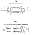
- Fig. 1 shows an outline of a double flow type low-pressure turbine rotor.
- the electrode was produced by vacuum melting of the high Cr steel rotor disk components shown in example 1, the high Cr steel rotor disk components were remelted by an ESR method and a large disk of a size for an actual machine was produced.
- a rotor shaft was produced from a low-alloy steel specified by ASTM A470Class7.
- the disk section at the last stage was joined by TIG welding and submerged arc welding so that only the disk section at the last stage is of the high Cr steel, and a block construction type turbine rotor was produced.
- the last stage section 11 is a high Cr steel disk, an upstream side 12 is made of low-alloy steel, a shaft portion 15 is made of a low-alloy steel for the purpose of reducing a damage of the bearing portion, and a material containing 1 to 2.5% of Cr is applicable.
- a welded portion 13 welding is started from an inner circumferential side, the welded portion 13 was joined by TIG welding at the initial layer through the third layer, and subsequently joined by submerged arc welding.
- Reference numeral 14 designates a void for weight reduction.
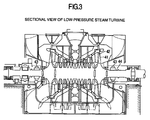
- Fig. 2 shows an outline of a single flow type high pressure-low pressure combined turbine rotor.
- the electrode was produced by vacuum melting of the high Cr steel rotor disk components shown in example 1, the high Cr steel rotor disk components were remelted by an ESR method and a large disk of a size for an actual machine was produced.
- a rotor shaft was produced from a low-pressure rotor material specified by ASTM A470Class7, and a high-pressure rotor material specified by ASTM A470Class8.
- the disk section at the last stage is joined by TIG welding and submerged arc welding so that the disk section at the last stage is made of the high Cr steel, to produce a block construction type turbine rotor.
- a final stage section 21 is a high Cr steel disk
- a high-pressure section 26 is made of ASTM A470Class8
- a low-pressure section 22 is made of ASTM A470Class7
- a shaft portion 25 is made of a low-alloy steel for the purpose of reducing damage of the bearing portion, and a material containing 1 to 2.5% Cr is applicable.
- a welded portion 23 welding was started from an inner circumferential side, the welded portion 23 was joined by TIG welding at the initial layer thorough the third layer, and subsequently joined by submerged arc welding.
- Reference numeral 24 designates a void for weight reduction.
- Fig. 3 shows a sectional view of a low-pressure steam turbine.
- a rotor 44 was constituted of a low-pressure turbine rotor shown in example 2.
- a final stage long blade 41 was produced by closed die forging with the material composition shown in example 1.
- the steam turbine rotor of the present invention can be also applied to a gas turbine compressor and the like in addition to a large steam turbine rotor, by a long blade and a rotor excellent in strength, toughness and corrosion resistance.
Description
- The present invention relates to a low-pressure turbine rotor, and to a steam turbine rotor with a large power generation capacity suitable for a large thermal power generation turbine or the like.
- In recent years, enhancement of the efficiency of thermal power generation plants has been desired from the viewpoint of energy saving (for example, saving of fossil fuel) and prevention of global warming (for example, reduction of the generation amount of CO2 gas). One of effective means for enhancing the efficiency of steam turbines is to increase the length of last stage long blades of the steam turbines. Further, by increasing the length of the last stage long blades of the steam turbines, reduction of facility construction time period and cost reduction thereby can be also expected as secondary effects because of reduction of the number of turbine casings.
- Because the long blades are used under high centrifugal stress and humid environments, the material of the long blades is required to have characteristics excellent in both strength and corrosion resistance. While rotors on which the blades are planted are also required to have high strength due to increase in size of the blades, low-pressure rotors (ASTM designation A470Class7) which are used at present are insufficient in strength. If mono-block type rotors are strengthened by heat treatment, the characteristics balance as rotors becomes worsened because the mono-block type rotors are needlessly strengthened and thus reduced in toughness except in last stages, and the sensitivity of stress-corrosion-cracking is enhanced.
-
US Pat. No. 5,906,791 andU.S. Pat. No. 5,820,817 both disclose a stainless steel with high corrosion resistance and tensile strength for use in high temperature articles comprising inter alia at least one of rare earth elements, boron, nickel (≤ 6 weight %), vanadium and aluminium in a range from 0.001 to 6 weight %. The stainless steel according toUS Pat. No. 5,906,791 further comprises at least one of rhenium, osmium, iridium, ruthenium, rhodium, platinum and palladium. -
JP H 11 350076 AEP 0 881 360 A1 andEP 1 067 206 A2 relate to steels comprising nickel in a range from 0 to 3.5 %, these steels furthermore comprising vanadium and at least one of niobium and tantalum. - The ferritic martensitic alloy for use in steam turbines according to
WO 2010/133244 A1 comprises 0,3 to 0,8 weight % nickel, a small amount of aluminium in the range from 0,05 to 0,01 weight % and vanadium and niobium. -
EP 0 831 203 A2 discloses long blades for a high and low pressure sides integrating steam turbine, each made of a martensite stainless steel comprising, by weight percentage, 0.08 - 0.18% C, not more than 0.25 % Si, not more than 0.9 % Mn, 8.0 - 13.0 % Cr, 2 - 3 % Ni, 1.5 - 3.0 % Mo, 0.05-0.35 % V, 0.02 - 0.20 % in total of at last one kind of Nb and Ta and 0.02-0.10% N. - An object of the present invention is to provide a steam turbine rotor with high reliability and responding to increase in length of a high-strength steel blade, by highly strengthening a low-pressure last stage only.
- The present invention provides a steam turbine rotor including: a steam turbine low-pressure last stage long blade made of a precipitation hardening type martensitic stainless steel containing, in mass, 0.1% or less of C, 0.1 % or less of N, 9.0% to 14.0% inclusive of Cr, 9.0% to 14.0% inclusive of Ni, 0.5% to 2.5% inclusive of Mo, 0.5% or less of Si, 1.0% or less of Mn, 0.25% to 1.75% inclusive ofTi, 0.25% to 1.75% inclusive ofAl, and the balance consisting of Fe and inevitable impurities; and a disk containing, in mass, 0.10% to 0.35% of C, 0.50% or less of Si, 0.33% or less of Mn, 8.0% to 13.0% of Cr, 0.5% to 3.5% ofNi, 1.5% to 4.0% of Mo, 0.05% to 0.35% of V, 0.02% to 0.30% in total of one kind or two kinds of Nb and Ta, 0.02% to 0.15% of N, and the balance consisting of Fe and inevitable impurities, wherein the disk is joined to a final stage section of the turbine rotor made of a low-alloy steel.
- According to the present invention, a steam turbine with high efficiency and a large capacity can be manufactured, and highly efficient power generation can be achieved, so that saving of fossil fuel and suppression in generation amount of emission gas are enabled, and a contribution can be made to global environmental conservation.
-
-
Fig. 1 is a schematic view of a block construction type low-pressure turbine rotor shaft; -
Fig. 2 is a schematic view of a block construction type high pressure-low pressure combined turbine rotor shaft; and -
Fig. 3 is a sectional view of a low-pressure steam turbine. - Hereinafter, effects and prescription of addition amounts of component elements contained in a precipitation hardening martensitic stainless steel long blade material according to the present invention will be described.
- Carbon (C) forms chromium carbide, so that reduction in toughness due to excessive precipitation of the carbide, worsening of corrosion resistance due to reduction in Cr concentration in the vicinity of a grain boundary or the like becomes a problem. Further, C significantly lowers a martensitic transformation finish point. Therefore, the amount of C needs to be reduced, and is preferably 0.1% or less, and is more preferably 0.05% or less.
- Nitrogen (N) forms TiN and AlN to reduce fatigue strength, and also has an adverse effect on toughness. Further, N significantly lowers the martensitic transformation finish point. Therefore, the amount ofN needs to be reduced, and is preferably 0.1% or less, and is more preferably 0.05% or less.
- Chrome (Cr) is an element which contributes enhancement in corrosion resistance by forming a passive film on a surface. By setting an addition lower limit at 9.0%, the corrosion resistance can be sufficiently ensured. Meanwhile, if Cr is excessively added, δ ferrite is formed so that mechanical properties and corrosion resistance are worsened significantly, and therefore, an upper limit is set at 14.0%. For the above reasons, the addition amount of Cr needs to be set at 9.0 to 14.0%. The addition amount of Cr is desirably 11.0 to 13.0%, and is preferably 11.5 to 12.5% in particular.
- Nickel (Ni) is an element which suppresses formation of δ ferrite, and contributes to enhancement in strength by precipitation hardening of Ni-Ti and Ni-Al compounds. Further, the nickel also improves a hardening property and toughness. In order to make the above described effect sufficient, an addition lower limit needs to be set at 9.0%. Meanwhile, if the addition amount exceeds 14.0%, retained austenite is formed, so that a target tensile property cannot be obtained. From the above viewpoint, the addition amount of Ni needs to be set at 9.0 to 14.0%. The addition amount of Ni is more desirably 11.0 to 12.0%, and is preferably 11.25 to 11.75% in particular.
- Molybdenum (Mo) is an element which enhances corrosion resistance. In order to obtain target corrosion resistance, addition of at least 0.5% is needed, whereas if the addition amount exceeds 2.5%, formation of δ ferrite is promoted to worsen the characteristics on the contrary. From the above viewpoint, the addition amount of Mo needs to be set at 0.5 to 2.5%. The addition amount of Mo is more desirably 1.0 to 2.0%, and is preferably 1.25 to 1.75% in particular.
- Silicon (Si) is a deoxidizer, and is preferably set at 0.5% or less. This is because if the silicon exceeds 0.5%, formation of δ ferrite becomes a problem. The silicon is more desirably set at 0.25% or less, and is preferably set at 0.1% or less in particular. If a vacuum carburized deoxidization method, and an electro-slag remelting method are applied, addition of Si can be omitted. In these cases, no addition of Si is preferable.
- Manganese (Mn) is a deoxidizer and a desulfurizing agent, and in order to suppress formation of δ ferrite, addition of at least 0.1 % or more of Mn is needed. Meanwhile, if the addition of Mn exceeds 1.0%, toughness is reduced, and therefore, 0.1 to 1.0% of Mn needs to be added. 0.3 to 0.8% of Mn is more desirable, and in particular, 0.4 to 0.7% of Mn is more preferable.
- Aluminum (Al) is an element which forms an Ni-Al compound and contributes to precipitation hardening. In order to sufficiently express precipitation hardening, at least 0.25% or more of Al needs to be added. If the addition amount exceeds 1.75%, reduction of mechanical properties due to excessive precipitation of the Ni-Al compound and formation of δ ferrite is caused. From the above viewpoint, the addition amount of Al needs to be set at 0.25 to 1.75%. The addition amount of Al is more desirably 0.5 to 1.5%, and is preferably 0.75 to 1.25% in particular.
- Titanium (Ti) forms an Ni-Ti compound and contributes to precipitation hardening. In order to obtain the above described effect sufficiently, an addition lower limit needs to be set at 0.25% or more. When Ti is excessively added, δ ferrite is formed, and therefore, the upper limit is set at 1.75%. Therefore, the addition amount of Ti needs to be set at 0.25 to 1.75%. The addition amount of Ti is more desirably 0.5 to 1.5%, and is preferably 0.75 to 1.25% in particular.
- The addition amounts of Al and Ti need to be set at 0.75 to 2.25 inclusive in total. When the total addition amount of Al and Ti is smaller than 0.75, the precipitation hardening is not sufficient, and a target tensile strength cannot be obtained. Meanwhile, when the total addition amount is larger than 2.25, the precipitation hardening becomes excessive and toughness reduces.
- Niobium (Nb) is an element which forms carbide and contributes to enhancement of strength and corrosion resistance. If the niobium is less than 0.05%, the effect thereof is insufficient, and if 0.5% or more of the niobium is added, formation of δ ferrite is promoted. From the above viewpoint, the addition amount of Nb needs to be set at 0.05 to 0.5%. The addition amount of Nb is more desirably 0.1 to 0.45%, and is preferably 0.2 to 0.3% in particular.
- Further, vanadium (V) and Tantalum (Ta) also can be replaced with Nb. When two or three kinds of Nb, V and Ta are added in combination, the total of the addition amounts needs to be the same as the amount of Nb added alone. Addition of these elements is not essential, but makes precipitation hardening more remarkable.
- Tungsten (W) has the effect of enhancing corrosion resistance similarly to Mo. Addition of W is not essential, but the effect can be further enhanced by addition in combination with Mo. In this case, the total of the addition amounts of Mo and W needs to be the same as the amount of Mo added alone in order to prevent precipitation of δ ferrite.
- In the present invention, inevitable impurities indicate components which are contained in the present invention due to the fact that the components are originally contained in a raw material, or enter the raw material in the process of manufacture, but are not intentionally included. As the inevitable impurities, P, S, Sb, Sn and As are cited, and at least one kind of them is contained in the present invention.
- Further, reduction of P and S can enhance toughness without impairing the tensile characteristics, and therefore, P and S are preferably reduced as much as possible. It is preferable from the viewpoint of enhancing the toughness to set P at 0.5% or less, and set S at 0.5% or less. In particular, P: 0.1% or less and S: 0.1% or less is preferable.
- By reducing As, Sb and Sn, toughness can be improved. Therefore, the above described elements are desired to be reduced as much as possible, and As: 0.1% or less, Sb: 0.1% or less and Sn: 0.1% or less are preferable. In particular, As: 0.05% or less, Sb: 0.05% or less and Sn: 0.05% or less are preferable.
- Even if the composition satisfies the above described component range, parameters A and B described below need to be simultaneously within the prescribed range in order to obtain a uniform tempered martensitic structure after aging thermal treatment. Note that the uniform tempered martensitic structure mentioned here indicates that the δ ferrite, the retained austenite and fresh martensite are respectively less than 10% in the structure.


- Prescribed range: 4.0≤A≤10.0 and 2.0≤B≤7.0
- A represents a parameter relating to stability of a martensitic structure. In order to obtain a uniform tempered martensitic structure, the parameter A is preferably from 4.0 to 10 inclusive in the component range of the steel of the present invention. The characteristics such as tensile strength reduce in accordance with formation of δ ferrite and the retained austenite, and therefore, the allowable amounts of them are set at 1.0% and 10% or less, respectively, from the viewpoint of safety. When the parameter A is less than 4.0, 10% or more of the retained austenite, and the austenite stabilization tendency is strong so that the martensitic transformation does not finish without sub-zero treatment even if the following parameter B is within the preset range. Therefore, austenite cannot be decomposed to 10% or less even by the ageing treatment at a temperature of Ac1 or less. Further, when the parameter A is larger than 10, 10% or more of δ ferrite forms.
- B represents a parameter relating to the transformation temperature of the invention material. In order to realize the martensitic transformation finish temperature of 20°C or higher that is a standard for obtaining a uniform tempered martensitic structure, the parameter B is preferably 2.0 or more, in the component range of the steel of the present invention. Meanwhile, when the parameter B is larger than 7.0, the Ac1 temperature becomes low, 10% or more of a fresh martensitic structure which is rigid and brittle is generated at the time of ageing treatment at 500 to 600°C that is the ageing thermal treatment temperature of the steel of the present invention, and toughness is below the target.
- From the above viewpoint, by selecting the component range which satisfies the parameter A of 4.0 to 10.0 inclusive and the parameter B of 2.0 to 7.0 inclusive, an alloy having high strength, high toughness and high corrosion resistance that becomes a uniform tempered martensitic structure can be obtained.
- The present invention provides a turbine rotor wherein a rotor disk section material contains, in mass, 0.10 to 0.35% of C, 0.50% or less of Si, 0.33% or less of Mn, 8.0 to 13.0% of Cr, 0.5 to 3.5% of Ni, 1.5 to 4.0% of Mo, 0.05 to 0.35% of V, 0.02 to 0.30% in total of one kind or two kinds of Nb and Ta, 0.02 to 0.15% of N, and the balance constituted of Fe and inevitable impurities, and is joined to a last stage section of the turbine rotor made of a low-alloy steel.
- The present invention provides a turbine rotor wherein a disk of a low-pressure last stage is welded by a melt welding method of any one of TIG welding, submerged arc welding, and shield metal arc welding.
- The present invention provides a steam turbine constituted by the above described turbine rotor, and a steam turbine power generation plant.
- A blade planted portion of a rotor has to be high in tensile strength and in corrosion resistance at the same time in order to withstand use under high centrifugal stress due to high-speed rotation and under a humid environment. Therefore, a metal structure of a turbine rotor material has to be a fully tempered martensitic structure, because if harmful δ ferrite is present, the mechanical characteristics are significantly reduced.
- High Cr steel for a disk used in the present invention needs to have components controlled so that a Cr equivalent calculated by the following expression:

- Tensile strength of the disk material at the turbine rotor last stage is 1000 MPa or more, and is preferably 1100 MPa or more.
- The reason of the component range restriction of the turbine rotor disk material of the present invention will be described. 0.15% or more of C is needed to obtain high tensile strength. If the amount of C is made too large, the toughness and weldability are reduced, and therefore, the amount of C is set at 0.35% or less. In particular, 0.16 to 0.33% is preferable, and 0.17 to 0.30% is more preferable. Further, as a result of performing further study, it is found out that even if 0.10% of C is contained, sufficiently high tensile strength can be obtained. Therefore, the component range of C is preferably 0.11 to 0.33% in particular, and is more preferably 0.12 to 0.30%.
- Si is a deoxidizer and Mn is a desulfurizing agent/deoxidizer, which are added at the time of dissolution of steel, and the effect can be obtained even by small amounts of Si and Mn. Si is a δ ferrite generating element, and addition of a large amount of Si becomes the cause of fatigue and generation of harmful δ ferrite which reduces toughness. Therefore, 0.50% or less Si is preferable. Note that according to a vacuum carburized deoxidization method, an electro-slag remelting method and the like, addition of Si is not needed, and addition of no Si is favorable. In particular, 0.10% or less is preferable, and 0.05% or less is more preferable.
- Addition of a small amount of Mn enhances toughness, whereas addition of a large amount of Mn reduces toughness, and therefore, 0.33% or less is preferable. In particular, Mn is effective as a desulfurizing agent, and therefore, from the viewpoint of enhancement of toughness, 0.30% or less is preferable, 0.25% or less is preferable in particular, and 0.20% or less is more preferable.
- Cr enhances corrosion resistance and tensile strength, but addition of 13% or more Cr causes generation of a δ ferrite structure. If addition of Cr is less than 8%, corrosion resistance is insufficient, and therefore, 8 to 13% Cr is preferable. Especially from the viewpoint of strength, 10.5 to 12.8% is preferable, and 11 to 12.5% is more preferable.
- Mo has the effect of enhancing strength by solution strengthening and carbide/nitride precipitation strengthening action. In the case of 1.5% or less of Mo, the strength enhancing effect is insufficient, and 4% or more of Mo causes δ ferrite generation. Therefore, 1.5 to 4.0% is preferable. 1.7 to 3.5% is especially preferable, and 1.9 to 3.0% is more preferable. Note that W and Co have the effect similar to Mo, and can be contained to the equivalent contents at the upper limit for the purpose of further enhancement of strength.
- V and Nb precipitate carbides and enhance tensile strength and have a toughness enhancing effect at the same time. In the case of 0.05% V and 0.02% or less of Nb, the effect thereof is insufficient, and 0.35% of V and 0.3% or less of Nb are preferable from suppression of δ ferrite formation. 0.15 to 0.30% of V is especially preferable, and 0.20 to 0.30% of V is more preferable, whereas 0.10 to 0.30 of Nb is preferable, and 0.12 to 0.22% of Nb is more preferable. In place of Nb, Ta can be added totally similarly, and in the case of combined addition, the content can be made a similar content in total.
- Ni enhances low-temperature toughness, and has an effect of preventing formation of δ ferrite. This effect is insufficient with 0.5% or less of Ni, and the effect is saturated with addition exceeding 3.5%. 0.8 to 3.2% is especially preferable, and 1.0 to 3.0% is more preferable.
- N has the effect of enhancing strength and prevention of formation of δ ferrite. However, with less than 0.02% N, the effect is not sufficient, and with N exceeding 0.15%, toughness and weldability are reduced. In particular, in the range of 0.04 to 0.10%, excellent characteristics are obtained.
- Reduction of Si, P and S has the effect of enhancing low-temperature toughness, and Si, P and S are desirably reduced as much as possible. From the viewpoint of enhancement of low-temperature toughness, Si is set at 0.50% or less, and is preferably set at 0.1% or less, P is set at 0.015% or less, and S is preferably set at 0.015% or less. 0.05% or less of Si, 0.010% or less of P and 0.010% or less of S are especially desirable.
- Reduction of Sb, Sn and As also has the effect of enhancing low-temperature toughness, and Sb, Sn and As are desired to be reduced as much as possible, but from the viewpoint of the level of the current steel manufacturing technique, Sb is limited to 0.0015% or less, Sn is limited to 0.01% or less and As is limited to 0.02% or less. In particular, 0.001% or less of Sb, 0.005% of Sn and 0.01% or less of As are desirable.
- As for welding of the turbine rotor of the present invention, it is preferable that the turbine rotor is welded by any one of TIG welding, submerged arc welding, and shield metal arc welding, and post weld heat treatment is performed at 560°C to 580°C, so that sufficient residual stress is removed, and generation of reverse transformation austenite is suppressed, whereby completely tempered martensite is applied to the disk, and tempered bainite is applied to the low-alloy rotor.
- Hereinafter, examples will be described.
- Table 1 shows a chemical composition (mass%) of a precipitation hardening type martensitic stainless steel used in a long blade member. The balance is Fe. The respective samples were subjected to 150 kg vacuum arc melting, heated to 1150°C, and forged to be provided as experimental materials. As solution heat treatment, the respective samples were kept at 950°C for one hour, and thereafter, water cooling that dips the respective samples in a room-temperature water was performed. Next, as ageing thermal treatment, the samples were kept at 500°C for 2 hours, and thereafter, air cooling for taking the samples out into the atmosphere at a room temperature was performed.
- Table 2 shows the results of a tensile test, and a V-notch Charpy impact test at a room temperature.
[Table 1] (MASS%) MATERIAL C Cr Ni Si Mn Al P S Mo Ti N A B (Al+Ti) ALLOY 1 0.01 12.1 11.1 0.002 0.05 1.3 0.002 0.002 1.4 0.65 0.002 9.0 5.1 1.9 [Table 2] MATERIAL TENSILE STRENGTH (MPa) IMPACT ABSORPTION ENERGY (J) ALLOY 1 1650 35 - Table 3 shows a chemical composition (mass%) of a high Cr steel relating to the turbine rotor disk member, and the balance is Fe. The respective samples were respectively subjected to 150 kg vacuum arc melting, heated to 1150°C, and forged to be provided as the experimental material. After the material was heated at 1050°C for two hours, the material was subjected to air blast cooling, the cooling temperature was kept at 150°C, and from that temperature, primary tempering was performed, in which after the material was heated at 560°C for two hours, the material was air-cooled. Next, secondary tempering was performed in which after the material was heated at 600°C for five hours, the material was furnace-cooled.
[Table 3] (MASS%) MATERIAL C Cr Ni Si Mn P S Mo N ROTOR 0.12 11.5 1.5 0.01 0.25 0.002 0.002 1.8 0.03 - From the raw material after heat treatment, a tensile test piece and a V notch Charpy impact test piece were sampled, and provided for the experiment.
- Table 4 shows the results of the tensile test at a room temperature, and the V notch Charpy impact test.
[Table 4] MATERIAL TENSILE STRENGTH (MPa) IMPACT ABSORPTION ENERGY (J) ROTOR 1120 42 - Both the blade material and the rotor material sufficiently satisfy the mechanical characteristics required for a large long blade.
-
Fig. 1 shows an outline of a double flow type low-pressure turbine rotor. The electrode was produced by vacuum melting of the high Cr steel rotor disk components shown in example 1, the high Cr steel rotor disk components were remelted by an ESR method and a large disk of a size for an actual machine was produced. A rotor shaft was produced from a low-alloy steel specified by ASTM A470Class7. The disk section at the last stage was joined by TIG welding and submerged arc welding so that only the disk section at the last stage is of the high Cr steel, and a block construction type turbine rotor was produced. Thelast stage section 11 is a high Cr steel disk, anupstream side 12 is made of low-alloy steel, ashaft portion 15 is made of a low-alloy steel for the purpose of reducing a damage of the bearing portion, and a material containing 1 to 2.5% of Cr is applicable. In a weldedportion 13, welding is started from an inner circumferential side, the weldedportion 13 was joined by TIG welding at the initial layer through the third layer, and subsequently joined by submerged arc welding.Reference numeral 14 designates a void for weight reduction. -
Fig. 2 shows an outline of a single flow type high pressure-low pressure combined turbine rotor. The electrode was produced by vacuum melting of the high Cr steel rotor disk components shown in example 1, the high Cr steel rotor disk components were remelted by an ESR method and a large disk of a size for an actual machine was produced. A rotor shaft was produced from a low-pressure rotor material specified by ASTM A470Class7, and a high-pressure rotor material specified by ASTM A470Class8. The disk section at the last stage is joined by TIG welding and submerged arc welding so that the disk section at the last stage is made of the high Cr steel, to produce a block construction type turbine rotor. Afinal stage section 21 is a high Cr steel disk, a high-pressure section 26 is made of ASTM A470Class8, a low-pressure section 22 is made of ASTM A470Class7, and ashaft portion 25 is made of a low-alloy steel for the purpose of reducing damage of the bearing portion, and a material containing 1 to 2.5% Cr is applicable. In a weldedportion 23, welding was started from an inner circumferential side, the weldedportion 23 was joined by TIG welding at the initial layer thorough the third layer, and subsequently joined by submerged arc welding.Reference numeral 24 designates a void for weight reduction. -
Fig. 3 shows a sectional view of a low-pressure steam turbine. Arotor 44 was constituted of a low-pressure turbine rotor shown in example 2. A final stage long blade 41 was produced by closed die forging with the material composition shown in example 1. - The steam turbine rotor of the present invention can be also applied to a gas turbine compressor and the like in addition to a large steam turbine rotor, by a long blade and a rotor excellent in strength, toughness and corrosion resistance.
Claims (7)
- A steam turbine rotor, comprising:a steam turbine low-pressure final stage long blade made of a precipitation hardening type martensitic stainless steel containing, in mass, 0.1 % or less of C, 0.1 % or less of N, 9.0% to 14.0% inclusive of Cr, 9.0% to 14.0% inclusive of Ni, 0.5% to 2.5% inclusive of Mo, 0.5% or less of Si, 1.0% or less of Mn, 0.25% to 1.75% inclusive ofTi, 0.25% to 1.75% inclusive of Al, and the balance consisting of Fe and inevitable impurities, anda disk containing, in mass, 0.10% to 0.35% of C, 0.50% or less of Si, 0.33% or less of Mn, 8.0% to 13.0% of Cr, 0.5% to 3.5% of Ni, 1.5% to 4.0% of Mo, 0.05% to 0.35% of V, 0.02% to 0.30% in total of at least one kind of Nb and Ta, 0.02% to 0.15% of N, and the balance consisting of Fe and inevitable impurities, wherein the disk is joined to a final stage section of the turbine rotor made of a low-alloy steel.
- The steam turbine rotor according to claim 1, wherein the long blade further contains, in mass, 0.5% or less of at least one kind selected from Nb, V and Ta.
- The steam turbine rotor according to claim 1 or 2, wherein the long blade further contains W, and the total amount of Mo and W is the same as the amount of Mo added alone.
- The steam turbine rotor according to any one of claims 1-3, wherein the inevitable impurities of the long blade are at least one kind selected from S, P, Sb, Sn and As, where, in mass, S: 0.5% or less, P: 0.5% or less, Sb: 0.1% or less, Sn:0.1% or less and As:0.1% or less.
- The steam turbine rotor according to any one of claims 1-4, wherein the disk of the low-pressure final stage is welded by a melt welding method of any one of TIG welding, submerged arc welding, and metal shield arc welding.
- A steam turbine, comprising the steam turbine rotor according to any one of claims 1-5.
- A steam turbine power generation plant, comprising the steam turbine according to claim 6.
Applications Claiming Priority (2)
| Application Number | Priority Date | Filing Date | Title |
|---|---|---|---|
| JP2012039523 | 2012-02-27 | ||
| JP2013005880A JP6317542B2 (en) | 2012-02-27 | 2013-01-17 | Steam turbine rotor |
Publications (2)
| Publication Number | Publication Date |
|---|---|
| EP2631432A1 EP2631432A1 (en) | 2013-08-28 |
| EP2631432B1 true EP2631432B1 (en) | 2016-07-06 |
Family
ID=47750523
Family Applications (1)
| Application Number | Title | Priority Date | Filing Date |
|---|---|---|---|
| EP13156847.9A Not-in-force EP2631432B1 (en) | 2012-02-27 | 2013-02-26 | Steam turbine rotor, corresponding steam turbine and steam turbine power generation plant |
Country Status (5)
| Country | Link |
|---|---|
| US (1) | US9200524B2 (en) |
| EP (1) | EP2631432B1 (en) |
| JP (1) | JP6317542B2 (en) |
| CN (1) | CN103290333B (en) |
| IN (1) | IN2013DE00552A (en) |
Cited By (2)
| Publication number | Priority date | Publication date | Assignee | Title |
|---|---|---|---|---|
| WO2019121866A1 (en) | 2017-12-22 | 2019-06-27 | Voestalpine Böhler Edelstahl Gmbh & Co Kg | Method for producing an article from a maraging steel |
| WO2019121879A1 (en) | 2017-12-22 | 2019-06-27 | Voestalpine Böhler Edelstahl Gmbh & Co Kg | Method for the additive manufacturing of an object from a maraging steel powder |
Families Citing this family (10)
| Publication number | Priority date | Publication date | Assignee | Title |
|---|---|---|---|---|
| JP6113456B2 (en) * | 2012-10-17 | 2017-04-12 | 三菱日立パワーシステムズ株式会社 | Precipitation hardened martensitic stainless steel and steam turbine long blades using it |
| JP6317566B2 (en) * | 2013-11-08 | 2018-04-25 | 三菱日立パワーシステムズ株式会社 | Precipitation hardening type martensitic stainless steel, turbine member using the stainless steel, and turbine using the turbine member |
| JP6189737B2 (en) * | 2013-12-18 | 2017-08-30 | 三菱日立パワーシステムズ株式会社 | Steam turbine low pressure rotor and method for manufacturing the same |
| DE102015219351A1 (en) | 2015-10-07 | 2017-04-13 | Siemens Aktiengesellschaft | Process for producing products of steel or titanium with a precipitation hardening nickel base alloy and component |
| SE540110C2 (en) * | 2016-06-01 | 2018-04-03 | Ovako Sweden Ab | High strength steel, method of manufacturing a part made of steel and use of the steel |
| CN108034798B (en) * | 2017-11-29 | 2019-06-04 | 无锡透平叶片有限公司 | A kind of heat treatment method reducing 2Cr12Ni4Mo3VNbN turbine blade yield tensile ratio |
| WO2020054540A1 (en) * | 2018-09-13 | 2020-03-19 | 大同特殊鋼株式会社 | Precipitation hardening-type martensite-based stainless steel and underground excavation drill component |
| JP7298382B2 (en) | 2018-09-13 | 2023-06-27 | 大同特殊鋼株式会社 | Precipitation Hardening Martensitic Stainless Steel and Drill Parts for Underground Drilling |
| JP7131225B2 (en) * | 2018-09-13 | 2022-09-06 | 大同特殊鋼株式会社 | Precipitation Hardening Martensitic Stainless Steel |
| WO2024013542A1 (en) * | 2022-07-12 | 2024-01-18 | Arcelormittal | Hot rolled steel and a method of manufacturing thereof |
Family Cites Families (18)
| Publication number | Priority date | Publication date | Assignee | Title |
|---|---|---|---|---|
| BE651249A (en) * | 1963-08-02 | 1964-11-16 | ||
| EP0237170B1 (en) * | 1986-02-05 | 1994-05-11 | Hitachi, Ltd. | Heat resistant steel and gas turbine composed of the same |
| JPS62180040A (en) * | 1986-02-05 | 1987-08-07 | Hitachi Ltd | Compressor blade for gas turbine |
| JPS63171856A (en) * | 1987-01-09 | 1988-07-15 | Hitachi Ltd | Heat-resisting steel and gas turbine using same |
| CN1291133C (en) * | 1996-02-16 | 2006-12-20 | 株式会社日立制作所 | Steam turbine power generating plant and steam turbine |
| JP3898785B2 (en) * | 1996-09-24 | 2007-03-28 | 株式会社日立製作所 | High and low pressure integrated steam turbine blades, high and low pressure integrated steam turbine, combined power generation system, and combined power plant |
| US5820817A (en) * | 1997-07-28 | 1998-10-13 | General Electric Company | Steel alloy |
| US5906791A (en) * | 1997-07-28 | 1999-05-25 | General Electric Company | Steel alloys |
| JPH11350076A (en) * | 1998-06-03 | 1999-12-21 | Mitsubishi Heavy Ind Ltd | Precipitation strengthening type ferritic heat resistant steel |
| JP3793667B2 (en) * | 1999-07-09 | 2006-07-05 | 株式会社日立製作所 | Method for manufacturing low-pressure steam turbine final stage rotor blade |
| JP3716684B2 (en) * | 1999-09-27 | 2005-11-16 | 株式会社日立製作所 | High strength martensitic steel |
| JP2006170006A (en) | 2004-12-14 | 2006-06-29 | Toshiba Corp | Steam turbine power generation system and low pressure turbine rotor |
| FR2887558B1 (en) * | 2005-06-28 | 2007-08-17 | Aubert & Duval Soc Par Actions | MARTENSITIC STAINLESS STEEL COMPOSITION, PROCESS FOR MANUFACTURING A MECHANICAL PART THEREFROM, AND PIECE THUS OBTAINED |
| JP4702267B2 (en) * | 2006-11-20 | 2011-06-15 | 株式会社日立製作所 | Precipitation hardening type martensitic stainless steel |
| EP2432905B1 (en) * | 2009-05-22 | 2016-04-13 | Siemens Aktiengesellschaft | Ferritic martensitic iron-based alloy, a component and a process |
| WO2012002208A1 (en) * | 2010-06-28 | 2012-01-05 | 社団法人日本航空宇宙工業会 | Precipitation-hardened stainless steel and process for production thereof |
| JP5528986B2 (en) * | 2010-11-09 | 2014-06-25 | 株式会社日立製作所 | Precipitation hardening type martensitic stainless steel and steam turbine member using the same |
| JP5409708B2 (en) * | 2011-06-16 | 2014-02-05 | 株式会社日立製作所 | Precipitation hardening type martensitic stainless steel and steam turbine long blades using the same |
-
2013
- 2013-01-17 JP JP2013005880A patent/JP6317542B2/en active Active
- 2013-02-26 CN CN201310058962.8A patent/CN103290333B/en not_active Expired - Fee Related
- 2013-02-26 US US13/777,373 patent/US9200524B2/en not_active Expired - Fee Related
- 2013-02-26 EP EP13156847.9A patent/EP2631432B1/en not_active Not-in-force
- 2013-02-26 IN IN552DE2013 patent/IN2013DE00552A/en unknown
Cited By (3)
| Publication number | Priority date | Publication date | Assignee | Title |
|---|---|---|---|---|
| WO2019121866A1 (en) | 2017-12-22 | 2019-06-27 | Voestalpine Böhler Edelstahl Gmbh & Co Kg | Method for producing an article from a maraging steel |
| WO2019121879A1 (en) | 2017-12-22 | 2019-06-27 | Voestalpine Böhler Edelstahl Gmbh & Co Kg | Method for the additive manufacturing of an object from a maraging steel powder |
| US11613790B2 (en) | 2017-12-22 | 2023-03-28 | voestalpine BOHLER Edelstahl GmbH & Co. KG | Method for producing an article from a maraging steel |
Also Published As
| Publication number | Publication date |
|---|---|
| US20130224033A1 (en) | 2013-08-29 |
| CN103290333B (en) | 2016-08-31 |
| US9200524B2 (en) | 2015-12-01 |
| IN2013DE00552A (en) | 2015-06-26 |
| EP2631432A1 (en) | 2013-08-28 |
| JP6317542B2 (en) | 2018-04-25 |
| CN103290333A (en) | 2013-09-11 |
| JP2013209742A (en) | 2013-10-10 |
Similar Documents
| Publication | Publication Date | Title |
|---|---|---|
| EP2631432B1 (en) | Steam turbine rotor, corresponding steam turbine and steam turbine power generation plant | |
| EP1669473B1 (en) | Precipitation hardened martensitic stainless steel, manufacturing method therefor, and turbine moving blade and steam turbine using the same | |
| JP5764503B2 (en) | Precipitation hardening type martensitic stainless steel, steam turbine long blade, turbine rotor and steam turbine using the same | |
| EP2546383B1 (en) | Precipitate hardening stainless steel and long blade using same for steam turbine | |
| EP1770182B1 (en) | High-strength heat resisting cast steel, method of producing the steel, and applications of the steel | |
| EP3219820B1 (en) | Nickel-base alloy-clad steel plate and method for producing the same | |
| EP1770184B1 (en) | High-strength martensite heat resisting cast steel and method of producing the steel | |
| EP2305415A1 (en) | Welding material for ni-based alloy | |
| EP2722407A2 (en) | Precipitation hardening martensitic stainless steel and long blade for steam turbine using the same | |
| EP2927337B1 (en) | Precipitation hardening type martensitic steel and process for producing same | |
| EP2377962B1 (en) | Precipitation hardenable martensitic stainless steel and steam turbine blade using the same | |
| EP2157202B1 (en) | Ferrite heat resistant steel | |
| KR20150023935A (en) | Austenitic steel alloy having excellent creep strength and resistance to oxidation and corrosion at elevated use temperatures | |
| EP3318650A1 (en) | Austenitic heat-resistant alloy and welded structure | |
| JP3962743B2 (en) | Precipitation hardening type martensitic steel, method for producing the same, turbine rotor blade and steam turbine using the same | |
| KR20130121755A (en) | Steel for stream turbine blade with excellent strength and toughness | |
| EP2915893A1 (en) | Austenitic stainless steel | |
| EP2204462A1 (en) | Ni-based alloy for a forged part of a steam turbine with excellent high temperature strength, forgeability and weldability, rotor blade of a steam turbine, stator blade of a steam turbine, screw member for a steam turbine, and pipe for a steam turbine | |
| JP6317566B2 (en) | Precipitation hardening type martensitic stainless steel, turbine member using the stainless steel, and turbine using the turbine member |
Legal Events
| Date | Code | Title | Description |
|---|---|---|---|
| PUAI | Public reference made under article 153(3) epc to a published international application that has entered the european phase |
Free format text: ORIGINAL CODE: 0009012 |
|
| 17P | Request for examination filed |
Effective date: 20130620 |
|
| AK | Designated contracting states |
Kind code of ref document: A1 Designated state(s): AL AT BE BG CH CY CZ DE DK EE ES FI FR GB GR HR HU IE IS IT LI LT LU LV MC MK MT NL NO PL PT RO RS SE SI SK SM TR |
|
| AX | Request for extension of the european patent |
Extension state: BA ME |
|
| RAP1 | Party data changed (applicant data changed or rights of an application transferred) |
Owner name: MITSUBISHI HITACHI POWER SYSTEMS, LTD. |
|
| RAP1 | Party data changed (applicant data changed or rights of an application transferred) |
Owner name: MITSUBISHI HITACHI POWER SYSTEMS, LTD. |
|
| GRAP | Despatch of communication of intention to grant a patent |
Free format text: ORIGINAL CODE: EPIDOSNIGR1 |
|
| INTG | Intention to grant announced |
Effective date: 20160215 |
|
| GRAS | Grant fee paid |
Free format text: ORIGINAL CODE: EPIDOSNIGR3 |
|
| GRAA | (expected) grant |
Free format text: ORIGINAL CODE: 0009210 |
|
| AK | Designated contracting states |
Kind code of ref document: B1 Designated state(s): AL AT BE BG CH CY CZ DE DK EE ES FI FR GB GR HR HU IE IS IT LI LT LU LV MC MK MT NL NO PL PT RO RS SE SI SK SM TR |
|
| REG | Reference to a national code |
Ref country code: GB Ref legal event code: FG4D |
|
| REG | Reference to a national code |
Ref country code: AT Ref legal event code: REF Ref document number: 810878 Country of ref document: AT Kind code of ref document: T Effective date: 20160715 Ref country code: CH Ref legal event code: EP |
|
| REG | Reference to a national code |
Ref country code: IE Ref legal event code: FG4D |
|
| REG | Reference to a national code |
Ref country code: DE Ref legal event code: R096 Ref document number: 602013009049 Country of ref document: DE |
|
| REG | Reference to a national code |
Ref country code: NL Ref legal event code: MP Effective date: 20160706 |
|
| REG | Reference to a national code |
Ref country code: LT Ref legal event code: MG4D |
|
| REG | Reference to a national code |
Ref country code: AT Ref legal event code: MK05 Ref document number: 810878 Country of ref document: AT Kind code of ref document: T Effective date: 20160706 |
|
| PG25 | Lapsed in a contracting state [announced via postgrant information from national office to epo] |
Ref country code: HR Free format text: LAPSE BECAUSE OF FAILURE TO SUBMIT A TRANSLATION OF THE DESCRIPTION OR TO PAY THE FEE WITHIN THE PRESCRIBED TIME-LIMIT Effective date: 20160706 Ref country code: IT Free format text: LAPSE BECAUSE OF FAILURE TO SUBMIT A TRANSLATION OF THE DESCRIPTION OR TO PAY THE FEE WITHIN THE PRESCRIBED TIME-LIMIT Effective date: 20160706 Ref country code: LT Free format text: LAPSE BECAUSE OF FAILURE TO SUBMIT A TRANSLATION OF THE DESCRIPTION OR TO PAY THE FEE WITHIN THE PRESCRIBED TIME-LIMIT Effective date: 20160706 Ref country code: FI Free format text: LAPSE BECAUSE OF FAILURE TO SUBMIT A TRANSLATION OF THE DESCRIPTION OR TO PAY THE FEE WITHIN THE PRESCRIBED TIME-LIMIT Effective date: 20160706 Ref country code: NL Free format text: LAPSE BECAUSE OF FAILURE TO SUBMIT A TRANSLATION OF THE DESCRIPTION OR TO PAY THE FEE WITHIN THE PRESCRIBED TIME-LIMIT Effective date: 20160706 Ref country code: NO Free format text: LAPSE BECAUSE OF FAILURE TO SUBMIT A TRANSLATION OF THE DESCRIPTION OR TO PAY THE FEE WITHIN THE PRESCRIBED TIME-LIMIT Effective date: 20161006 Ref country code: RS Free format text: LAPSE BECAUSE OF FAILURE TO SUBMIT A TRANSLATION OF THE DESCRIPTION OR TO PAY THE FEE WITHIN THE PRESCRIBED TIME-LIMIT Effective date: 20160706 Ref country code: IS Free format text: LAPSE BECAUSE OF FAILURE TO SUBMIT A TRANSLATION OF THE DESCRIPTION OR TO PAY THE FEE WITHIN THE PRESCRIBED TIME-LIMIT Effective date: 20161106 |
|
| PG25 | Lapsed in a contracting state [announced via postgrant information from national office to epo] |
Ref country code: BE Free format text: LAPSE BECAUSE OF FAILURE TO SUBMIT A TRANSLATION OF THE DESCRIPTION OR TO PAY THE FEE WITHIN THE PRESCRIBED TIME-LIMIT Effective date: 20160706 Ref country code: LV Free format text: LAPSE BECAUSE OF FAILURE TO SUBMIT A TRANSLATION OF THE DESCRIPTION OR TO PAY THE FEE WITHIN THE PRESCRIBED TIME-LIMIT Effective date: 20160706 Ref country code: AT Free format text: LAPSE BECAUSE OF FAILURE TO SUBMIT A TRANSLATION OF THE DESCRIPTION OR TO PAY THE FEE WITHIN THE PRESCRIBED TIME-LIMIT Effective date: 20160706 Ref country code: SE Free format text: LAPSE BECAUSE OF FAILURE TO SUBMIT A TRANSLATION OF THE DESCRIPTION OR TO PAY THE FEE WITHIN THE PRESCRIBED TIME-LIMIT Effective date: 20160706 Ref country code: ES Free format text: LAPSE BECAUSE OF FAILURE TO SUBMIT A TRANSLATION OF THE DESCRIPTION OR TO PAY THE FEE WITHIN THE PRESCRIBED TIME-LIMIT Effective date: 20160706 Ref country code: PL Free format text: LAPSE BECAUSE OF FAILURE TO SUBMIT A TRANSLATION OF THE DESCRIPTION OR TO PAY THE FEE WITHIN THE PRESCRIBED TIME-LIMIT Effective date: 20160706 Ref country code: GR Free format text: LAPSE BECAUSE OF FAILURE TO SUBMIT A TRANSLATION OF THE DESCRIPTION OR TO PAY THE FEE WITHIN THE PRESCRIBED TIME-LIMIT Effective date: 20161007 Ref country code: PT Free format text: LAPSE BECAUSE OF FAILURE TO SUBMIT A TRANSLATION OF THE DESCRIPTION OR TO PAY THE FEE WITHIN THE PRESCRIBED TIME-LIMIT Effective date: 20161107 |
|
| REG | Reference to a national code |
Ref country code: DE Ref legal event code: R097 Ref document number: 602013009049 Country of ref document: DE |
|
| PG25 | Lapsed in a contracting state [announced via postgrant information from national office to epo] |
Ref country code: RO Free format text: LAPSE BECAUSE OF FAILURE TO SUBMIT A TRANSLATION OF THE DESCRIPTION OR TO PAY THE FEE WITHIN THE PRESCRIBED TIME-LIMIT Effective date: 20160706 Ref country code: EE Free format text: LAPSE BECAUSE OF FAILURE TO SUBMIT A TRANSLATION OF THE DESCRIPTION OR TO PAY THE FEE WITHIN THE PRESCRIBED TIME-LIMIT Effective date: 20160706 |
|
| PLBE | No opposition filed within time limit |
Free format text: ORIGINAL CODE: 0009261 |
|
| STAA | Information on the status of an ep patent application or granted ep patent |
Free format text: STATUS: NO OPPOSITION FILED WITHIN TIME LIMIT |
|
| PG25 | Lapsed in a contracting state [announced via postgrant information from national office to epo] |
Ref country code: SM Free format text: LAPSE BECAUSE OF FAILURE TO SUBMIT A TRANSLATION OF THE DESCRIPTION OR TO PAY THE FEE WITHIN THE PRESCRIBED TIME-LIMIT Effective date: 20160706 Ref country code: BG Free format text: LAPSE BECAUSE OF FAILURE TO SUBMIT A TRANSLATION OF THE DESCRIPTION OR TO PAY THE FEE WITHIN THE PRESCRIBED TIME-LIMIT Effective date: 20161006 Ref country code: CZ Free format text: LAPSE BECAUSE OF FAILURE TO SUBMIT A TRANSLATION OF THE DESCRIPTION OR TO PAY THE FEE WITHIN THE PRESCRIBED TIME-LIMIT Effective date: 20160706 Ref country code: SK Free format text: LAPSE BECAUSE OF FAILURE TO SUBMIT A TRANSLATION OF THE DESCRIPTION OR TO PAY THE FEE WITHIN THE PRESCRIBED TIME-LIMIT Effective date: 20160706 Ref country code: DK Free format text: LAPSE BECAUSE OF FAILURE TO SUBMIT A TRANSLATION OF THE DESCRIPTION OR TO PAY THE FEE WITHIN THE PRESCRIBED TIME-LIMIT Effective date: 20160706 |
|
| 26N | No opposition filed |
Effective date: 20170407 |
|
| PG25 | Lapsed in a contracting state [announced via postgrant information from national office to epo] |
Ref country code: SI Free format text: LAPSE BECAUSE OF FAILURE TO SUBMIT A TRANSLATION OF THE DESCRIPTION OR TO PAY THE FEE WITHIN THE PRESCRIBED TIME-LIMIT Effective date: 20160706 |
|
| PG25 | Lapsed in a contracting state [announced via postgrant information from national office to epo] |
Ref country code: MC Free format text: LAPSE BECAUSE OF FAILURE TO SUBMIT A TRANSLATION OF THE DESCRIPTION OR TO PAY THE FEE WITHIN THE PRESCRIBED TIME-LIMIT Effective date: 20160706 |
|
| REG | Reference to a national code |
Ref country code: CH Ref legal event code: PL |
|
| PG25 | Lapsed in a contracting state [announced via postgrant information from national office to epo] |
Ref country code: LI Free format text: LAPSE BECAUSE OF NON-PAYMENT OF DUE FEES Effective date: 20170228 Ref country code: CH Free format text: LAPSE BECAUSE OF NON-PAYMENT OF DUE FEES Effective date: 20170228 |
|
| REG | Reference to a national code |
Ref country code: IE Ref legal event code: MM4A |
|
| REG | Reference to a national code |
Ref country code: FR Ref legal event code: ST Effective date: 20171031 |
|
| PG25 | Lapsed in a contracting state [announced via postgrant information from national office to epo] |
Ref country code: LU Free format text: LAPSE BECAUSE OF NON-PAYMENT OF DUE FEES Effective date: 20170226 |
|
| PG25 | Lapsed in a contracting state [announced via postgrant information from national office to epo] |
Ref country code: FR Free format text: LAPSE BECAUSE OF NON-PAYMENT OF DUE FEES Effective date: 20170228 |
|
| PG25 | Lapsed in a contracting state [announced via postgrant information from national office to epo] |
Ref country code: IE Free format text: LAPSE BECAUSE OF NON-PAYMENT OF DUE FEES Effective date: 20170226 |
|
| PG25 | Lapsed in a contracting state [announced via postgrant information from national office to epo] |
Ref country code: MT Free format text: LAPSE BECAUSE OF NON-PAYMENT OF DUE FEES Effective date: 20170226 |
|
| PG25 | Lapsed in a contracting state [announced via postgrant information from national office to epo] |
Ref country code: AL Free format text: LAPSE BECAUSE OF FAILURE TO SUBMIT A TRANSLATION OF THE DESCRIPTION OR TO PAY THE FEE WITHIN THE PRESCRIBED TIME-LIMIT Effective date: 20160706 |
|
| PGFP | Annual fee paid to national office [announced via postgrant information from national office to epo] |
Ref country code: DE Payment date: 20190212 Year of fee payment: 7 Ref country code: GB Payment date: 20190220 Year of fee payment: 7 |
|
| PG25 | Lapsed in a contracting state [announced via postgrant information from national office to epo] |
Ref country code: HU Free format text: LAPSE BECAUSE OF FAILURE TO SUBMIT A TRANSLATION OF THE DESCRIPTION OR TO PAY THE FEE WITHIN THE PRESCRIBED TIME-LIMIT; INVALID AB INITIO Effective date: 20130226 |
|
| PG25 | Lapsed in a contracting state [announced via postgrant information from national office to epo] |
Ref country code: CY Free format text: LAPSE BECAUSE OF NON-PAYMENT OF DUE FEES Effective date: 20160706 |
|
| PG25 | Lapsed in a contracting state [announced via postgrant information from national office to epo] |
Ref country code: MK Free format text: LAPSE BECAUSE OF FAILURE TO SUBMIT A TRANSLATION OF THE DESCRIPTION OR TO PAY THE FEE WITHIN THE PRESCRIBED TIME-LIMIT Effective date: 20160706 |
|
| PG25 | Lapsed in a contracting state [announced via postgrant information from national office to epo] |
Ref country code: TR Free format text: LAPSE BECAUSE OF FAILURE TO SUBMIT A TRANSLATION OF THE DESCRIPTION OR TO PAY THE FEE WITHIN THE PRESCRIBED TIME-LIMIT Effective date: 20160706 |
|
| REG | Reference to a national code |
Ref country code: DE Ref legal event code: R119 Ref document number: 602013009049 Country of ref document: DE |
|
| GBPC | Gb: european patent ceased through non-payment of renewal fee |
Effective date: 20200226 |
|
| PG25 | Lapsed in a contracting state [announced via postgrant information from national office to epo] |
Ref country code: GB Free format text: LAPSE BECAUSE OF NON-PAYMENT OF DUE FEES Effective date: 20200226 Ref country code: DE Free format text: LAPSE BECAUSE OF NON-PAYMENT OF DUE FEES Effective date: 20200901 |