EP2631427A2 - Balancing of Rotors - Google Patents
Balancing of Rotors Download PDFInfo
- Publication number
- EP2631427A2 EP2631427A2 EP13152815.0A EP13152815A EP2631427A2 EP 2631427 A2 EP2631427 A2 EP 2631427A2 EP 13152815 A EP13152815 A EP 13152815A EP 2631427 A2 EP2631427 A2 EP 2631427A2
- Authority
- EP
- European Patent Office
- Prior art keywords
- slot
- weight
- root
- seal wing
- notch
- Prior art date
- Legal status (The legal status is an assumption and is not a legal conclusion. Google has not performed a legal analysis and makes no representation as to the accuracy of the status listed.)
- Granted
Links
Images




Classifications
-
- F—MECHANICAL ENGINEERING; LIGHTING; HEATING; WEAPONS; BLASTING
- F01—MACHINES OR ENGINES IN GENERAL; ENGINE PLANTS IN GENERAL; STEAM ENGINES
- F01D—NON-POSITIVE DISPLACEMENT MACHINES OR ENGINES, e.g. STEAM TURBINES
- F01D5/00—Blades; Blade-carrying members; Heating, heat-insulating, cooling or antivibration means on the blades or the members
- F01D5/30—Fixing blades to rotors; Blade roots ; Blade spacers
-
- F—MECHANICAL ENGINEERING; LIGHTING; HEATING; WEAPONS; BLASTING
- F01—MACHINES OR ENGINES IN GENERAL; ENGINE PLANTS IN GENERAL; STEAM ENGINES
- F01D—NON-POSITIVE DISPLACEMENT MACHINES OR ENGINES, e.g. STEAM TURBINES
- F01D5/00—Blades; Blade-carrying members; Heating, heat-insulating, cooling or antivibration means on the blades or the members
- F01D5/02—Blade-carrying members, e.g. rotors
- F01D5/027—Arrangements for balancing
-
- F—MECHANICAL ENGINEERING; LIGHTING; HEATING; WEAPONS; BLASTING
- F01—MACHINES OR ENGINES IN GENERAL; ENGINE PLANTS IN GENERAL; STEAM ENGINES
- F01D—NON-POSITIVE DISPLACEMENT MACHINES OR ENGINES, e.g. STEAM TURBINES
- F01D5/00—Blades; Blade-carrying members; Heating, heat-insulating, cooling or antivibration means on the blades or the members
- F01D5/30—Fixing blades to rotors; Blade roots ; Blade spacers
- F01D5/3023—Fixing blades to rotors; Blade roots ; Blade spacers of radial insertion type, e.g. in individual recesses
- F01D5/303—Fixing blades to rotors; Blade roots ; Blade spacers of radial insertion type, e.g. in individual recesses in a circumferential slot
-
- F—MECHANICAL ENGINEERING; LIGHTING; HEATING; WEAPONS; BLASTING
- F01—MACHINES OR ENGINES IN GENERAL; ENGINE PLANTS IN GENERAL; STEAM ENGINES
- F01D—NON-POSITIVE DISPLACEMENT MACHINES OR ENGINES, e.g. STEAM TURBINES
- F01D5/00—Blades; Blade-carrying members; Heating, heat-insulating, cooling or antivibration means on the blades or the members
- F01D5/30—Fixing blades to rotors; Blade roots ; Blade spacers
- F01D5/3023—Fixing blades to rotors; Blade roots ; Blade spacers of radial insertion type, e.g. in individual recesses
- F01D5/303—Fixing blades to rotors; Blade roots ; Blade spacers of radial insertion type, e.g. in individual recesses in a circumferential slot
- F01D5/3038—Fixing blades to rotors; Blade roots ; Blade spacers of radial insertion type, e.g. in individual recesses in a circumferential slot the slot having inwardly directed abutment faces on both sides
-
- F—MECHANICAL ENGINEERING; LIGHTING; HEATING; WEAPONS; BLASTING
- F04—POSITIVE - DISPLACEMENT MACHINES FOR LIQUIDS; PUMPS FOR LIQUIDS OR ELASTIC FLUIDS
- F04D—NON-POSITIVE-DISPLACEMENT PUMPS
- F04D29/00—Details, component parts, or accessories
- F04D29/26—Rotors specially for elastic fluids
- F04D29/32—Rotors specially for elastic fluids for axial flow pumps
- F04D29/321—Rotors specially for elastic fluids for axial flow pumps for axial flow compressors
-
- F—MECHANICAL ENGINEERING; LIGHTING; HEATING; WEAPONS; BLASTING
- F04—POSITIVE - DISPLACEMENT MACHINES FOR LIQUIDS; PUMPS FOR LIQUIDS OR ELASTIC FLUIDS
- F04D—NON-POSITIVE-DISPLACEMENT PUMPS
- F04D29/00—Details, component parts, or accessories
- F04D29/66—Combating cavitation, whirls, noise, vibration or the like; Balancing
- F04D29/661—Combating cavitation, whirls, noise, vibration or the like; Balancing especially adapted for elastic fluid pumps
- F04D29/662—Balancing of rotors
-
- Y—GENERAL TAGGING OF NEW TECHNOLOGICAL DEVELOPMENTS; GENERAL TAGGING OF CROSS-SECTIONAL TECHNOLOGIES SPANNING OVER SEVERAL SECTIONS OF THE IPC; TECHNICAL SUBJECTS COVERED BY FORMER USPC CROSS-REFERENCE ART COLLECTIONS [XRACs] AND DIGESTS
- Y10—TECHNICAL SUBJECTS COVERED BY FORMER USPC
- Y10T—TECHNICAL SUBJECTS COVERED BY FORMER US CLASSIFICATION
- Y10T29/00—Metal working
- Y10T29/49—Method of mechanical manufacture
- Y10T29/49316—Impeller making
Definitions
- the present invention relates to rotors and in particular rotors for gas turbines and apparatus and methods for balancing a rotor.
- Gas turbine engines have rotors provided by discs or drums which rotate at many thousands of revolutions per minute.
- the discs or drums have axial or circumferential slots into which roots of aerofoils are mounted and secured. It is important that the rotor is balanced to avoid component life-limiting stresses and strains being generated.
- a balanced rotor comprising a circumferential slot and a plurality of aerofoils each secured in the slot by a respective root, the root having a root block having circumferentially facing flanks and a seal wing extending circumferentially from one of the flanks, characterised in that the seal wing has a notch engaging a balance weight positioned between adjacent roots.
- the balance weight engages the slot such that circumferential movement is inhibited through contact with the seal wing or an adjacent seal wing. In use it is desirable that the balance weight does not contact the seal wing but instead loads against a flank of the root block.
- the balance weight has a surface which abuts one of the circumferentially facing flanks of one of its adjacent roots and preferably the surface abuts the circumferentially facing flank of the root block from which the seal wing extends.
- Radial loads from the balance weight are preferably transmitted directly to walls defining the slot.
- directly it is meant that the radial loads are not transmitted through any other component, such as the root block or seal wing.
- the seal wing has a circumferentially extending edge and a radially extending edge, the notch extending into the seal wing from the circumferentially extending edge.
- the notch may not extend from the radially extending edge though it is desirable for it to do so.
- a blade for use in a balanced rotor having an aerofoil and a root having a root block having angled flanks for engaging with a circumferential slot in a gas turbine disc or drum and opposing sides connecting the angled flanks, wherein a seal wing projects from at least one of the opposing sides and has a notch for engaging a balance weight.
- the blade has a bottom edge and a side edge and the notch extends into the seal wing from the bottom edge.
- the notch also extends into the seal wing from the side edge.
- a method of assembling a rotor comprising the steps of providing a drum or disc having a circumferential slot, loading at least one blade according to any of the preceding two paragraphs into the slot, and inserting a weight into the slot, the weight engaging the notch.
- Fig. 1 depicts a typical rotor of a gas turbine having a circumferential slot for the mounting of aerofoils
- Fig. 2 depicts a typical aerofoil for mounting within the slot
- Fig. 3 depicts a perspective, plan and side view of an exemplary balance weight
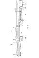
- Fig. 4 depicts a side view of the balance weight and blade located in the slot
- Fig. 5 depicts a view in the direction of arrow A in Fig. 4 ;
- Fig. 6 is top view of the weight of Fig. 4 in position in the slot;
- Fig. 7 depicts an alternative balance weight in accordance with the invention.
- Fig. 1 depicts a gas turbine compressor rotor 2 having a circumferentially extending slot 4 into which two aerofoils 6 have been mounted and a third 6' is presented for mounting.
- the slot 4 has a plurality of loading apertures 8 which are sized to permit entry of the aerofoil root 10 into the slot. Once the root is mounted in the slot it may be slid along the slot till its desired location is reached.
- Fig. 2 depicts a typical compressor blade which has an aerofoil portion 12 a platform portion 14 and a root portion 16.
- the aerofoil portion 12 has a leading edge and a trailing edge and opposing flanks, which connect between the leading and trailing edges: a concave pressure surface and a convex suction surface.
- the platform section 14 abuts the adjacent platform sections of neighbouring blades to provide a smooth, airwashed surface in use.
- the root portion 16 depends from the platform section 14 on the opposing side to the aerofoil 12.
- the root has a root block 16 which provides the necessary contact faces to react against complementary surfaces in the disc slot 4 and laterally extending seal wings 20 (one is shown) on opposing sides of the root block.
- the seal wings provide a blockage to prevent leakage of the higher pressure air flowing via the root cavity to a lower pressure zone upstream.
- the seal wings are provided with a stepped end 22 the purpose of which will be described in more detail in due course.
- FIG. 3 An embodiment of a balance weight 30 of the invention is depicted in Figure 3 in perspective, Fig. 3a , in plan, Fig. 3b and in side view, Fig. 3c .
- the weight is of a size which permits loading into the slot 4 so that it can be positioned between the root blocks 16 of adjacent blades 6.
- the axial length of the weight is sufficient to span the axial width of the slot and the weight has chamfered edges which are a point of contact between the disc and the weight such that clearance is maintained between the top 36 of the weight 30 and the underside of the seal wing 20 to ensure there is no undesired load through the seal wing.
- the chamfered edges 34 provide a surface contact with the disc rather than a point or edge contact to minimise damage or wear at the contact.
- the weight tapers towards its bottom surface 40. to prevent undesirable clashes or interference with the disc slot and reduce the possibility of friction at this location.
- the weight is held away from the base of the slot in use by the centripetal force generated from the rotating disc.
- the weight applies loads radially outwards onto both the fore and aft disc loading flanks during engine operation.
- the balance weight has a circumferential face 38 which abuts a circumferential face of the root block 16 under adverse tolerance or positioning. Beneficially, this helps to constrain the circumferential position of the balance weight.
- Fig. 5a is a view of the disc along arrow A in Figure 4 .
- Fig. 5b is an enlarged view of Figure 5a and depicts the clearance 42 of the weight 30 from the underside of the seal wing cut-out 22 and which prevents radially outward load being applied to the blade from the balance weight.
- the height 33 of the weight is sufficient to overlap with the blade root block to ensure, when the weight is positioned against the bottom of the disc slot when the engine is not rotating, that the weight is not able to slide under the root blocks of adjacent blades to a position which would upset the balance of the rotor.
- the weight When the shaft on which the rotor is mounted is spinning the weight is located radially by the contact faces of the disk flanks. When the shaft is not spinning there is space available below the weight for it to fall to the bottom of the disc slot.
- the dimensions of the insert are such that it remains in the required circumferential position so that when the shaft begins to spin again it will relocate itself in the correct radial and circumferential position.
- the weight is not locked into position but instead is circumferentially held in place by contact of one circumferential face 38 with the side face of one of the root blocks as shown in Fig. 6 and the side of the cut-out 22 in the seal wing 20.
- the contact at the circumferential face 38 is desirable to permit any forces, either steady state or impulse, are transmitted over a relatively large area. This minimises damage to either the weight or rotor blade.
- a clearance 41 is required between the side of the weight and the side of the cut-out 22 of the seal wing 20. Contact at this point could result in no contact at 38, however, the dimension 42 of the weight between the seal fins can be carefully selected during manufacture such that clearance 41 is maintained and there is no load transfer to the adjacent seal fin.
- the weight is coated in a dry film lubricant to reduce friction with the rotor or disc.
- the weights could be made from materials similar to that of the rotors e.g. titanium. However, for the balance correction to be achieved within the given volume of the insert it may be necessary to include denser material such as steel either as the whole material of the weight or as an insert coated, or alloyed in another material.
- Material can be removed from or added to the weight, particularly in the region 44 or in by adjusting the taper towards the underside of the weight.
- the shape of the weight in the region 44 may not be stepped but instead may be curved.
- the weight avoids mis-assembly as the geometry is such that it cannot be assembled into the disc slot upside down. Similarly, if installed back to front there will be a resulting gap between the annulus platforms of the adjacent blades which will be visible in assembly.
- the weight 30 is shaped such that it can be inserted between the walls of the disc slot 4 without having to be assembled through specific loading slots.
- the weight is of a general parallelogram form and can be rotated ( fig. 7b ) into place and loads outwards onto the disc flanks during operation. This assembly method can prevent the need to remove a significant number of assembled blades in order to load the weight into position thus saving a significant amount of time particularly is a number of balance iterations are required.
- a portion of the weight loads against the root block whilst a further portion extends into the seal fin cut-out to prevent rotation of the weight at rest.
- the notch or cut-out of the seal fin in which the weight is engaged may extend from a circumferentially extending edge of the seal wing but not from a radially extending edge.
Landscapes
- Engineering & Computer Science (AREA)
- Mechanical Engineering (AREA)
- General Engineering & Computer Science (AREA)
- Turbine Rotor Nozzle Sealing (AREA)
- Structures Of Non-Positive Displacement Pumps (AREA)
Abstract
Description
- The present invention relates to rotors and in particular rotors for gas turbines and apparatus and methods for balancing a rotor.
- Gas turbine engines have rotors provided by discs or drums which rotate at many thousands of revolutions per minute. The discs or drums have axial or circumferential slots into which roots of aerofoils are mounted and secured. It is important that the rotor is balanced to avoid component life-limiting stresses and strains being generated.
- Some of the methods proposed in the past to balance rotors have included special weights within the slot some of which are secured by fixings such as screws which ensure the position of the weighted components is unchanged in use and damage to adjacent components prevented. Many of these weights have the disadvantage that special tooling is required to secure the weight in its desired location and the further disadvantage that there is potential for the disc or drum to be damaged which may require the scrapping or reworking of components.
- It is an object of the present invention to seek to address these and other problems.
- According to a first aspect of the invention there is provided a balanced rotor comprising a circumferential slot and a plurality of aerofoils each secured in the slot by a respective root, the root having a root block having circumferentially facing flanks and a seal wing extending circumferentially from one of the flanks, characterised in that the seal wing has a notch engaging a balance weight positioned between adjacent roots.
- The balance weight engages the slot such that circumferential movement is inhibited through contact with the seal wing or an adjacent seal wing. In use it is desirable that the balance weight does not contact the seal wing but instead loads against a flank of the root block.
- Preferably the balance weight has a surface which abuts one of the circumferentially facing flanks of one of its adjacent roots and preferably the surface abuts the circumferentially facing flank of the root block from which the seal wing extends.
- Radial loads from the balance weight are preferably transmitted directly to walls defining the slot. By directly it is meant that the radial loads are not transmitted through any other component, such as the root block or seal wing.
- Preferably the seal wing has a circumferentially extending edge and a radially extending edge, the notch extending into the seal wing from the circumferentially extending edge. The notch may not extend from the radially extending edge though it is desirable for it to do so.
- According to a second aspect of the invention there is provided a blade for use in a balanced rotor, the blade having an aerofoil and a root having a root block having angled flanks for engaging with a circumferential slot in a gas turbine disc or drum and opposing sides connecting the angled flanks, wherein a seal wing projects from at least one of the opposing sides and has a notch for engaging a balance weight.
- Preferably the blade has a bottom edge and a side edge and the notch extends into the seal wing from the bottom edge. Preferably the notch also extends into the seal wing from the side edge.
- According to a third aspect of the invention there is provided a method of assembling a rotor comprising the steps of providing a drum or disc having a circumferential slot, loading at least one blade according to any of the preceding two paragraphs into the slot, and inserting a weight into the slot, the weight engaging the notch.
- The invention will now be described, by way of example only, and with reference to the accompanying drawings in which:
-
Fig. 1 depicts a typical rotor of a gas turbine having a circumferential slot for the mounting of aerofoils; -
Fig. 2 depicts a typical aerofoil for mounting within the slot; -
Fig. 3 depicts a perspective, plan and side view of an exemplary balance weight; -
Fig. 4 depicts a side view of the balance weight and blade located in the slot; -
Fig. 5 depicts a view in the direction of arrow A inFig. 4 ; -
Fig. 6 is top view of the weight ofFig. 4 in position in the slot; -
Fig. 7 depicts an alternative balance weight in accordance with the invention. -
Fig. 1 depicts a gasturbine compressor rotor 2 having a circumferentially extendingslot 4 into which twoaerofoils 6 have been mounted and a third 6' is presented for mounting. Theslot 4 has a plurality ofloading apertures 8 which are sized to permit entry of theaerofoil root 10 into the slot. Once the root is mounted in the slot it may be slid along the slot till its desired location is reached. - In this specification the terms axial, raidal and circumferential are used with respect to the engine as a whole, unless specifically stated otherwise.
-
Fig. 2 depicts a typical compressor blade which has an aerofoil portion 12 aplatform portion 14 and aroot portion 16. Theaerofoil portion 12 has a leading edge and a trailing edge and opposing flanks, which connect between the leading and trailing edges: a concave pressure surface and a convex suction surface. - The
platform section 14 abuts the adjacent platform sections of neighbouring blades to provide a smooth, airwashed surface in use. - The
root portion 16 depends from theplatform section 14 on the opposing side to theaerofoil 12. The root has aroot block 16 which provides the necessary contact faces to react against complementary surfaces in thedisc slot 4 and laterally extending seal wings 20 (one is shown) on opposing sides of the root block. - The seal wings provide a blockage to prevent leakage of the higher pressure air flowing via the root cavity to a lower pressure zone upstream. The seal wings are provided with a
stepped end 22 the purpose of which will be described in more detail in due course. - An embodiment of a
balance weight 30 of the invention is depicted inFigure 3 in perspective,Fig. 3a , in plan,Fig. 3b and in side view,Fig. 3c . The weight is of a size which permits loading into theslot 4 so that it can be positioned between theroot blocks 16 ofadjacent blades 6. The axial length of the weight is sufficient to span the axial width of the slot and the weight has chamfered edges which are a point of contact between the disc and the weight such that clearance is maintained between thetop 36 of theweight 30 and the underside of theseal wing 20 to ensure there is no undesired load through the seal wing. The chamferededges 34 provide a surface contact with the disc rather than a point or edge contact to minimise damage or wear at the contact. - As shown in
Figure 4 , which depicts the weight in position within the slot, the weight tapers towards itsbottom surface 40. to prevent undesirable clashes or interference with the disc slot and reduce the possibility of friction at this location. The weight is held away from the base of the slot in use by the centripetal force generated from the rotating disc. The weight applies loads radially outwards onto both the fore and aft disc loading flanks during engine operation. - The balance weight has a
circumferential face 38 which abuts a circumferential face of theroot block 16 under adverse tolerance or positioning. Beneficially, this helps to constrain the circumferential position of the balance weight. -
Fig. 5a is a view of the disc along arrow A inFigure 4 .Fig. 5b is an enlarged view ofFigure 5a and depicts theclearance 42 of theweight 30 from the underside of the seal wing cut-out 22 and which prevents radially outward load being applied to the blade from the balance weight. The height 33 of the weight is sufficient to overlap with the blade root block to ensure, when the weight is positioned against the bottom of the disc slot when the engine is not rotating, that the weight is not able to slide under the root blocks of adjacent blades to a position which would upset the balance of the rotor. - When the shaft on which the rotor is mounted is spinning the weight is located radially by the contact faces of the disk flanks. When the shaft is not spinning there is space available below the weight for it to fall to the bottom of the disc slot. The dimensions of the insert are such that it remains in the required circumferential position so that when the shaft begins to spin again it will relocate itself in the correct radial and circumferential position.
- The weight is not locked into position but instead is circumferentially held in place by contact of one
circumferential face 38 with the side face of one of the root blocks as shown inFig. 6 and the side of the cut-out 22 in theseal wing 20. The contact at thecircumferential face 38 is desirable to permit any forces, either steady state or impulse, are transmitted over a relatively large area. This minimises damage to either the weight or rotor blade. - To ensure the
mating surface 38 of the insert and the side of the rotor blade root block are parallel or flush, aclearance 41 is required between the side of the weight and the side of the cut-out 22 of theseal wing 20. Contact at this point could result in no contact at 38, however, thedimension 42 of the weight between the seal fins can be carefully selected during manufacture such thatclearance 41 is maintained and there is no load transfer to the adjacent seal fin. - The weight is coated in a dry film lubricant to reduce friction with the rotor or disc. The weights could be made from materials similar to that of the rotors e.g. titanium. However, for the balance correction to be achieved within the given volume of the insert it may be necessary to include denser material such as steel either as the whole material of the weight or as an insert coated, or alloyed in another material.
- Material can be removed from or added to the weight, particularly in the
region 44 or in by adjusting the taper towards the underside of the weight. The shape of the weight in theregion 44 may not be stepped but instead may be curved. - Beneficially, the weight avoids mis-assembly as the geometry is such that it cannot be assembled into the disc slot upside down. Similarly, if installed back to front there will be a resulting gap between the annulus platforms of the adjacent blades which will be visible in assembly.
- In an alternative form of the balance weight as shown in
Figures 7a and 7b , theweight 30 is shaped such that it can be inserted between the walls of thedisc slot 4 without having to be assembled through specific loading slots. The weight is of a general parallelogram form and can be rotated (fig. 7b ) into place and loads outwards onto the disc flanks during operation. This assembly method can prevent the need to remove a significant number of assembled blades in order to load the weight into position thus saving a significant amount of time particularly is a number of balance iterations are required. - As per the first embodiment a portion of the weight loads against the root block whilst a further portion extends into the seal fin cut-out to prevent rotation of the weight at rest.
- For this embodiment the notch or cut-out of the seal fin in which the weight is engaged may extend from a circumferentially extending edge of the seal wing but not from a radially extending edge.
Claims (10)
- A balanced rotor (2) comprising a circumferential slot (4) and a plurality of aerofoils (6) each secured in the slot by a respective root (16), the root having a root block having circumferentially facing flanks (18) and a seal wing (20) extending circumferentially from one of the flanks, characterised in that the seal wing has a notch (22) engaging a balance weight (36) positioned between adjacent roots.
- A balanced rotor according to claim 1, wherein the balance weight has a surface (38) which abuts one of the circumferentially facing flanks of one of its adjacent roots.
- A balanced rotor according to claim 2, wherein the surface abuts the circumferentially facing flank of the root block from which the seal wing extends.
- A balanced rotor according to any preceding claim, wherein radial loads from the balance weight are transmitted directly to walls defining the slot.
- A balanced rotor according to any preceding claim, wherein the seal wing has a circumferentially extending edge and a radially extending edge, the notch extending into the seal wing from the circumferentially extending edge.
- A balanced rotor according to claim 5, wherein the notch extends from the radially extending edge.
- A blade for use in a balanced rotor according to claim 1, the blade having an aerofoil and a root having a root block having angled flanks for engaging with a circumferential slot in a gas turbine disc or drum and opposing circumferentially facing flanks connecting the angled flanks, wherein a seal wing projects from at least one of the opposing circumferentially facing flanks and has a notch for engaging a balance weight.
- A blade according to claim 7, wherein the seal wing has a bottom edge and a side edge and the notch extends into the seal wing from the bottom edge.
- A blade according to claim 8, wherein the notch extends into the seal wing from the side edge.
- A method of assembling a rotor comprising the steps of providing a drum or disc having a circumferential slot, loading at least one blade according to any of claims 7 to 9 into the slot, and inserting a weight into the slot, the weight engaging the notch.
Applications Claiming Priority (1)
| Application Number | Priority Date | Filing Date | Title |
|---|---|---|---|
| GBGB1203303.1A GB201203303D0 (en) | 2012-02-27 | 2012-02-27 | Balancing of rotor |
Publications (3)
| Publication Number | Publication Date |
|---|---|
| EP2631427A2 true EP2631427A2 (en) | 2013-08-28 |
| EP2631427A3 EP2631427A3 (en) | 2017-08-16 |
| EP2631427B1 EP2631427B1 (en) | 2018-08-22 |
Family
ID=45991739
Family Applications (1)
| Application Number | Title | Priority Date | Filing Date |
|---|---|---|---|
| EP13152815.0A Active EP2631427B1 (en) | 2012-02-27 | 2013-01-28 | Balancing of Rotors |
Country Status (3)
| Country | Link |
|---|---|
| US (1) | US9382805B2 (en) |
| EP (1) | EP2631427B1 (en) |
| GB (1) | GB201203303D0 (en) |
Cited By (1)
| Publication number | Priority date | Publication date | Assignee | Title |
|---|---|---|---|---|
| CN115822730A (en) * | 2022-12-08 | 2023-03-21 | 杭州中能汽轮动力有限公司 | Steam turbine impeller structure and design and installation method thereof |
Families Citing this family (2)
| Publication number | Priority date | Publication date | Assignee | Title |
|---|---|---|---|---|
| US11377955B2 (en) | 2020-09-16 | 2022-07-05 | General Electric Company | Balancing weight entry port for turbine rotor |
| CN118836188A (en) * | 2024-07-12 | 2024-10-25 | 中国航发沈阳发动机研究所 | Aircraft engine compressor rotor balance structure |
Family Cites Families (12)
| Publication number | Priority date | Publication date | Assignee | Title |
|---|---|---|---|---|
| US3736811A (en) | 1971-08-19 | 1973-06-05 | Gen Electric | Balance weight attachment for turbine wheels |
| GB2119026B (en) * | 1981-03-25 | 1984-06-20 | Rolls Royce | Aerofoil blade mounting |
| US4743166A (en) * | 1984-12-20 | 1988-05-10 | General Electric Company | Blade root seal |
| US6279420B1 (en) * | 1999-08-18 | 2001-08-28 | General Electric Co. | Balance weight for a rotary component in turbomachinery, methods of installation and installation tools |
| DE50010348D1 (en) | 2000-03-01 | 2005-06-23 | Alstom Technology Ltd Baden | Attachment of blades in a turbomachine |
| EP1319805A1 (en) * | 2001-12-17 | 2003-06-18 | Techspace aero | Rotor or rotor element for turbocompressors |
| US6769877B2 (en) * | 2002-10-18 | 2004-08-03 | General Electric Company | Undercut leading edge for compressor blades and related method |
| US7609910B2 (en) | 2004-04-09 | 2009-10-27 | Siemens Medical Solutions Usa, Inc. | System and method for creating a panoramic view of a volumetric image |
| US20050265846A1 (en) | 2004-06-01 | 2005-12-01 | Przytulski James C | Balance assembly for rotary turbine component and method for installing and/or adjusting balance weight |
| FR2896289B1 (en) * | 2006-01-13 | 2008-03-28 | Snecma Sa | BALANCING MASSELOTTE, ROTOR DISC BEING EQUIPPED, ROTOR AND AIRCRAFT ENGINE COMPRISING THEM |
| GB0908502D0 (en) | 2009-05-19 | 2009-06-24 | Rolls Royce Plc | A balanced rotor for a turbine engine |
| US8834123B2 (en) * | 2009-12-29 | 2014-09-16 | Rolls-Royce Corporation | Turbomachinery component |
-
2012
- 2012-02-27 GB GBGB1203303.1A patent/GB201203303D0/en not_active Ceased
-
2013
- 2013-01-28 EP EP13152815.0A patent/EP2631427B1/en active Active
- 2013-01-28 US US13/751,810 patent/US9382805B2/en active Active
Cited By (1)
| Publication number | Priority date | Publication date | Assignee | Title |
|---|---|---|---|---|
| CN115822730A (en) * | 2022-12-08 | 2023-03-21 | 杭州中能汽轮动力有限公司 | Steam turbine impeller structure and design and installation method thereof |
Also Published As
| Publication number | Publication date |
|---|---|
| EP2631427A3 (en) | 2017-08-16 |
| GB201203303D0 (en) | 2012-04-11 |
| US9382805B2 (en) | 2016-07-05 |
| EP2631427B1 (en) | 2018-08-22 |
| US20130224029A1 (en) | 2013-08-29 |
Similar Documents
| Publication | Publication Date | Title |
|---|---|---|
| EP2149674B1 (en) | Bladed turbine rotor with vibration damper | |
| US9309782B2 (en) | Flat bottom damper pin for turbine blades | |
| EP2372088B1 (en) | Turbofan flow path trenches | |
| EP2500520B1 (en) | Damper and seal pin arrangement for a turbine blade | |
| US9963980B2 (en) | Turbomachine rotor blade | |
| CN103534443B (en) | The method of impeller and assembling and balance impeller | |
| JP5965616B2 (en) | Turbine blade combination damper and seal pin and related methods | |
| US9540093B2 (en) | Bladed rotor wheel for a turbine engine | |
| US9328621B2 (en) | Rotor blade assembly tool for gas turbine engine | |
| CN103244198A (en) | Turbine assembly | |
| CN107269594B (en) | Method and device for balancing a rotor | |
| US10895159B2 (en) | Removable anti-wear part for blade tip | |
| EP3464826B1 (en) | Margin bucket dovetail radial support feature for axial entry buckets | |
| EP2631427B1 (en) | Balancing of Rotors | |
| CN105229262A (en) | The corresponding method of blade system and manufacture blade system | |
| US8974185B2 (en) | Balancing of rotatable components | |
| US9664054B2 (en) | Turbomachine rotor with blade roots with adjusting protrusions | |
| CN106852162A (en) | Fin with spoiler | |
| EP2960008A1 (en) | Rotor blade manufacture | |
| CN105723053B (en) | The wheel blade locked component and fixing means of turbine | |
| EP3434864A1 (en) | A method and system for repairing a turbomachine | |
| GB2428396A (en) | A method of manufacturing an article with a reference datum feature | |
| Martseniuk et al. | Strength analysis of blade root |
Legal Events
| Date | Code | Title | Description |
|---|---|---|---|
| PUAI | Public reference made under article 153(3) epc to a published international application that has entered the european phase |
Free format text: ORIGINAL CODE: 0009012 |
|
| AK | Designated contracting states |
Kind code of ref document: A2 Designated state(s): AL AT BE BG CH CY CZ DE DK EE ES FI FR GB GR HR HU IE IS IT LI LT LU LV MC MK MT NL NO PL PT RO RS SE SI SK SM TR |
|
| AX | Request for extension of the european patent |
Extension state: BA ME |
|
| RAP1 | Party data changed (applicant data changed or rights of an application transferred) |
Owner name: ROLLS-ROYCE PLC |
|
| PUAL | Search report despatched |
Free format text: ORIGINAL CODE: 0009013 |
|
| AK | Designated contracting states |
Kind code of ref document: A3 Designated state(s): AL AT BE BG CH CY CZ DE DK EE ES FI FR GB GR HR HU IE IS IT LI LT LU LV MC MK MT NL NO PL PT RO RS SE SI SK SM TR |
|
| AX | Request for extension of the european patent |
Extension state: BA ME |
|
| RIC1 | Information provided on ipc code assigned before grant |
Ipc: F01D 5/02 20060101AFI20170713BHEP Ipc: F01D 5/30 20060101ALI20170713BHEP Ipc: F04D 29/66 20060101ALI20170713BHEP |
|
| STAA | Information on the status of an ep patent application or granted ep patent |
Free format text: STATUS: REQUEST FOR EXAMINATION WAS MADE |
|
| 17P | Request for examination filed |
Effective date: 20180214 |
|
| RBV | Designated contracting states (corrected) |
Designated state(s): AL AT BE BG CH CY CZ DE DK EE ES FI FR GB GR HR HU IE IS IT LI LT LU LV MC MK MT NL NO PL PT RO RS SE SI SK SM TR |
|
| GRAP | Despatch of communication of intention to grant a patent |
Free format text: ORIGINAL CODE: EPIDOSNIGR1 |
|
| STAA | Information on the status of an ep patent application or granted ep patent |
Free format text: STATUS: GRANT OF PATENT IS INTENDED |
|
| INTG | Intention to grant announced |
Effective date: 20180508 |
|
| GRAS | Grant fee paid |
Free format text: ORIGINAL CODE: EPIDOSNIGR3 |
|
| GRAA | (expected) grant |
Free format text: ORIGINAL CODE: 0009210 |
|
| STAA | Information on the status of an ep patent application or granted ep patent |
Free format text: STATUS: THE PATENT HAS BEEN GRANTED |
|
| AK | Designated contracting states |
Kind code of ref document: B1 Designated state(s): AL AT BE BG CH CY CZ DE DK EE ES FI FR GB GR HR HU IE IS IT LI LT LU LV MC MK MT NL NO PL PT RO RS SE SI SK SM TR |
|
| REG | Reference to a national code |
Ref country code: GB Ref legal event code: FG4D |
|
| REG | Reference to a national code |
Ref country code: CH Ref legal event code: EP |
|
| REG | Reference to a national code |
Ref country code: AT Ref legal event code: REF Ref document number: 1032762 Country of ref document: AT Kind code of ref document: T Effective date: 20180915 |
|
| REG | Reference to a national code |
Ref country code: IE Ref legal event code: FG4D |
|
| REG | Reference to a national code |
Ref country code: DE Ref legal event code: R096 Ref document number: 602013042256 Country of ref document: DE |
|
| REG | Reference to a national code |
Ref country code: NL Ref legal event code: MP Effective date: 20180822 |
|
| REG | Reference to a national code |
Ref country code: LT Ref legal event code: MG4D |
|
| PG25 | Lapsed in a contracting state [announced via postgrant information from national office to epo] |
Ref country code: FI Free format text: LAPSE BECAUSE OF FAILURE TO SUBMIT A TRANSLATION OF THE DESCRIPTION OR TO PAY THE FEE WITHIN THE PRESCRIBED TIME-LIMIT Effective date: 20180822 Ref country code: IS Free format text: LAPSE BECAUSE OF FAILURE TO SUBMIT A TRANSLATION OF THE DESCRIPTION OR TO PAY THE FEE WITHIN THE PRESCRIBED TIME-LIMIT Effective date: 20181222 Ref country code: NL Free format text: LAPSE BECAUSE OF FAILURE TO SUBMIT A TRANSLATION OF THE DESCRIPTION OR TO PAY THE FEE WITHIN THE PRESCRIBED TIME-LIMIT Effective date: 20180822 Ref country code: LT Free format text: LAPSE BECAUSE OF FAILURE TO SUBMIT A TRANSLATION OF THE DESCRIPTION OR TO PAY THE FEE WITHIN THE PRESCRIBED TIME-LIMIT Effective date: 20180822 Ref country code: BG Free format text: LAPSE BECAUSE OF FAILURE TO SUBMIT A TRANSLATION OF THE DESCRIPTION OR TO PAY THE FEE WITHIN THE PRESCRIBED TIME-LIMIT Effective date: 20181122 Ref country code: GR Free format text: LAPSE BECAUSE OF FAILURE TO SUBMIT A TRANSLATION OF THE DESCRIPTION OR TO PAY THE FEE WITHIN THE PRESCRIBED TIME-LIMIT Effective date: 20181123 Ref country code: NO Free format text: LAPSE BECAUSE OF FAILURE TO SUBMIT A TRANSLATION OF THE DESCRIPTION OR TO PAY THE FEE WITHIN THE PRESCRIBED TIME-LIMIT Effective date: 20181122 Ref country code: RS Free format text: LAPSE BECAUSE OF FAILURE TO SUBMIT A TRANSLATION OF THE DESCRIPTION OR TO PAY THE FEE WITHIN THE PRESCRIBED TIME-LIMIT Effective date: 20180822 Ref country code: SE Free format text: LAPSE BECAUSE OF FAILURE TO SUBMIT A TRANSLATION OF THE DESCRIPTION OR TO PAY THE FEE WITHIN THE PRESCRIBED TIME-LIMIT Effective date: 20180822 |
|
| REG | Reference to a national code |
Ref country code: AT Ref legal event code: MK05 Ref document number: 1032762 Country of ref document: AT Kind code of ref document: T Effective date: 20180822 |
|
| PG25 | Lapsed in a contracting state [announced via postgrant information from national office to epo] |
Ref country code: AL Free format text: LAPSE BECAUSE OF FAILURE TO SUBMIT A TRANSLATION OF THE DESCRIPTION OR TO PAY THE FEE WITHIN THE PRESCRIBED TIME-LIMIT Effective date: 20180822 Ref country code: LV Free format text: LAPSE BECAUSE OF FAILURE TO SUBMIT A TRANSLATION OF THE DESCRIPTION OR TO PAY THE FEE WITHIN THE PRESCRIBED TIME-LIMIT Effective date: 20180822 Ref country code: HR Free format text: LAPSE BECAUSE OF FAILURE TO SUBMIT A TRANSLATION OF THE DESCRIPTION OR TO PAY THE FEE WITHIN THE PRESCRIBED TIME-LIMIT Effective date: 20180822 |
|
| PG25 | Lapsed in a contracting state [announced via postgrant information from national office to epo] |
Ref country code: IT Free format text: LAPSE BECAUSE OF FAILURE TO SUBMIT A TRANSLATION OF THE DESCRIPTION OR TO PAY THE FEE WITHIN THE PRESCRIBED TIME-LIMIT Effective date: 20180822 Ref country code: PL Free format text: LAPSE BECAUSE OF FAILURE TO SUBMIT A TRANSLATION OF THE DESCRIPTION OR TO PAY THE FEE WITHIN THE PRESCRIBED TIME-LIMIT Effective date: 20180822 Ref country code: AT Free format text: LAPSE BECAUSE OF FAILURE TO SUBMIT A TRANSLATION OF THE DESCRIPTION OR TO PAY THE FEE WITHIN THE PRESCRIBED TIME-LIMIT Effective date: 20180822 Ref country code: EE Free format text: LAPSE BECAUSE OF FAILURE TO SUBMIT A TRANSLATION OF THE DESCRIPTION OR TO PAY THE FEE WITHIN THE PRESCRIBED TIME-LIMIT Effective date: 20180822 Ref country code: RO Free format text: LAPSE BECAUSE OF FAILURE TO SUBMIT A TRANSLATION OF THE DESCRIPTION OR TO PAY THE FEE WITHIN THE PRESCRIBED TIME-LIMIT Effective date: 20180822 Ref country code: CZ Free format text: LAPSE BECAUSE OF FAILURE TO SUBMIT A TRANSLATION OF THE DESCRIPTION OR TO PAY THE FEE WITHIN THE PRESCRIBED TIME-LIMIT Effective date: 20180822 Ref country code: ES Free format text: LAPSE BECAUSE OF FAILURE TO SUBMIT A TRANSLATION OF THE DESCRIPTION OR TO PAY THE FEE WITHIN THE PRESCRIBED TIME-LIMIT Effective date: 20180822 |
|
| REG | Reference to a national code |
Ref country code: DE Ref legal event code: R097 Ref document number: 602013042256 Country of ref document: DE |
|
| PG25 | Lapsed in a contracting state [announced via postgrant information from national office to epo] |
Ref country code: DK Free format text: LAPSE BECAUSE OF FAILURE TO SUBMIT A TRANSLATION OF THE DESCRIPTION OR TO PAY THE FEE WITHIN THE PRESCRIBED TIME-LIMIT Effective date: 20180822 Ref country code: SK Free format text: LAPSE BECAUSE OF FAILURE TO SUBMIT A TRANSLATION OF THE DESCRIPTION OR TO PAY THE FEE WITHIN THE PRESCRIBED TIME-LIMIT Effective date: 20180822 Ref country code: SM Free format text: LAPSE BECAUSE OF FAILURE TO SUBMIT A TRANSLATION OF THE DESCRIPTION OR TO PAY THE FEE WITHIN THE PRESCRIBED TIME-LIMIT Effective date: 20180822 |
|
| PLBE | No opposition filed within time limit |
Free format text: ORIGINAL CODE: 0009261 |
|
| STAA | Information on the status of an ep patent application or granted ep patent |
Free format text: STATUS: NO OPPOSITION FILED WITHIN TIME LIMIT |
|
| 26N | No opposition filed |
Effective date: 20190523 |
|
| PG25 | Lapsed in a contracting state [announced via postgrant information from national office to epo] |
Ref country code: MC Free format text: LAPSE BECAUSE OF FAILURE TO SUBMIT A TRANSLATION OF THE DESCRIPTION OR TO PAY THE FEE WITHIN THE PRESCRIBED TIME-LIMIT Effective date: 20180822 Ref country code: SI Free format text: LAPSE BECAUSE OF FAILURE TO SUBMIT A TRANSLATION OF THE DESCRIPTION OR TO PAY THE FEE WITHIN THE PRESCRIBED TIME-LIMIT Effective date: 20180822 |
|
| REG | Reference to a national code |
Ref country code: CH Ref legal event code: PL |
|
| PG25 | Lapsed in a contracting state [announced via postgrant information from national office to epo] |
Ref country code: LU Free format text: LAPSE BECAUSE OF NON-PAYMENT OF DUE FEES Effective date: 20190128 |
|
| REG | Reference to a national code |
Ref country code: BE Ref legal event code: MM Effective date: 20190131 |
|
| REG | Reference to a national code |
Ref country code: IE Ref legal event code: MM4A |
|
| PG25 | Lapsed in a contracting state [announced via postgrant information from national office to epo] |
Ref country code: BE Free format text: LAPSE BECAUSE OF NON-PAYMENT OF DUE FEES Effective date: 20190131 |
|
| PG25 | Lapsed in a contracting state [announced via postgrant information from national office to epo] |
Ref country code: CH Free format text: LAPSE BECAUSE OF NON-PAYMENT OF DUE FEES Effective date: 20190131 Ref country code: LI Free format text: LAPSE BECAUSE OF NON-PAYMENT OF DUE FEES Effective date: 20190131 |
|
| PG25 | Lapsed in a contracting state [announced via postgrant information from national office to epo] |
Ref country code: IE Free format text: LAPSE BECAUSE OF NON-PAYMENT OF DUE FEES Effective date: 20190128 |
|
| PG25 | Lapsed in a contracting state [announced via postgrant information from national office to epo] |
Ref country code: TR Free format text: LAPSE BECAUSE OF FAILURE TO SUBMIT A TRANSLATION OF THE DESCRIPTION OR TO PAY THE FEE WITHIN THE PRESCRIBED TIME-LIMIT Effective date: 20180822 |
|
| PG25 | Lapsed in a contracting state [announced via postgrant information from national office to epo] |
Ref country code: MT Free format text: LAPSE BECAUSE OF NON-PAYMENT OF DUE FEES Effective date: 20190128 Ref country code: PT Free format text: LAPSE BECAUSE OF FAILURE TO SUBMIT A TRANSLATION OF THE DESCRIPTION OR TO PAY THE FEE WITHIN THE PRESCRIBED TIME-LIMIT Effective date: 20181222 |
|
| PG25 | Lapsed in a contracting state [announced via postgrant information from national office to epo] |
Ref country code: CY Free format text: LAPSE BECAUSE OF FAILURE TO SUBMIT A TRANSLATION OF THE DESCRIPTION OR TO PAY THE FEE WITHIN THE PRESCRIBED TIME-LIMIT Effective date: 20180822 |
|
| PG25 | Lapsed in a contracting state [announced via postgrant information from national office to epo] |
Ref country code: HU Free format text: LAPSE BECAUSE OF FAILURE TO SUBMIT A TRANSLATION OF THE DESCRIPTION OR TO PAY THE FEE WITHIN THE PRESCRIBED TIME-LIMIT; INVALID AB INITIO Effective date: 20130128 |
|
| PG25 | Lapsed in a contracting state [announced via postgrant information from national office to epo] |
Ref country code: MK Free format text: LAPSE BECAUSE OF FAILURE TO SUBMIT A TRANSLATION OF THE DESCRIPTION OR TO PAY THE FEE WITHIN THE PRESCRIBED TIME-LIMIT Effective date: 20180822 |
|
| P01 | Opt-out of the competence of the unified patent court (upc) registered |
Effective date: 20230528 |
|
| PGFP | Annual fee paid to national office [announced via postgrant information from national office to epo] |
Ref country code: DE Payment date: 20250129 Year of fee payment: 13 |
|
| PGFP | Annual fee paid to national office [announced via postgrant information from national office to epo] |
Ref country code: FR Payment date: 20250127 Year of fee payment: 13 |
|
| PGFP | Annual fee paid to national office [announced via postgrant information from national office to epo] |
Ref country code: GB Payment date: 20260126 Year of fee payment: 14 |