EP2631423A1 - Screen apparatus and method - Google Patents
Screen apparatus and method Download PDFInfo
- Publication number
- EP2631423A1 EP2631423A1 EP12290060.8A EP12290060A EP2631423A1 EP 2631423 A1 EP2631423 A1 EP 2631423A1 EP 12290060 A EP12290060 A EP 12290060A EP 2631423 A1 EP2631423 A1 EP 2631423A1
- Authority
- EP
- European Patent Office
- Prior art keywords
- screen
- shroud
- tubes
- expanded
- expandable shroud
- Prior art date
- Legal status (The legal status is an assumption and is not a legal conclusion. Google has not performed a legal analysis and makes no representation as to the accuracy of the status listed.)
- Withdrawn
Links
Images




Classifications
-
- E—FIXED CONSTRUCTIONS
- E21—EARTH OR ROCK DRILLING; MINING
- E21B—EARTH OR ROCK DRILLING; OBTAINING OIL, GAS, WATER, SOLUBLE OR MELTABLE MATERIALS OR A SLURRY OF MINERALS FROM WELLS
- E21B43/00—Methods or apparatus for obtaining oil, gas, water, soluble or meltable materials or a slurry of minerals from wells
- E21B43/02—Subsoil filtering
- E21B43/10—Setting of casings, screens, liners or the like in wells
- E21B43/103—Setting of casings, screens, liners or the like in wells of expandable casings, screens, liners, or the like
- E21B43/108—Expandable screens or perforated liners
-
- E—FIXED CONSTRUCTIONS
- E21—EARTH OR ROCK DRILLING; MINING
- E21B—EARTH OR ROCK DRILLING; OBTAINING OIL, GAS, WATER, SOLUBLE OR MELTABLE MATERIALS OR A SLURRY OF MINERALS FROM WELLS
- E21B43/00—Methods or apparatus for obtaining oil, gas, water, soluble or meltable materials or a slurry of minerals from wells
- E21B43/02—Subsoil filtering
- E21B43/04—Gravelling of wells
-
- E—FIXED CONSTRUCTIONS
- E21—EARTH OR ROCK DRILLING; MINING
- E21B—EARTH OR ROCK DRILLING; OBTAINING OIL, GAS, WATER, SOLUBLE OR MELTABLE MATERIALS OR A SLURRY OF MINERALS FROM WELLS
- E21B43/00—Methods or apparatus for obtaining oil, gas, water, soluble or meltable materials or a slurry of minerals from wells
- E21B43/02—Subsoil filtering
- E21B43/08—Screens or liners
-
- E—FIXED CONSTRUCTIONS
- E21—EARTH OR ROCK DRILLING; MINING
- E21B—EARTH OR ROCK DRILLING; OBTAINING OIL, GAS, WATER, SOLUBLE OR MELTABLE MATERIALS OR A SLURRY OF MINERALS FROM WELLS
- E21B43/00—Methods or apparatus for obtaining oil, gas, water, soluble or meltable materials or a slurry of minerals from wells
- E21B43/02—Subsoil filtering
- E21B43/08—Screens or liners
- E21B43/088—Wire screens
-
- E—FIXED CONSTRUCTIONS
- E21—EARTH OR ROCK DRILLING; MINING
- E21B—EARTH OR ROCK DRILLING; OBTAINING OIL, GAS, WATER, SOLUBLE OR MELTABLE MATERIALS OR A SLURRY OF MINERALS FROM WELLS
- E21B43/00—Methods or apparatus for obtaining oil, gas, water, soluble or meltable materials or a slurry of minerals from wells
- E21B43/02—Subsoil filtering
- E21B43/10—Setting of casings, screens, liners or the like in wells
- E21B43/103—Setting of casings, screens, liners or the like in wells of expandable casings, screens, liners, or the like
Definitions
- Tubes are placed along the screen length and interconnected like shunt tubes. While inflating those tubes, they will expand the shroud until it touches the formation. Those tubes can be used as well for gravel pack operation. In case only fluid is used to expand those tubes, a check valve or sliding sleeve will ensure that fluid trapped inside that expanded tube is trapped inside preventing the shroud to collapse. If shroud is holding the formation in place, it acts as a compliant screen. The screen retains solids. In some embodiments, the screen apparatus and method of the invention would maintain the near well bore in place similar to an expandable or compliant screen but will not have the filter media pushed out against the open hole. This will allow very high compression rating, more robust filter media, and even the ability to gravel pack the open hole while maintaining the screens centered.
- a screen is provided as shown in Figure 1 .
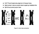
- FIG. 3 shows the shunt tube connection on a screen.
- This shunt tube connection can be also optimized to have it simplified. As long as there is continuity in the tubes and as long as it seals, this concept will work.
- the screen is run in an open hole section in a similar way as standard screens.
- Figures 4 and 5 show the screen in the open hole section with collapsed tubes in their initial position.
- the collapsed tubes When in position, the collapsed tubes are inflated and serve multiple purposes:
- the shroud now touches the open hole formation and consolidate the well bore to keep it stable and prevent any collapse of the well bore
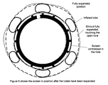
- Figure 6 is a cross section of the tubes expanded and pushing the shroud against the formation.
- Figure 7 shows the screen being centralized along the entire length of the open hole, and inflated in one step.
- the screen apparatus and method of the invention provide the following:
Landscapes
- Geology (AREA)
- Life Sciences & Earth Sciences (AREA)
- Engineering & Computer Science (AREA)
- Mining & Mineral Resources (AREA)
- Environmental & Geological Engineering (AREA)
- Fluid Mechanics (AREA)
- Physics & Mathematics (AREA)
- General Life Sciences & Earth Sciences (AREA)
- Geochemistry & Mineralogy (AREA)
- Chemical & Material Sciences (AREA)
- Dispersion Chemistry (AREA)
- Filtration Of Liquid (AREA)
- Investigation Of Foundation Soil And Reinforcement Of Foundation Soil By Compacting Or Drainage (AREA)
- Pipe Accessories (AREA)
Abstract
A screen apparatus comprising a base pipe, a filtering media, an expandable shroud, and an inflatable tube positioned in the annular space between the expandable shroud and the filter media, wherein the expandable shroud has an initial position and an expanded position, and wherein the expandable shroud is moved from the initial position to the expanded position by inflating the inflatable tube from a collapsed position to an inflated position.
Description
- Tubes are placed along the screen length and interconnected like shunt tubes. While inflating those tubes, they will expand the shroud until it touches the formation. Those tubes can be used as well for gravel pack operation. In case only fluid is used to expand those tubes, a check valve or sliding sleeve will ensure that fluid trapped inside that expanded tube is trapped inside preventing the shroud to collapse. If shroud is holding the formation in place, it acts as a compliant screen. The screen retains solids. In some embodiments, the screen apparatus and method of the invention would maintain the near well bore in place similar to an expandable or compliant screen but will not have the filter media pushed out against the open hole. This will allow very high compression rating, more robust filter media, and even the ability to gravel pack the open hole while maintaining the screens centered.
- The invention will further be described, by way of example, with reference to the accompanying drawings, in which:
-
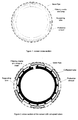
Figure 1 is a cross sectional view of a screen; -
Figure 2 is a cross sectional view of the screen with collapsed tubes; -
Figure 3 shows the shunt tube connection; -
Figure 4 shows a new screen running in open hole section; -
Figure 5 shows a screen in position not expanded against the well bore; -
Figure 6 shows the screen in position after the tubes have been expanded; -
Figure 7 shows screens centralized and the shroud touching the open hole; -
Figure 8 shows a check valve or sliding sleeve closing the tubes expanded; -
Figure 9 shows an expanded screen and gravel packed operated through the expanded tubes; and -
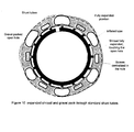
Figure 10 shows an expanded shroud and gravel pack through standard shunt tubes. - In some embodiments, a screen is provided as shown in
Figure 1 . - From this screen, as shown in
Figure 1 , collapsed tubes are added between the shroud and the base pipe. This is shown inFigure 2 . - Those collapsed tubes are running along each screen and are connected between each other.
Figure 3 shows the shunt tube connection on a screen. - This shunt tube connection can be also optimized to have it simplified. As long as there is continuity in the tubes and as long as it seals, this concept will work.
- The screen is run in an open hole section in a similar way as standard screens.
Figures 4 and5 show the screen in the open hole section with collapsed tubes in their initial position. - When in position, the collapsed tubes are inflated and serve multiple purposes:
- 1/ Centralization of the screen on its entire length in one operation
- 2/ Expansion of the shroud.
- The shroud now touches the open hole formation and consolidate the well bore to keep it stable and prevent any collapse of the well bore
-
Figure 6 is a cross section of the tubes expanded and pushing the shroud against the formation. -
Figure 7 shows the screen being centralized along the entire length of the open hole, and inflated in one step. - From this step, at least 2 options are feasible:
- Option 1: Leave the screen as it is, and in this case, lock the tubes inflated by the use of a check valve or a sliding sleeve, as shown in
Figure 8 . This would prevent the tubes to be deflated and in case of formation collapse, it would help the support the shroud. - Option 2: use those expanded tubes as gravel pack tubes and gravel pack the inside space between the shroud and the screen. This would provide a perfect gravel pack of the screen, holding the formation to collapse the shroud.
Figure 9 shows the cross section of the screens expanded and gravel packed. - The other alternative is to use standard shunt tubes to perform the gravel pack operation. In this case, the expanded tubes can stay inflated, but there should be no need to close them as the collapse rating will most likely be obtained with the gravel.
Figure 10 shows this solution. - In some embodiments, the screen apparatus and method of the invention provide the following:
- Compliant shroud to maintain the formation in place
- Deployed in one step by pressure increase of the tubes.
- Tubes do support the formation from collapse pressure either because they are full of fluid and closed or full of proppant (gravel pack option).
- Screens are centralized in the open hole
- Screen can comprise either premium screen, or wire wrap
- Expanded tubes can be used for gravel pack operation
- It is possible to gravel pack the space between the screen and the shroud
- Another option is to use premium mesh below the shroud and therefore have a dual screen system: a premium screen would be expanded and touching the formation when a standard screen would be on the base pipe.
- If formation collapses the shroud, the screen will still work as a standard screen with shroud.
Claims (3)
- A screen apparatus comprising a base pipe, a filtering media, an expandable shroud, and an inflatable tube positioned in the annular space between the expandable shroud and the filter media, wherein the expandable shroud has an initial position and an expanded position, and wherein the expandable shroud is moved from the initial position to the expanded position by inflating the inflatable tube from a collapsed position to an inflated position.
- A method comprising running into a wellbore a screen apparatus comprising a base pipe, a filtering media, an expandable shroud, and an inflatable tube positioned in the annular space between the expandable shroud and the filter media, and inflating the inflatable tube from a collapsed position to an inflated position to move the expandable shroud from an initial position to an expanded position.
- The method of claim 2 further comprising flowing a gravel slurry through the inflatable tube to gravel pack the annular space between the filter media and the expandable shroud.
Priority Applications (5)
| Application Number | Priority Date | Filing Date | Title |
|---|---|---|---|
| EP12290060.8A EP2631423A1 (en) | 2012-02-23 | 2012-02-23 | Screen apparatus and method |
| US13/707,011 US9677387B2 (en) | 2012-02-23 | 2012-12-06 | Screen assembly |
| PCT/US2013/025501 WO2013126227A1 (en) | 2012-02-23 | 2013-02-11 | Screen assembly |
| SG11201404878PA SG11201404878PA (en) | 2012-02-23 | 2013-02-11 | Screen assembly |
| EP13751724.9A EP2817483A4 (en) | 2012-02-23 | 2013-02-11 | Screen assembly |
Applications Claiming Priority (1)
| Application Number | Priority Date | Filing Date | Title |
|---|---|---|---|
| EP12290060.8A EP2631423A1 (en) | 2012-02-23 | 2012-02-23 | Screen apparatus and method |
Publications (1)
| Publication Number | Publication Date |
|---|---|
| EP2631423A1 true EP2631423A1 (en) | 2013-08-28 |
Family
ID=45928749
Family Applications (2)
| Application Number | Title | Priority Date | Filing Date |
|---|---|---|---|
| EP12290060.8A Withdrawn EP2631423A1 (en) | 2012-02-23 | 2012-02-23 | Screen apparatus and method |
| EP13751724.9A Withdrawn EP2817483A4 (en) | 2012-02-23 | 2013-02-11 | Screen assembly |
Family Applications After (1)
| Application Number | Title | Priority Date | Filing Date |
|---|---|---|---|
| EP13751724.9A Withdrawn EP2817483A4 (en) | 2012-02-23 | 2013-02-11 | Screen assembly |
Country Status (4)
| Country | Link |
|---|---|
| US (1) | US9677387B2 (en) |
| EP (2) | EP2631423A1 (en) |
| SG (1) | SG11201404878PA (en) |
| WO (1) | WO2013126227A1 (en) |
Cited By (5)
| Publication number | Priority date | Publication date | Assignee | Title |
|---|---|---|---|---|
| GB2504234A (en) * | 2012-03-07 | 2014-01-22 | Darcy Technologies Ltd | Sand screen with inflatable chamber |
| CN104763389A (en) * | 2014-01-03 | 2015-07-08 | 韦特福特/兰姆有限公司 | High-speed injection screen assembly with non-return ports |
| GB2603587A (en) * | 2020-11-19 | 2022-08-10 | Schlumberger Technology Bv | Multi-zone sand screen with alternate path functionality |
| US12078036B2 (en) | 2020-04-08 | 2024-09-03 | Schlumberger Technology Corporation | Single trip wellbore completion system |
| US12134959B2 (en) | 2020-04-15 | 2024-11-05 | Schlumberger Technology Corporation | Multi-trip wellbore completion system with a service string |
Families Citing this family (17)
| Publication number | Priority date | Publication date | Assignee | Title |
|---|---|---|---|---|
| SG11201505335XA (en) * | 2013-01-31 | 2015-08-28 | Halliburton Energy Services Inc | Spring clips for tubular connection |
| US8931568B2 (en) * | 2013-03-14 | 2015-01-13 | Weatherford/Lamb, Inc. | Shunt tube connections for wellscreen assembly |
| GB201323121D0 (en) | 2013-12-30 | 2014-02-12 | Darcy Technologies Ltd | Downhole Apparatus |
| GB201323127D0 (en) * | 2013-12-30 | 2014-02-12 | Darcy Technologies Ltd | Downhole apparatus |
| CA2937378C (en) | 2014-02-24 | 2017-01-03 | Delta Screen & Filtration, Llc | Shunt tube connector assembly and method |
| US11840905B2 (en) * | 2014-10-08 | 2023-12-12 | Weatherford Technology Holdings, Llc | Stage tool |
| US10815766B2 (en) | 2015-02-27 | 2020-10-27 | Schlumberger Technology Corporation | Vertical drilling and fracturing methodology |
| EP3510244A4 (en) * | 2016-09-09 | 2020-04-29 | Services Petroliers Schlumberger | DRILLING AND SIMULATION OF UNDERGROUND FORMATION |
| US11840909B2 (en) | 2016-09-12 | 2023-12-12 | Schlumberger Technology Corporation | Attaining access to compromised fractured production regions at an oilfield |
| EA201991640A1 (en) | 2017-01-04 | 2019-11-29 | LINE INTENSIFICATION, INCLUDING HYDRAULIC BREAKTHROUGH LAYER THROUGH SPEED CHANNELS | |
| WO2018186836A1 (en) * | 2017-04-04 | 2018-10-11 | Delta Screen & Filtration, Llc | Jumper tube connector/connection apparatus and methods |
| US11203901B2 (en) | 2017-07-10 | 2021-12-21 | Schlumberger Technology Corporation | Radial drilling link transmission and flex shaft protective cover |
| WO2019014161A1 (en) | 2017-07-10 | 2019-01-17 | Schlumberger Technology Corporation | Controlled release of hose |
| US11193332B2 (en) | 2018-09-13 | 2021-12-07 | Schlumberger Technology Corporation | Slider compensated flexible shaft drilling system |
| GB2610779B (en) * | 2020-07-20 | 2024-08-07 | Halliburton Energy Services Inc | Hydraulic screen with flow control device module |
| US11719076B2 (en) * | 2020-07-31 | 2023-08-08 | Halliburton Energy Services, Inc. | Hydraulic screen having a joint with a flow path |
| US11725487B2 (en) * | 2021-02-04 | 2023-08-15 | Baker Hughes Oilfield Operations Llc | Conformable sand screen |
Citations (4)
| Publication number | Priority date | Publication date | Assignee | Title |
|---|---|---|---|---|
| US20020088744A1 (en) * | 2001-01-11 | 2002-07-11 | Echols Ralph H. | Well screen having a line extending therethrough |
| US20070084608A1 (en) * | 2001-01-16 | 2007-04-19 | Schlumberger Technology Corporation | Screen and Method Having a Partial Screen Wrap |
| WO2009001069A2 (en) * | 2007-06-26 | 2008-12-31 | Paul David Metcalfe | Permeability modification |
| WO2012066290A2 (en) | 2010-11-16 | 2012-05-24 | Darcy Technologies Limited | Downhole method and apparatus |
Family Cites Families (45)
| Publication number | Priority date | Publication date | Assignee | Title |
|---|---|---|---|---|
| US4260016A (en) | 1980-02-28 | 1981-04-07 | Texaco Inc. | Self-cleaning helical spring sand screen |
| US4421165A (en) * | 1980-07-15 | 1983-12-20 | Halliburton Company | Multiple stage cementer and casing inflation packer |
| GB9117683D0 (en) * | 1991-08-16 | 1991-10-02 | Head Philip F | Well packer |
| FR2704898B1 (en) * | 1993-05-03 | 1995-08-04 | Drillflex | TUBULAR STRUCTURE OF PREFORM OR MATRIX FOR TUBING A WELL. |
| US5390966A (en) | 1993-10-22 | 1995-02-21 | Mobil Oil Corporation | Single connector for shunt conduits on well tool |
| US5515915A (en) | 1995-04-10 | 1996-05-14 | Mobil Oil Corporation | Well screen having internal shunt tubes |
| US5588487A (en) | 1995-09-12 | 1996-12-31 | Mobil Oil Corporation | Tool for blocking axial flow in gravel-packed well annulus |
| US5868200A (en) | 1997-04-17 | 1999-02-09 | Mobil Oil Corporation | Alternate-path well screen having protected shunt connection |
| US5890533A (en) | 1997-07-29 | 1999-04-06 | Mobil Oil Corporation | Alternate path well tool having an internal shunt tube |
| FR2791732B1 (en) * | 1999-03-29 | 2001-08-10 | Cooperation Miniere Et Ind Soc | BLOCKING DEVICE OF A WELLBORE |
| US6457518B1 (en) | 2000-05-05 | 2002-10-01 | Halliburton Energy Services, Inc. | Expandable well screen |
| US6799637B2 (en) | 2000-10-20 | 2004-10-05 | Schlumberger Technology Corporation | Expandable tubing and method |
| US6530574B1 (en) * | 2000-10-06 | 2003-03-11 | Gary L. Bailey | Method and apparatus for expansion sealing concentric tubular structures |
| US6725934B2 (en) * | 2000-12-21 | 2004-04-27 | Baker Hughes Incorporated | Expandable packer isolation system |
| US6557634B2 (en) | 2001-03-06 | 2003-05-06 | Halliburton Energy Services, Inc. | Apparatus and method for gravel packing an interval of a wellbore |
| US6510896B2 (en) | 2001-05-04 | 2003-01-28 | Weatherford/Lamb, Inc. | Apparatus and methods for utilizing expandable sand screen in wellbores |
| US6581689B2 (en) | 2001-06-28 | 2003-06-24 | Halliburton Energy Services, Inc. | Screen assembly and method for gravel packing an interval of a wellbore |
| US6752207B2 (en) | 2001-08-07 | 2004-06-22 | Schlumberger Technology Corporation | Apparatus and method for alternate path system |
| US6837308B2 (en) * | 2001-08-10 | 2005-01-04 | Bj Services Company | Apparatus and method for gravel packing |
| US20040007829A1 (en) * | 2001-09-07 | 2004-01-15 | Ross Colby M. | Downhole seal assembly and method for use of same |
| US7036600B2 (en) * | 2002-08-01 | 2006-05-02 | Schlumberger Technology Corporation | Technique for deploying expandables |
| GB0303152D0 (en) * | 2003-02-12 | 2003-03-19 | Weatherford Lamb | Seal |
| US6994170B2 (en) | 2003-05-29 | 2006-02-07 | Halliburton Energy Services, Inc. | Expandable sand control screen assembly having fluid flow control capabilities and method for use of same |
| EA008205B1 (en) | 2003-08-25 | 2007-04-27 | Джеффри А. Спрей | Expandable tubulars for use in geologic structures, methods for expanding tubulars, and methods of manufacturing expandable tubulars |
| US7380595B2 (en) | 2004-01-21 | 2008-06-03 | Schlumberger Technology Corporation | System and method to deploy and expand tubular components deployed through tubing |
| US7866708B2 (en) | 2004-03-09 | 2011-01-11 | Schlumberger Technology Corporation | Joining tubular members |
| US7665537B2 (en) * | 2004-03-12 | 2010-02-23 | Schlumbeger Technology Corporation | System and method to seal using a swellable material |
| GB0417328D0 (en) * | 2004-08-04 | 2004-09-08 | Read Well Services Ltd | Apparatus and method |
| US20060042801A1 (en) * | 2004-08-24 | 2006-03-02 | Hackworth Matthew R | Isolation device and method |
| US7591321B2 (en) * | 2005-04-25 | 2009-09-22 | Schlumberger Technology Corporation | Zonal isolation tools and methods of use |
| US20070089909A1 (en) | 2005-10-07 | 2007-04-26 | M-I Llc | Mechanically modified filter cake |
| WO2007106429A2 (en) * | 2006-03-10 | 2007-09-20 | Dynamic Tubular Systems, Inc. | Expandable tubulars for use in geologic structures |
| US7562709B2 (en) * | 2006-09-19 | 2009-07-21 | Schlumberger Technology Corporation | Gravel pack apparatus that includes a swellable element |
| US7938184B2 (en) | 2006-11-15 | 2011-05-10 | Exxonmobil Upstream Research Company | Wellbore method and apparatus for completion, production and injection |
| US7661476B2 (en) | 2006-11-15 | 2010-02-16 | Exxonmobil Upstream Research Company | Gravel packing methods |
| US20080289815A1 (en) | 2007-05-22 | 2008-11-27 | Schlumberger Technology Corporation | Downhole screen assembly |
| US7828056B2 (en) | 2007-07-06 | 2010-11-09 | Schlumberger Technology Corporation | Method and apparatus for connecting shunt tubes to sand screen assemblies |
| US7841409B2 (en) | 2008-08-29 | 2010-11-30 | Halliburton Energy Services, Inc. | Sand control screen assembly and method for use of same |
| US7866383B2 (en) | 2008-08-29 | 2011-01-11 | Halliburton Energy Services, Inc. | Sand control screen assembly and method for use of same |
| US8230935B2 (en) * | 2009-10-09 | 2012-07-31 | Halliburton Energy Services, Inc. | Sand control screen assembly with flow control capability |
| US9267360B2 (en) | 2011-04-01 | 2016-02-23 | Schlumberger Technology Corporation | Premium mesh screen |
| GB2504234B (en) * | 2012-03-07 | 2015-12-02 | Darcy Technologies Ltd | Downhole apparatus |
| GB201210532D0 (en) | 2012-06-14 | 2012-07-25 | Darcy Technologies Ltd | Subterranean formation methods and apparatus |
| US9399902B2 (en) * | 2013-01-08 | 2016-07-26 | Halliburton Energy Services, Inc. | Expandable screen completion tool |
| AU2013385681B2 (en) * | 2013-04-01 | 2017-02-23 | Halliburton Energy Services, Inc. | Well screen assembly with extending screen |
-
2012
- 2012-02-23 EP EP12290060.8A patent/EP2631423A1/en not_active Withdrawn
- 2012-12-06 US US13/707,011 patent/US9677387B2/en not_active Expired - Fee Related
-
2013
- 2013-02-11 EP EP13751724.9A patent/EP2817483A4/en not_active Withdrawn
- 2013-02-11 SG SG11201404878PA patent/SG11201404878PA/en unknown
- 2013-02-11 WO PCT/US2013/025501 patent/WO2013126227A1/en not_active Ceased
Patent Citations (5)
| Publication number | Priority date | Publication date | Assignee | Title |
|---|---|---|---|---|
| US20020088744A1 (en) * | 2001-01-11 | 2002-07-11 | Echols Ralph H. | Well screen having a line extending therethrough |
| US20070084608A1 (en) * | 2001-01-16 | 2007-04-19 | Schlumberger Technology Corporation | Screen and Method Having a Partial Screen Wrap |
| WO2009001069A2 (en) * | 2007-06-26 | 2008-12-31 | Paul David Metcalfe | Permeability modification |
| WO2009001073A2 (en) | 2007-06-26 | 2008-12-31 | Paul David Metcalfe | Downhole apparatus |
| WO2012066290A2 (en) | 2010-11-16 | 2012-05-24 | Darcy Technologies Limited | Downhole method and apparatus |
Cited By (13)
| Publication number | Priority date | Publication date | Assignee | Title |
|---|---|---|---|---|
| US9851852B2 (en) | 2012-03-07 | 2017-12-26 | Darcy Technologies Limited | Downhole apparatus |
| US10613691B2 (en) | 2012-03-07 | 2020-04-07 | Halliburton Manufacturing And Services Limited | Downhole apparatus |
| GB2504234B (en) * | 2012-03-07 | 2015-12-02 | Darcy Technologies Ltd | Downhole apparatus |
| GB2504234A (en) * | 2012-03-07 | 2014-01-22 | Darcy Technologies Ltd | Sand screen with inflatable chamber |
| CN104763389B (en) * | 2014-01-03 | 2019-01-08 | 韦特福特/兰姆有限公司 | High-speed injection screen assembly with non-return ports |
| US9695675B2 (en) | 2014-01-03 | 2017-07-04 | Weatherford Technology Holdings, Llc | High-rate injection screen assembly with checkable ports |
| EP2891763A3 (en) * | 2014-01-03 | 2016-05-25 | Weatherford/Lamb Inc. | High-rate injection screen with checkable ports |
| CN104763389A (en) * | 2014-01-03 | 2015-07-08 | 韦特福特/兰姆有限公司 | High-speed injection screen assembly with non-return ports |
| US12078036B2 (en) | 2020-04-08 | 2024-09-03 | Schlumberger Technology Corporation | Single trip wellbore completion system |
| US12134959B2 (en) | 2020-04-15 | 2024-11-05 | Schlumberger Technology Corporation | Multi-trip wellbore completion system with a service string |
| GB2603587A (en) * | 2020-11-19 | 2022-08-10 | Schlumberger Technology Bv | Multi-zone sand screen with alternate path functionality |
| GB2603587B (en) * | 2020-11-19 | 2023-03-08 | Schlumberger Technology Bv | Multi-zone sand screen with alternate path functionality |
| US11753908B2 (en) | 2020-11-19 | 2023-09-12 | Schlumberger Technology Corporation | Multi-zone sand screen with alternate path functionality |
Also Published As
| Publication number | Publication date |
|---|---|
| US20130220606A1 (en) | 2013-08-29 |
| EP2817483A1 (en) | 2014-12-31 |
| WO2013126227A1 (en) | 2013-08-29 |
| US9677387B2 (en) | 2017-06-13 |
| EP2817483A4 (en) | 2016-07-20 |
| SG11201404878PA (en) | 2014-09-26 |
Similar Documents
| Publication | Publication Date | Title |
|---|---|---|
| EP2631423A1 (en) | Screen apparatus and method | |
| CN106068364B (en) | Downhole apparatus | |
| US10151168B2 (en) | Downhole expandable tubular | |
| EP2176513B1 (en) | Permeability modification | |
| US9163468B2 (en) | Expandable casing patch | |
| CA2860300C (en) | Expandable tubing run through production tubing and into open hole | |
| US7380595B2 (en) | System and method to deploy and expand tubular components deployed through tubing | |
| US20070056743A1 (en) | Method of radially expanding and plastically deforming tubular members | |
| US20050173108A1 (en) | Method of forming a mono diameter wellbore casing | |
| CN110709578A (en) | Downhole patch installation tool | |
| CN106460480A (en) | Downhole expandable metal tubular | |
| CN104169519A (en) | Annular barrier having flexible connection | |
| AU2015416689B2 (en) | Wellbore isolation device | |
| CN104265218A (en) | Expansion type hanger | |
| WO2010059535A2 (en) | Enhanced jack for drawing a mandrel | |
| CN204113166U (en) | Expansion hanger | |
| US20050139394A1 (en) | Expandable screen utilizing near neutrally-buoyant particles outside of the screen | |
| WO2015176369A1 (en) | Expandable sand screen | |
| EP2888435B1 (en) | Plugging device | |
| CA2852351C (en) | Combined casing system and method | |
| CN113756778B (en) | Composite completion string and how to use it | |
| CN203412559U (en) | Sand control well completion tool of underground drawing expansion sand filtering pipe |
Legal Events
| Date | Code | Title | Description |
|---|---|---|---|
| PUAI | Public reference made under article 153(3) epc to a published international application that has entered the european phase |
Free format text: ORIGINAL CODE: 0009012 |
|
| AK | Designated contracting states |
Kind code of ref document: A1 Designated state(s): AL AT BE BG CH CY CZ DE DK EE ES FI FR GB GR HR HU IE IS IT LI LT LU LV MC MK MT NL NO PL PT RO RS SE SI SK SM TR |
|
| AX | Request for extension of the european patent |
Extension state: BA ME |
|
| TPAA | Information related to observations by third parties modified |
Free format text: ORIGINAL CODE: EPIDOSCTIPA |
|
| TPAC | Observations filed by third parties |
Free format text: ORIGINAL CODE: EPIDOSNTIPA |
|
| STAA | Information on the status of an ep patent application or granted ep patent |
Free format text: STATUS: THE APPLICATION IS DEEMED TO BE WITHDRAWN |
|
| 18D | Application deemed to be withdrawn |
Effective date: 20140301 |