EP2631399A2 - Latch assembly and latchbolt - Google Patents
Latch assembly and latchbolt Download PDFInfo
- Publication number
- EP2631399A2 EP2631399A2 EP13155307.5A EP13155307A EP2631399A2 EP 2631399 A2 EP2631399 A2 EP 2631399A2 EP 13155307 A EP13155307 A EP 13155307A EP 2631399 A2 EP2631399 A2 EP 2631399A2
- Authority
- EP
- European Patent Office
- Prior art keywords
- head assembly
- latchbolt
- casing
- assembly
- head
- Prior art date
- Legal status (The legal status is an assumption and is not a legal conclusion. Google has not performed a legal analysis and makes no representation as to the accuracy of the status listed.)
- Withdrawn
Links
- 230000006835 compression Effects 0.000 claims description 3
- 238000007906 compression Methods 0.000 claims description 3
- 230000000712 assembly Effects 0.000 description 1
- 238000000429 assembly Methods 0.000 description 1
- 238000012986 modification Methods 0.000 description 1
- 230000004048 modification Effects 0.000 description 1
- 230000000717 retained effect Effects 0.000 description 1
Images


Classifications
-
- E—FIXED CONSTRUCTIONS
- E05—LOCKS; KEYS; WINDOW OR DOOR FITTINGS; SAFES
- E05B—LOCKS; ACCESSORIES THEREFOR; HANDCUFFS
- E05B63/00—Locks or fastenings with special structural characteristics
- E05B63/0065—Operating modes; Transformable to different operating modes
-
- E—FIXED CONSTRUCTIONS
- E05—LOCKS; KEYS; WINDOW OR DOOR FITTINGS; SAFES
- E05B—LOCKS; ACCESSORIES THEREFOR; HANDCUFFS
- E05B63/00—Locks or fastenings with special structural characteristics
- E05B63/08—Mortise locks
-
- E—FIXED CONSTRUCTIONS
- E05—LOCKS; KEYS; WINDOW OR DOOR FITTINGS; SAFES
- E05B—LOCKS; ACCESSORIES THEREFOR; HANDCUFFS
- E05B15/00—Other details of locks; Parts for engagement by bolts of fastening devices
- E05B15/10—Bolts of locks or night latches
- E05B15/102—Bolts having movable elements
-
- E—FIXED CONSTRUCTIONS
- E05—LOCKS; KEYS; WINDOW OR DOOR FITTINGS; SAFES
- E05B—LOCKS; ACCESSORIES THEREFOR; HANDCUFFS
- E05B63/00—Locks or fastenings with special structural characteristics
- E05B63/22—Locks or fastenings with special structural characteristics operated by a pulling or pushing action perpendicular to the front plate, i.e. by pulling or pushing the wing itself
-
- E—FIXED CONSTRUCTIONS
- E05—LOCKS; KEYS; WINDOW OR DOOR FITTINGS; SAFES
- E05B—LOCKS; ACCESSORIES THEREFOR; HANDCUFFS
- E05B65/00—Locks or fastenings for special use
- E05B65/10—Locks or fastenings for special use for panic or emergency doors
- E05B65/102—Locks or fastenings for special use for panic or emergency doors opening under pressure on the surface of the door itself
-
- E—FIXED CONSTRUCTIONS
- E05—LOCKS; KEYS; WINDOW OR DOOR FITTINGS; SAFES
- E05C—BOLTS OR FASTENING DEVICES FOR WINGS, SPECIALLY FOR DOORS OR WINDOWS
- E05C19/00—Other devices specially designed for securing wings, e.g. with suction cups
- E05C19/02—Automatic catches, i.e. released by pull or pressure on the wing
- E05C19/028—Automatic catches, i.e. released by pull or pressure on the wing with sliding bolt(s)
Definitions
- This invention relates generally to a latch assembly and to a latchbolt for use in such an assembly.
- Such latch assemblies may be used on their own or in combination with a locking assembly, for example a mortise lock assembly.
- a latchbolt is movable between an extended position in which a head of the latchbolt projects out of a casing through an opening in the casing, and a retracted position in which the head of the latchbolt is contained at least substantially within the casing.
- the latchbolt is spring biased into its extended position and is chamfered so that a first side face of the bolt extends outwardly in a plane at about 45 degrees to the direction of movement of the latchbolt between the retracted and extended positions while a second side face opposite the first extends outwardly in a plane parallel to the direction of movement of the latchbolt.
- a handle mechanism is provided for moving the latchbolt from the extended position to the retracted position against the spring bias.
- the latchbolt When the latchbolt is in its extended position and is retained in a keeper, the latchbolt is arranged with the second side face lying adjacent to an approximately parallel side face of the keeper; that side face of the keeper prevents movement of the latchbolt head in a direction towards the side face of the keeper, unless or until the latchbolt is moved into its retracted position.
- the latch assembly is moved from a position outside the keeper towards the keeper with the first inclined side face of the latchbolt head cammingly engaging an external face of the keeper, then, by virtue of the inclination of the first side face, the latchbolt is moved into its retracted position (without operation of the handle) until the latchbolt head becomes aligned with an opening in the keeper and is free to move into its extended position in the keeper.
- a latch assembly of the kind described above has been known for many years and many modifications and enhancements of the design have been proposed and in some cases implemented.
- the latchbolt it is not desired for the latchbolt to prevent movement of the bolt out of the keeper when a force above a threshold level is applied.
- This simple arrangement can be useful but is of limited flexibility: for example, the force required to move the ball back into the retracted position depends upon which part of the ball the keeper makes contact with, so that the clearance between the keeper and the casing of the latch assembly can significantly affect the operation of the latch assembly. Also the force required to move the ball into the retracted position when the ball is leaving the keeper cannot be controlled separately from the force required when the ball is moving back into the keeper.
- the present invention seeks to mitigate the above-mentioned problems. Alternatively or additionally, the present invention seeks to provide an improved latch assembly and latchbolt for use in such an assembly.
- a latch assembly comprising a casing and a latchbolt mounted in the casing, the latchbolt including a head assembly movable between an extended position in which the head assembly projects out of the casing through an opening in the casing, and a retracted position in which the head assembly is contained at least substantially within the casing, the head assembly being biased toward the extended position, wherein
- the head assembly of the latchbolt is biased into a first condition in which it is able to operate as a conventional chamfered latchbolt, the head assembly being cammed from the extended position into the retracted position when a first side of the latchbolt head assembly is subjected to a lateral force in a first direction and the head assembly being resistant to being cammed from the extended position into the retracted position when a second side of the latchbolt head assembly, opposite to the first side, is subjected to a lateral force in a second direction opposite to the first direction, and the head assembly of the latchbolt is able to be transformed against the bias into a second condition in which the head assembly is cammed from the extended position into the retracted position when the second side of the latchbolt head assembly is subjected to the lateral force in the second direction.
- the latchbolt may operate in the first condition of its head assembly in very much the same way as the conventional latchbolt described above, but, when the head assembly is transformed into the second condition, it may allow movement of the latchbolt out of a keeper without the need for a separate operation of a handle. Consequently, there is no need for a handle to be provided for retracting the latchbolt. That may be of particular advantage when the latch assembly is provided in a door of a prison cell.
- a lateral force applied to the head assembly in the second direction is effective to transform the head assembly of the latchbolt from the first condition to the second condition.
- a lateral force may be automatically generated by a user pressing the head assembly against a keeper.
- the head assembly has a shape corresponding substantially to a latch head chamfered on one side in the first condition and a shape corresponding substantially to a latch head chamfered on its opposite side in the second condition.
- the angle of chamfering may in each case be approximately 45°.
- the head assembly preferably comprises a first part providing the cam surface on the first side of the assembly and capable of receiving the lateral force in the first direction to cam the head assembly from the extended position into the retracted position, and a second part providing the cam surface on the second side of the assembly and capable of receiving the lateral force in the second direction opposite to the first direction, the second part being movably mounted on the first part.
- the head assembly preferably further comprises a spring biasing the second part into a position corresponding to the first condition of the head assembly. The level of the spring bias affects the force required to transform the head assembly from the first condition into the second condition and therefore affects the force required to open a door on which the latch assembly is mounted.
- the second part is preferably pivotally mounted on the first part for pivotal movement about an axis transverse to the direction of movement of the head assembly between the retracted and extended positions and substantially parallel to said first and second directions.
- the spring is preferably a torsion spring.
- a latch assembly is able to present a chamfered face on either of its two opposite sides according to whether it is in the first condition or the second condition.
- a latch assembly comprising a casing and a latchbolt mounted in the casing, the latchbolt including a head assembly movable between an extended position in which the head assembly projects out of the casing through an opening in the casing, and a retracted position in which the head assembly is contained at least substantially within the casing, the head assembly being biased toward the extended position, wherein the head assembly of the latchbolt is biased into a first condition in which it has a shape corresponding substantially to a latch head chamfered on one side, and is able to be transformed against the bias into a second condition in which it has a shape corresponding substantially to a latch head chamfered on its opposite side.
- the latch bolt is preferably resiliently biased towards the extended position by a spring.
- the spring is preferably a compression spring.
- the latch assembly preferably further comprises a locking bolt movable between an extended position in which a head of the locking bolt projects out of the casing through an opening in the casing, and a retracted position in which the head of the bolt is contained at least substantially within the casing.
- movement of the locking bolt is effected by a manually operable key.
- the latch assembly may be a mortise lock assembly. The provision of a locking bolt enables a secure latch assembly to be provided.
- a latch bolt suitable for use in a latch assembly as defined above, the latch bolt comprising a head assembly having any one or more of the features defined above.
- the latchbolt generally comprises a rear part 1 and a head assembly 2 comprising a first part 3 fixed to the rear part 1 and a second part 4 pivotally mounted on the first part 3 by a pin 5.
- the pin 5 passes through a pair of apertures in the part 3 and passageways 7 in a pair of lugs on the part 4.
- a torsion spring 8 is carried on the pin 5 and spring biases the part 4 to the orientation shown in Fig. 3 .
- a compression spring 9, schematically shown in Fig. 1 biases the latchbolt outwardly (to the left as seen in Fig. 1 ).
- the spring 9 acts between a fixed part of the casing of the assembly and the rear of the latchbolt.
- the head assembly 2 is in its first condition and the latchbolt operates in the manner of a conventional chamfered latch and indeed, as can be seen in Fig. 3 , the shape of the latchbolt is that of a conventional chamfered latch.
- the latchbolt is moved inwardly into the casing.
- the part 4 is shown pivoted only partway to its other position but it will be understood that, when fully pivoted, it provides an inclined plane comprising the flat face 10 on the part 4 and faces 12 on the part 3.
- This is the second condition of the head assembly 2, in which the faces 10 and 12 are inclined and able to engage with the keeper and through a camming action with the keeper cause the latchbolt to be driven inwardly against the bias of the spring 9.
- the casing is preferably also provided with a locking bolt opening for receiving a locking bolt (not shown).
- the locking bolt is operated by a key and when the locking bolt is in an extended position in a keeper, the bolt retains the door in a closed position.
- the force required to open the door when it is latched closed is determined partly by the stiffness of the torsion spring 8 and can be set to a greater force than the force required to move the latchbolt inwardly as the door is closed.
- the invention may be applied to a wide variety of applications, not necessarily limited to doors. It may be of particular advantage for a door of a prison cell since it removes the need to provide a handle on the inside of the door for the purpose of operating the latchbolt.
- the latchbolt described above may be supplied as part of a latch assembly or may be retrofitted to an existing latch assembly.
Landscapes
- Engineering & Computer Science (AREA)
- Structural Engineering (AREA)
- Business, Economics & Management (AREA)
- Emergency Management (AREA)
- Mechanical Engineering (AREA)
- Portable Nailing Machines And Staplers (AREA)
Abstract
A latch assembly comprises a casing and a latchbolt mounted in the casing. The latchbolt includes a head assembly (2) movable between an extended position in which the head assembly projects out of the casing through an opening in the casing, and a retracted position in which the head assembly is contained at least substantially within the casing, the head assembly being biased toward the extended position by a spring (9). The head assembly (2) of the latchbolt is biased (8) into a first condition in which it is able to operate as a conventional chamfered latchbolt. The head assembly (2) is cammed from the extended position into the retracted position when a first side of the latchbolt head assembly is subjected to a lateral force in a first direction (I) and the latchbolt head assembly is resistant to being cammed from the extended position into the retracted position when a second side of the latchbolt head assembly, opposite to the first side, is subjected to a lateral force in a second direction (II) opposite to the first direction. The head assembly (2) of the latchbolt is able to be transformed against the bias (8) into a second condition in which the head assembly is cammed from the extended position into the retracted position when the second side of the latchbolt head assembly is subjected to the lateral force in the second direction (II).
Description
- This invention relates generally to a latch assembly and to a latchbolt for use in such an assembly. Such latch assemblies may be used on their own or in combination with a locking assembly, for example a mortise lock assembly.
- In a well known latch assembly a latchbolt is movable between an extended position in which a head of the latchbolt projects out of a casing through an opening in the casing, and a retracted position in which the head of the latchbolt is contained at least substantially within the casing. The latchbolt is spring biased into its extended position and is chamfered so that a first side face of the bolt extends outwardly in a plane at about 45 degrees to the direction of movement of the latchbolt between the retracted and extended positions while a second side face opposite the first extends outwardly in a plane parallel to the direction of movement of the latchbolt. A handle mechanism is provided for moving the latchbolt from the extended position to the retracted position against the spring bias. When the latchbolt is in its extended position and is retained in a keeper, the latchbolt is arranged with the second side face lying adjacent to an approximately parallel side face of the keeper; that side face of the keeper prevents movement of the latchbolt head in a direction towards the side face of the keeper, unless or until the latchbolt is moved into its retracted position. On the other hand if the latch assembly is moved from a position outside the keeper towards the keeper with the first inclined side face of the latchbolt head cammingly engaging an external face of the keeper, then, by virtue of the inclination of the first side face, the latchbolt is moved into its retracted position (without operation of the handle) until the latchbolt head becomes aligned with an opening in the keeper and is free to move into its extended position in the keeper.
- A latch assembly of the kind described above has been known for many years and many modifications and enhancements of the design have been proposed and in some cases implemented.
- Sometimes, it is not desired for the latchbolt to prevent movement of the bolt out of the keeper when a force above a threshold level is applied. In that case, it has for example been proposed to replace the latchbolt described above with an outwardly spring biased ball which is biased into an extended position in which a portion, more particularly less than half, of the ball projects outwardly from the casing, but upon camming engagement with any part of a keeper is moved into a retracted position. This simple arrangement can be useful but is of limited flexibility: for example, the force required to move the ball back into the retracted position depends upon which part of the ball the keeper makes contact with, so that the clearance between the keeper and the casing of the latch assembly can significantly affect the operation of the latch assembly. Also the force required to move the ball into the retracted position when the ball is leaving the keeper cannot be controlled separately from the force required when the ball is moving back into the keeper.
- The present invention seeks to mitigate the above-mentioned problems. Alternatively or additionally, the present invention seeks to provide an improved latch assembly and latchbolt for use in such an assembly.
- According to the invention there is provided a latch assembly comprising a casing and a latchbolt mounted in the casing, the latchbolt including a head assembly movable between an extended position in which the head assembly projects out of the casing through an opening in the casing, and a retracted position in which the head assembly is contained at least substantially within the casing, the head assembly being biased toward the extended position, wherein
- the head assembly of the latchbolt is biased into a first condition in which it is able to operate as a conventional chamfered latchbolt, the head assembly being cammed from the extended position into the retracted position when a first side of the latchbolt head assembly is subjected to a lateral force in a first direction and the head assembly being resistant to being cammed from the extended position into the retracted position when a second side of the latchbolt head assembly, opposite to the first side, is subjected to a lateral force in a second direction opposite to the first direction, and
the head assembly of the latchbolt is able to be transformed against the bias into a second condition in which the head assembly is cammed from the extended position into the retracted position when the second side of the latchbolt head assembly is subjected to the lateral force in the second direction. - By providing a latchbolt head assembly that has first and second conditions, it becomes possible to provide a more versatile arrangement. The latchbolt may operate in the first condition of its head assembly in very much the same way as the conventional latchbolt described above, but, when the head assembly is transformed into the second condition, it may allow movement of the latchbolt out of a keeper without the need for a separate operation of a handle. Consequently, there is no need for a handle to be provided for retracting the latchbolt. That may be of particular advantage when the latch assembly is provided in a door of a prison cell.
- Preferably a lateral force applied to the head assembly in the second direction is effective to transform the head assembly of the latchbolt from the first condition to the second condition. Such a lateral force may be automatically generated by a user pressing the head assembly against a keeper.
- Preferably the head assembly has a shape corresponding substantially to a latch head chamfered on one side in the first condition and a shape corresponding substantially to a latch head chamfered on its opposite side in the second condition. The angle of chamfering may in each case be approximately 45°.
- The head assembly preferably comprises a first part providing the cam surface on the first side of the assembly and capable of receiving the lateral force in the first direction to cam the head assembly from the extended position into the retracted position, and a second part providing the cam surface on the second side of the assembly and capable of receiving the lateral force in the second direction opposite to the first direction, the second part being movably mounted on the first part. The head assembly preferably further comprises a spring biasing the second part into a position corresponding to the first condition of the head assembly. The level of the spring bias affects the force required to transform the head assembly from the first condition into the second condition and therefore affects the force required to open a door on which the latch assembly is mounted.
- The second part is preferably pivotally mounted on the first part for pivotal movement about an axis transverse to the direction of movement of the head assembly between the retracted and extended positions and substantially parallel to said first and second directions. The spring is preferably a torsion spring.
- As will now be understood, a latch assembly according to a preferred arrangement of the invention is able to present a chamfered face on either of its two opposite sides according to whether it is in the first condition or the second condition. According to a second aspect of the invention, closely related to the first aspect of the invention, there is provided a latch assembly comprising a casing and a latchbolt mounted in the casing, the latchbolt including a head assembly movable between an extended position in which the head assembly projects out of the casing through an opening in the casing, and a retracted position in which the head assembly is contained at least substantially within the casing, the head assembly being biased toward the extended position, wherein the head assembly of the latchbolt is biased into a first condition in which it has a shape corresponding substantially to a latch head chamfered on one side, and is able to be transformed against the bias into a second condition in which it has a shape corresponding substantially to a latch head chamfered on its opposite side.
- The latch bolt is preferably resiliently biased towards the extended position by a spring. The spring is preferably a compression spring.
- The latch assembly preferably further comprises a locking bolt movable between an extended position in which a head of the locking bolt projects out of the casing through an opening in the casing, and a retracted position in which the head of the bolt is contained at least substantially within the casing. Preferably movement of the locking bolt is effected by a manually operable key. The latch assembly may be a mortise lock assembly. The provision of a locking bolt enables a secure latch assembly to be provided.
- In another aspect of the invention, there is provided a latch bolt suitable for use in a latch assembly as defined above, the latch bolt comprising a head assembly having any one or more of the features defined above.
- By way of example an embodiment of the invention will now be described with reference to the accompanying schematic drawings, of which:
-
Fig. 1 is an exploded view of a latchbolt embodying the invention; -
Fig. 2 is an isometric view of part of a lock casing in which the latchbolt ofFig. 1 is mounted, the latchbolt being shown in its extended position; -
Fig. 3 is an isometric view of part of the casing ofFig. 2 showing the latchbolt in a first condition; and -
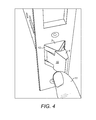
Fig. 4 is an isometric view of the assembly showing the latchbolt being manually transformed from the first condition towards a second condition. - Referring first to
Fig. 1 , the latchbolt generally comprises a rear part 1 and a head assembly 2 comprising afirst part 3 fixed to the rear part 1 and asecond part 4 pivotally mounted on thefirst part 3 by a pin 5. The pin 5 passes through a pair of apertures in thepart 3 and passageways 7 in a pair of lugs on thepart 4. Atorsion spring 8 is carried on the pin 5 and spring biases thepart 4 to the orientation shown inFig. 3 . - A
compression spring 9, schematically shown inFig. 1 , biases the latchbolt outwardly (to the left as seen inFig. 1 ). Thespring 9 acts between a fixed part of the casing of the assembly and the rear of the latchbolt. When thepart 4 of the head of the latchbolt is in the orientation shown inFig. 3 , the head assembly 2 is in its first condition and the latchbolt operates in the manner of a conventional chamfered latch and indeed, as can be seen inFig. 3 , the shape of the latchbolt is that of a conventional chamfered latch. Thus if a force is applied in the direction of the arrow I inFig. 3 , the latchbolt is moved inwardly into the casing. - When a door, in which the latch assembly is mounted, is in a closed position, the latchbolt is housed within a keeper. If pressure is now applied to open the door, the head assembly is brought into contact with the keeper and sideways force is applied to a
flat face 10 of thepart 4 of the head assembly. Arrow II inFig. 3 shows the direction of this force. That sideways force is mimicked inFig. 4 where afinger 11 is shown applying the force. With sufficient sideways force, the resilient bias of thetorsion spring 8 is overcome and thepart 4 pivots on the pin 5, as shown inFig. 4 . InFig. 4 thepart 4 is shown pivoted only partway to its other position but it will be understood that, when fully pivoted, it provides an inclined plane comprising theflat face 10 on thepart 4 and faces 12 on thepart 3. This is the second condition of the head assembly 2, in which thefaces spring 9. - As shown in
Figs. 2 to 4 , the casing is preferably also provided with a locking bolt opening for receiving a locking bolt (not shown). The locking bolt is operated by a key and when the locking bolt is in an extended position in a keeper, the bolt retains the door in a closed position. - It will be noted that the force required to open the door when it is latched closed is determined partly by the stiffness of the
torsion spring 8 and can be set to a greater force than the force required to move the latchbolt inwardly as the door is closed. - The invention may be applied to a wide variety of applications, not necessarily limited to doors. It may be of particular advantage for a door of a prison cell since it removes the need to provide a handle on the inside of the door for the purpose of operating the latchbolt.
- The latchbolt described above may be supplied as part of a latch assembly or may be retrofitted to an existing latch assembly.
- Where in the foregoing description, integers or elements are mentioned which have known, obvious or foreseeable equivalents, then such equivalents are herein incorporated as if individually set forth. Reference should be made to the claims for determining the true scope of the present invention, which should be construed so as to encompass any such equivalents. It will also be appreciated by the reader that integers or features of the invention that are described as preferable, advantageous, convenient or the like are optional and do not limit the scope of the independent claims.
Claims (14)
- A latch assembly comprising a casing and a latchbolt mounted in the casing, the latchbolt including a head assembly movable between an extended position in which the head assembly projects out of the casing through an opening in the casing, and a retracted position in which the head assembly is contained at least substantially within the casing, the head assembly being biased toward the extended position, wherein
the head assembly of the latchbolt is biased into a first condition in which it is able to operate as a conventional chamfered latchbolt, the head assembly being cammed from the extended position into the retracted position when a first side of the latchbolt head assembly is subjected to a lateral force in a first direction and the head assembly being resistant to being cammed from the extended position into the retracted position when a second side of the latchbolt head assembly, opposite to the first side, is subjected to a lateral force in a second direction opposite to the first direction, and
the head assembly of the latchbolt is able to be transformed against the bias into a second condition in which the head assembly is cammed from the extended position into the retracted position when the second side of the latchbolt head assembly is subjected to the lateral force in the second direction. - A latch assembly according to claim 1, in which a lateral force applied to the head assembly in the second direction is effective to transform the head assembly of the latchbolt from the first condition to the second condition.
- A latch assembly according to claim 1 or 2, in which the head assembly has a shape corresponding substantially to a latch head chamfered on one side in the first condition and a shape corresponding substantially to a latch head chamfered on its opposite side in the second condition.
- A latch assembly according to any preceding claim, in which the head assembly comprises a first part providing the cam surface on the first side of the assembly and capable of receiving the lateral force in the first direction to cam the head assembly from the extended position into the retracted position, and a second part providing the cam surface on the second side of the assembly and capable of receiving the lateral force in the second direction opposite to the first direction, the second part being movably mounted on the first part.
- A latch assembly according to claim 4, in which the head assembly further comprises a spring biasing the second part into a position corresponding to the first condition of the head assembly.
- A latch assembly according to claim 4 or 5, in which the second part is pivotally mounted on the first part for pivotal movement about an axis transverse to the direction of movement of the head assembly between the retracted and extended positions and substantially parallel to said first and second directions.
- A latch assembly according to claim 5 and 6, in which the spring is a torsion spring.
- A latch assembly comprising a casing and a latchbolt mounted in the casing, the latchbolt including a head assembly movable between an extended position in which the head assembly projects out of the casing through an opening in the casing, and a retracted position in which the head assembly is contained at least substantially within the casing, the head assembly being biased toward the extended position, wherein the head assembly of the latchbolt is biased into a first condition in which it has a shape corresponding substantially to a latch head chamfered on one side, and is able to be transformed against the bias into a second condition in which it has a shape corresponding substantially to a latch head chamfered on its opposite side.
- A latch assembly according to any preceding claim, in which the latchbolt is resiliently biased towards the extended position by a spring.
- A latch assembly according to claim 9, in which the spring is a compression spring.
- A latch assembly according to any preceding claim, further comprising a locking bolt movable between an extended position in which a head of the locking bolt projects out of the casing through an opening in the casing, and a retracted position in which the head of the bolt is contained at least substantially within the casing.
- A latch assembly according to claim 11, in which movement of the locking bolt is effected by a manually operable key.
- A latch assembly according to claim 11 or 12, in which the latch assembly is a mortise lock assembly.
- A latchbolt comprising a head assembly according to any preceding claim.
Applications Claiming Priority (1)
| Application Number | Priority Date | Filing Date | Title |
|---|---|---|---|
| GB1202968.2A GB2499605A (en) | 2012-02-21 | 2012-02-21 | Latch assembly and latchbolt |
Publications (1)
| Publication Number | Publication Date |
|---|---|
| EP2631399A2 true EP2631399A2 (en) | 2013-08-28 |
Family
ID=45939949
Family Applications (1)
| Application Number | Title | Priority Date | Filing Date |
|---|---|---|---|
| EP13155307.5A Withdrawn EP2631399A2 (en) | 2012-02-21 | 2013-02-14 | Latch assembly and latchbolt |
Country Status (2)
| Country | Link |
|---|---|
| EP (1) | EP2631399A2 (en) |
| GB (1) | GB2499605A (en) |
Cited By (1)
| Publication number | Priority date | Publication date | Assignee | Title |
|---|---|---|---|---|
| CN109898928A (en) * | 2017-12-11 | 2019-06-18 | 上海英还实业有限公司 | Integral type latch bolt mechanism and its door lock |
Families Citing this family (1)
| Publication number | Priority date | Publication date | Assignee | Title |
|---|---|---|---|---|
| CN104948008B (en) * | 2015-07-24 | 2017-10-13 | 广西平果力保佳锁业有限责任公司 | A kind of central controlled lock lock body |
Family Cites Families (4)
| Publication number | Priority date | Publication date | Assignee | Title |
|---|---|---|---|---|
| US4135746A (en) * | 1977-02-17 | 1979-01-23 | Sterling John G | Latch bolt assembly |
| US4573333A (en) * | 1983-08-19 | 1986-03-04 | Choi Yoon H | Electrical door lock |
| NL1034174C2 (en) * | 2007-07-23 | 2009-01-27 | Nemef B V | Lap housing with a lap and a lap module. |
| SE531998C2 (en) * | 2008-02-01 | 2009-09-22 | Assa Ab | Lock with plunger |
-
2012
- 2012-02-21 GB GB1202968.2A patent/GB2499605A/en not_active Withdrawn
-
2013
- 2013-02-14 EP EP13155307.5A patent/EP2631399A2/en not_active Withdrawn
Cited By (1)
| Publication number | Priority date | Publication date | Assignee | Title |
|---|---|---|---|---|
| CN109898928A (en) * | 2017-12-11 | 2019-06-18 | 上海英还实业有限公司 | Integral type latch bolt mechanism and its door lock |
Also Published As
| Publication number | Publication date |
|---|---|
| GB2499605A (en) | 2013-08-28 |
| GB201202968D0 (en) | 2012-04-04 |
Similar Documents
| Publication | Publication Date | Title |
|---|---|---|
| JP6475797B2 (en) | Locking device | |
| CN101529034B (en) | Multipoint door lock | |
| CN1301362C (en) | Electromagnetic lock device | |
| US11408207B2 (en) | Lock with a long-travel deadbolt | |
| KR101467285B1 (en) | Locking assembly for latch bolt | |
| KR101428686B1 (en) | Locking handle device for sliding type fittings | |
| GB2499605A (en) | Latch assembly and latchbolt | |
| US11384569B2 (en) | Lock with replaceable modules | |
| KR20150063404A (en) | Anti-friction latchbolt | |
| CN212027443U (en) | Oblique tongue anti-insertion and anti-theft opening structure and door lock with same | |
| US11124993B2 (en) | Lock with emergency unlocking feature | |
| KR20130080629A (en) | Mortise for door-lock system | |
| CN115142742B (en) | Zipper lock and suitcase | |
| KR101890318B1 (en) | Assembly for swing type latch bolt | |
| KR20140126580A (en) | Edge bolt assembly for mortise of door lock | |
| KR101467284B1 (en) | Actuator for latch-bolt locking assembly | |
| KR200479071Y1 (en) | Locking device for sliding door | |
| KR102076163B1 (en) | Lockless handle assembly with grip type | |
| US20210164262A1 (en) | Lock | |
| KR20150027871A (en) | Locking handle device for sliding type fittings | |
| KR101481324B1 (en) | Door Lock Provided with a Dead Bolt | |
| CN108027195B (en) | Handle and freezer | |
| CN206636372U (en) | A kind of safety door latch component | |
| US20250003268A1 (en) | Latchbolt mechanism and latchbolt accommodating mechanism | |
| JP6366917B2 (en) | Flat latch handle |
Legal Events
| Date | Code | Title | Description |
|---|---|---|---|
| PUAI | Public reference made under article 153(3) epc to a published international application that has entered the european phase |
Free format text: ORIGINAL CODE: 0009012 |
|
| AK | Designated contracting states |
Kind code of ref document: A2 Designated state(s): AL AT BE BG CH CY CZ DE DK EE ES FI FR GB GR HR HU IE IS IT LI LT LU LV MC MK MT NL NO PL PT RO RS SE SI SK SM TR |
|
| AX | Request for extension of the european patent |
Extension state: BA ME |
|
| STAA | Information on the status of an ep patent application or granted ep patent |
Free format text: STATUS: THE APPLICATION IS DEEMED TO BE WITHDRAWN |
|
| 18D | Application deemed to be withdrawn |
Effective date: 20150901 |