EP2631322B1 - Alloy-coated boiler component - Google Patents
Alloy-coated boiler component Download PDFInfo
- Publication number
- EP2631322B1 EP2631322B1 EP11834129.6A EP11834129A EP2631322B1 EP 2631322 B1 EP2631322 B1 EP 2631322B1 EP 11834129 A EP11834129 A EP 11834129A EP 2631322 B1 EP2631322 B1 EP 2631322B1
- Authority
- EP
- European Patent Office
- Prior art keywords
- alloy
- mass
- end region
- coating
- region
- Prior art date
- Legal status (The legal status is an assumption and is not a legal conclusion. Google has not performed a legal analysis and makes no representation as to the accuracy of the status listed.)
- Not-in-force
Links
Images


Classifications
-
- B—PERFORMING OPERATIONS; TRANSPORTING
- B23—MACHINE TOOLS; METAL-WORKING NOT OTHERWISE PROVIDED FOR
- B23K—SOLDERING OR UNSOLDERING; WELDING; CLADDING OR PLATING BY SOLDERING OR WELDING; CUTTING BY APPLYING HEAT LOCALLY, e.g. FLAME CUTTING; WORKING BY LASER BEAM
- B23K35/00—Rods, electrodes, materials, or media, for use in soldering, welding, or cutting
- B23K35/22—Rods, electrodes, materials, or media, for use in soldering, welding, or cutting characterised by the composition or nature of the material
- B23K35/36—Selection of non-metallic compositions, e.g. coatings or fluxes; Selection of soldering or welding materials, conjoint with selection of non-metallic compositions, both selections being of interest
-
- B—PERFORMING OPERATIONS; TRANSPORTING
- B23—MACHINE TOOLS; METAL-WORKING NOT OTHERWISE PROVIDED FOR
- B23K—SOLDERING OR UNSOLDERING; WELDING; CLADDING OR PLATING BY SOLDERING OR WELDING; CUTTING BY APPLYING HEAT LOCALLY, e.g. FLAME CUTTING; WORKING BY LASER BEAM
- B23K35/00—Rods, electrodes, materials, or media, for use in soldering, welding, or cutting
- B23K35/22—Rods, electrodes, materials, or media, for use in soldering, welding, or cutting characterised by the composition or nature of the material
- B23K35/24—Selection of soldering or welding materials proper
- B23K35/30—Selection of soldering or welding materials proper with the principal constituent melting at less than 1550°C
-
- B—PERFORMING OPERATIONS; TRANSPORTING
- B23—MACHINE TOOLS; METAL-WORKING NOT OTHERWISE PROVIDED FOR
- B23K—SOLDERING OR UNSOLDERING; WELDING; CLADDING OR PLATING BY SOLDERING OR WELDING; CUTTING BY APPLYING HEAT LOCALLY, e.g. FLAME CUTTING; WORKING BY LASER BEAM
- B23K35/00—Rods, electrodes, materials, or media, for use in soldering, welding, or cutting
- B23K35/22—Rods, electrodes, materials, or media, for use in soldering, welding, or cutting characterised by the composition or nature of the material
- B23K35/24—Selection of soldering or welding materials proper
- B23K35/30—Selection of soldering or welding materials proper with the principal constituent melting at less than 1550°C
- B23K35/3033—Ni as the principal constituent
- B23K35/304—Ni as the principal constituent with Cr as the next major constituent
-
- B—PERFORMING OPERATIONS; TRANSPORTING
- B23—MACHINE TOOLS; METAL-WORKING NOT OTHERWISE PROVIDED FOR
- B23K—SOLDERING OR UNSOLDERING; WELDING; CLADDING OR PLATING BY SOLDERING OR WELDING; CUTTING BY APPLYING HEAT LOCALLY, e.g. FLAME CUTTING; WORKING BY LASER BEAM
- B23K9/00—Arc welding or cutting
- B23K9/02—Seam welding; Backing means; Inserts
- B23K9/028—Seam welding; Backing means; Inserts for curved planar seams
- B23K9/0282—Seam welding; Backing means; Inserts for curved planar seams for welding tube sections
-
- C—CHEMISTRY; METALLURGY
- C22—METALLURGY; FERROUS OR NON-FERROUS ALLOYS; TREATMENT OF ALLOYS OR NON-FERROUS METALS
- C22C—ALLOYS
- C22C19/00—Alloys based on nickel or cobalt
- C22C19/03—Alloys based on nickel or cobalt based on nickel
- C22C19/05—Alloys based on nickel or cobalt based on nickel with chromium
-
- C—CHEMISTRY; METALLURGY
- C22—METALLURGY; FERROUS OR NON-FERROUS ALLOYS; TREATMENT OF ALLOYS OR NON-FERROUS METALS
- C22C—ALLOYS
- C22C19/00—Alloys based on nickel or cobalt
- C22C19/03—Alloys based on nickel or cobalt based on nickel
- C22C19/05—Alloys based on nickel or cobalt based on nickel with chromium
- C22C19/058—Alloys based on nickel or cobalt based on nickel with chromium without Mo and W
-
- C—CHEMISTRY; METALLURGY
- C23—COATING METALLIC MATERIAL; COATING MATERIAL WITH METALLIC MATERIAL; CHEMICAL SURFACE TREATMENT; DIFFUSION TREATMENT OF METALLIC MATERIAL; COATING BY VACUUM EVAPORATION, BY SPUTTERING, BY ION IMPLANTATION OR BY CHEMICAL VAPOUR DEPOSITION, IN GENERAL; INHIBITING CORROSION OF METALLIC MATERIAL OR INCRUSTATION IN GENERAL
- C23C—COATING METALLIC MATERIAL; COATING MATERIAL WITH METALLIC MATERIAL; SURFACE TREATMENT OF METALLIC MATERIAL BY DIFFUSION INTO THE SURFACE, BY CHEMICAL CONVERSION OR SUBSTITUTION; COATING BY VACUUM EVAPORATION, BY SPUTTERING, BY ION IMPLANTATION OR BY CHEMICAL VAPOUR DEPOSITION, IN GENERAL
- C23C4/00—Coating by spraying the coating material in the molten state, e.g. by flame, plasma or electric discharge
- C23C4/04—Coating by spraying the coating material in the molten state, e.g. by flame, plasma or electric discharge characterised by the coating material
- C23C4/06—Metallic material
- C23C4/067—Metallic material containing free particles of non-metal elements, e.g. carbon, silicon, boron, phosphorus or arsenic
-
- F—MECHANICAL ENGINEERING; LIGHTING; HEATING; WEAPONS; BLASTING
- F22—STEAM GENERATION
- F22B—METHODS OF STEAM GENERATION; STEAM BOILERS
- F22B37/00—Component parts or details of steam boilers
- F22B37/02—Component parts or details of steam boilers applicable to more than one kind or type of steam boiler
- F22B37/04—Component parts or details of steam boilers applicable to more than one kind or type of steam boiler and characterised by material, e.g. use of special steel alloy
-
- B—PERFORMING OPERATIONS; TRANSPORTING
- B23—MACHINE TOOLS; METAL-WORKING NOT OTHERWISE PROVIDED FOR
- B23K—SOLDERING OR UNSOLDERING; WELDING; CLADDING OR PLATING BY SOLDERING OR WELDING; CUTTING BY APPLYING HEAT LOCALLY, e.g. FLAME CUTTING; WORKING BY LASER BEAM
- B23K2101/00—Articles made by soldering, welding or cutting
- B23K2101/04—Tubular or hollow articles
- B23K2101/06—Tubes
Definitions
- the present invention relates to a boiler component (hereinafter, referred to as "boiler tube”) such as a tube component constituting a heat transfer tube in various types of boilers, or a plate material-tube material composite panel (hereinafter, referred to as “boiler furnace panel”) constituting a furnace housing with a cooling-water passage, and more specifically to a boiler component with alloy coatings for improving durability and suitable for the welding.
- a boiler tube such as a tube component constituting a heat transfer tube in various types of boilers, or a plate material-tube material composite panel (hereinafter, referred to as “boiler furnace panel”) constituting a furnace housing with a cooling-water passage, and more specifically to a boiler component with alloy coatings for improving durability and suitable for the welding.
- boilers recovering and utilizing refuse incineration heat have increased, whereby, particularly, a problem of erosion (wear) is caused by combustion ash dust, and in order to solve this problem, boilers with a specification applying a thermal spray coating with alloy superior in erosion resistance are starting to be commonly used.
- the above described alloy coating is a coating (unmelted coating) which is left as thermal-sprayed by, for example, HVOF (High Velocity Oxygen Fuel) or plasma thermal spraying apparatus and a self-fluxing alloy coating having fusing treatment applied after being thermal sprayed is rarely used.
- HVOF High Velocity Oxygen Fuel
- a constitution applying a melted coating with a self-fluxing alloy to a boiler tube is disclosed. It adopts the constitution in which a portion of about 50 mm at an end of the boiler tube is not thermally sprayed, and this portion is used as a margin for joining (the patent document 1, page 3, column 4, lines 15 to 16). On this portion which is not thermally sprayed, process for fitting a protector member is performed instead of coating after welding (the same document, column 4, lines 24 to 26). Since above process requires a special order of the protector member (for example, made of alumina) having high erosion resistance, or a fitting operation inside a narrow boiler, it results in higher cost in materials and working and also requires front loaded procurement of materials.
- the protector member for example, made of alumina
- an alloy-coated boiler component (a boiler tube and a boiler furnace panel) in which the melted coating with the alloy material superior in erosion resistance and corrosion resistance is applied to the whole area of the metallic base material to be protected and thermal shock cracking does not occur on the melted coating even if the local temperature rises rapidly at the time of the welding operation
- the present applicant proposes an alloy-coated boiler component in which a coating with a Ni-Cr alloy material in which the contents of B (boron) and Si (silicon) which are melting point lowering elements are low (the proportion of B is not more than 0.1 mass % and the proportion of Si is not more than 0.5 mass %) is applied to an end region (a rapidly-rising temperature region where thermal shock cracking is likely to occur at the time of the welding operation) including an end to be welded, and a coating with a Ni-Cr alloy material including 1 to 5 mass % of B and Si respectively is applied to a region other than the end region (a remaining region other than the rapidly-rising temperature region) (see the patent document 4
- the alloy-coated boiler component described in the patent document 4 has the coating with the Ni-Cr alloy material on the whole area of the metallic base material to be protected, it has good durability and corrosion resistance. Further, the coating applied to the end region (the rapidly-rising temperature region where thermal shock cracking is likely to occur at the time of the welding operation) has improved thermal shock resistance because the contents of B and Si are low. Accordingly, thermal shock cracking does not occur on the coating even if the local temperature rises rapidly at the time of the welding operation (superior in thermal shock resistance).
- the coating with the Ni-Cr alloy material comprising less contents of B and Si applied to the end region is low in hardness (to inhibit high hardness precipitate from being produced by the reaction by B or Si with Cr), it has resistance characteristics (resistance to shock) not only to thermal shock but also to mechanical shock.
- the alloy material for obtaining the melted coating applied to the end region comprises less contents of B and Si which are melting point lowering elements (the content of B is not more than 0.1 mass % and the content of Si is not more than 0.5 mass %), its melting point is over 1500°C, which is far higher compared to the melting point of the alloy material (the contents of B and Si are 1 to 5 mass % respectively) for obtaining melted coating applied to the region other than the end region.
- the end region (the rapidly-rising temperature region)
- the coating in the end region should be performed by weld surfacing.
- the temperature in the metallic base material rises up to about 1500°C, there is a fear that distortion (welding distortion) might occur in the metallic base material.
- an alloy-coated boiler component in which the coatings in all regions including the end region can be formed by thermal spraying-fusing treatment and further it is good in thermal shock resistance and resistance to shock in the coating formed on the end region.
- An object of the present invention is to provide an alloy-coated boiler component in which the whole area (the end region and the non-end region) of the metallic base material to be protected has melted coatings which are formed by thermal spraying-fusing treatment and the melted coating formed on the end region is superior in thermal shock resistance and resistance to shock.
- the alloy-coated boiler component of the present invention has melted coatings with the self-fluxing alloys which can be formed by thermal spraying-fusing treatment on the whole area including the end region of the metallic base material to be protected, it is possible to manufacture it with high efficiency. Further, since it is not necessary to perform weld surfacing for forming the coating, there is no fear that welding distortion would occur in the metallic base material when manufacturing. Further, since the melted coating formed on the end region has good thermal shock resistance and resistance to shock, thermal shock cracking hardly occurs even if the local temperature rises rapidly at the time of the welding operation and cracking hardly occurs against mechanical shock. Further, the alloy-coated boiler component of the present invention is also superior in durability and corrosion resistance.
- the boiler component of the present invention is an alloy-coated boiler component in which a coating (coat) with an alloy material of which main constituent is Ni-Cr is applied to a metallic base material and an end is welded.
- the alloy material (self-fluxing alloy) constituting the coating in an end region of the metallic base material is different from that in a non-end region of the metallic base material.
- the end region is a region including the end (welding portion) and the proximity of the end, where the temperature rises rapidly in association with welding the end.
- the range of the end region differs according to a shape of the metallic base material (a form of the boiler component) or the like.
- the end region can be a region between the end and a location spaced 15 to 500mm from this end.
- the end region can be (1) a region between the end of the tube material and a location spaced 15 to 500mm from this end, (2) a region between the end of the plate material and a location spaced 15 to 500mm from this end, and (3) regions including the plate materials located on both sides (which may include a part of the tube materials welded to each of the plate materials located on both sides).
- the non-end region is a region other than the end region in the metallic base material to be protected.
- the melted coating with the first alloy material comprising not less than 1.5 mass % and not more than 2.5 mass % of B (boron), not less than 3.5 mass % and not more than 4.0 mass % of Si (silicon), not more than 0.4 mass % of C (carbon) , and not less than 12.0 mass % and not more than 17.0 mass % of Cr (chromium), and the balance being Ni (nickel) and incidental impurities is applied to the end region of the metallic base material.
- the first alloy material is a Ni-Cr self-fluxing alloy comprising not less than 1.5 mass % of B and not less than 3.5 mass % of Si.
- the melting point of the first alloy material is, for example, between 1050 and 1100 °C, and since such an alloy as having a melting point of this level can avoid distortion in the metallic base material in association with fusing treatment of a thermal spray coat, it is possible to apple a coating by thermal spraying-fusing treatment.
- the melted coatings can be formed by thermal spraying-fusing treatment on the whole area including the end region of the metallic base material to be protected, it is possible to manufacture alloy-coated boiler components with high efficiency.
- the proportion of B is not more than 2.5 mass %
- the proportion of Si is not more than 4.0 mass %, and they are small amounts (the contents of B and Si are low to some extent) compared to the contents of B and Si of a second alloy material to be hereinafter described
- the melted coating formed with the first alloy material has good thermal shock resistance. Accordingly, thermal shock cracking hardly occurs on the melted coating with the first alloy material applied to the end region even if the local temperature rises rapidly at the time of the welding operation.
- the hardness of the melted coating is sufficiently low (for example, HV ⁇ 400) and resistance to shock improves so that even if subjected to mechanical shock when the boiler component is welded or attached, cracking hardly occurs on this melted coating.
- the proportion of B in the first alloy material is not less than 1.5 mass % and not more than 2.5 mass %, and preferably not less than 1.8 mass % and not more than 2.4 mass %. Since if the proportion of B is less than 1.5 mass %, the melting point of the resultant alloy material cannot be lowered sufficiently, distortion occurs in the metallic base material when the thermal spray coat with this alloy material is to be remelted, it is not possible to apply a coating utilizing this alloy material by thermal spraying-fusing treatment. On the other hand, with the alloy material comprising more than 2.5 mass % of B, it is difficult to form a melted coating with good thermal shock resistance and resistance to shock on the end region.
- the proportion of Si in the first alloy material is not less than 3.5 mass % and not more than 4.0 mass %, and preferably not less than 3.6 mass % and not more than 4.0 mass %. Since if the proportion of Si is less than 3.5 mass % the melting point of the resultant alloy material cannot be lowered sufficiently, distortion occurs in the metallic base material when the thermal spray coat with this alloy material is to be remelted, it is not possible to apply a coating utilizing this alloy material by thermal spraying-fusing treatment. On the other hand, with the alloy material comprising more than 4.0 mass % of Si, it is difficult to form a melted coating with good thermal shock resistance and resistance to shock on the end region.
- the proportion of C in the first alloy material is not more than 0.4 mass %, and preferably not more than 0.2 mass %.
- the alloy material comprising more than 0.4 mass % of C, it is difficult to form a melted coating with good resistance to shock and having a low hardness on the end region.
- the first alloy material includes Cr in a specific proportion, a melted coating formed on the end region is superior in corrosion resistance.
- the proportion of Cr in the first alloy material is not less than 12.0 mass % and not more than 17.0 mass %, and preferably not less than 14.5 mass % and not more than 16.5 mass %.
- the melted coating with the second alloy material comprising more than 2.5 mass % and not more than 4.0 mass % of B, more than 4.0 mass % and not more than 5.0 mass % of Si, not less than 0.5 mass % and not more than 0.9 mass % of C, and not less than 12.0 mass % and not more than 17.0 mass % of Cr, and the balance being Ni and incidental impurities is applied to the non end region of the metallic base material.
- the second alloy material is a Ni-Cr self-fluxing alloy comprising more than 2.5 mass % and not more than 4.0 mass % of B and more than 4.0 mass % and not more than 5.0 mass % of Si.
- the melting point of the second alloy material is, for example, between 1000 and 1050 C, and since the alloy has such a low melting point as this, thermal spraying-fusing treatment can be performed efficiently.
- the second alloy material comprises more than 2.5 mass % of B and more than 4.0 mass % of Si, the melted coating formed with this second alloy material is inferior in thermal shock resistance compared to that formed with the first alloy material.
- the second alloy material comprises some high proportions of B, Si and C
- HV hardness
- the non-end region where the melted coating with the second alloy material is applied to is hardly subjected to mechanical shock even when the boiler component is welded or attached, cracking hardly occurs.
- the proportion of B in the second alloy material is more than 2.5 mass % and not more than 4.0 mass %. If the proportion of B is not more than 2.5 mass %, thermal spraying-fusing treatment cannot be performed efficiently. On the other hand, the alloy material comprising more than 4.0 mass % of B will lead to lowering of thermal shock resistance and resistance to shock in the melted coating formed on the non-end region.
- the proportion of Si in the second alloy material is more than 4.0 mass % and not more than 5.0 mass %. If the proportion of Si is not more than 4.0 mass %, thermal spraying-fusing treatment cannot be performed efficiently. On the other hand, the alloy material comprising more than 5.0 mass % of Si will lead to lowering of thermal shock resistance and resistance to shock in the melted coating formed on the non-end region.
- the proportion of C in the second alloy material is not less than 0.5 mass % and not more than 0.9 mass %.
- the second alloy material comprises Cr in a specific proportion, a melted coating formed on the non-end region is superior in corrosion resistance.
- the proportion of Cr in the second alloy material is not less than 12.0 mass % and not more than 17.0 mass %.
- Preferred second alloy materials include a nickel self-fluxing alloy material having composition defined in JIS H 8303 and a nickel self-fluxing alloy material having composition defined in ISO 14920.
- the boiler furnace panel 10 (alloy-coated boiler component of the present invention) shown in FIG. 1A and FIG. 1B is one in which a coating with the first alloy material (hereinafter referred to as “first alloy coating”) 15 and a coating with the second alloy material (hereinafter referred to as “second alloy coating”) 16 are formed to a steel panel 11 (metallic base material) by thermal spraying-fusing treatment at a factory previously, and when assembling a furnace housing, neighboring ends are welded each other while joining a plurality of panels.
- first alloy coating first alloy material
- second alloy coating second alloy coating
- a steel panel 11 (plate material - tube material composite panel) is constituted such that, in order to form a base unit for a furnace housing with a cooling water passage, a tube portion 12 (tube material) forming a cooling water passage and a plate portion 13 (plate material) forming a joint portion are arranged alternately and joined tightly with welding or the like and further, for erosion resistance and corrosion resistance, at one side (a portion to be protected) to be a furnace inner wall, a melted coating with the alloy material (the first alloy material or the second alloy material) is formed on the whole area except for portions to be welded.
- the melted coatings are separates into the first alloy coating 15 on the end region and the second alloy coating 16 on the non-end region.
- the end region applied with the first alloy coating 15 can be set as follows:
- width C1 of the end region in the tube portion 12 and the width C2 of the end region in the plate portion 13 may be the same size.
- a thin notch 14 with a width of about 0.5 to 2 mm is formed. It is to secure a deflection margin for welding to align the tube portion 12.
- a large bevel (chamfer) or taper is also provided to become a welding groove.
- the first alloy material constituting the first alloy coating 15 has Ni-Cr as a main constituent and comprises B and Si which are melting point lowering elements in a certain proportion, it has a self-fluxing property, however, the proportions of B and Si are low such that B is not more than 2.5 mass % and Si is not more than 4.0 mass % so that cracking would not occur owing to thermal shock at the time of the welding operation and various mechanical shocks.
- a thickness of the first alloy coating 15 is between 0.3 and 3.0 mm and preferably between about 1.0 and 2.0 mm.
- the second alloy material constituting the second alloy coating 16 has Ni-Cr as a main constituent and comprises more than 2.5 mass % and not more than 4.0 mass % of B and more than 4.0 mass % and not more than 5.0 mass % of Si in order to be applied efficiently by thermal spraying process and fusing treatment.
- a thickness of the second alloy coating 16 is between 0.3 and 3.0 mm and preferably between about 1.0 and 2.0 mm.
- the boiler furnace panel 10 can be manufactured such that the first alloy coating 15 is formed on one side of the end region of the steel panel 11 (metallic base material) which are the plate portions 13 and the tube portions 12 are joined alternately, in accordance with this, the second alloy coating 16 is formed on one side of the non-end region, and further, the end shape is finished.
- the steel panel 11 is made by joining the tube portions 12 and the plate portions 13 consisting of steel materials alternately by welding or the like, and the plate portions 13 are located on both sides.
- a length (L) is between about 1000 and 9000 mm
- a width (W) is between about 300 and 500 mm
- a diameter of the tube portion 12 is between about 30 and 80 mm
- a thickness of the tube portion 12 is between about 5.0 and 7.0 mm
- a thickness of the plate portion 13 is about 3 and 9 mm.
- the first alloy coating 15 is formed on one side of the end region of the steel panel 11. Further, about 50 to 150 mm of the tip portion sometimes remains without having coating process for fixation, holding, etc. during the operation, however, in that case, it is cut off at the time of finishing the end shape.
- a width (indicated as C1' in FIG. 3 (a) ) of a region forming the first alloy coating 15 in the tube portion 12 is wider than the width (indicated as C1 in FIG. 1 ) of the end region in order to secure an overlapping (lap) portion with the second alloy coating.
- a width (indicated as C3' in FIG. 3 (a) ) of a region forming the first alloy coating 15 in the plate portions 13 located on both sides of the panel is equal to the width of the end region indicated as C3 in FIG. 1 , however, it is possible to further widen the width of the region forming the first alloy coating 15, that is to say, to form the first alloy coating 15 to a part of the tube portion 12 joined to the plate portions 13 located on both sides of the panel.
- the first alloy coating 15 is formed by thermal spraying-fusing treatment.
- thermal spraying-fusing treatment conventional known process can be adopted. Specifically, thermal spraying process of the first alloy material on the end region and fusing treatment of the thermal spray coat with the first alloy material are performed. Further, surface cleaning process such as shot blasting or the like can be performed on a processed surface (one side of the end region), if needed.
- the thermal spray coat formed by thermal spraying-fusing treatment with the first alloy material is remelted at the temperature of about 1050 to 1100°C to be a tight melted coating (the first alloy coating 15).
- the second alloy coating 16 is formed on one side of the non-end region of the steel panel 11.
- the second alloy coating 16 is formed by thermal spraying-fusing treatment in the same way as the first alloy coating 15.
- thermal spraying-fusing treatment conventional known process can be adopted. Specifically, masking of the first alloy coating 15, thermal spraying process of the second alloy material on the non-end region and then fusing treatment of the thermal spray coat with the second alloy material are performed. Further, surface cleaning process such as shot blasting or the like can be performed on a processed surface (one side of the non-end region), if needed.
- the thermal spray coat formed by thermal spraying-fusing treatment with the second alloy material is remelted at the temperature of about 1000 to 1050°C to be a tight melted coating (the second alloy coating 16).
- preferable methods for forming the first alloy coating 15 and the second alloy coating 16 include a method in which thermal spraying process with the first alloy material is performed on the end region, thermal spraying process with the second alloy material is performed on the non-end region and then fusing treatment of the thermal spray coats formed on the end region and the non-end region is performed. Further, in fusing treatment of the thermal spray coats, temperature is controlled so that the process temperature (about 1050 to 1100 ° C) for the thermal spray coat with the first alloy coating 15 and the process temperature (about 1000 to 1050°C) for the thermal spray coat with the second alloy coating 16 is switched appropriately.
- Masking of the first alloy coating 15 is performed, for example, by utilizing shielding plates such as sheet metal or the like, or heat-resistant masking tapes. Further, masking is performed such that a part of the first alloy coating 15 and a part of the second alloy coating 16 are overlapping in order not to expose a base material in a clearance between the first alloy coating 15 and the second alloy coating 16. In such an overlapping portion, it is better to provide a taper in thickness of both coatings so that a steep step would not appear.
- Thermal spraying process and fusing treatment for forming the first alloy coating 15 and the second alloy coating 16 are performed by a common technique utilizing a known device. That is, the thermal spraying of the first alloy material and the second alloy material which are self-fluxing alloys can be performed efficiently by a common technique utilizing a known device. Further, basically, fusing treatment also can be performed efficiently utilizing a known high-frequency induction heater by a common moving heating method (for example, as shown in FIGs. 4 (c) and (e) , a method for moving an induction coil 40).
- an uncoated portion at a tip of the steel panel 11 is cut off as shown in FIG. 5 . This is performed by the plasma cutting or the like and at the same time or another time, a notch 14 is formed. Further, in preparation for welding another boiler furnace panel 10, a tip of the tube portion 12 is beveled (chamfered). Thus, when terminating the finishing of the ends, one of the boiler furnace panels 10 is completed. Further, similarly, the boiler furnace panels 10 are efficiently manufactured one after another, and then they are stacked to be kept in a factory, warehouse and so on.
- the welding steps comprise positioning (aligning) steps, tube end welding steps and plate portion welding steps, and in that order, a treatment of each step is applied to a welding portion 20 of a pair of boiler furnace panels 10 to be joined.
- both boiler furnace panels 10 are fixed in a state in which the tips of tube portions 12 to become the welding portions 20 face each other. Then, if there is a position gap in a state in which tube ends face each other and the position gap is slight resulting from the time of manufacturing the boiler furnace panel 10 (the time of forming the first alloy coating 15 and the second alloy coating 16) or the like, the positions of the faced tube end are aligned by driving a small wedge into the notch 14, or the like.
- the annular welding is performed from a tube inner surface side to a tube outer surface side for several times separately in order not to generate any voids or the like and in order not to overheat.
- a filler metal (a filler metal used for forming super alloy welding layers 23, 24 and 25) used in these tube end welding steps, an alloy material of which main constituent is Ni-Cr including not more than 0.1 mass % of B and not more than 0.5 mass % of Si is preferable.
- a welding layer (corresponding to the welding layer 21) facing the hollow of the tube and a welding layer (corresponding to the welding layer 22) buried in the tube wall can be formed with carbon steel (for example, a filler rod of 50kg/mm 2 class), and accordingly, costs can be reduced.
- the first alloy coating 15 formed on the end region of the boiler furnace panel 10 comprises less of B and Si and is superior in thermal shock resistance (having no sensitivity in thermal shock cracking) compared to the second alloy coating 16 formed on the non-end region, thermal shock cracking does not occur on the first alloy coating 15 even if the temperature rises rapidly on the end region at the time of the welding operation. Therefore, it is possible to perform the welding operation easily and appropriately without damaging the first alloy coating 15.
- the second alloy coating 16 formed on the non-end region of the boiler furnace panel 10 is inferior in thermal shock resistance (having sensitivity in thermal shock cracking) compared to the first alloy coating 15, since it is applied to the non-end region where the temperature does not rise rapidly (thermal shock is not given) even at the time of the welding operation, thermal shock cracking does not occur in the second alloy coating 16, either. Therefore, it is possible to perform the welding operation easily and appropriately without damaging the second alloy coating 16.
- a cover plate with a size for covering at least both notches 14 in the plate portions 13 to be welded is welded over the plate portions 13 of the both boiler furnace panels 10. Welding of the cover plate is performed from the other side of the steel panel 11 (that is, a surface where the first alloy coating 15 is not formed, a furnace outer wall surface or a surface which does not need protection).
- steps may be terminated by leaving an inner side of the notch 14 being the base metal as it is, that is, the steel panel 11 is exposed as it is, however, the notch 14 may be filled up in welding application utilizing the filler metal (the alloy material of which main constituent is Ni-Cr including not more than 0.1 mass % of B and not more than 0.5 mass % of Si).
- the filler metal the alloy material of which main constituent is Ni-Cr including not more than 0.1 mass % of B and not more than 0.5 mass % of Si.
- the furnace housing with cooling water passage can be constructed as shown in FIG. 1B(f) , by joining the plurality of boiler furnace panels 10 in the length direction.
- the boiler furnace panel 10 has the first alloy coating 15 superior in thermal shock resistance formed on a region including the plate portions 13 located on both sides as the end region, even in welding steps for joining boiler furnace panels 10 in the width direction, thermal shock cracking does not occur in the first alloy coating 15 formed on the end region including the plate portions 13 located on both sides.
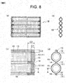
- FIG. 8 shows a boiler furnace panel (alloy-coated boiler component of the present invention) different in construction from that shown in FIG. 1A and FIG. 1B . Further, in FIG. 8 , component parts and elements identical to those of the boiler furnace panel 10 shown in FIG. 1A and FIG. 1B are denoted by identical reference numerals.
- the boiler furnace panel 18 shown in FIG. 8 has melted coatings with alloy materials (a first alloy material and a second alloy material) formed on the whole area, except portions to be welded, in one side and the other side.
- the first alloy coating 15 is formed on each of one side and the other side of the end region of the steel panel 11 (metallic base material) where the plate portions 13 and the tube portions 12 are joined alternately, and in accordance with this, the second alloy coating 16 is formed on each of one side and the other side of the non-end region.
- This boiler furnace panel 18 can be used preferably as a panel of which both sides are portions to be protected (for example, a boundary panel partitioning a first combustion room and a second combustion room) or the like.
- boiler tubes 80, 81 and 82 (the alloy-coated boiler components of the present invention) shown in FIG. 7 (a) , coatings with the alloy materials are applied to the peripheries of the tubular steel materials (metallic base materials).
- a first alloy coating 85 is formed on the periphery of each end region (a zonal region having a width indicated as C4 in the drawing), and in accordance with this, a second alloy coating 86 is formed on the periphery of each non-end region.
- the end region of the boiler tubes 80, 81 and 82 is a region where the temperature rises rapidly by welding and the width C4 of the end region is, for example, between 15 and 500 mm.
- An outer diameter of the boiler tubes 80, 81 and 82 is between about 30 and 100 mm and a length of the boiler tube 82 is between about 2000 and 10000 mm.
- the first alloy coating 85 is formed on the periphery of the end region of the tubular steel material by thermal spraying-fusing treatment utilizing the first alloy material.
- the second alloy coating 86 is formed on the periphery of the non-end region of the tubular steel material by thermal spraying-fusing treatment utilizing the second alloy material.
- the boiler tubes 80, 81 and 82 can be manufactured such that the first alloy coating 85 is formed on the periphery of the end region of the tubular steel material (metallic base materials), in accordance with this, the second alloy coating 86 is formed on the periphery of the non-end region, and further, an end shape is finished.
- Thermal spraying process and fusing treatment for forming the first alloy coating 85 and the second alloy coating 86 are performed by a common technique utilizing a known device. That is, the thermal spraying of the first alloy material and the second alloy material which are self-fluxing alloys can be performed efficiently by a common technique utilizing a known device.
- fusing treatment includes a known method in which an induction coil connected to a high-frequency induction heater is fit loosely in the end region, inductively heated, and a thermal spray coat is remelted. Further, at the same time as fusing treatment, bending work may be performed. As described above, in manufacturing steps for the boiler tubes 80, 81 and 82, since all the melted coatings (the first alloy coating 85 and the second alloy coating 86) can be formed by thermal spraying-fusing treatment, it is far superior in manufacturing efficiency compared to manufacturing steps combining with weld surfacing.
- the first alloy coating 85 formed on the end region of the boiler tubes 80, 81 and 82 comprises less of B and Si and is superior in thermal shock resistance (having no sensitivity in thermal shock cracking) compared to the second alloy coating 86 formed on the non-end region, thermal shock cracking does not occur on the first alloy coating 85 even if the temperature rises rapidly on the end region by welding. Further, the second alloy coating 86 which is inferior in thermal shock resistance (having sensitivity in thermal shock cracking) is formed on the non-end region where the temperature does not rise rapidly by welding, thermal shock cracking does not occur in the second alloy coating 86, either. Therefore, it is possible to perform the welding operation easily and appropriately without damaging the first alloy coating 85 and the second alloy coating 86.
Landscapes
- Engineering & Computer Science (AREA)
- Mechanical Engineering (AREA)
- Chemical & Material Sciences (AREA)
- Metallurgy (AREA)
- Materials Engineering (AREA)
- Organic Chemistry (AREA)
- Physics & Mathematics (AREA)
- Plasma & Fusion (AREA)
- Thermal Sciences (AREA)
- General Engineering & Computer Science (AREA)
- Chemical Kinetics & Catalysis (AREA)
- Coating By Spraying Or Casting (AREA)
Description
- The present invention relates to a boiler component (hereinafter, referred to as "boiler tube") such as a tube component constituting a heat transfer tube in various types of boilers, or a plate material-tube material composite panel (hereinafter, referred to as "boiler furnace panel") constituting a furnace housing with a cooling-water passage, and more specifically to a boiler component with alloy coatings for improving durability and suitable for the welding.
- Firstly, taking an example of a boiler tube, in the past days when the operation temperature of the boiler was lower than that in these days, and the erosion and corrosion environments inside the furnace were not so severe, the steel tube for boiler (low alloy steel tube) was commonly used as it was, taking into consideration of high temperature usability concerning mechanical characteristics. Further, although stainless tubes and further titanium tubes were also used for the application requiring corrosion resistance, they were not commonly used because of their high costs.
- In recent years, boilers recovering and utilizing refuse incineration heat have increased, whereby, particularly, a problem of erosion (wear) is caused by combustion ash dust, and in order to solve this problem, boilers with a specification applying a thermal spray coating with alloy superior in erosion resistance are starting to be commonly used.
However, the above described alloy coating is a coating (unmelted coating) which is left as thermal-sprayed by, for example, HVOF (High Velocity Oxygen Fuel) or plasma thermal spraying apparatus and a self-fluxing alloy coating having fusing treatment applied after being thermal sprayed is rarely used. - The reason why the application of the melted coating with the self-fluxing alloy (self-fluxing alloy coating having fusing treatment applied after being thermal sprayed) to the boiler tube is uncommon is that an extraordinary difficult work is required because thermal shock cracking easily occurs on the melted coating under rapid local temperature rise at the time of the welding operation when the boiler tube is welded for use, whereby, the whole tubes have to be preheated at high temperature and then high temperature tubes have to be joined by welding.
However, as for the boilers in recent years, the problems concerning not only erosion but also corrosion are becoming important together with the demand for high-temperature burning for efficiency in power generation by refuse incineration, thus melted coating application to the boiler is increasingly desired. - As one example thereof, in the
patent document 1, a constitution applying a melted coating with a self-fluxing alloy to a boiler tube is disclosed. It adopts the constitution in which a portion of about 50 mm at an end of the boiler tube is not thermally sprayed, and this portion is used as a margin for joining (thepatent document 1, page 3, column 4,lines 15 to 16). On this portion which is not thermally sprayed, process for fitting a protector member is performed instead of coating after welding (the same document, column 4,lines 24 to 26). Since above process requires a special order of the protector member (for example, made of alumina) having high erosion resistance, or a fitting operation inside a narrow boiler, it results in higher cost in materials and working and also requires front loaded procurement of materials. - Next, in case of the boiler furnace panel, since it has a composite constitution in which tube materials and plate materials are arranged alternately as described above and it has a large dimension (for example, 0.5 m by 6 m), it is further difficult to use a practical auxiliary member corresponding to the above protector, and further, there is a problem of complicated shape distortion associated with fusing treatment after thermal spraying (see, for example, the patent document 2 and the patent document 3).
- As an alloy-coated boiler component (a boiler tube and a boiler furnace panel) in which the melted coating with the alloy material superior in erosion resistance and corrosion resistance is applied to the whole area of the metallic base material to be protected and thermal shock cracking does not occur on the melted coating even if the local temperature rises rapidly at the time of the welding operation, the present applicant proposes an alloy-coated boiler component in which a coating with a Ni-Cr alloy material in which the contents of B (boron) and Si (silicon) which are melting point lowering elements are low (the proportion of B is not more than 0.1 mass % and the proportion of Si is not more than 0.5 mass %) is applied to an end region (a rapidly-rising temperature region where thermal shock cracking is likely to occur at the time of the welding operation) including an end to be welded, and a coating with a Ni-Cr alloy material including 1 to 5 mass % of B and Si respectively is applied to a region other than the end region (a remaining region other than the rapidly-rising temperature region) (see the patent document 4).
- Since the alloy-coated boiler component described in the patent document 4 has the coating with the Ni-Cr alloy material on the whole area of the metallic base material to be protected, it has good durability and corrosion resistance.
Further, the coating applied to the end region (the rapidly-rising temperature region where thermal shock cracking is likely to occur at the time of the welding operation) has improved thermal shock resistance because the contents of B and Si are low. Accordingly, thermal shock cracking does not occur on the coating even if the local temperature rises rapidly at the time of the welding operation (superior in thermal shock resistance).
Further, since the coating with the Ni-Cr alloy material comprising less contents of B and Si applied to the end region is low in hardness (to inhibit high hardness precipitate from being produced by the reaction by B or Si with Cr), it has resistance characteristics (resistance to shock) not only to thermal shock but also to mechanical shock. -
- Patent Document 1:
JP-A No. 10-170194 - Patent Document 2:
JP-A No. 2001-4101 - Patent Document 3:
JP-A No. 2000-329304 - Patent Document 4:
JP-B No. 4411114 - In the alloy-coated boiler component described in the above patent document 4. since the alloy material for obtaining the melted coating applied to the end region (the rapidly-rising temperature region) comprises less contents of B and Si which are melting point lowering elements (the content of B is not more than 0.1 mass % and the content of Si is not more than 0.5 mass %), its melting point is over 1500°C, which is far higher compared to the melting point of the alloy material (the contents of B and Si are 1 to 5 mass % respectively) for obtaining melted coating applied to the region other than the end region.
- Accordingly, in the end region (the rapidly-rising temperature region), it is not possible to adopt a way for forming the coating (thermal spraying-fusing treatment) performed in the region other than the end region, and the coating in the end region should be performed by weld surfacing.
- As described above, it is extremely disadvantageous in manufacturing efficiency to use different ways for forming the coatings in the end region and in the region other than the end region.
- Further, since in case of performing weld surfacing, the temperature in the metallic base material rises up to about 1500°C, there is a fear that distortion (welding distortion) might occur in the metallic base material.
- Accordingly, it is desired to develop an alloy-coated boiler component in which the coatings in all regions including the end region can be formed by thermal spraying-fusing treatment and further it is good in thermal shock resistance and resistance to shock in the coating formed on the end region.
- The present invention has been made based on the above-mentioned circumstances. An object of the present invention is to provide an alloy-coated boiler component in which the whole area (the end region and the non-end region) of the metallic base material to be protected has melted coatings which are formed by thermal spraying-fusing treatment and the melted coating formed on the end region is superior in thermal shock resistance and resistance to shock.
-
- (1) An alloy-coated boiler component of the present invention is characterized in that a coating with an alloy material is applied to a metallic base material and its end is to be welded.
wherein a melted coating with a first alloy material comprising:- not less than 1.5 mass % and not more than 2.5 mass % of B,
- not less than 3.5 mass % and not more than 4.0 mass % of Si,
- not more than 0.4 mass % of C, and
- not less than 12.0 mass % and not more than 17.0 mass % of Cr, and
- the balance being Ni and incidental impurities,
a melted coating of a second alloy material comprising:- more than 2.5 mass % and not more than 4.0 mass % of B,
- more than 4.0 mass % and not more than 5.0 mass % of Si,
- not less than 0.5 mass % and not more than 0.9 mass % of C, and
- not less than 12.0 mass % and not more than 17.0 mass % of Cr, and
- the balance being Ni and incidental impurities,
- (2) In the alloy-coated boiler component of the present invention, it is preferable that a thickness of the melted coating with each of the first alloy material and the second alloy material is between 0.3 and 3.0 mm.
- (3) Further, it is preferable that the alloy-coated boiler component is welded with an alloy material of which main constituent is Ni-Cr including not more than 0.1 mass % of B and not more than 0.5 mass % of Si as a filler metal.
- (4) It is preferable that the alloy-coated boiler component of the present invention is a boiler tube in which a coating with the alloy material (the first alloy material or the second alloy material) is applied to a periphery of a tubular metallic base material.
- (5) In this case, it is preferable that the end region is a region between the end (both ends) of the boiler tube and a location spaced 15 to 500mm from this end, and the melted coating with the first alloy material is applied to the periphery of the metallic base material in the end region.
- (6) It is preferable that the alloy-coated boiler component of the present invention is a boiler furnace panel.
- (7) In this case, it is preferable that the coating with the alloy material (the first alloy material or the second alloy material) is applied to at least one side of the panel shaped metallic base material where tube materials and plate materials are joined alternately so that the plate materials are located on both sides.
- (8) In this case, it is preferable that the end region is a region between the end (both ends) of the tube material and a location spaced 15 to 500mm from this end, and the melted coating with the first alloy material is applied to at least one side of this end region (at least one side of the panel shape),
the end region is a region between the end (both ends) of the plate material and a location spaced 15 to 500mm from this end, and the melted coating with the first alloy material is coated on at least one side of this end region,
the end region is a region including the plate materials on both sides of the boiler furnace panel, and the melted coating with the first alloy material is applied to at least one side of this end region, and
the melted coating with the second alloy material is applied to at least one side of the metallic base material on the non-end region other than the end region (at least one side of the panel shape to which the melted coating with the first alloy material is applied). - (9) In this case, it is preferable that the coating with the alloy material (the first alloy material or the second alloy material) is applied to one side of the panel shaped metallic base material where tube materials and plate materials are joined alternately so that the plate materials are located on both sides.
- (10) In this case, it is preferable that the end region is a region between the end (both ends) of the tube material and a location spaced 15 to 500mm from this end, and the melted coating with the first alloy material is applied to one side of this end region (one side of the panel shape),
the end region is a region between the end (both ends)of the plate material and a location spaced 15 to 500mm from this end, and the melted coating with the first alloy material is applied to one side of this end region,
the end region is a region including the plate materials on both sides of the boiler furnace panel, and the melted coating with the first alloy material is applied to one side of this end region, and
the melted coating with the second alloy material is applied to one side of the metallic base material on the non-end region other than the end region (one side of the panel shape). - (11) In the alloy-coated boiler component of the present invention, it is preferable that the proportion of B in the first alloy material is not less than 1.8 mass % and not more than 2.4 mass %, the proportion of Si in the first alloy material is not less than 3.6 mass % and not more than 4.0 mass %, and the proportion of C in the first alloy material is not more than 0.2 mass %.
- (12) Further, it is preferable that the proportion of Cr in the first alloy material is not less than 14.5 mass % and not more than 16.5 mass %.
- Since the alloy-coated boiler component of the present invention has melted coatings with the self-fluxing alloys which can be formed by thermal spraying-fusing treatment on the whole area including the end region of the metallic base material to be protected, it is possible to manufacture it with high efficiency. Further, since it is not necessary to perform weld surfacing for forming the coating, there is no fear that welding distortion would occur in the metallic base material when manufacturing.
Further, since the melted coating formed on the end region has good thermal shock resistance and resistance to shock, thermal shock cracking hardly occurs even if the local temperature rises rapidly at the time of the welding operation and cracking hardly occurs against mechanical shock.
Further, the alloy-coated boiler component of the present invention is also superior in durability and corrosion resistance. -
- [
FIG. 1A] FIG. 1A is an explanation view showing one configuration of a boiler furnace panel according to one embodiment of the boiler component of the present invention, and (a) is a front view, (b) is a side view, (c) is a substantial part enlarged front view, and (d) is a substantial part enlarged side view. - [
FIG. 1B] FIG. 1B is an explanation view showing one configuration of a boiler furnace panel according to one embodiment of the boiler component of the present invention, and (e) is an A cross section view shown in (c) and (d) inFIG. 1A and(f) is a front view showing a state in which a plurality of boiler furnace panels are joined. - [
FIG. 2] FIG. 2 is an explanation view showing manufacturing steps of the boiler furnace panel (a steel panel which is a metallic base material) shown inFIG. 1A andFIG. 1B , and (a) is a front view and (b) is a side view. - [
FIG. 3] FIG. 3 is an explanation view showing manufacturing steps of the boiler furnace panel (steps for forming a coating on the end region of the steel panel) shown inFIG. 1A andFIG. 1B , and (a) is a substantial part enlarged front view and (b) is a substantial part enlarged side view. - [
FIG. 4] FIG. 4 is an explanation view showing manufacturing steps of the boiler furnace panel (steps for forming a coating on the non-end region of the steel panel) shown inFIG. 1A andFIG. 1B , and (a) is a substantial part enlarged front view, (b) is a substantial part enlarged side view, (c) and (e) are front views, and, (d) and (f) are side views. - [
FIG. 5] FIG. 5 is an explanation view showing manufacturing steps of the boiler furnace panel (steps for cutting off an uncoated portion) shown inFIG. 1A andFIG. 1B , and (a) is a substantial part enlarged front view and (b) is a substantial part enlarged side view. - [
FIG. 6] FIG. 6 is an explanation view showing a usage pattern (welding) of the boiler furnace panel shown inFIG. 1A andFIG. 1B , and (a) is a cross section view of the end (welding portion) before welding and (b) is an enlarged cross section view of the end (welding portion) after welding. - [
FIG. 7] FIG. 7 is an explanation view showing a boiler tube according to another embodiment of the boiler component of the present invention, and (a) shows a state before welding and (b) shows a state after welding. - [
FIG. 8] FIG. 8 is an explanation view showing another configuration of a boiler furnace panel according to one embodiment of the boiler component of the present invention, and (a) is a front view, (b) is a side view, (c) is a substantial part enlarged front view, and (d) is a substantial part enlarged side view. - A boiler component of the present invention will now be described in detail below. The boiler component of the present invention is an alloy-coated boiler component in which a coating (coat) with an alloy material of which main constituent is Ni-Cr is applied to a metallic base material and an end is welded.
- In the boiler component of the present invention, the alloy material (self-fluxing alloy) constituting the coating in an end region of the metallic base material is different from that in a non-end region of the metallic base material.
- Here, "the end region" is a region including the end (welding portion) and the proximity of the end, where the temperature rises rapidly in association with welding the end. The range of the end region differs according to a shape of the metallic base material (a form of the boiler component) or the like.
- For example, in the boiler tube, the end region can be a region between the end and a location spaced 15 to 500mm from this end.
- Further, in the boiler furnace panel where tube materials and plate materials are joined alternately so that the plate materials are located on both sides, the end region can be (1) a region between the end of the tube material and a location spaced 15 to 500mm from this end, (2) a region between the end of the plate material and a location spaced 15 to 500mm from this end, and (3) regions including the plate materials located on both sides (which may include a part of the tube materials welded to each of the plate materials located on both sides).
- Further, "the non-end region" is a region other than the end region in the metallic base material to be protected.
- The melted coating with the first alloy material comprising not less than 1.5 mass % and not more than 2.5 mass % of B (boron), not less than 3.5 mass % and not more than 4.0 mass % of Si (silicon), not more than 0.4 mass % of C (carbon) , and not less than 12.0 mass % and not more than 17.0 mass % of Cr (chromium), and the balance being Ni (nickel) and incidental impurities is applied to the end region of the metallic base material.
- The first alloy material is a Ni-Cr self-fluxing alloy comprising not less than 1.5 mass % of B and not less than 3.5 mass % of Si.
- The melting point of the first alloy material is, for example, between 1050 and 1100 °C, and since such an alloy as having a melting point of this level can avoid distortion in the metallic base material in association with fusing treatment of a thermal spray coat, it is possible to apple a coating by thermal spraying-fusing treatment.
- As a result, since the melted coatings can be formed by thermal spraying-fusing treatment on the whole area including the end region of the metallic base material to be protected, it is possible to manufacture alloy-coated boiler components with high efficiency.
- Further, since the proportion of B is not more than 2.5 mass %, the proportion of Si is not more than 4.0 mass %, and they are small amounts (the contents of B and Si are low to some extent) compared to the contents of B and Si of a second alloy material to be hereinafter described, the melted coating formed with the first alloy material has good thermal shock resistance. Accordingly, thermal shock cracking hardly occurs on the melted coating with the first alloy material applied to the end region even if the local temperature rises rapidly at the time of the welding operation.
Further, since the contents of B and Si are low to some extent and the proportion of C is not more than 0.4 mass %, the hardness of the melted coating is sufficiently low (for example, HV ≦ 400) and resistance to shock improves so that even if subjected to mechanical shock when the boiler component is welded or attached, cracking hardly occurs on this melted coating. - The proportion of B in the first alloy material is not less than 1.5 mass % and not more than 2.5 mass %, and preferably not less than 1.8 mass % and not more than 2.4 mass %.
Since if the proportion of B is less than 1.5 mass %, the melting point of the resultant alloy material cannot be lowered sufficiently, distortion occurs in the metallic base material when the thermal spray coat with this alloy material is to be remelted, it is not possible to apply a coating utilizing this alloy material by thermal spraying-fusing treatment.
On the other hand, with the alloy material comprising more than 2.5 mass % of B, it is difficult to form a melted coating with good thermal shock resistance and resistance to shock on the end region. - The proportion of Si in the first alloy material is not less than 3.5 mass % and not more than 4.0 mass %, and preferably not less than 3.6 mass % and not more than 4.0 mass %.
Since if the proportion of Si is less than 3.5 mass % the melting point of the resultant alloy material cannot be lowered sufficiently, distortion occurs in the metallic base material when the thermal spray coat with this alloy material is to be remelted, it is not possible to apply a coating utilizing this alloy material by thermal spraying-fusing treatment.
On the other hand, with the alloy material comprising more than 4.0 mass % of Si, it is difficult to form a melted coating with good thermal shock resistance and resistance to shock on the end region. - The proportion of C in the first alloy material is not more than 0.4 mass %, and preferably not more than 0.2 mass %.
- With the alloy material comprising more than 0.4 mass % of C, it is difficult to form a melted coating with good resistance to shock and having a low hardness on the end region.
- Further, since the first alloy material includes Cr in a specific proportion, a melted coating formed on the end region is superior in corrosion resistance.
- The proportion of Cr in the first alloy material is not less than 12.0 mass % and not more than 17.0 mass %, and preferably not less than 14.5 mass % and not more than 16.5 mass %.
- With the alloy material comprising less than 12.0 mass % of Cr, a melted coating with good corrosion resistance cannot be formed on the end region.
- The melted coating with the second alloy material comprising more than 2.5 mass % and not more than 4.0 mass % of B, more than 4.0 mass % and not more than 5.0 mass % of Si, not less than 0.5 mass % and not more than 0.9 mass % of C, and not less than 12.0 mass % and not more than 17.0 mass % of Cr, and the balance being Ni and incidental impurities is applied to the non end region of the metallic base material.
- The second alloy material is a Ni-Cr self-fluxing alloy comprising more than 2.5 mass % and not more than 4.0 mass % of B and more than 4.0 mass % and not more than 5.0 mass % of Si.
The melting point of the second alloy material is, for example, between 1000 and 1050 C, and since the alloy has such a low melting point as this, thermal spraying-fusing treatment can be performed efficiently. - Further, since the second alloy material comprises more than 2.5 mass % of B and more than 4.0 mass % of Si, the melted coating formed with this second alloy material is inferior in thermal shock resistance compared to that formed with the first alloy material.
- However, since the melted coating with the second alloy material is applied to the non-end region where the temperature does not rise rapidly (thermal shock is not given) even at the time of the welding operation, thermal shock cracking hardly occurs on this melted coating even at the time of the welding operation.
- Further, since the second alloy material comprises some high proportions of B, Si and C, the melted coating formed with the second alloy material is high in hardness (for example, HV = about 600 to 700) and is inferior in resistance to shock compared to the melted coating formed with the first alloy material.
However, since the non-end region where the melted coating with the second alloy material is applied to is hardly subjected to mechanical shock even when the boiler component is welded or attached, cracking hardly occurs. - The proportion of B in the second alloy material is more than 2.5 mass % and not more than 4.0 mass %. If the proportion of B is not more than 2.5 mass %, thermal spraying-fusing treatment cannot be performed efficiently.
On the other hand, the alloy material comprising more than 4.0 mass % of B will lead to lowering of thermal shock resistance and resistance to shock in the melted coating formed on the non-end region. - The proportion of Si in the second alloy material is more than 4.0 mass % and not more than 5.0 mass %. If the proportion of Si is not more than 4.0 mass %, thermal spraying-fusing treatment cannot be performed efficiently.
On the other hand, the alloy material comprising more than 5.0 mass % of Si will lead to lowering of thermal shock resistance and resistance to shock in the melted coating formed on the non-end region. - The proportion of C in the second alloy material is not less than 0.5 mass % and not more than 0.9 mass %.
- With the alloy material comprising more than 0.9 mass % of C, hardness in the formed melted coating becomes excessively high, and resistance to shock on the non-end region will be damaged.
- Further, since the second alloy material comprises Cr in a specific proportion, a melted coating formed on the non-end region is superior in corrosion resistance.
- The proportion of Cr in the second alloy material is not less than 12.0 mass % and not more than 17.0 mass %.
- With the alloy material comprising less than 12.0 mass % of Cr, a melted coating with good corrosion resistance cannot be performed on the non-end region.
- Preferred second alloy materials include a nickel self-fluxing alloy material having composition defined in JIS H 8303 and a nickel self-fluxing alloy material having composition defined in ISO 14920.
- The boiler furnace panel 10 (alloy-coated boiler component of the present invention) shown in
FIG. 1A andFIG. 1B is one in which a coating with the first alloy material (hereinafter referred to as "first alloy coating") 15 and a coating with the second alloy material (hereinafter referred to as "second alloy coating") 16 are formed to a steel panel 11 (metallic base material) by thermal spraying-fusing treatment at a factory previously, and when assembling a furnace housing, neighboring ends are welded each other while joining a plurality of panels. That is, a steel panel 11 (plate material - tube material composite panel) is constituted such that, in order to form a base unit for a furnace housing with a cooling water passage, a tube portion 12 (tube material) forming a cooling water passage and a plate portion 13 (plate material) forming a joint portion are arranged alternately and joined tightly with welding or the like and further, for erosion resistance and corrosion resistance, at one side (a portion to be protected) to be a furnace inner wall, a melted coating with the alloy material (the first alloy material or the second alloy material) is formed on the whole area except for portions to be welded. - The melted coatings are separates into the
first alloy coating 15 on the end region and thesecond alloy coating 16 on the non-end region.
The end region applied with thefirst alloy coating 15 can be set as follows: - (1) a region between the end of the
tube portion 12 and a location spaced 15 to 500mm from this end (a zonal region having a width indicated as C1 in the drawings), - (2) a region between the end of the
plate portion 13 and a location spaced 15 to 500mm from this end (a region having a width indicated as C2 in the drawings), and - (3) regions including the
plate portions 13 located on both sides (a zonal region having a width indicated as C3 in the drawings. Further, it may include a part of thetube portion 12 welded to each of theplate portions 13 located on both sides). - Further, the width C1 of the end region in the
tube portion 12 and the width C2 of the end region in theplate portion 13 may be the same size. - On the end region of the
plate portion 13, athin notch 14 with a width of about 0.5 to 2 mm is formed. It is to secure a deflection margin for welding to align thetube portion 12.
On an end surface of thetube portion 12, a large bevel (chamfer) or taper is also provided to become a welding groove. - Since the first alloy material constituting the
first alloy coating 15 has Ni-Cr as a main constituent and comprises B and Si which are melting point lowering elements in a certain proportion, it has a self-fluxing property, however, the proportions of B and Si are low such that B is not more than 2.5 mass % and Si is not more than 4.0 mass % so that cracking would not occur owing to thermal shock at the time of the welding operation and various mechanical shocks.
A thickness of thefirst alloy coating 15 is between 0.3 and 3.0 mm and preferably between about 1.0 and 2.0 mm. - The second alloy material constituting the
second alloy coating 16 has Ni-Cr as a main constituent and comprises more than 2.5 mass % and not more than 4.0 mass % of B and more than 4.0 mass % and not more than 5.0 mass % of Si in order to be applied efficiently by thermal spraying process and fusing treatment.
A thickness of thesecond alloy coating 16 is between 0.3 and 3.0 mm and preferably between about 1.0 and 2.0 mm. - Manufacturing steps of the
boiler furnace panel 10 of this embodiment will be described referring to the drawings (FIGs. 2 to 5 ). - The
boiler furnace panel 10 can be manufactured such that thefirst alloy coating 15 is formed on one side of the end region of the steel panel 11 (metallic base material) which are theplate portions 13 and thetube portions 12 are joined alternately, in accordance with this, thesecond alloy coating 16 is formed on one side of the non-end region, and further, the end shape is finished. - As shown in
FIG. 2 , thesteel panel 11 is made by joining thetube portions 12 and theplate portions 13 consisting of steel materials alternately by welding or the like, and theplate portions 13 are located on both sides.
As sizes of thesteel panel 11, a length (L) is between about 1000 and 9000 mm, a width (W) is between about 300 and 500 mm, a diameter of thetube portion 12 is between about 30 and 80 mm, a thickness of thetube portion 12 is between about 5.0 and 7.0 mm, and a thickness of theplate portion 13 is about 3 and 9 mm. - As shown in
FIG. 3 , thefirst alloy coating 15 is formed on one side of the end region of thesteel panel 11. Further, about 50 to 150 mm of the tip portion sometimes remains without having coating process for fixation, holding, etc. during the operation, however, in that case, it is cut off at the time of finishing the end shape.
As shown inFIG. 3 (a) , a width (indicated as C1' inFIG. 3 (a) ) of a region forming thefirst alloy coating 15 in thetube portion 12 is wider than the width (indicated as C1 inFIG. 1 ) of the end region in order to secure an overlapping (lap) portion with the second alloy coating.
Further, a width (indicated as C2' inFIG. 3 ) of a region forming thefirst alloy coating 15 in theplate portions 13 sandwiched between thetube portions 12 is also wider than the width (indicated as C2 inFIG. 1 ) of the end region in order to secure the overlapping portion with the second alloy coating.
Further, a width (indicated as C3' inFIG. 3 (a) ) of a region forming thefirst alloy coating 15 in theplate portions 13 located on both sides of the panel is equal to the width of the end region indicated as C3 inFIG. 1 , however, it is possible to further widen the width of the region forming thefirst alloy coating 15, that is to say, to form thefirst alloy coating 15 to a part of thetube portion 12 joined to theplate portions 13 located on both sides of the panel. - The
first alloy coating 15 is formed by thermal spraying-fusing treatment. As thermal spraying-fusing treatment, conventional known process can be adopted. Specifically, thermal spraying process of the first alloy material on the end region and fusing treatment of the thermal spray coat with the first alloy material are performed. Further, surface cleaning process such as shot blasting or the like can be performed on a processed surface (one side of the end region), if needed.
The thermal spray coat formed by thermal spraying-fusing treatment with the first alloy material is remelted at the temperature of about 1050 to 1100°C to be a tight melted coating (the first alloy coating 15). - As shown in
FIG. 4 , thesecond alloy coating 16 is formed on one side of the non-end region of thesteel panel 11. - The
second alloy coating 16 is formed by thermal spraying-fusing treatment in the same way as thefirst alloy coating 15. As thermal spraying-fusing treatment, conventional known process can be adopted. Specifically, masking of thefirst alloy coating 15, thermal spraying process of the second alloy material on the non-end region and then fusing treatment of the thermal spray coat with the second alloy material are performed. Further, surface cleaning process such as shot blasting or the like can be performed on a processed surface (one side of the non-end region), if needed. - The thermal spray coat formed by thermal spraying-fusing treatment with the second alloy material is remelted at the temperature of about 1000 to 1050°C to be a tight melted coating (the second alloy coating 16).
- Further, preferable methods for forming the
first alloy coating 15 and thesecond alloy coating 16 include a method in which thermal spraying process with the first alloy material is performed on the end region, thermal spraying process with the second alloy material is performed on the non-end region and then fusing treatment of the thermal spray coats formed on the end region and the non-end region is performed. Further, in fusing treatment of the thermal spray coats, temperature is controlled so that the process temperature (about 1050 to 1100°C) for the thermal spray coat with thefirst alloy coating 15 and the process temperature (about 1000 to 1050°C) for the thermal spray coat with thesecond alloy coating 16 is switched appropriately. - Masking of the
first alloy coating 15 is performed, for example, by utilizing shielding plates such as sheet metal or the like, or heat-resistant masking tapes. Further, masking is performed such that a part of thefirst alloy coating 15 and a part of thesecond alloy coating 16 are overlapping in order not to expose a base material in a clearance between thefirst alloy coating 15 and thesecond alloy coating 16. In such an overlapping portion, it is better to provide a taper in thickness of both coatings so that a steep step would not appear. - Thermal spraying process and fusing treatment for forming the
first alloy coating 15 and thesecond alloy coating 16 are performed by a common technique utilizing a known device.
That is, the thermal spraying of the first alloy material and the second alloy material which are self-fluxing alloys can be performed efficiently by a common technique utilizing a known device.
Further, basically, fusing treatment also can be performed efficiently utilizing a known high-frequency induction heater by a common moving heating method (for example, as shown inFIGs. 4 (c) and (e) , a method for moving an induction coil 40). - After the
first alloy coating 15 and thesecond alloy coating 16 are formed on one side of the steel panel 11 (end region and non-end region), an uncoated portion at a tip of thesteel panel 11 is cut off as shown inFIG. 5 . This is performed by the plasma cutting or the like and at the same time or another time, anotch 14 is formed. Further, in preparation for welding anotherboiler furnace panel 10, a tip of thetube portion 12 is beveled (chamfered).
Thus, when terminating the finishing of the ends, one of theboiler furnace panels 10 is completed. Further, similarly, theboiler furnace panels 10 are efficiently manufactured one after another, and then they are stacked to be kept in a factory, warehouse and so on.
As described above, in manufacturing steps for thisboiler furnace panel 10, since all the melted coatings (thefirst alloy coating 15 and the second alloy coating 16) can be formed by thermal spraying-fusing treatment, it is far superior in manufacturing efficiency compared to manufacturing steps combining with weld surfacing. - Next, a usage pattern of the
boiler furnace panel 10 of this embodiment will be described referring to a drawing (FIG. 6 ). - Since a plurality of
boiler furnace panels 10 are welded to be assembled into a boiler furnace, here, welding steps for welding in a manner joining theboiler furnace panels 10 each other in a length direction (communicating bores (interior portions) of thetube portions 12 each other) will be described. - The welding steps comprise positioning (aligning) steps, tube end welding steps and plate portion welding steps, and in that order, a treatment of each step is applied to a
welding portion 20 of a pair ofboiler furnace panels 10 to be joined. As shown inFIG. 6 (a) , in the positioning steps, bothboiler furnace panels 10 are fixed in a state in which the tips oftube portions 12 to become thewelding portions 20 face each other. Then, if there is a position gap in a state in which tube ends face each other and the position gap is slight resulting from the time of manufacturing the boiler furnace panel 10 (the time of forming thefirst alloy coating 15 and the second alloy coating 16) or the like, the positions of the faced tube end are aligned by driving a small wedge into thenotch 14, or the like. - Next, as shown in
FIG. 6 (b) , in tube end welding steps, the annular welding is performed from a tube inner surface side to a tube outer surface side for several times separately in order not to generate any voids or the like and in order not to overheat. In the shown example, there are five layers separately, and the annular welding starts from awelding layer 21 facing the hollow of the tube, followed by awelding layer 22 buried in the tube wall and further three columns of super alloy welding layers 23, 24 and 25 exposed on the tube outer periphery sequentially one after another. - As for a filler metal (a filler metal used for forming super alloy welding layers 23, 24 and 25) used in these tube end welding steps, an alloy material of which main constituent is Ni-Cr including not more than 0.1 mass % of B and not more than 0.5 mass % of Si is preferable.
Further, a welding layer (corresponding to the welding layer 21) facing the hollow of the tube and a welding layer (corresponding to the welding layer 22) buried in the tube wall can be formed with carbon steel (for example, a filler rod of 50kg/mm2 class), and accordingly, costs can be reduced. - Here, since the
first alloy coating 15 formed on the end region of theboiler furnace panel 10 comprises less of B and Si and is superior in thermal shock resistance (having no sensitivity in thermal shock cracking) compared to thesecond alloy coating 16 formed on the non-end region, thermal shock cracking does not occur on thefirst alloy coating 15 even if the temperature rises rapidly on the end region at the time of the welding operation. Therefore, it is possible to perform the welding operation easily and appropriately without damaging thefirst alloy coating 15. - Further, though the
second alloy coating 16 formed on the non-end region of theboiler furnace panel 10 is inferior in thermal shock resistance (having sensitivity in thermal shock cracking) compared to thefirst alloy coating 15, since it is applied to the non-end region where the temperature does not rise rapidly (thermal shock is not given) even at the time of the welding operation, thermal shock cracking does not occur in thesecond alloy coating 16, either. Therefore, it is possible to perform the welding operation easily and appropriately without damaging thesecond alloy coating 16. - Next, in plate portion welding steps, although illustration is omitted, a cover plate with a size for covering at least both
notches 14 in theplate portions 13 to be welded is welded over theplate portions 13 of the bothboiler furnace panels 10. Welding of the cover plate is performed from the other side of the steel panel 11 (that is, a surface where thefirst alloy coating 15 is not formed, a furnace outer wall surface or a surface which does not need protection). Since the width of thenotch 14 is narrow and it is easy to change the cover plates, steps may be terminated by leaving an inner side of thenotch 14 being the base metal as it is, that is, thesteel panel 11 is exposed as it is, however, thenotch 14 may be filled up in welding application utilizing the filler metal (the alloy material of which main constituent is Ni-Cr including not more than 0.1 mass % of B and not more than 0.5 mass % of Si). Further, since in theplate portion 13, differently from thetube portion 12, it is easy to perform the maintenance and repair after the boiler has been constructed (it is possible to achieve the purpose roughly even with the maintenance and repair performed from outside the boiler), a procedure may be adopted in which a plate thickness of a panel end plate or the cover plate is thickened to realize long service life and then the alloy coating is omitted. - Accordingly, the furnace housing with cooling water passage can be constructed as shown in
FIG. 1B(f) , by joining the plurality ofboiler furnace panels 10 in the length direction. - In such a furnace housing, since the entire inner wall surfaces or the whole area of the portion to be protected of the inner wall surfaces are covered with a tight alloy coating, erosion resistance and corrosion resistance are improved significantly.
- Further, it is possible to join the plurality of
boiler furnace panels 10 in the width direction, having theplate portions 13 located on both sides of each as the welding portions, utilizing the filler metal.
Then, since theboiler furnace panel 10 has thefirst alloy coating 15 superior in thermal shock resistance formed on a region including theplate portions 13 located on both sides as the end region, even in welding steps for joiningboiler furnace panels 10 in the width direction, thermal shock cracking does not occur in thefirst alloy coating 15 formed on the end region including theplate portions 13 located on both sides. -
FIG. 8 shows a boiler furnace panel (alloy-coated boiler component of the present invention) different in construction from that shown inFIG. 1A andFIG. 1B . Further, inFIG. 8 , component parts and elements identical to those of theboiler furnace panel 10 shown inFIG. 1A andFIG. 1B are denoted by identical reference numerals.
Theboiler furnace panel 18 shown inFIG. 8 has melted coatings with alloy materials (a first alloy material and a second alloy material) formed on the whole area, except portions to be welded, in one side and the other side.
That is, in theboiler furnace panel 18, thefirst alloy coating 15 is formed on each of one side and the other side of the end region of the steel panel 11 (metallic base material) where theplate portions 13 and thetube portions 12 are joined alternately, and in accordance with this, thesecond alloy coating 16 is formed on each of one side and the other side of the non-end region.
Thisboiler furnace panel 18 can be used preferably as a panel of which both sides are portions to be protected (for example, a boundary panel partitioning a first combustion room and a second combustion room) or the like. - In
boiler tubes FIG. 7 (a) , coatings with the alloy materials are applied to the peripheries of the tubular steel materials (metallic base materials).
In theboiler tubes first alloy coating 85 is formed on the periphery of each end region (a zonal region having a width indicated as C4 in the drawing), and in accordance with this, asecond alloy coating 86 is formed on the periphery of each non-end region.
Here, the end region of theboiler tubes
An outer diameter of theboiler tubes boiler tube 82 is between about 2000 and 10000 mm.
Thefirst alloy coating 85 is formed on the periphery of the end region of the tubular steel material by thermal spraying-fusing treatment utilizing the first alloy material. On the other hand, thesecond alloy coating 86 is formed on the periphery of the non-end region of the tubular steel material by thermal spraying-fusing treatment utilizing the second alloy material. - The
boiler tubes first alloy coating 85 is formed on the periphery of the end region of the tubular steel material (metallic base materials), in accordance with this, thesecond alloy coating 86 is formed on the periphery of the non-end region, and further, an end shape is finished.
Thermal spraying process and fusing treatment for forming thefirst alloy coating 85 and thesecond alloy coating 86 are performed by a common technique utilizing a known device.
That is, the thermal spraying of the first alloy material and the second alloy material which are self-fluxing alloys can be performed efficiently by a common technique utilizing a known device.
Further, fusing treatment includes a known method in which an induction coil connected to a high-frequency induction heater is fit loosely in the end region, inductively heated, and a thermal spray coat is remelted. Further, at the same time as fusing treatment, bending work may be performed.
As described above, in manufacturing steps for theboiler tubes first alloy coating 85 and the second alloy coating 86) can be formed by thermal spraying-fusing treatment, it is far superior in manufacturing efficiency compared to manufacturing steps combining with weld surfacing. - After necessary tube end treatments such as formation of a welding groove or the like have been carried out in each of the
boiler tubes boiler tubes boiler tubes welding portions FIG. 7 (b) .
Then, utilizing the above-mentioned filler metal (the filler metal consisting of the alloy material of which main constituent is Ni-Cr including not more than 0.1 mass % of B and not more than 0.5 mass % of Si), the tube ends are welded to each other. This tube end welding of the boiler tube is similar to the above-mentioned tube end welding of thetube portion 12. - Since the
first alloy coating 85 formed on the end region of theboiler tubes second alloy coating 86 formed on the non-end region, thermal shock cracking does not occur on thefirst alloy coating 85 even if the temperature rises rapidly on the end region by welding. Further, thesecond alloy coating 86 which is inferior in thermal shock resistance (having sensitivity in thermal shock cracking) is formed on the non-end region where the temperature does not rise rapidly by welding, thermal shock cracking does not occur in thesecond alloy coating 86, either. Therefore, it is possible to perform the welding operation easily and appropriately without damaging thefirst alloy coating 85 and thesecond alloy coating 86. -
- 10 boiler furnace panel (alloy-coated boiler component)
- 11 steel panel (composite panel)
- 12 tube portion (tube material)
- 13 plate portion (plate material)
- 14 notch
- 15 first alloy coating
- 16 second alloy coating
- 18 boiler furnace panel (alloy-coated boiler component)
- 20 welding portion
- 21, 22 welding layer
- 23, 24, 25 super alloy welding layer
- 40 induction coil (high-frequency induction heater)
- 80, 82 boiler tube (alloy-coated boiler component)
- 83, 84 welding portion
- 85 first alloy coating
- 86 second alloy coating
Claims (11)
- An alloy-coated boiler component (10) in which a coating with an alloy material is applied to a metallic base material and its end is to be welded,
wherein a melted coating with a first alloy material (15) comprising:not less than 1.5 mass % and not more than 2.5 mass % of B,not less than 3.5 mass % and not more than 4.0 mass % of Si,not more than 0.4 mass % of C, andnot less than 12.0 mass % and not more than 17.0 mass % of Cr, andthe balance being Ni and incidental impurities,is applied to the metallic base material on an end region including said end and its proximity, wherein the end region is a region, where the temperature rises rapidly in association with welding the end, and,
a melted coating of a second alloy material (16) comprising:more than 2.5 mass % and not more than 4.0 mass % of B,more than 4.0 mass % and not more than 5.0 mass % of Si,not less than 0.5 mass % and not more than 0.9 mass % of C, andnot less than 12.0 mass % and not more than 17.0 mass % of Cr, andthe balance being Ni and incidental impurities,is applied to the metallic base material on a non-end region other than said end region, wherein the melted coatings are obtainable by thermal spray-fusing treatment. - The alloy-coated boiler component as claimed in claim 1, wherein a thickness of the melted coating with each of the first alloy material and the second alloy material is between 0.3 and 3.0 mm.
- The alloy-coated boiler component as claimed in any one of claims 1 or 2, wherein it is a boiler tube (80, 81, 82) in which the coatings with the alloy materials are applied to a periphery of a tubular metallic base material.
- The alloy-coated boiler component (10) as claimed in claim 3, wherein the end region is a region between the end of said boiler tube and a location spaced 15 to 500mm from this end, and the melted coating with the first alloy material is applied to the periphery of the metallic base material in said end region.
- The alloy-coated boiler component as claimed in any one of claims 1 or 2, wherein it is a boiler furnace panel (10, 18).
- The alloy-coated boiler component as claimed in claim 5, wherein the coatings with the alloy materials are applied to at least one side of the panel shaped metallic base material where plate materials (13) and tube materials (12) are joined alternately so that the plate
materials are located on both sides of the tube materials, wherein the term "side of the panel shaped metallic base material" means the portion of the panel shaped metallic base material, which is to be protected. - The alloy-coated boiler component as claimed in claim 6,
wherein the end region is a region between the end of said tube material (12) and a location spaced 15 to 500mm from this end, and the melted coating with the first alloy material (15) is applied to at least one side of this end region,
the end region is a region between the end of said plate material (13) and a location spaced 15 to 500mm from this end, and the melted coating with the first alloy material is coated on at least one side of this end region,
the end region is a region including the plate materials on both sides of said boiler furnace panel, and the melted coating with the first alloy material is applied to at least one side of this end region, and
the melted coating with the second alloy material (16) is applied to at least one side of the metallic base material on the non-end region other than said end region. - The alloy-coated boiler component as claimed in claim 5, wherein the coatings with the alloy materials are applied to one side of the panel shaped metallic base material where plate materials and tube materials are joined alternately so that the plate materials (13) are located on both sides of the tubes materials (12), wherein the term "side of the panel shaped metallic base material" means the portion of the panel shaped metallic base material, which is to be protected.
- The alloy-coated boiler component as claimed in claim 8,
wherein the end region is a region between the end of said tube material) (12) and a location spaced 15 to 500mm from this end, and the melted coating with the first alloy material (15) is applied to one side of this end region,
the end region is a region between the end of said plate material (13) and a location spaced 15 to 500mm from this end, and the melted coating with the first alloy material is applied to one side of this end region,
the end region is a region including the plate materials on both sides of said boiler furnace panel, and the melted coating with the first alloy material is applied to one side of this end region, and
the melted coating with the second alloy material (16) is applied to one side of the metallic base material on the non-end region other than said end region. - The alloy-coated boiler component as claimed in claim 1, wherein the proportion of B in said first alloy material is not less than 1.8 mass % and not more than 2.4 mass %, the proportion of Si in said first alloy material is not less than 3.6 mass % and not more than 4.0 mass %, and the proportion of C in said first alloy material is not more than 0.2 mass %.
- The alloy-coated boiler component as claimed in claim 1, wherein the proportion of Cr in said first alloy material is not less than 14.5 mass % and not more than 16.5 mass %.
Applications Claiming Priority (2)
| Application Number | Priority Date | Filing Date | Title |
|---|---|---|---|
| JP2010237017 | 2010-10-22 | ||
| PCT/JP2011/070111 WO2012053287A1 (en) | 2010-10-22 | 2011-09-05 | Alloy-coated boiler component |
Publications (3)
| Publication Number | Publication Date |
|---|---|
| EP2631322A1 EP2631322A1 (en) | 2013-08-28 |
| EP2631322A4 EP2631322A4 (en) | 2015-08-19 |
| EP2631322B1 true EP2631322B1 (en) | 2016-11-09 |
Family
ID=45975009
Family Applications (1)
| Application Number | Title | Priority Date | Filing Date |
|---|---|---|---|
| EP11834129.6A Not-in-force EP2631322B1 (en) | 2010-10-22 | 2011-09-05 | Alloy-coated boiler component |
Country Status (5)
| Country | Link |
|---|---|
| EP (1) | EP2631322B1 (en) |
| JP (1) | JP5701311B2 (en) |
| CN (1) | CN103180480B (en) |
| TW (1) | TWI554728B (en) |
| WO (1) | WO2012053287A1 (en) |
Families Citing this family (2)
| Publication number | Priority date | Publication date | Assignee | Title |
|---|---|---|---|---|
| JP2019158166A (en) * | 2018-03-07 | 2019-09-19 | Jfeエンジニアリング株式会社 | Corrosion prevention metho on radiant heat transfer surface of boiler, and boiler |
| JP7757077B2 (en) * | 2021-08-10 | 2025-10-21 | 川崎重工業株式会社 | Thermal spray powder material and thermal spray coating formation method |
Family Cites Families (11)
| Publication number | Priority date | Publication date | Assignee | Title |
|---|---|---|---|---|
| JPH0867937A (en) * | 1994-06-22 | 1996-03-12 | Toshiba Mach Co Ltd | High strength wc particle dispersed ni-based alloy and combined material using same |
| JPH08276282A (en) * | 1995-04-05 | 1996-10-22 | Mitsubishi Heavy Ind Ltd | Joining method of steel boiler tube |
| JPH09256100A (en) * | 1996-03-18 | 1997-09-30 | Mitsubishi Materials Corp | Composite pipe for heat transfer of waste heat boiler using waste incineration exhaust gas with excellent intergranular corrosion resistance |
| EP0824986A1 (en) * | 1996-08-22 | 1998-02-25 | Castolin S.A. | Manufacturing method of corrosion resistance connecting pipes |
| JP2909442B2 (en) * | 1996-12-12 | 1999-06-23 | 三菱重工業株式会社 | Manufacturing method of wear-resistant heat transfer tube |
| JP2000329304A (en) | 1999-05-21 | 2000-11-30 | Dai Ichi High Frequency Co Ltd | Water cooling panel segment heating method |
| JP2001004101A (en) | 1999-06-23 | 2001-01-12 | Dai Ichi High Frequency Co Ltd | Unit member for water-cooled panel segment and method for manufacturing water-cooled panel segment with protective coating |
| JP3912266B2 (en) * | 2002-09-30 | 2007-05-09 | Jfeスチール株式会社 | Conductor roll and manufacturing method and repair method thereof |
| JP4766587B2 (en) * | 2004-02-02 | 2011-09-07 | 第一高周波工業株式会社 | Clad pipe |
| JP4411114B2 (en) * | 2004-03-24 | 2010-02-10 | 第一高周波工業株式会社 | Alloy-coated boiler parts and welding methods for self-fluxing alloy-coated boiler parts |
| JP2008116150A (en) * | 2006-11-06 | 2008-05-22 | Dai Ichi High Frequency Co Ltd | Boiler water wall panel |
-
2011
- 2011-09-05 JP JP2012539636A patent/JP5701311B2/en not_active Expired - Fee Related
- 2011-09-05 EP EP11834129.6A patent/EP2631322B1/en not_active Not-in-force
- 2011-09-05 CN CN201180051006.6A patent/CN103180480B/en not_active Expired - Fee Related
- 2011-09-05 WO PCT/JP2011/070111 patent/WO2012053287A1/en not_active Ceased
- 2011-09-28 TW TW100135000A patent/TWI554728B/en not_active IP Right Cessation
Also Published As
| Publication number | Publication date |
|---|---|
| JP5701311B2 (en) | 2015-04-15 |
| EP2631322A1 (en) | 2013-08-28 |
| WO2012053287A1 (en) | 2012-04-26 |
| EP2631322A4 (en) | 2015-08-19 |
| CN103180480B (en) | 2014-12-24 |
| JPWO2012053287A1 (en) | 2014-02-24 |
| TWI554728B (en) | 2016-10-21 |
| TW201250175A (en) | 2012-12-16 |
| CN103180480A (en) | 2013-06-26 |
Similar Documents
| Publication | Publication Date | Title |
|---|---|---|
| JP4411114B2 (en) | Alloy-coated boiler parts and welding methods for self-fluxing alloy-coated boiler parts | |
| US9316341B2 (en) | Coating compositions, applications thereof, and methods of forming | |
| EP2080951A1 (en) | Boiler water wall panel | |
| CN103459076A (en) | Weld overlay structure and a method of providing a weld overlay structure | |
| CN101637983B (en) | Metallurgical bonding composite steel pipe, manufacturing method and manufacturing device thereof | |
| US9664111B2 (en) | Closure of cooling holes with a filing agent | |
| US20130220523A1 (en) | Coating compositions, applications thereof, and methods of forming | |
| EP2631322A1 (en) | Alloy-coated boiler component | |
| KR20150085125A (en) | Method for applying protective covering to pipes and tubes | |
| JP4948834B2 (en) | Corrosion-resistant coating alloy and member coated therewith | |
| CN110695495A (en) | Welding process of water wall pipe for tower boiler field installation | |
| US7743965B2 (en) | Process to deposit a protective coating on the inner wall of a tube, and notably a gun barrel produced according to this process | |
| EP3144505B1 (en) | Gas turbine component and method of forming | |
| JP2001004101A (en) | Unit member for water-cooled panel segment and method for manufacturing water-cooled panel segment with protective coating | |
| JP3834244B2 (en) | Converter OG exhaust gas duct, self-fluxing alloy spraying method and spraying apparatus | |
| JP2909442B2 (en) | Manufacturing method of wear-resistant heat transfer tube | |
| CN111098090A (en) | Aluminizing pipeline welding method | |
| CN120819692A (en) | A wear-resistant, high-temperature oxidation-resistant and deformation-resistant small-diameter composite pipe and its preparation method | |
| JPH10140320A (en) | Methods of making and using superheater tubes, curved tubes or equivalent parts | |
| WO2013130169A1 (en) | Coating compositions, applications thereof, and methods of forming | |
| JP2014173131A (en) | Method of forming self-fluxing alloy film | |
| JP2000158240A (en) | How to make a thrust chamber from a deformed tube bundle | |
| HK1083524A1 (en) | Boiler panel heating apparatus and method thereof | |
| HK1083524B (en) | Boiler panel heating apparatus and method thereof | |
| HK1126541A (en) | Boiler water wall panel |
Legal Events
| Date | Code | Title | Description |
|---|---|---|---|
| PUAI | Public reference made under article 153(3) epc to a published international application that has entered the european phase |
Free format text: ORIGINAL CODE: 0009012 |
|
| 17P | Request for examination filed |
Effective date: 20130412 |
|
| AK | Designated contracting states |
Kind code of ref document: A1 Designated state(s): AL AT BE BG CH CY CZ DE DK EE ES FI FR GB GR HR HU IE IS IT LI LT LU LV MC MK MT NL NO PL PT RO RS SE SI SK SM TR |
|
| DAX | Request for extension of the european patent (deleted) | ||
| RA4 | Supplementary search report drawn up and despatched (corrected) |
Effective date: 20150722 |
|
| RIC1 | Information provided on ipc code assigned before grant |
Ipc: B23K 9/028 20060101ALI20150716BHEP Ipc: B23K 35/30 20060101ALI20150716BHEP Ipc: B23K 9/00 20060101ALI20150716BHEP Ipc: C22C 19/05 20060101ALI20150716BHEP Ipc: F22B 37/04 20060101ALI20150716BHEP Ipc: C23C 4/06 20060101AFI20150716BHEP Ipc: B23K 9/23 20060101ALI20150716BHEP |
|
| GRAP | Despatch of communication of intention to grant a patent |
Free format text: ORIGINAL CODE: EPIDOSNIGR1 |
|
| INTG | Intention to grant announced |
Effective date: 20160510 |
|
| GRAS | Grant fee paid |
Free format text: ORIGINAL CODE: EPIDOSNIGR3 |
|
| GRAA | (expected) grant |
Free format text: ORIGINAL CODE: 0009210 |
|
| AK | Designated contracting states |
Kind code of ref document: B1 Designated state(s): AL AT BE BG CH CY CZ DE DK EE ES FI FR GB GR HR HU IE IS IT LI LT LU LV MC MK MT NL NO PL PT RO RS SE SI SK SM TR |
|
| REG | Reference to a national code |
Ref country code: GB Ref legal event code: FG4D |
|
| REG | Reference to a national code |
Ref country code: AT Ref legal event code: REF Ref document number: 843990 Country of ref document: AT Kind code of ref document: T Effective date: 20161115 Ref country code: CH Ref legal event code: EP |
|
| REG | Reference to a national code |
Ref country code: IE Ref legal event code: FG4D |
|
| REG | Reference to a national code |
Ref country code: DE Ref legal event code: R096 Ref document number: 602011032309 Country of ref document: DE |
|
| PG25 | Lapsed in a contracting state [announced via postgrant information from national office to epo] |
Ref country code: LV Free format text: LAPSE BECAUSE OF FAILURE TO SUBMIT A TRANSLATION OF THE DESCRIPTION OR TO PAY THE FEE WITHIN THE PRESCRIBED TIME-LIMIT Effective date: 20161109 |
|
| REG | Reference to a national code |
Ref country code: LT Ref legal event code: MG4D |
|
| REG | Reference to a national code |
Ref country code: NL Ref legal event code: MP Effective date: 20161109 |
|
| REG | Reference to a national code |
Ref country code: AT Ref legal event code: MK05 Ref document number: 843990 Country of ref document: AT Kind code of ref document: T Effective date: 20161109 |
|
| PG25 | Lapsed in a contracting state [announced via postgrant information from national office to epo] |
Ref country code: NO Free format text: LAPSE BECAUSE OF FAILURE TO SUBMIT A TRANSLATION OF THE DESCRIPTION OR TO PAY THE FEE WITHIN THE PRESCRIBED TIME-LIMIT Effective date: 20170209 Ref country code: NL Free format text: LAPSE BECAUSE OF FAILURE TO SUBMIT A TRANSLATION OF THE DESCRIPTION OR TO PAY THE FEE WITHIN THE PRESCRIBED TIME-LIMIT Effective date: 20161109 Ref country code: GR Free format text: LAPSE BECAUSE OF FAILURE TO SUBMIT A TRANSLATION OF THE DESCRIPTION OR TO PAY THE FEE WITHIN THE PRESCRIBED TIME-LIMIT Effective date: 20170210 Ref country code: LT Free format text: LAPSE BECAUSE OF FAILURE TO SUBMIT A TRANSLATION OF THE DESCRIPTION OR TO PAY THE FEE WITHIN THE PRESCRIBED TIME-LIMIT Effective date: 20161109 Ref country code: SE Free format text: LAPSE BECAUSE OF FAILURE TO SUBMIT A TRANSLATION OF THE DESCRIPTION OR TO PAY THE FEE WITHIN THE PRESCRIBED TIME-LIMIT Effective date: 20161109 |
|
| PG25 | Lapsed in a contracting state [announced via postgrant information from national office to epo] |
Ref country code: HR Free format text: LAPSE BECAUSE OF FAILURE TO SUBMIT A TRANSLATION OF THE DESCRIPTION OR TO PAY THE FEE WITHIN THE PRESCRIBED TIME-LIMIT Effective date: 20161109 Ref country code: PL Free format text: LAPSE BECAUSE OF FAILURE TO SUBMIT A TRANSLATION OF THE DESCRIPTION OR TO PAY THE FEE WITHIN THE PRESCRIBED TIME-LIMIT Effective date: 20161109 Ref country code: ES Free format text: LAPSE BECAUSE OF FAILURE TO SUBMIT A TRANSLATION OF THE DESCRIPTION OR TO PAY THE FEE WITHIN THE PRESCRIBED TIME-LIMIT Effective date: 20161109 Ref country code: RS Free format text: LAPSE BECAUSE OF FAILURE TO SUBMIT A TRANSLATION OF THE DESCRIPTION OR TO PAY THE FEE WITHIN THE PRESCRIBED TIME-LIMIT Effective date: 20161109 Ref country code: IS Free format text: LAPSE BECAUSE OF FAILURE TO SUBMIT A TRANSLATION OF THE DESCRIPTION OR TO PAY THE FEE WITHIN THE PRESCRIBED TIME-LIMIT Effective date: 20170309 Ref country code: PT Free format text: LAPSE BECAUSE OF FAILURE TO SUBMIT A TRANSLATION OF THE DESCRIPTION OR TO PAY THE FEE WITHIN THE PRESCRIBED TIME-LIMIT Effective date: 20170309 Ref country code: AT Free format text: LAPSE BECAUSE OF FAILURE TO SUBMIT A TRANSLATION OF THE DESCRIPTION OR TO PAY THE FEE WITHIN THE PRESCRIBED TIME-LIMIT Effective date: 20161109 Ref country code: FI Free format text: LAPSE BECAUSE OF FAILURE TO SUBMIT A TRANSLATION OF THE DESCRIPTION OR TO PAY THE FEE WITHIN THE PRESCRIBED TIME-LIMIT Effective date: 20161109 |
|
| PG25 | Lapsed in a contracting state [announced via postgrant information from national office to epo] |
Ref country code: CZ Free format text: LAPSE BECAUSE OF FAILURE TO SUBMIT A TRANSLATION OF THE DESCRIPTION OR TO PAY THE FEE WITHIN THE PRESCRIBED TIME-LIMIT Effective date: 20161109 Ref country code: RO Free format text: LAPSE BECAUSE OF FAILURE TO SUBMIT A TRANSLATION OF THE DESCRIPTION OR TO PAY THE FEE WITHIN THE PRESCRIBED TIME-LIMIT Effective date: 20161109 Ref country code: SK Free format text: LAPSE BECAUSE OF FAILURE TO SUBMIT A TRANSLATION OF THE DESCRIPTION OR TO PAY THE FEE WITHIN THE PRESCRIBED TIME-LIMIT Effective date: 20161109 Ref country code: DK Free format text: LAPSE BECAUSE OF FAILURE TO SUBMIT A TRANSLATION OF THE DESCRIPTION OR TO PAY THE FEE WITHIN THE PRESCRIBED TIME-LIMIT Effective date: 20161109 Ref country code: EE Free format text: LAPSE BECAUSE OF FAILURE TO SUBMIT A TRANSLATION OF THE DESCRIPTION OR TO PAY THE FEE WITHIN THE PRESCRIBED TIME-LIMIT Effective date: 20161109 |
|
| REG | Reference to a national code |
Ref country code: DE Ref legal event code: R097 Ref document number: 602011032309 Country of ref document: DE |
|
| PG25 | Lapsed in a contracting state [announced via postgrant information from national office to epo] |
Ref country code: BE Free format text: LAPSE BECAUSE OF FAILURE TO SUBMIT A TRANSLATION OF THE DESCRIPTION OR TO PAY THE FEE WITHIN THE PRESCRIBED TIME-LIMIT Effective date: 20161109 Ref country code: SM Free format text: LAPSE BECAUSE OF FAILURE TO SUBMIT A TRANSLATION OF THE DESCRIPTION OR TO PAY THE FEE WITHIN THE PRESCRIBED TIME-LIMIT Effective date: 20161109 Ref country code: BG Free format text: LAPSE BECAUSE OF FAILURE TO SUBMIT A TRANSLATION OF THE DESCRIPTION OR TO PAY THE FEE WITHIN THE PRESCRIBED TIME-LIMIT Effective date: 20170209 Ref country code: IT Free format text: LAPSE BECAUSE OF FAILURE TO SUBMIT A TRANSLATION OF THE DESCRIPTION OR TO PAY THE FEE WITHIN THE PRESCRIBED TIME-LIMIT Effective date: 20161109 |
|
| PLBE | No opposition filed within time limit |
Free format text: ORIGINAL CODE: 0009261 |
|
| STAA | Information on the status of an ep patent application or granted ep patent |
Free format text: STATUS: NO OPPOSITION FILED WITHIN TIME LIMIT |
|
| REG | Reference to a national code |
Ref country code: FR Ref legal event code: PLFP Year of fee payment: 7 |
|
| 26N | No opposition filed |
Effective date: 20170810 |
|
| PG25 | Lapsed in a contracting state [announced via postgrant information from national office to epo] |
Ref country code: SI Free format text: LAPSE BECAUSE OF FAILURE TO SUBMIT A TRANSLATION OF THE DESCRIPTION OR TO PAY THE FEE WITHIN THE PRESCRIBED TIME-LIMIT Effective date: 20161109 |
|
| REG | Reference to a national code |
Ref country code: CH Ref legal event code: PL |
|
| GBPC | Gb: european patent ceased through non-payment of renewal fee |
Effective date: 20170905 |
|
| PG25 | Lapsed in a contracting state [announced via postgrant information from national office to epo] |
Ref country code: MC Free format text: LAPSE BECAUSE OF FAILURE TO SUBMIT A TRANSLATION OF THE DESCRIPTION OR TO PAY THE FEE WITHIN THE PRESCRIBED TIME-LIMIT Effective date: 20161109 |
|
| REG | Reference to a national code |
Ref country code: IE Ref legal event code: MM4A |
|
| PG25 | Lapsed in a contracting state [announced via postgrant information from national office to epo] |
Ref country code: LU Free format text: LAPSE BECAUSE OF NON-PAYMENT OF DUE FEES Effective date: 20170905 |
|
| PG25 | Lapsed in a contracting state [announced via postgrant information from national office to epo] |
Ref country code: GB Free format text: LAPSE BECAUSE OF NON-PAYMENT OF DUE FEES Effective date: 20170905 Ref country code: CH Free format text: LAPSE BECAUSE OF NON-PAYMENT OF DUE FEES Effective date: 20170930 Ref country code: LI Free format text: LAPSE BECAUSE OF NON-PAYMENT OF DUE FEES Effective date: 20170930 Ref country code: IE Free format text: LAPSE BECAUSE OF NON-PAYMENT OF DUE FEES Effective date: 20170905 |
|
| REG | Reference to a national code |
Ref country code: FR Ref legal event code: PLFP Year of fee payment: 8 |
|
| PG25 | Lapsed in a contracting state [announced via postgrant information from national office to epo] |
Ref country code: MT Free format text: LAPSE BECAUSE OF NON-PAYMENT OF DUE FEES Effective date: 20170905 |
|
| PG25 | Lapsed in a contracting state [announced via postgrant information from national office to epo] |
Ref country code: HU Free format text: LAPSE BECAUSE OF FAILURE TO SUBMIT A TRANSLATION OF THE DESCRIPTION OR TO PAY THE FEE WITHIN THE PRESCRIBED TIME-LIMIT; INVALID AB INITIO Effective date: 20110905 |
|
| PG25 | Lapsed in a contracting state [announced via postgrant information from national office to epo] |
Ref country code: CY Free format text: LAPSE BECAUSE OF NON-PAYMENT OF DUE FEES Effective date: 20161109 |
|
| PGFP | Annual fee paid to national office [announced via postgrant information from national office to epo] |
Ref country code: FR Payment date: 20190925 Year of fee payment: 9 |
|
| PG25 | Lapsed in a contracting state [announced via postgrant information from national office to epo] |
Ref country code: MK Free format text: LAPSE BECAUSE OF FAILURE TO SUBMIT A TRANSLATION OF THE DESCRIPTION OR TO PAY THE FEE WITHIN THE PRESCRIBED TIME-LIMIT Effective date: 20161109 |
|
| PG25 | Lapsed in a contracting state [announced via postgrant information from national office to epo] |
Ref country code: TR Free format text: LAPSE BECAUSE OF FAILURE TO SUBMIT A TRANSLATION OF THE DESCRIPTION OR TO PAY THE FEE WITHIN THE PRESCRIBED TIME-LIMIT Effective date: 20161109 |
|
| PG25 | Lapsed in a contracting state [announced via postgrant information from national office to epo] |
Ref country code: AL Free format text: LAPSE BECAUSE OF FAILURE TO SUBMIT A TRANSLATION OF THE DESCRIPTION OR TO PAY THE FEE WITHIN THE PRESCRIBED TIME-LIMIT Effective date: 20161109 |
|
| PG25 | Lapsed in a contracting state [announced via postgrant information from national office to epo] |
Ref country code: FR Free format text: LAPSE BECAUSE OF NON-PAYMENT OF DUE FEES Effective date: 20200930 |
|
| PGFP | Annual fee paid to national office [announced via postgrant information from national office to epo] |
Ref country code: DE Payment date: 20210928 Year of fee payment: 11 |
|
| REG | Reference to a national code |
Ref country code: DE Ref legal event code: R119 Ref document number: 602011032309 Country of ref document: DE |
|
| PG25 | Lapsed in a contracting state [announced via postgrant information from national office to epo] |
Ref country code: DE Free format text: LAPSE BECAUSE OF NON-PAYMENT OF DUE FEES Effective date: 20230401 |