EP2631180A1 - An engine attachment pylon - Google Patents
An engine attachment pylon Download PDFInfo
- Publication number
- EP2631180A1 EP2631180A1 EP12157059.2A EP12157059A EP2631180A1 EP 2631180 A1 EP2631180 A1 EP 2631180A1 EP 12157059 A EP12157059 A EP 12157059A EP 2631180 A1 EP2631180 A1 EP 2631180A1
- Authority
- EP
- European Patent Office
- Prior art keywords
- engine
- engine attachment
- attachment pylon
- pylon
- fuselage
- Prior art date
- Legal status (The legal status is an assumption and is not a legal conclusion. Google has not performed a legal analysis and makes no representation as to the accuracy of the status listed.)
- Granted
Links
- 238000013016 damping Methods 0.000 claims description 13
- 239000006096 absorbing agent Substances 0.000 claims description 8
- 230000006835 compression Effects 0.000 abstract description 5
- 238000007906 compression Methods 0.000 abstract description 5
- 238000005452 bending Methods 0.000 description 4
- 230000002238 attenuated effect Effects 0.000 description 3
- 230000001902 propagating effect Effects 0.000 description 2
- 238000002485 combustion reaction Methods 0.000 description 1
- 238000006073 displacement reaction Methods 0.000 description 1
- 230000001939 inductive effect Effects 0.000 description 1
- 238000012423 maintenance Methods 0.000 description 1
- 230000003534 oscillatory effect Effects 0.000 description 1
Images


Classifications
-
- B—PERFORMING OPERATIONS; TRANSPORTING
- B64—AIRCRAFT; AVIATION; COSMONAUTICS
- B64D—EQUIPMENT FOR FITTING IN OR TO AIRCRAFT; FLIGHT SUITS; PARACHUTES; ARRANGEMENT OR MOUNTING OF POWER PLANTS OR PROPULSION TRANSMISSIONS IN AIRCRAFT
- B64D27/00—Arrangement or mounting of power plants in aircraft; Aircraft characterised by the type or position of power plants
- B64D27/02—Aircraft characterised by the type or position of power plants
- B64D27/10—Aircraft characterised by the type or position of power plants of gas-turbine type
-
- B—PERFORMING OPERATIONS; TRANSPORTING
- B64—AIRCRAFT; AVIATION; COSMONAUTICS
- B64D—EQUIPMENT FOR FITTING IN OR TO AIRCRAFT; FLIGHT SUITS; PARACHUTES; ARRANGEMENT OR MOUNTING OF POWER PLANTS OR PROPULSION TRANSMISSIONS IN AIRCRAFT
- B64D27/00—Arrangement or mounting of power plants in aircraft; Aircraft characterised by the type or position of power plants
- B64D27/02—Aircraft characterised by the type or position of power plants
- B64D27/10—Aircraft characterised by the type or position of power plants of gas-turbine type
- B64D27/14—Aircraft characterised by the type or position of power plants of gas-turbine type within, or attached to, fuselages
-
- B—PERFORMING OPERATIONS; TRANSPORTING
- B64—AIRCRAFT; AVIATION; COSMONAUTICS
- B64D—EQUIPMENT FOR FITTING IN OR TO AIRCRAFT; FLIGHT SUITS; PARACHUTES; ARRANGEMENT OR MOUNTING OF POWER PLANTS OR PROPULSION TRANSMISSIONS IN AIRCRAFT
- B64D27/00—Arrangement or mounting of power plants in aircraft; Aircraft characterised by the type or position of power plants
- B64D27/40—Arrangements for mounting power plants in aircraft
- B64D27/402—Arrangements for mounting power plants in aircraft comprising box like supporting frames, e.g. pylons or arrangements for embracing the power plant
-
- B—PERFORMING OPERATIONS; TRANSPORTING
- B64—AIRCRAFT; AVIATION; COSMONAUTICS
- B64D—EQUIPMENT FOR FITTING IN OR TO AIRCRAFT; FLIGHT SUITS; PARACHUTES; ARRANGEMENT OR MOUNTING OF POWER PLANTS OR PROPULSION TRANSMISSIONS IN AIRCRAFT
- B64D27/00—Arrangement or mounting of power plants in aircraft; Aircraft characterised by the type or position of power plants
- B64D2027/005—Aircraft with an unducted turbofan comprising contra-rotating rotors, e.g. contra-rotating open rotors [CROR]
-
- Y—GENERAL TAGGING OF NEW TECHNOLOGICAL DEVELOPMENTS; GENERAL TAGGING OF CROSS-SECTIONAL TECHNOLOGIES SPANNING OVER SEVERAL SECTIONS OF THE IPC; TECHNICAL SUBJECTS COVERED BY FORMER USPC CROSS-REFERENCE ART COLLECTIONS [XRACs] AND DIGESTS
- Y02—TECHNOLOGIES OR APPLICATIONS FOR MITIGATION OR ADAPTATION AGAINST CLIMATE CHANGE
- Y02T—CLIMATE CHANGE MITIGATION TECHNOLOGIES RELATED TO TRANSPORTATION
- Y02T50/00—Aeronautics or air transport
- Y02T50/60—Efficient propulsion technologies, e.g. for aircraft
Definitions
- the present invention relates to an engine attachment pylon for attaching an aircraft engine to a fuselage of an aircraft.
- a known engine attachment pylon of this type is described in FR2943623 . It is an object of this invention to provide an improvement of an engine attachment pylon as described in FR2943623 .
- An engine attachment pylon for mounting an aircraft engine to an aircraft structure, comprising a rigid structure housing a dynamic mass absorber which is tuned to absorb vibrations of the aircraft engine; the rigid structure substantially forming a box and comprising a first and a second attachment means to connect the engine and the fuselage respectively.
- An engine attachment assembly comprising a rear portion of an aircraft fuselage, two aircraft engines, and two engine attachment pylons according to any of the preceding claims, characterised in that each engine attachment pylon connects each engine to the fuselage and that the engine attachment pylon according to any of the preceding claims such that the engine attachment pylons are joined on a vertical plane (P) within the aircraft fuselage by a junction.
- P vertical plane
- FIG. 1 there is shown a rear portion of a fuselage 10 of an aircraft having a central longitudinal axis (x).
- the description will be done using a conventional axis system, comprising a longitudinal (x), a horizontal (y), and a vertical (z) axis.
- the rear portion of the fuselage 10 comprises two engines 11, 12 each having a central longitudinal axis (a) parallel to the longitudinal axis (x) of the fuselage 10.
- each engine comprises a nacelle 13, 14 for housing a compressor and combustion chamber, and a pair of counter rotating open fan blades 15, 16 providing thrust to the aircraft.
- Each engine is attached to the fuselage by means of an engine attachment pylon 17, 18.
- Each engine attachment pylon comprises a rigid structure 19 covered by aerodynamic fairings, in particular a front fairing 20 which forms a leading edge and a rear fairing 21 which forms a trailing edge of the pylon.
- the rigid structure 19 forms substantially a box, which comprises a front spar 22, a rear spar 23, connected together by a first attachment means 24 and a second attachment means 25 extending perpendicularly between each spar, and sealed with an upper 26 and a lower panel 27.
- both rigid structures 19 are joined together on a vertical plane (P) passing through the longitudinal (x) axis of the fuselage 10 by a junction 28.
- Each rigid structure passes through openings in the fuselage, as explained in FR2943643 and included to the present description by reference.
- the rigid structures are raised by 30° from the horizontal (y) axis.
- the engine attachment pylons 17, 18 interface at the upper most edge second structural members so as to form the junction 28 which is substantially a hinge.
- the first attachment means 24 is conventionally rigidly attached to the engine nacelle.
- the rigid structure 19 is attached to the fuselage 10 internally by means of struts, as explained in FR2943643 , but not shown in the figures.
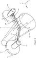
- the engine attachment pylon 18 further comprises a dynamic mass absorber 29, or resonator, as shown in figures 2 and 3 , according to the present invention, housed within the rigid structure 19.
- the terms dynamic mass absorber and resonator may be used interchangeably.
- the resonator 29 comprises a damping member 30 attached at one end to the second attachment means 25 and movably attached at the other end to a load transfer means 31.
- the load transfer means comprises 31 a lever 32 pivotally mounted around a pivot 33 and attached at one end to the damping member 30 and a fitting 34 at the other end.
- the fitting 34 attaches the lever 32 to the first attachment means 24.
- the damping member 30 has a narrow width compared to its length and extends, in-use, in the direction between the engine 11 and the fuselage 10.
- the damping member 30 comprises a lumped mass 35, or suspended ring mass, which is preferably located in the vicinity of the first attachment means 24.
- the pivot 33 is preferably a ball joint attaching the lever 32 to the end of a fixed member 36, having a narrow width compared to its length and which is attached at its other end to the second attachment means 25.
- vibrations comprising bending (B), torsion (TO), and tension (TE) and compression (C), as illustrated in figure 1 .
- the bending and torsion vibrations are attenuated by an arrangement of struts, which are not illustrated in the figure but are explained in FR2943643 .
- the struts serve to support the engine attachment pylons 17, 18 and reduce bending and torsion vibrations induced into the engine attachment pylon by the operation of the engine 11, 12 and during flight.
- the tension and compression vibrations in this example are attenuated by the resonator 29.
- Tension and compression vibrations are experienced by the fitting 34, and subsequently transferred to the damping member 30 by inducing oscillatory rotations in the lever 32 around the pivot 33. Then, the amplitude of the displacements at the attachment point of the damping member 30 to the lever 32 is attenuated by the inertia of the lumped mass 35, or ring mass, mounted onto the damping member 30, thus acting altogether as a damping force.
- the size of the ring mass 35 is chosen so that the dynamic mass absorber 29 can dissipate or absorb the vibration of the engine 11, 12.
- the weight of the lumped mass 35 is determined as a function of the amount of force required to react against the frequency of the vibrations seen at the location of the fitting 34.
- the principal advantage of this invention is to provide an engine attachment pylon 17, 18 which prevents tension and compression vibration from the engines 11, 12 from propagating into the cabin area of the fuselage. Also, the use of the junction 28 in the present invention minimises any vibrations from one engine attachment pylon 17 from propagating into the other engine attachment pylon 18. This is achieved because the junction 28 forms a hinge which isolates the movement from one engine attachment pylon 17 to the other 18.
- Another advantage of this invention is that the position of the lumped mass 35 being located in the vicinity of the first attachment means 24 prevents bending vibrations being induced into the engine attachment pylon 17 due to the existence of the resonator 29. Also, by implementing a lumped mass 35 as the means of damping, there is a reduced maintenance burden due to there being no moving parts and no hydraulic leakage.
- the lumped mass 35 could be replaced by a hydraulic damper.
- the pivot 33 may also be changed such that it is not a fixed member 36 having a narrow width compared to its length and extending to the second structural member 25 but takes the form of a rigid strut attached between the upper 26 and lower panels 27, at the location of the pivot 33.
- engine attachment configurations other than a rear mounted configuration with two engines mounted on engine attachment pylons 17, 18 raised by 30° from the horizontal (y) axis of an aircraft fuselage are possible.
- the engine attachment pylon according to the present invention could easily be adapted for other configurations.
- One such configuration would be to attach the second structural member to the fuselage. In this case, there is no need for a junction connecting the two engine attachment pylons and it would be appreciated that there would be a reduction in structural mass as a result.
- the engine attachment pylon could also be relocated to beneath the wing. In this case, the resonator within the engine attachment pylon would extend vertically in the direction between the engine and the wing.
Landscapes
- Engineering & Computer Science (AREA)
- Aviation & Aerospace Engineering (AREA)
- Vibration Prevention Devices (AREA)
Abstract
Description
- The present invention relates to an engine attachment pylon for attaching an aircraft engine to a fuselage of an aircraft.
- A known engine attachment pylon of this type is described in
FR2943623 FR2943623 - According to the first aspect of the invention there is provided An engine attachment pylon, for mounting an aircraft engine to an aircraft structure, comprising a rigid structure housing a dynamic mass absorber which is tuned to absorb vibrations of the aircraft engine; the rigid structure substantially forming a box and comprising a first and a second attachment means to connect the engine and the fuselage respectively.
- According to a second aspect of the invention there is provided An engine attachment assembly comprising a rear portion of an aircraft fuselage, two aircraft engines, and two engine attachment pylons according to any of the preceding claims, characterised in that each engine attachment pylon connects each engine to the fuselage and that the engine attachment pylon according to any of the preceding claims such that the engine attachment pylons are joined on a vertical plane (P) within the aircraft fuselage by a junction.
- The invention will now be described by way of example with reference to the accompanying drawings, of which:-
-
Figure 1 is a perspective view of a rear portion of a fuselage having two engines attached to it by means of two engine attachment pylons; -
Figure 2 is a similar view asfigure 1 showing a dynamic mass absorber located inside each engine attachment pylon according to the present invention; and -
Figure 3 is a detailed view of the resonator according to arrow F offigure 2 . - With reference to
figure 1 , there is shown a rear portion of afuselage 10 of an aircraft having a central longitudinal axis (x). The description will be done using a conventional axis system, comprising a longitudinal (x), a horizontal (y), and a vertical (z) axis. The rear portion of thefuselage 10 comprises twoengines fuselage 10. In this example, each engine comprises anacelle open fan blades engine attachment pylon rigid structure 19 covered by aerodynamic fairings, in particular afront fairing 20 which forms a leading edge and arear fairing 21 which forms a trailing edge of the pylon. With reference tofigure 3 , therigid structure 19 forms substantially a box, which comprises afront spar 22, arear spar 23, connected together by a first attachment means 24 and a second attachment means 25 extending perpendicularly between each spar, and sealed with an upper 26 and alower panel 27. With reference tofigure 2 , bothrigid structures 19 are joined together on a vertical plane (P) passing through the longitudinal (x) axis of thefuselage 10 by ajunction 28. Each rigid structure passes through openings in the fuselage, as explained inFR2943643 junction 28 which is substantially a hinge. The first attachment means 24 is conventionally rigidly attached to the engine nacelle. Therigid structure 19 is attached to thefuselage 10 internally by means of struts, as explained inFR2943643 - The
engine attachment pylon 18 further comprises a dynamic mass absorber 29, or resonator, as shown infigures 2 and3 , according to the present invention, housed within therigid structure 19. The terms dynamic mass absorber and resonator may be used interchangeably. With reference tofigure 3 , theresonator 29 comprises adamping member 30 attached at one end to the second attachment means 25 and movably attached at the other end to a load transfer means 31. The load transfer means comprises 31 alever 32 pivotally mounted around apivot 33 and attached at one end to the dampingmember 30 and afitting 34 at the other end. The fitting 34 attaches thelever 32 to the first attachment means 24. Thedamping member 30 has a narrow width compared to its length and extends, in-use, in the direction between theengine 11 and thefuselage 10. Thedamping member 30 comprises a lumpedmass 35, or suspended ring mass, which is preferably located in the vicinity of the first attachment means 24. Thepivot 33 is preferably a ball joint attaching thelever 32 to the end of a fixedmember 36, having a narrow width compared to its length and which is attached at its other end to the second attachment means 25. - During flight and operation of the engines, vibrations comprising bending (B), torsion (TO), and tension (TE) and compression (C), as illustrated in
figure 1 , will be induced and transferred to the fuselage. The bending and torsion vibrations are attenuated by an arrangement of struts, which are not illustrated in the figure but are explained inFR2943643 engine attachment pylons engine resonator 29. Tension and compression vibrations are experienced by the fitting 34, and subsequently transferred to the dampingmember 30 by inducing oscillatory rotations in thelever 32 around thepivot 33. Then, the amplitude of the displacements at the attachment point of thedamping member 30 to thelever 32 is attenuated by the inertia of the lumpedmass 35, or ring mass, mounted onto thedamping member 30, thus acting altogether as a damping force. The size of thering mass 35 is chosen so that the dynamic mass absorber 29 can dissipate or absorb the vibration of theengine mass 35, is determined as a function of the amount of force required to react against the frequency of the vibrations seen at the location of thefitting 34. - The principal advantage of this invention is to provide an
engine attachment pylon engines junction 28 in the present invention minimises any vibrations from oneengine attachment pylon 17 from propagating into the otherengine attachment pylon 18. This is achieved because thejunction 28 forms a hinge which isolates the movement from oneengine attachment pylon 17 to the other 18. - Another advantage of this invention is that the position of the lumped
mass 35 being located in the vicinity of the first attachment means 24 prevents bending vibrations being induced into theengine attachment pylon 17 due to the existence of theresonator 29. Also, by implementing a lumpedmass 35 as the means of damping, there is a reduced maintenance burden due to there being no moving parts and no hydraulic leakage. - Alternatively, the lumped
mass 35 could be replaced by a hydraulic damper. Thepivot 33 may also be changed such that it is not a fixedmember 36 having a narrow width compared to its length and extending to the secondstructural member 25 but takes the form of a rigid strut attached between the upper 26 andlower panels 27, at the location of thepivot 33. - It would be appreciated that engine attachment configurations other than a rear mounted configuration with two engines mounted on
engine attachment pylons
Claims (7)
- An engine attachment pylon (17), for mounting an aircraft engine (11) to an aircraft structure, comprising a rigid structure (19) housing a dynamic mass absorber (29) which is tuned to absorb vibrations of the aircraft engine (11); the rigid structure (19) substantially forming a box and comprising a first (24) and a second attachment means (25) to connect the engine (11) and the fuselage (10) respectively.
- The engine attachment means according to claim 1 characterised in the dynamic mass absorber (29) comprises a damping member (30) suspended inside the rigid structure (19).
- The engine attachment pylon according to claim 2, characterised in that the dynamic mass absorber (29) further comprises a load transfer means (31) configured to connect the damping member (30) to the first attachment means (24).
- The engine attachment pylon according to claim 3 wherein the load transfer means (31) comprises a lever (32), pivotally mounted around a pivot (33), and connected at one end to the damping member (30) and at the other end to a fitting (34) mounted on the first attachment means (24).
- The engine attachment pylon (17) according to claims 2 to 4, wherein the damping member (30) comprises the lumped mass (35).
- An engine attachment assembly comprising a rear portion of an aircraft fuselage (10), two aircraft engines (11), (12), and two engine attachment pylons (17), (18) according to any of the preceding claims, characterised in that each engine attachment pylon (17), (18) connects each engine to the fuselage and that the engine attachment pylon according to any of the preceding claims such that the engine attachment pylons are joined on a vertical plane (P) within the aircraft fuselage by a junction (28).
- The engine attachment assembly according to claim 6 wherein the junction (28) forms a hinge between the second attachment means (25) of each engine attachment pylon (17), (18) at their upper most edge when in-use.
Priority Applications (3)
| Application Number | Priority Date | Filing Date | Title |
|---|---|---|---|
| EP12157059.2A EP2631180B1 (en) | 2012-02-27 | 2012-02-27 | An engine attachment pylon |
| CN201210472436.1A CN103287580B (en) | 2012-02-27 | 2012-11-20 | Engine attachment pylon |
| US13/777,514 US8910904B2 (en) | 2012-02-27 | 2013-02-26 | Engine attachment pylon |
Applications Claiming Priority (1)
| Application Number | Priority Date | Filing Date | Title |
|---|---|---|---|
| EP12157059.2A EP2631180B1 (en) | 2012-02-27 | 2012-02-27 | An engine attachment pylon |
Publications (2)
| Publication Number | Publication Date |
|---|---|
| EP2631180A1 true EP2631180A1 (en) | 2013-08-28 |
| EP2631180B1 EP2631180B1 (en) | 2014-04-02 |
Family
ID=45771690
Family Applications (1)
| Application Number | Title | Priority Date | Filing Date |
|---|---|---|---|
| EP12157059.2A Not-in-force EP2631180B1 (en) | 2012-02-27 | 2012-02-27 | An engine attachment pylon |
Country Status (3)
| Country | Link |
|---|---|
| US (1) | US8910904B2 (en) |
| EP (1) | EP2631180B1 (en) |
| CN (1) | CN103287580B (en) |
Cited By (5)
| Publication number | Priority date | Publication date | Assignee | Title |
|---|---|---|---|---|
| US20150259074A1 (en) * | 2013-12-23 | 2015-09-17 | Airbus Operations (S.A.S.) | Aircraft assembly comprising a mounting strut built into the nacelle and arranged at the rear section of the fuselage |
| US9738373B2 (en) | 2011-01-17 | 2017-08-22 | Airbus Operations (S.A.S.) | Fish joint device having an improved mechanical hold |
| US9862497B2 (en) | 2013-12-17 | 2018-01-09 | Airbus Operations (S.A.S.) | Assembly for an aircraft, comprising an engine attachment body partially produced in one piece with an internal stiffening rib of an attachment pylon box section |
| US9868545B2 (en) | 2013-12-19 | 2018-01-16 | Airbus Operations (S.A.S.) | Primary structure for an attachment pylon with firewall and thermal layers |
| US9889943B2 (en) | 2013-12-17 | 2018-02-13 | Airbus Operations (S.A.S.) | Assembly for an aircraft, comprising an engine attachment body equipped with at least one shackle support fitting that passes into the box section of the attachment pylon |
Families Citing this family (4)
| Publication number | Priority date | Publication date | Assignee | Title |
|---|---|---|---|---|
| US9238511B2 (en) * | 2014-03-04 | 2016-01-19 | Mra Systems, Inc. | Engine pylon structure |
| EP3103725B1 (en) * | 2015-06-12 | 2018-04-25 | Airbus Operations, S.L. | Aircraft with an auxiliary power unit attached to the aircraft fuselage by means of an attachment system |
| FR3060531B1 (en) * | 2016-12-20 | 2019-05-31 | Airbus Operations | REAR AIRCRAFT PART COMPRISING A FUSELAGE FRAME SUPPORTING TWO PARTIALLY BITTED ENGINES |
| CN109573067A (en) * | 2018-12-04 | 2019-04-05 | 中国航空工业集团公司西安飞机设计研究所 | A kind of L-type engine hanging joint |
Citations (5)
| Publication number | Priority date | Publication date | Assignee | Title |
|---|---|---|---|---|
| EP0311155A2 (en) * | 1987-09-29 | 1989-04-12 | The Boeing Company | Vibration isolating engine mount |
| EP0429100A1 (en) * | 1989-11-21 | 1991-05-29 | The Boeing Company | Vibration damping aircraft engine attachment |
| EP0872662A2 (en) * | 1997-04-17 | 1998-10-21 | Applied Power Inc. | Vibration absorbing systems |
| FR2943643A1 (en) | 2009-03-27 | 2010-10-01 | Sidel Participations | PALLETIZER WITH PREPARATION OF CASTING LAYERS |
| FR2943623A1 (en) | 2009-03-30 | 2010-10-01 | Airbus France | REAR AIRCRAFT PART COMPRISING A SUPPORT STRUCTURE OF OSCILLATING MOUNTED ENGINES ON FUSELAGE |
Family Cites Families (1)
| Publication number | Priority date | Publication date | Assignee | Title |
|---|---|---|---|---|
| FR2935955B1 (en) * | 2008-09-18 | 2010-10-15 | Airbus France | AIRCRAFT REAR PART COMPRISING A MOTOR SUPPORT STRUCTURE RELATED TO FUSELAGE BY AT LEAST ONE COMPULSORY SOLVENT BLOCKING ELEMENT. |
-
2012
- 2012-02-27 EP EP12157059.2A patent/EP2631180B1/en not_active Not-in-force
- 2012-11-20 CN CN201210472436.1A patent/CN103287580B/en not_active Expired - Fee Related
-
2013
- 2013-02-26 US US13/777,514 patent/US8910904B2/en active Active
Patent Citations (5)
| Publication number | Priority date | Publication date | Assignee | Title |
|---|---|---|---|---|
| EP0311155A2 (en) * | 1987-09-29 | 1989-04-12 | The Boeing Company | Vibration isolating engine mount |
| EP0429100A1 (en) * | 1989-11-21 | 1991-05-29 | The Boeing Company | Vibration damping aircraft engine attachment |
| EP0872662A2 (en) * | 1997-04-17 | 1998-10-21 | Applied Power Inc. | Vibration absorbing systems |
| FR2943643A1 (en) | 2009-03-27 | 2010-10-01 | Sidel Participations | PALLETIZER WITH PREPARATION OF CASTING LAYERS |
| FR2943623A1 (en) | 2009-03-30 | 2010-10-01 | Airbus France | REAR AIRCRAFT PART COMPRISING A SUPPORT STRUCTURE OF OSCILLATING MOUNTED ENGINES ON FUSELAGE |
Cited By (6)
| Publication number | Priority date | Publication date | Assignee | Title |
|---|---|---|---|---|
| US9738373B2 (en) | 2011-01-17 | 2017-08-22 | Airbus Operations (S.A.S.) | Fish joint device having an improved mechanical hold |
| US9862497B2 (en) | 2013-12-17 | 2018-01-09 | Airbus Operations (S.A.S.) | Assembly for an aircraft, comprising an engine attachment body partially produced in one piece with an internal stiffening rib of an attachment pylon box section |
| US9889943B2 (en) | 2013-12-17 | 2018-02-13 | Airbus Operations (S.A.S.) | Assembly for an aircraft, comprising an engine attachment body equipped with at least one shackle support fitting that passes into the box section of the attachment pylon |
| US9868545B2 (en) | 2013-12-19 | 2018-01-16 | Airbus Operations (S.A.S.) | Primary structure for an attachment pylon with firewall and thermal layers |
| US20150259074A1 (en) * | 2013-12-23 | 2015-09-17 | Airbus Operations (S.A.S.) | Aircraft assembly comprising a mounting strut built into the nacelle and arranged at the rear section of the fuselage |
| US10336458B2 (en) * | 2013-12-23 | 2019-07-02 | Airbus Operations (S.A.S.) | Aircraft assembly comprising a mounting strut built into the nacelle and arranged at the rear section of the fuselage |
Also Published As
| Publication number | Publication date |
|---|---|
| CN103287580B (en) | 2015-10-28 |
| CN103287580A (en) | 2013-09-11 |
| US8910904B2 (en) | 2014-12-16 |
| US20130221155A1 (en) | 2013-08-29 |
| EP2631180B1 (en) | 2014-04-02 |
Similar Documents
| Publication | Publication Date | Title |
|---|---|---|
| EP2631180B1 (en) | An engine attachment pylon | |
| US8646724B2 (en) | System for attaching two components together, such as an aircraft engine and the mounting pylon thereof | |
| EP2718185B1 (en) | System and method for mounting an aircraft engine | |
| US10494113B2 (en) | Aircraft engine assembly, comprising an engine attachment device equipped with structural movable cowls connected to the central box | |
| JPH03169799A (en) | Device for attaching an engine to an aircraft body | |
| RU2468963C2 (en) | Fan body support frame mounted at nacelle attachment pylon and air intake | |
| CN103303484B (en) | A kind of equipment and the method being used for operating electromotor | |
| RU2429168C2 (en) | Aircraft power plant with fan housing support assembly mounted on two separate elements | |
| JP2010529346A (en) | Aircraft propulsion assembly with sliding nacelle | |
| CN104724291A (en) | Assembly for aircraft, and aircraft | |
| US20110155841A1 (en) | Vibration damper mechanism, and a flying machine including a carrier structure and a rotor provided with such a mechanism | |
| CA2487839C (en) | Structure for mounting a turboprop under an aircraft wing | |
| CN105000187B (en) | Component and aircraft for aircraft | |
| CN106428578A (en) | Engine assembly for an aircraft and aircraft comprising engine assembly | |
| CN101484359A (en) | Aircraft engine assembly comprising a junction aerodynamic fairing mounted on two separate elements | |
| CN101180211A (en) | Turbojet engine pylons for aircraft | |
| CA2929110A1 (en) | Assembly for an aircraft including a fitting secured to the upper surface of a wing box, for mounting an engine strut to said wing box | |
| CN108725806A (en) | Engine pack for aircraft and relevant aircraft | |
| US20170197724A1 (en) | Aircraft engine assembly, comprising an attachment device for the engine equipped with a structural cover attached on a central box | |
| CN107021234A (en) | The engine pack of the aircraft of rear engine attachment including formula in the form of shackles | |
| JP2017165394A (en) | Performance-enhanced jet engine prop | |
| GB2527709B (en) | Structure for suspending a twin prop-fan engine from a structural element of an aircraft | |
| EP3181458B1 (en) | Suspension system for an aircraft auxiliary power unit | |
| US10106266B2 (en) | Suspension structure for suspending a turboprop having two unducted propellers from a structural element of an aircraft with rigid fastening of the air intake structure | |
| CN101180213A (en) | aircraft engine components |
Legal Events
| Date | Code | Title | Description |
|---|---|---|---|
| PUAI | Public reference made under article 153(3) epc to a published international application that has entered the european phase |
Free format text: ORIGINAL CODE: 0009012 |
|
| 17P | Request for examination filed |
Effective date: 20120227 |
|
| AK | Designated contracting states |
Kind code of ref document: A1 Designated state(s): AL AT BE BG CH CY CZ DE DK EE ES FI FR GB GR HR HU IE IS IT LI LT LU LV MC MK MT NL NO PL PT RO RS SE SI SK SM TR |
|
| AX | Request for extension of the european patent |
Extension state: BA ME |
|
| GRAP | Despatch of communication of intention to grant a patent |
Free format text: ORIGINAL CODE: EPIDOSNIGR1 |
|
| INTG | Intention to grant announced |
Effective date: 20131107 |
|
| GRAS | Grant fee paid |
Free format text: ORIGINAL CODE: EPIDOSNIGR3 |
|
| GRAA | (expected) grant |
Free format text: ORIGINAL CODE: 0009210 |
|
| AK | Designated contracting states |
Kind code of ref document: B1 Designated state(s): AL AT BE BG CH CY CZ DE DK EE ES FI FR GB GR HR HU IE IS IT LI LT LU LV MC MK MT NL NO PL PT RO RS SE SI SK SM TR |
|
| REG | Reference to a national code |
Ref country code: GB Ref legal event code: FG4D |
|
| REG | Reference to a national code |
Ref country code: AT Ref legal event code: REF Ref document number: 659926 Country of ref document: AT Kind code of ref document: T Effective date: 20140415 Ref country code: CH Ref legal event code: EP |
|
| REG | Reference to a national code |
Ref country code: IE Ref legal event code: FG4D |
|
| REG | Reference to a national code |
Ref country code: DE Ref legal event code: R096 Ref document number: 602012001253 Country of ref document: DE Effective date: 20140515 |
|
| REG | Reference to a national code |
Ref country code: AT Ref legal event code: MK05 Ref document number: 659926 Country of ref document: AT Kind code of ref document: T Effective date: 20140402 |
|
| REG | Reference to a national code |
Ref country code: NL Ref legal event code: VDEP Effective date: 20140402 |
|
| REG | Reference to a national code |
Ref country code: LT Ref legal event code: MG4D |
|
| PG25 | Lapsed in a contracting state [announced via postgrant information from national office to epo] |
Ref country code: BG Free format text: LAPSE BECAUSE OF FAILURE TO SUBMIT A TRANSLATION OF THE DESCRIPTION OR TO PAY THE FEE WITHIN THE PRESCRIBED TIME-LIMIT Effective date: 20140702 Ref country code: NL Free format text: LAPSE BECAUSE OF FAILURE TO SUBMIT A TRANSLATION OF THE DESCRIPTION OR TO PAY THE FEE WITHIN THE PRESCRIBED TIME-LIMIT Effective date: 20140402 Ref country code: FI Free format text: LAPSE BECAUSE OF FAILURE TO SUBMIT A TRANSLATION OF THE DESCRIPTION OR TO PAY THE FEE WITHIN THE PRESCRIBED TIME-LIMIT Effective date: 20140402 Ref country code: LT Free format text: LAPSE BECAUSE OF FAILURE TO SUBMIT A TRANSLATION OF THE DESCRIPTION OR TO PAY THE FEE WITHIN THE PRESCRIBED TIME-LIMIT Effective date: 20140402 Ref country code: CZ Free format text: LAPSE BECAUSE OF FAILURE TO SUBMIT A TRANSLATION OF THE DESCRIPTION OR TO PAY THE FEE WITHIN THE PRESCRIBED TIME-LIMIT Effective date: 20140402 Ref country code: NO Free format text: LAPSE BECAUSE OF FAILURE TO SUBMIT A TRANSLATION OF THE DESCRIPTION OR TO PAY THE FEE WITHIN THE PRESCRIBED TIME-LIMIT Effective date: 20140702 Ref country code: IS Free format text: LAPSE BECAUSE OF FAILURE TO SUBMIT A TRANSLATION OF THE DESCRIPTION OR TO PAY THE FEE WITHIN THE PRESCRIBED TIME-LIMIT Effective date: 20140802 Ref country code: GR Free format text: LAPSE BECAUSE OF FAILURE TO SUBMIT A TRANSLATION OF THE DESCRIPTION OR TO PAY THE FEE WITHIN THE PRESCRIBED TIME-LIMIT Effective date: 20140703 Ref country code: CY Free format text: LAPSE BECAUSE OF FAILURE TO SUBMIT A TRANSLATION OF THE DESCRIPTION OR TO PAY THE FEE WITHIN THE PRESCRIBED TIME-LIMIT Effective date: 20140402 |
|
| PG25 | Lapsed in a contracting state [announced via postgrant information from national office to epo] |
Ref country code: SE Free format text: LAPSE BECAUSE OF FAILURE TO SUBMIT A TRANSLATION OF THE DESCRIPTION OR TO PAY THE FEE WITHIN THE PRESCRIBED TIME-LIMIT Effective date: 20140402 Ref country code: AT Free format text: LAPSE BECAUSE OF FAILURE TO SUBMIT A TRANSLATION OF THE DESCRIPTION OR TO PAY THE FEE WITHIN THE PRESCRIBED TIME-LIMIT Effective date: 20140402 Ref country code: RS Free format text: LAPSE BECAUSE OF FAILURE TO SUBMIT A TRANSLATION OF THE DESCRIPTION OR TO PAY THE FEE WITHIN THE PRESCRIBED TIME-LIMIT Effective date: 20140402 Ref country code: PL Free format text: LAPSE BECAUSE OF FAILURE TO SUBMIT A TRANSLATION OF THE DESCRIPTION OR TO PAY THE FEE WITHIN THE PRESCRIBED TIME-LIMIT Effective date: 20140402 Ref country code: LV Free format text: LAPSE BECAUSE OF FAILURE TO SUBMIT A TRANSLATION OF THE DESCRIPTION OR TO PAY THE FEE WITHIN THE PRESCRIBED TIME-LIMIT Effective date: 20140402 Ref country code: HR Free format text: LAPSE BECAUSE OF FAILURE TO SUBMIT A TRANSLATION OF THE DESCRIPTION OR TO PAY THE FEE WITHIN THE PRESCRIBED TIME-LIMIT Effective date: 20140402 Ref country code: ES Free format text: LAPSE BECAUSE OF FAILURE TO SUBMIT A TRANSLATION OF THE DESCRIPTION OR TO PAY THE FEE WITHIN THE PRESCRIBED TIME-LIMIT Effective date: 20140402 |
|
| PG25 | Lapsed in a contracting state [announced via postgrant information from national office to epo] |
Ref country code: PT Free format text: LAPSE BECAUSE OF FAILURE TO SUBMIT A TRANSLATION OF THE DESCRIPTION OR TO PAY THE FEE WITHIN THE PRESCRIBED TIME-LIMIT Effective date: 20140804 |
|
| REG | Reference to a national code |
Ref country code: DE Ref legal event code: R097 Ref document number: 602012001253 Country of ref document: DE |
|
| PG25 | Lapsed in a contracting state [announced via postgrant information from national office to epo] |
Ref country code: DK Free format text: LAPSE BECAUSE OF FAILURE TO SUBMIT A TRANSLATION OF THE DESCRIPTION OR TO PAY THE FEE WITHIN THE PRESCRIBED TIME-LIMIT Effective date: 20140402 Ref country code: RO Free format text: LAPSE BECAUSE OF FAILURE TO SUBMIT A TRANSLATION OF THE DESCRIPTION OR TO PAY THE FEE WITHIN THE PRESCRIBED TIME-LIMIT Effective date: 20140402 Ref country code: EE Free format text: LAPSE BECAUSE OF FAILURE TO SUBMIT A TRANSLATION OF THE DESCRIPTION OR TO PAY THE FEE WITHIN THE PRESCRIBED TIME-LIMIT Effective date: 20140402 Ref country code: BE Free format text: LAPSE BECAUSE OF FAILURE TO SUBMIT A TRANSLATION OF THE DESCRIPTION OR TO PAY THE FEE WITHIN THE PRESCRIBED TIME-LIMIT Effective date: 20140402 Ref country code: SK Free format text: LAPSE BECAUSE OF FAILURE TO SUBMIT A TRANSLATION OF THE DESCRIPTION OR TO PAY THE FEE WITHIN THE PRESCRIBED TIME-LIMIT Effective date: 20140402 |
|
| PLBE | No opposition filed within time limit |
Free format text: ORIGINAL CODE: 0009261 |
|
| STAA | Information on the status of an ep patent application or granted ep patent |
Free format text: STATUS: NO OPPOSITION FILED WITHIN TIME LIMIT |
|
| 26N | No opposition filed |
Effective date: 20150106 |
|
| PG25 | Lapsed in a contracting state [announced via postgrant information from national office to epo] |
Ref country code: IT Free format text: LAPSE BECAUSE OF FAILURE TO SUBMIT A TRANSLATION OF THE DESCRIPTION OR TO PAY THE FEE WITHIN THE PRESCRIBED TIME-LIMIT Effective date: 20140402 |
|
| REG | Reference to a national code |
Ref country code: DE Ref legal event code: R097 Ref document number: 602012001253 Country of ref document: DE Effective date: 20150106 |
|
| PG25 | Lapsed in a contracting state [announced via postgrant information from national office to epo] |
Ref country code: RS Free format text: LAPSE BECAUSE OF FAILURE TO SUBMIT A TRANSLATION OF THE DESCRIPTION OR TO PAY THE FEE WITHIN THE PRESCRIBED TIME-LIMIT Effective date: 20141119 |
|
| PG25 | Lapsed in a contracting state [announced via postgrant information from national office to epo] |
Ref country code: SI Free format text: LAPSE BECAUSE OF FAILURE TO SUBMIT A TRANSLATION OF THE DESCRIPTION OR TO PAY THE FEE WITHIN THE PRESCRIBED TIME-LIMIT Effective date: 20140402 |
|
| PG25 | Lapsed in a contracting state [announced via postgrant information from national office to epo] |
Ref country code: LU Free format text: LAPSE BECAUSE OF FAILURE TO SUBMIT A TRANSLATION OF THE DESCRIPTION OR TO PAY THE FEE WITHIN THE PRESCRIBED TIME-LIMIT Effective date: 20150227 |
|
| REG | Reference to a national code |
Ref country code: CH Ref legal event code: PL |
|
| PG25 | Lapsed in a contracting state [announced via postgrant information from national office to epo] |
Ref country code: LI Free format text: LAPSE BECAUSE OF NON-PAYMENT OF DUE FEES Effective date: 20150228 Ref country code: CH Free format text: LAPSE BECAUSE OF NON-PAYMENT OF DUE FEES Effective date: 20150228 Ref country code: MC Free format text: LAPSE BECAUSE OF FAILURE TO SUBMIT A TRANSLATION OF THE DESCRIPTION OR TO PAY THE FEE WITHIN THE PRESCRIBED TIME-LIMIT Effective date: 20140402 |
|
| REG | Reference to a national code |
Ref country code: IE Ref legal event code: MM4A |
|
| PG25 | Lapsed in a contracting state [announced via postgrant information from national office to epo] |
Ref country code: IE Free format text: LAPSE BECAUSE OF NON-PAYMENT OF DUE FEES Effective date: 20150227 |
|
| REG | Reference to a national code |
Ref country code: FR Ref legal event code: PLFP Year of fee payment: 5 |
|
| PG25 | Lapsed in a contracting state [announced via postgrant information from national office to epo] |
Ref country code: MT Free format text: LAPSE BECAUSE OF FAILURE TO SUBMIT A TRANSLATION OF THE DESCRIPTION OR TO PAY THE FEE WITHIN THE PRESCRIBED TIME-LIMIT Effective date: 20140402 |
|
| REG | Reference to a national code |
Ref country code: FR Ref legal event code: PLFP Year of fee payment: 6 |
|
| PG25 | Lapsed in a contracting state [announced via postgrant information from national office to epo] |
Ref country code: SM Free format text: LAPSE BECAUSE OF FAILURE TO SUBMIT A TRANSLATION OF THE DESCRIPTION OR TO PAY THE FEE WITHIN THE PRESCRIBED TIME-LIMIT Effective date: 20140402 Ref country code: HU Free format text: LAPSE BECAUSE OF FAILURE TO SUBMIT A TRANSLATION OF THE DESCRIPTION OR TO PAY THE FEE WITHIN THE PRESCRIBED TIME-LIMIT; INVALID AB INITIO Effective date: 20120227 |
|
| PG25 | Lapsed in a contracting state [announced via postgrant information from national office to epo] |
Ref country code: TR Free format text: LAPSE BECAUSE OF FAILURE TO SUBMIT A TRANSLATION OF THE DESCRIPTION OR TO PAY THE FEE WITHIN THE PRESCRIBED TIME-LIMIT Effective date: 20140402 |
|
| REG | Reference to a national code |
Ref country code: FR Ref legal event code: PLFP Year of fee payment: 7 |
|
| PG25 | Lapsed in a contracting state [announced via postgrant information from national office to epo] |
Ref country code: MK Free format text: LAPSE BECAUSE OF FAILURE TO SUBMIT A TRANSLATION OF THE DESCRIPTION OR TO PAY THE FEE WITHIN THE PRESCRIBED TIME-LIMIT Effective date: 20140402 |
|
| PG25 | Lapsed in a contracting state [announced via postgrant information from national office to epo] |
Ref country code: AL Free format text: LAPSE BECAUSE OF FAILURE TO SUBMIT A TRANSLATION OF THE DESCRIPTION OR TO PAY THE FEE WITHIN THE PRESCRIBED TIME-LIMIT Effective date: 20140402 |
|
| PGFP | Annual fee paid to national office [announced via postgrant information from national office to epo] |
Ref country code: IT Payment date: 20190321 Year of fee payment: 17 |
|
| REG | Reference to a national code |
Ref country code: DE Ref legal event code: R119 Ref document number: 602012001253 Country of ref document: DE |
|
| PG25 | Lapsed in a contracting state [announced via postgrant information from national office to epo] |
Ref country code: DE Free format text: LAPSE BECAUSE OF NON-PAYMENT OF DUE FEES Effective date: 20200901 |
|
| PGFP | Annual fee paid to national office [announced via postgrant information from national office to epo] |
Ref country code: GB Payment date: 20210219 Year of fee payment: 10 |
|
| PGFP | Annual fee paid to national office [announced via postgrant information from national office to epo] |
Ref country code: FR Payment date: 20220216 Year of fee payment: 11 |
|
| GBPC | Gb: european patent ceased through non-payment of renewal fee |
Effective date: 20220227 |
|
| PG25 | Lapsed in a contracting state [announced via postgrant information from national office to epo] |
Ref country code: GB Free format text: LAPSE BECAUSE OF NON-PAYMENT OF DUE FEES Effective date: 20220227 |
|
| PG25 | Lapsed in a contracting state [announced via postgrant information from national office to epo] |
Ref country code: FR Free format text: LAPSE BECAUSE OF NON-PAYMENT OF DUE FEES Effective date: 20230228 |