EP2631175A2 - Adaptive rotor blade - Google Patents
Adaptive rotor blade Download PDFInfo
- Publication number
- EP2631175A2 EP2631175A2 EP12198610.3A EP12198610A EP2631175A2 EP 2631175 A2 EP2631175 A2 EP 2631175A2 EP 12198610 A EP12198610 A EP 12198610A EP 2631175 A2 EP2631175 A2 EP 2631175A2
- Authority
- EP
- European Patent Office
- Prior art keywords
- rotor
- rotor assembly
- rotor blades
- blades
- assembly
- Prior art date
- Legal status (The legal status is an assumption and is not a legal conclusion. Google has not performed a legal analysis and makes no representation as to the accuracy of the status listed.)
- Granted
Links
Images
Classifications
-
- B—PERFORMING OPERATIONS; TRANSPORTING
- B64—AIRCRAFT; AVIATION; COSMONAUTICS
- B64C—AEROPLANES; HELICOPTERS
- B64C27/00—Rotorcraft; Rotors peculiar thereto
- B64C27/54—Mechanisms for controlling blade adjustment or movement relative to rotor head, e.g. lag-lead movement
- B64C27/58—Transmitting means, e.g. interrelated with initiating means or means acting on blades
- B64C27/59—Transmitting means, e.g. interrelated with initiating means or means acting on blades mechanical
- B64C27/615—Transmitting means, e.g. interrelated with initiating means or means acting on blades mechanical including flaps mounted on blades
-
- B—PERFORMING OPERATIONS; TRANSPORTING
- B64—AIRCRAFT; AVIATION; COSMONAUTICS
- B64C—AEROPLANES; HELICOPTERS
- B64C27/00—Rotorcraft; Rotors peculiar thereto
- B64C27/32—Rotors
- B64C27/325—Circulation-control rotors
-
- B—PERFORMING OPERATIONS; TRANSPORTING
- B64—AIRCRAFT; AVIATION; COSMONAUTICS
- B64C—AEROPLANES; HELICOPTERS
- B64C27/00—Rotorcraft; Rotors peculiar thereto
- B64C27/32—Rotors
- B64C27/46—Blades
- B64C27/463—Blade tips
-
- Y—GENERAL TAGGING OF NEW TECHNOLOGICAL DEVELOPMENTS; GENERAL TAGGING OF CROSS-SECTIONAL TECHNOLOGIES SPANNING OVER SEVERAL SECTIONS OF THE IPC; TECHNICAL SUBJECTS COVERED BY FORMER USPC CROSS-REFERENCE ART COLLECTIONS [XRACs] AND DIGESTS
- Y02—TECHNOLOGIES OR APPLICATIONS FOR MITIGATION OR ADAPTATION AGAINST CLIMATE CHANGE
- Y02T—CLIMATE CHANGE MITIGATION TECHNOLOGIES RELATED TO TRANSPORTATION
- Y02T50/00—Aeronautics or air transport
- Y02T50/30—Wing lift efficiency
Definitions
- Helicopter designs are typically the result of significant compromises to achieve both horizontal and vertical flight. This is particularly true of the helicopter rotor system.
- rotors may be optimized for, for example, high speed flight, low noise operation, high "g" maneuverability, or heavy lifting capability.
- the art would well receive a rotor system which can adapt to more than one of the above performance attributes.
- a method of operating a rotor assembly of a rotary wing aircraft includes rotating a plurality of rotor blades about a rotor shaft. Two or more active adaptive devices located at one or more rotor blades of the plurality of rotor blades are activated and change one or more operational characteristics of the rotor assembly.
- the flaps 28 When the one or more flaps 28 are activated at the same or higher harmonic frequencies of rotational speed of the rotor assembly 12, for example, the flaps 28 are activated and deactivated at a rate at or greater than once per revolution of the rotor assembly 12, vibration and noise of the rotor assembly 12 can be suppressed, and efficiency can be increased. Further, by activating the one or more flaps 28 discretely at a retreating side of the rotor assembly 12, at each rotor blade 20 when it is retreating, the flap 28 creates a higher lift coefficient, thus creating more blade lift for the same retreating side airflow. This advantageously postpones retreating blade stall to higher flight airspeeds.
- activating flaps 28 collectively downwardly when the aircraft 10 is in hover effectively twists the rotor blade 20.
- the increased twist is beneficial at higher gross weights because the airflow through the rotor 12 increases, and increasing the twist better aligns the rotor blades 20 with the higher airflow. The net result is higher rotor efficiency at high gross aircraft 10 weights.
Landscapes
- Engineering & Computer Science (AREA)
- Mechanical Engineering (AREA)
- Aviation & Aerospace Engineering (AREA)
- Structures Of Non-Positive Displacement Pumps (AREA)
- Control Of Turbines (AREA)
Abstract
Description
- This invention was made with Government support under Other Transaction No. HR0011-10-9-0002 awarded by DARPA. The Government has certain rights in this invention.
- Helicopter designs are typically the result of significant compromises to achieve both horizontal and vertical flight. This is particularly true of the helicopter rotor system. Depending on the helicopter, rotors may be optimized for, for example, high speed flight, low noise operation, high "g" maneuverability, or heavy lifting capability. Rotor design features enhancing vertical performance attributes, such as heavy lift capability, often directly conflict with features enhancing forward flight, especially high speed flight. The art would well receive a rotor system which can adapt to more than one of the above performance attributes.
- A rotor assembly for a rotary wing aircraft includes a plurality of rotor blades operably connected to a rotor shaft. Two or more active adaptive devices are located on one or more rotor blades of the plurality of rotor blades. The one or more active adaptive devices are operably connected to an aircraft flight control system such that, when activated, the one or more active adaptive devices change one or more operational characteristics of the rotor assembly.
- Further embodiments may comprise, alone or in combination, any one of the following features:
- One or more adaptive devices may include at least one flap disposed at a trailing edge of at least one rotor blade of the plurality of rotor blades.
- A position of the at least one flap may be controlled by one or more electromechanical actuators disposed at the at least one rotor blade,
- Activation of the one at least one flap at a selected rotational speed of the rotor assembly may result in suppression of at least one of vibration or noise of the rotor assembly.
- Activation of the at least flap in a retreating portion of rotation of the rotor blade may result in an increase in at least one of lift of the rotor assembly or flight speed of the aircraft.
- The one or more adaptive devices may include a spar air duct extending along one or more rotor blades of the plurality of rotor blades, the spar air duct having at least one inlet and at least one outlet.
- The at least one outlet may be disposed in proximity to a leading edge of the one or more rotor blades.
- Urging airflow from the spar air duct through the at least one outlet toward the leading edge may result in an increase in lift of the one or more rotor blades.
- The at least one outlet may be disposed at a blade tip of the one or more rotor blades.
- Urging airflow from the spar air duct through the at least one outlet may result in a reduction in noise of the rotor assembly.
- The rotor assembly may further comprise one or more valves to control an airflow through the at least one outlet.
- A method of operating a rotor assembly of a rotary wing aircraft includes rotating a plurality of rotor blades about a rotor shaft. Two or more active adaptive devices located at one or more rotor blades of the plurality of rotor blades are activated and change one or more operational characteristics of the rotor assembly.
- Further embodiments of such method may include, alone or in combination, any one of the following features:
- Activating one or more adaptive devices may comprise activating at least one flap disposed at a trailing edge of at least one rotor blade of the plurality of rotor blades.
- The at least one flap may be activated at a selected rotational speed of the rotor assembly.
- Changing one or more operational characteristics of the rotor assembly may comprise suppressing at least one of vibration or noise of the rotor assembly.
- These and other advantages and features will become more apparent from the following description taken in conjunction with the drawings.
- The subject matter, which is regarded as the invention, is particularly pointed out and distinctly claimed in the claims at the conclusion of the specification. The foregoing and other features, and advantages of the invention are apparent from the following detailed description taken in conjunction with the accompanying drawings in which:
-
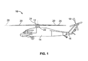
FIG. 1 is a schematic view of an embodiment of a rotary wing aircraft; -
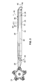
FIG. 2 is a plan view of an embodiment of a rotor blade; -
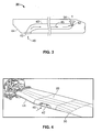
FIG. 3 is a plan view of an embodiment of a rotor blade including an internal duct; -
FIG. 4 is a perspective view of an embodiment of a rotor blade having an air inlet; -
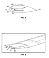
FIG. 5 is a cross-sectional view of an embodiment of a rotor blade having an internal duct; and -
FIG. 6 is a perspective view of an embodiment of a rotor blade having an air outlet. - The detailed description explains embodiments of the invention, together with advantages and features, by way of example with reference to the drawings.
-
FIG. 1 is a schematic illustration of arotary wing aircraft 10 having amain rotor assembly 12. Theaircraft 10 includes anairframe 14 having an extendingtail 16 at which is mounted ananti-torque rotor 18. Although the configuration illustrated is a single main rotor helicopter, it is to be appreciated that other machines such as tandem rotor helicopters, turbo-props, tilt-rotor aircraft, and co-axial rotorcraft will also benefit from the system of the present disclosure. Themain rotor assembly 12 includes a plurality ofrotor blades 20 located about arotor shaft 22. Therotor blades 20 are operably connected to therotor shaft 22 via aswashplate 24, which allows for a change in pitch of therotor blades 20 about ablade axis 26. - The
rotor blades 20 include one or more active adaptive devices which allow therotor blades 20 andmain rotor assembly 12 to adapt to different flight missions and the unique requirements of each flight mission. The adaptive devices, when selectively activated based on mission requirements, may, for example, increasemaximum rotor blade 20 lift, suppress characteristics such as vibration and/or noise, increase flight speed, improve hover performance at high gross weights, increase maneuverability, or the like. A primary goal is to use the combination of multiple devices to enhance overall rotor attributes and performance. An on blade device typically enhances one or two rotor attributes such as low noise, low vibration, efficiency, maneuverability, payload, or speed. The purpose is to use multiple devices to provide a rotor increased capabilities among all these attributes. The devices can be turned on or off as the mission segment requires. The devices are also designed to work synergistically to maximize rotor capabilities. - Referring to
FIG. 2 , one example of adaptive device is one ormore flaps 28 located, in some embodiments, at atrailing edge 30 of therotor blade 20.Flaps 28 may be in the form of conventional plain flaps, movable Gurney flaps, or other trailing edge devices used to change airfoil lift, drag, and moment. Theflaps 28 are driven by one or more actuators, for example, one or moreelectromechanical actuators 32 or pneumatic actuators or the like located at therotor blade 20. Theelectromechanical actuators 32 are operably connected to theflaps 28 and to a flight control system of theaircraft 10, for example, a flight control computer 34 (shown inFIG. 1 ). When the one ormore flaps 28 are activated at the same or higher harmonic frequencies of rotational speed of therotor assembly 12, for example, theflaps 28 are activated and deactivated at a rate at or greater than once per revolution of therotor assembly 12, vibration and noise of therotor assembly 12 can be suppressed, and efficiency can be increased. Further, by activating the one ormore flaps 28 discretely at a retreating side of therotor assembly 12, at eachrotor blade 20 when it is retreating, theflap 28 creates a higher lift coefficient, thus creating more blade lift for the same retreating side airflow. This advantageously postpones retreating blade stall to higher flight airspeeds. Also, activatingflaps 28 collectively downwardly when theaircraft 10 is in hover effectively twists therotor blade 20. The increased twist is beneficial at higher gross weights because the airflow through therotor 12 increases, and increasing the twist better aligns therotor blades 20 with the higher airflow. The net result is higher rotor efficiency at highgross aircraft 10 weights. - Referring to
FIG. 3 , in some embodiments, therotor blade 20 includes one ormore air outlets 36 at or near a leadingedge 38 of therotor blade 20. In some embodiments, theair outlets 36 are located at a leading edgeupper surface 60 of therotor blade 20. Theair outlets 36 may be slot shaped and are connected to an internalspar air duct 40 extending along a span of therotor blade 20 from aduct inlet 42 to theair outlets 36. Theduct 40 is fed by the duct inlet 42 (best shown inFIG. 4 ), which in some embodiments is located at or near aroot 44 of thetrailing edge 30. Referring again toFIG. 3 , as therotor blade 20 rotates, anairflow 46 is centrifugally pumped into theduct 40 through theduct inlet 42 and is urged toward theair outlets 36. Theairflow 46 exits theair outlets 36 to increase maximum blade lift. Referring toFIG. 5 , maximum blade lift is increased by blowing the air through theair outlets 36 substantially tangentially to the upper surface in a rearward direction, toward the trailingedge 30 of therotor blade 20. Theairflow 46 energizes the boundary layer and delays separation as angle of attack is increased thus increasing maximum blade lift. Referring again toFIG. 3 , flow through theair outlets 36 may be controlled (turned on/off or metered) by one ormore valves 62 located between theduct 40 and theair outlets 36. Operation of the one ormore valves 60 may be controlled by theflight control computer 34. - It is highly desirable to reduce the noise of
rotor assembly 12 in flight. A powerful means to reduce noise is to reduce rotational speed ofrotor assembly 12. However, rotational speed reductions come at the expense of rotor assembly lift and aircraft speed and maneuverability. The reductions are due to rotor assembly stall occurring at reduced flight speeds and/or reduced gross weights. In order to maintain aircraft speed and maneuverability and not sacrifice aircraft gross weight, theflaps 28 andair outlets 34 are utilized at lower rotor assembly rotational speeds. Thus rotor assembly lift, and aircraft speed and maneuverability can be maintained at adequate levels. As such, synergy betweenflaps 28,outlets 34, and the rotational speed of therotor assembly 12 reduces rotor assembly noise levels. In some embodiments rotational speed reductions between about 10% and 15% can be attained. In situations where an increased rotor assembly rotational speed is required or desired, such as when increased gross weight capability is desired, another active measure may be utilized to reducerotor assembly 12 noise. For example, therotor blade 20 may include a tip jet outlet 48 (shown inFIG. 6 ) located at arotor blade tip 50 and connected to theduct 40. At increased rotor assembly speeds,airflow 46 through theduct 40 is directed through thetip jet outlet 48 instead of, or in addition to, through theair outlets 36. -
Airflow 46 pumped through theduct 40 creates a high pressure mass source at theblade tip 50. The mass source, when modulated by releasingairflow 46 through the tip jet valve andoutlet 48, at a once perrotor 12 revolution frequency cancelsrotor blade 20 thickness noise. Theairflow 46 released through thetip jet outlet 48 creates a positive pressure pulse shape which counteracts a negative pressure pulse shape of therotor blade 20.Rotor blade 20 noise is a result of this negative pressure pulse and by counteracting it with the positive pressure pulse therotor blade 20 noise is reduced. In some embodiments, theairflow 46 through thetip jet outlet 48 is activated when therotor blade 20 is advancing. Further, theairflow 46 through thetip jet outlet 48 may be modulated as a substantially constant flow to diffuse a vortex at theblade tip 50, thereby reducing blade vortex interaction noise. - While the invention has been described in detail in connection with only a limited number of embodiments, it should be readily understood that the invention is not limited to such disclosed embodiments. Rather, the invention can be modified to incorporate any number of variations, alterations, substitutions or equivalent arrangements not heretofore described, but which are commensurate with the spirit and scope of the invention. Additionally, while various embodiments of the invention have been described, it is to be understood that aspects of the invention may include only some of the described embodiments. Accordingly, the invention is not to be seen as limited by the foregoing description, but is only limited by the scope of the appended claims.
Claims (15)
- A rotor assembly for a rotary wing aircraft comprising:a plurality of rotor blades operably connected to a rotor shaft; andtwo or more active adaptive devices disposed at one or more rotor blades of the plurality of rotor blades, the one or more active adaptive devices operably connected to an aircraft flight control system such that, when activated, the one or more active adaptive devices change one or more operational characteristics of the rotor assembly.
- The rotor assembly of Claim 1, wherein the one or more adaptive devices include at least one flap disposed at a trailing edge of at least one rotor blade of the plurality of rotor blades.
- The rotor assembly of Claim 2, wherein a position of the at least one flap is controlled by one or more electromechanical actuators disposed at the at least one rotor blade.
- The rotor assembly of Claim 2 or 3, wherein activation of the one at least one flap at a selected rotational speed of the rotor assembly results in suppression of at least one of vibration or noise of the rotor assembly.
- The rotor assembly of any of Claims 2 to 4, wherein activation of the at least flap in a retreating portion of rotation of the rotor blade results in an increase in at least one of lift of the rotor assembly or flight speed of the aircraft.
- The rotor assembly of any of Claims 1 to 5, wherein the one or more adaptive devices include a spar air duct extending along one or more rotor blades of the plurality of rotor blades, the spar air duct having at least one inlet and at least one outlet.
- The rotor assembly of Claim 6, wherein the at least one outlet is disposed in proximity to a leading edge of the one or more rotor blades.
- The rotor assembly of Claim 7, wherein urging airflow from the spar air duct through the at least one outlet toward the leading edge results in an increase in lift of the one or more rotor blades.
- The rotor assembly of any of Claims 6 to 8, wherein the at least one outlet is disposed at a blade tip of the one or more rotor blades.
- The rotor assembly of Claim 9, wherein urging airflow from the spar air duct through the at least one outlet results in a reduction in noise of the rotor assembly.
- The rotor assembly of any of Claims 6 to 10, further comprising one or more valves to control an airflow through the at least one outlet.
- A method of operating a rotor assembly of a rotary wing aircraft comprising:rotating a plurality of rotor blades about a rotor shaft:activating two or more active adaptive devices disposed at one or more rotor blades of the plurality of rotor blades; andchanging one or more operational characteristics of the rotor assembly via the activation of the one or more active adaptive devices.
- The method of Claim 12, wherein activating one or more adaptive devices comprises activating at least one flap disposed at a trailing edge of at least one rotor blade of the plurality of rotor blades.
- The method of Claim 13, wherein the at least one flap is activated at a selected rotational speed of the rotor assembly.
- The method of Claim 14, wherein changing one or more operational characteristics of the rotor assembly comprises suppressing at least one of vibration or noise of the rotor assembly.
Applications Claiming Priority (1)
| Application Number | Priority Date | Filing Date | Title |
|---|---|---|---|
| US13/403,364 US9505492B2 (en) | 2012-02-23 | 2012-02-23 | Mission adaptive rotor blade |
Publications (3)
| Publication Number | Publication Date |
|---|---|
| EP2631175A2 true EP2631175A2 (en) | 2013-08-28 |
| EP2631175A3 EP2631175A3 (en) | 2017-12-27 |
| EP2631175B1 EP2631175B1 (en) | 2019-09-18 |
Family
ID=47603078
Family Applications (1)
| Application Number | Title | Priority Date | Filing Date |
|---|---|---|---|
| EP12198610.3A Not-in-force EP2631175B1 (en) | 2012-02-23 | 2012-12-20 | Adaptive rotor blade |
Country Status (2)
| Country | Link |
|---|---|
| US (1) | US9505492B2 (en) |
| EP (1) | EP2631175B1 (en) |
Cited By (1)
| Publication number | Priority date | Publication date | Assignee | Title |
|---|---|---|---|---|
| WO2015181552A1 (en) * | 2014-05-28 | 2015-12-03 | Agustawestland Limited | A rotor blade system |
Families Citing this family (14)
| Publication number | Priority date | Publication date | Assignee | Title |
|---|---|---|---|---|
| WO2016118226A1 (en) * | 2015-01-22 | 2016-07-28 | Sikorsky Aircraft Corporation | Low noise rotor blade design |
| US10302064B2 (en) * | 2015-07-30 | 2019-05-28 | The Boeing Company | Methods and systems for rotary wing active flow control |
| WO2017048683A1 (en) * | 2015-09-17 | 2017-03-23 | Sikorsky Aircraft Corporation | Stress reducing holes |
| US20180297692A1 (en) * | 2015-10-17 | 2018-10-18 | Sikorsky Aircraft Corporation | Reduced blade vortex interaction |
| US9592910B1 (en) | 2015-12-18 | 2017-03-14 | Amazon Technologies, Inc. | Geometrically reconfigurable propellers |
| US10287006B1 (en) | 2015-12-18 | 2019-05-14 | Amazon Technologies, Inc. | Adjustable propeller blades for sound control |
| US10370098B1 (en) * | 2015-12-18 | 2019-08-06 | Amazon Technologies, Inc. | Adjustable propeller blade with sound flaps |
| US11014661B2 (en) * | 2016-10-24 | 2021-05-25 | Sikorsky Aircraft Corporation | Tip jet orifice for aircraft brown out mitigation |
| CN109760823B (en) * | 2019-01-15 | 2021-07-13 | 北京航空航天大学 | A near-space propeller with active tip blowing |
| MX2019003715A (en) * | 2019-03-29 | 2020-09-30 | Rosado Rodrigo Gallardo | Induced autorotation rotary wing. |
| CN111252243B (en) * | 2020-01-21 | 2022-08-05 | 南京航空航天大学 | Helicopter rotor blade down-turning reverse blade tip driving mechanism based on centrifugal mass block |
| KR102384061B1 (en) * | 2020-06-29 | 2022-04-08 | 김병만 | Torque boosting blade |
| US20200339248A1 (en) * | 2020-06-30 | 2020-10-29 | Papa Abdoulaye MBODJ | Boundary layer suction design by using wingtip vortex for a lift-generating body |
| DE102021110538B4 (en) | 2021-04-26 | 2024-02-29 | Dr. Ing. H.C. F. Porsche Aktiengesellschaft | Aircraft propeller and aircraft |
Family Cites Families (39)
| Publication number | Priority date | Publication date | Assignee | Title |
|---|---|---|---|---|
| US2476002A (en) * | 1946-01-12 | 1949-07-12 | Edward A Stalker | Rotating wing |
| US2638990A (en) | 1947-04-01 | 1953-05-19 | Autogiro Co Of America | Aircraft sustaining rotor blade with airflow control |
| US2759548A (en) * | 1953-04-02 | 1956-08-21 | Yuan Shao Wen | Lift rotor control |
| US2959373A (en) | 1954-12-10 | 1960-11-08 | Daniel R Zuck | Convertiplane |
| US3100539A (en) * | 1961-08-14 | 1963-08-13 | Bell Aerospace Corp | Helicopter rotor blade |
| US3155341A (en) | 1963-04-05 | 1964-11-03 | Ryan Aeronautical Co | Convertiplane |
| US3713750A (en) | 1970-12-07 | 1973-01-30 | Us Navy | Circulation control rotor system |
| US4045146A (en) * | 1976-05-17 | 1977-08-30 | Avco Corporation | Helicopter rotor blade |
| US4507050A (en) | 1983-12-09 | 1985-03-26 | United Technologies Corporation | Pneumatic valve control for circulation control aircraft |
| US4534702A (en) | 1983-12-27 | 1985-08-13 | United Technologies Corporation | Pneumatic control valve actuator computer control arrangement |
| JPH06199295A (en) * | 1992-11-25 | 1994-07-19 | Mitsubishi Heavy Ind Ltd | Rotar blade for helicopter |
| US5588800B1 (en) * | 1994-05-31 | 2000-12-19 | Mcdonell Douglas Helicopter Co | Blade vortex interaction noise reduction techniques for a rotorcraft |
| JP2951540B2 (en) * | 1994-06-30 | 1999-09-20 | 川田工業株式会社 | Noise reduction device for rotorcraft |
| US5813625A (en) | 1996-10-09 | 1998-09-29 | Mcdonnell Douglas Helicopter Company | Active blowing system for rotorcraft vortex interaction noise reduction |
| US6131849A (en) | 1998-12-02 | 2000-10-17 | Mcdonnell Douglas Helicopter Company | Articulating/telescoping duct for reaction drive helicopters |
| US6203269B1 (en) * | 1999-02-25 | 2001-03-20 | United Technologies Corporation | Centrifugal air flow control |
| US6200096B1 (en) | 1999-04-16 | 2001-03-13 | Sikorsky Aircraft Corporation | Actuation system for an active rotor control system |
| US6295006B1 (en) | 1999-04-16 | 2001-09-25 | Sikorsky Aircraft Corporation | Flap angle measurement system for an active rotor control system |
| US6425553B1 (en) | 1999-08-20 | 2002-07-30 | West Virginia University | Piezoelectric actuators for circulation controlled rotorcraft |
| US6283406B1 (en) * | 1999-09-10 | 2001-09-04 | Gte Service Corporation | Use of flow injection and extraction to control blade vortex interaction and high speed impulsive noise in helicopters |
| US6932569B2 (en) | 2002-05-17 | 2005-08-23 | Sikorsky Aircraft Corporation | Active control of multi-element rotor blade airfoils |
| US6863239B2 (en) | 2003-02-27 | 2005-03-08 | General Dynamics Advanced Information Systems, Inc. | Fluid conduit for use with hydraulic actuator |
| US6948906B2 (en) | 2003-04-02 | 2005-09-27 | University Of Maryland | Rotor blade system with reduced blade-vortex interaction noise |
| US6984109B2 (en) * | 2003-12-04 | 2006-01-10 | Sikorsky Aircraft Corporation | Rotor blade pitch control assembly |
| US7275711B1 (en) | 2004-02-23 | 2007-10-02 | Kenneth Warren Flanigan | Gas-powered tip-jet-driven compound VTOL aircraft |
| USD524229S1 (en) | 2005-05-30 | 2006-07-04 | Sirorsky Aircraft Corporation | Rigid coaxial rotor helicopter with auxiliary propulsion (small) |
| USD524227S1 (en) | 2005-05-31 | 2006-07-04 | Sikorsky Aircraft Corporation | Rigid coaxial rotor unmanned helicopter with auxiliary propulsion |
| US7967239B2 (en) | 2005-05-31 | 2011-06-28 | Sikorsky Aircraft Corporation | Rotor drive and control system for a high speed rotary wing aircraft |
| USD524230S1 (en) | 2005-05-31 | 2006-07-04 | Sikorsky Aircraft Corporation | Rigid coaxial rotor helicopter with auxiliary propulsion (large) |
| US7611090B2 (en) | 2005-12-20 | 2009-11-03 | The Boeing Company | Reaction-drive rotorcraft having an adjustable blade jet |
| US7708229B1 (en) | 2006-03-22 | 2010-05-04 | West Virginia University | Circulation controlled airfoil |
| US7758310B2 (en) | 2007-01-15 | 2010-07-20 | Sikorsky Aircraft Corporation | Translational thrust system for a rotary wing aircraft |
| USD614559S1 (en) | 2007-09-14 | 2010-04-27 | Sikorsky Aircraft Corporation | Rotary-wing aircraft with a common dynamic system/backbone structure |
| CN101978160A (en) | 2007-11-06 | 2011-02-16 | 富莱克斯公司 | Active control surfaces for wind turbine blades |
| JP5319395B2 (en) | 2009-05-22 | 2013-10-16 | ヤンマー株式会社 | Ship with hydrofoil |
| DE102009047808B4 (en) | 2009-09-30 | 2018-01-25 | Infineon Technologies Austria Ag | Bipolar semiconductor device and method for producing a semiconductor diode |
| US8267653B2 (en) | 2010-12-21 | 2012-09-18 | General Electric Company | System and method of operating an active flow control system to manipulate a boundary layer across a rotor blade of a wind turbine |
| FR2969577B1 (en) | 2010-12-22 | 2012-12-21 | Eurocopter France | AIRCRAFT HAVING BACK-UP ROTOR, AND ASSOCIATED METHOD |
| US9120567B2 (en) * | 2012-06-11 | 2015-09-01 | Sikorsky Aircraft Corporation | High speed compound rotary wing aircraft |
-
2012
- 2012-02-23 US US13/403,364 patent/US9505492B2/en not_active Expired - Fee Related
- 2012-12-20 EP EP12198610.3A patent/EP2631175B1/en not_active Not-in-force
Non-Patent Citations (1)
| Title |
|---|
| None |
Cited By (3)
| Publication number | Priority date | Publication date | Assignee | Title |
|---|---|---|---|---|
| WO2015181552A1 (en) * | 2014-05-28 | 2015-12-03 | Agustawestland Limited | A rotor blade system |
| RU2702376C2 (en) * | 2014-05-28 | 2019-10-08 | Агустауэстлэнд Лимитед | Rotor blade system |
| US11618559B2 (en) | 2014-05-28 | 2023-04-04 | Leonardo Uk Limited | Rotor blade system |
Also Published As
| Publication number | Publication date |
|---|---|
| US20130224017A1 (en) | 2013-08-29 |
| US9505492B2 (en) | 2016-11-29 |
| EP2631175A3 (en) | 2017-12-27 |
| EP2631175B1 (en) | 2019-09-18 |
Similar Documents
| Publication | Publication Date | Title |
|---|---|---|
| US9505492B2 (en) | Mission adaptive rotor blade | |
| US9120567B2 (en) | High speed compound rotary wing aircraft | |
| US8727265B2 (en) | Helicopter with cycloidal rotor system | |
| EP2878532B1 (en) | Differential blade design for propeller noise reduction | |
| CN103097244B (en) | Airfoil tail boom | |
| US12397911B2 (en) | Flying vehicle rotor arrangement | |
| EP2431275B1 (en) | Rotor blade with integrated passive surface flap | |
| EP2957502B1 (en) | Convertible helicopter ring member | |
| US9359072B2 (en) | Rotor blade for a rotor of an aircraft designed to minimize noise emitted by the rotor | |
| CN103754362B (en) | A kind of lift rotor | |
| EP2316732B1 (en) | Active rotor blade control effector system for a rotary-wing aircraft | |
| EP3317180B1 (en) | Helicopter with anti-torque system, related kit and methods | |
| US10112697B2 (en) | Aircraft with thrust vectoring tail | |
| EP2581304A2 (en) | Rotor blade component cooling | |
| EP2687442A1 (en) | Airfoil shaped tail boom | |
| EP3181447B1 (en) | Active airflow system and method of reducing drag for aircraft | |
| EP3031720B1 (en) | Guide vanes for a pusher propeller for rotary wing aircraft | |
| EP3141473B1 (en) | Drag reduction of high speed aircraft with a coaxial-rotor system | |
| EP3878739B1 (en) | Bidirectional aircraft rotor | |
| US10814971B2 (en) | Tail rotor housing | |
| US10723451B2 (en) | Propeller rotor for a vertical take off and landing aircraft | |
| US20180281938A1 (en) | Low noise rotor blade design | |
| EP3693267B1 (en) | Low drag hub for rotor | |
| EP4361037B1 (en) | A rotorcraft with a tail boom having a ducted tail rotor | |
| KR20250082581A (en) | Aircraft |
Legal Events
| Date | Code | Title | Description |
|---|---|---|---|
| PUAI | Public reference made under article 153(3) epc to a published international application that has entered the european phase |
Free format text: ORIGINAL CODE: 0009012 |
|
| AK | Designated contracting states |
Kind code of ref document: A2 Designated state(s): AL AT BE BG CH CY CZ DE DK EE ES FI FR GB GR HR HU IE IS IT LI LT LU LV MC MK MT NL NO PL PT RO RS SE SI SK SM TR |
|
| AX | Request for extension of the european patent |
Extension state: BA ME |
|
| PUAL | Search report despatched |
Free format text: ORIGINAL CODE: 0009013 |
|
| AK | Designated contracting states |
Kind code of ref document: A3 Designated state(s): AL AT BE BG CH CY CZ DE DK EE ES FI FR GB GR HR HU IE IS IT LI LT LU LV MC MK MT NL NO PL PT RO RS SE SI SK SM TR |
|
| AX | Request for extension of the european patent |
Extension state: BA ME |
|
| RIC1 | Information provided on ipc code assigned before grant |
Ipc: B64C 27/615 20060101ALI20171123BHEP Ipc: B64C 27/32 20060101AFI20171123BHEP Ipc: B64C 27/46 20060101ALI20171123BHEP |
|
| STAA | Information on the status of an ep patent application or granted ep patent |
Free format text: STATUS: REQUEST FOR EXAMINATION WAS MADE |
|
| STAA | Information on the status of an ep patent application or granted ep patent |
Free format text: STATUS: EXAMINATION IS IN PROGRESS |
|
| 17P | Request for examination filed |
Effective date: 20180619 |
|
| RBV | Designated contracting states (corrected) |
Designated state(s): AL AT BE BG CH CY CZ DE DK EE ES FI FR GB GR HR HU IE IS IT LI LT LU LV MC MK MT NL NO PL PT RO RS SE SI SK SM TR |
|
| 17Q | First examination report despatched |
Effective date: 20180719 |
|
| GRAP | Despatch of communication of intention to grant a patent |
Free format text: ORIGINAL CODE: EPIDOSNIGR1 |
|
| STAA | Information on the status of an ep patent application or granted ep patent |
Free format text: STATUS: GRANT OF PATENT IS INTENDED |
|
| INTG | Intention to grant announced |
Effective date: 20190410 |
|
| GRAS | Grant fee paid |
Free format text: ORIGINAL CODE: EPIDOSNIGR3 |
|
| GRAA | (expected) grant |
Free format text: ORIGINAL CODE: 0009210 |
|
| STAA | Information on the status of an ep patent application or granted ep patent |
Free format text: STATUS: THE PATENT HAS BEEN GRANTED |
|
| AK | Designated contracting states |
Kind code of ref document: B1 Designated state(s): AL AT BE BG CH CY CZ DE DK EE ES FI FR GB GR HR HU IE IS IT LI LT LU LV MC MK MT NL NO PL PT RO RS SE SI SK SM TR |
|
| REG | Reference to a national code |
Ref country code: GB Ref legal event code: FG4D |
|
| REG | Reference to a national code |
Ref country code: CH Ref legal event code: EP |
|
| REG | Reference to a national code |
Ref country code: DE Ref legal event code: R096 Ref document number: 602012064070 Country of ref document: DE |
|
| REG | Reference to a national code |
Ref country code: AT Ref legal event code: REF Ref document number: 1180993 Country of ref document: AT Kind code of ref document: T Effective date: 20191015 |
|
| REG | Reference to a national code |
Ref country code: IE Ref legal event code: FG4D |
|
| REG | Reference to a national code |
Ref country code: NL Ref legal event code: MP Effective date: 20190918 |
|
| PG25 | Lapsed in a contracting state [announced via postgrant information from national office to epo] |
Ref country code: FI Free format text: LAPSE BECAUSE OF FAILURE TO SUBMIT A TRANSLATION OF THE DESCRIPTION OR TO PAY THE FEE WITHIN THE PRESCRIBED TIME-LIMIT Effective date: 20190918 Ref country code: SE Free format text: LAPSE BECAUSE OF FAILURE TO SUBMIT A TRANSLATION OF THE DESCRIPTION OR TO PAY THE FEE WITHIN THE PRESCRIBED TIME-LIMIT Effective date: 20190918 Ref country code: HR Free format text: LAPSE BECAUSE OF FAILURE TO SUBMIT A TRANSLATION OF THE DESCRIPTION OR TO PAY THE FEE WITHIN THE PRESCRIBED TIME-LIMIT Effective date: 20190918 Ref country code: NO Free format text: LAPSE BECAUSE OF FAILURE TO SUBMIT A TRANSLATION OF THE DESCRIPTION OR TO PAY THE FEE WITHIN THE PRESCRIBED TIME-LIMIT Effective date: 20191218 Ref country code: LT Free format text: LAPSE BECAUSE OF FAILURE TO SUBMIT A TRANSLATION OF THE DESCRIPTION OR TO PAY THE FEE WITHIN THE PRESCRIBED TIME-LIMIT Effective date: 20190918 Ref country code: BG Free format text: LAPSE BECAUSE OF FAILURE TO SUBMIT A TRANSLATION OF THE DESCRIPTION OR TO PAY THE FEE WITHIN THE PRESCRIBED TIME-LIMIT Effective date: 20191218 |
|
| REG | Reference to a national code |
Ref country code: LT Ref legal event code: MG4D |
|
| PG25 | Lapsed in a contracting state [announced via postgrant information from national office to epo] |
Ref country code: AL Free format text: LAPSE BECAUSE OF FAILURE TO SUBMIT A TRANSLATION OF THE DESCRIPTION OR TO PAY THE FEE WITHIN THE PRESCRIBED TIME-LIMIT Effective date: 20190918 Ref country code: LV Free format text: LAPSE BECAUSE OF FAILURE TO SUBMIT A TRANSLATION OF THE DESCRIPTION OR TO PAY THE FEE WITHIN THE PRESCRIBED TIME-LIMIT Effective date: 20190918 Ref country code: RS Free format text: LAPSE BECAUSE OF FAILURE TO SUBMIT A TRANSLATION OF THE DESCRIPTION OR TO PAY THE FEE WITHIN THE PRESCRIBED TIME-LIMIT Effective date: 20190918 Ref country code: GR Free format text: LAPSE BECAUSE OF FAILURE TO SUBMIT A TRANSLATION OF THE DESCRIPTION OR TO PAY THE FEE WITHIN THE PRESCRIBED TIME-LIMIT Effective date: 20191219 |
|
| PGFP | Annual fee paid to national office [announced via postgrant information from national office to epo] |
Ref country code: FR Payment date: 20191226 Year of fee payment: 8 |
|
| REG | Reference to a national code |
Ref country code: AT Ref legal event code: MK05 Ref document number: 1180993 Country of ref document: AT Kind code of ref document: T Effective date: 20190918 |
|
| PG25 | Lapsed in a contracting state [announced via postgrant information from national office to epo] |
Ref country code: RO Free format text: LAPSE BECAUSE OF FAILURE TO SUBMIT A TRANSLATION OF THE DESCRIPTION OR TO PAY THE FEE WITHIN THE PRESCRIBED TIME-LIMIT Effective date: 20190918 Ref country code: NL Free format text: LAPSE BECAUSE OF FAILURE TO SUBMIT A TRANSLATION OF THE DESCRIPTION OR TO PAY THE FEE WITHIN THE PRESCRIBED TIME-LIMIT Effective date: 20190918 Ref country code: PL Free format text: LAPSE BECAUSE OF FAILURE TO SUBMIT A TRANSLATION OF THE DESCRIPTION OR TO PAY THE FEE WITHIN THE PRESCRIBED TIME-LIMIT Effective date: 20190918 Ref country code: ES Free format text: LAPSE BECAUSE OF FAILURE TO SUBMIT A TRANSLATION OF THE DESCRIPTION OR TO PAY THE FEE WITHIN THE PRESCRIBED TIME-LIMIT Effective date: 20190918 Ref country code: AT Free format text: LAPSE BECAUSE OF FAILURE TO SUBMIT A TRANSLATION OF THE DESCRIPTION OR TO PAY THE FEE WITHIN THE PRESCRIBED TIME-LIMIT Effective date: 20190918 Ref country code: PT Free format text: LAPSE BECAUSE OF FAILURE TO SUBMIT A TRANSLATION OF THE DESCRIPTION OR TO PAY THE FEE WITHIN THE PRESCRIBED TIME-LIMIT Effective date: 20200120 Ref country code: EE Free format text: LAPSE BECAUSE OF FAILURE TO SUBMIT A TRANSLATION OF THE DESCRIPTION OR TO PAY THE FEE WITHIN THE PRESCRIBED TIME-LIMIT Effective date: 20190918 Ref country code: IT Free format text: LAPSE BECAUSE OF FAILURE TO SUBMIT A TRANSLATION OF THE DESCRIPTION OR TO PAY THE FEE WITHIN THE PRESCRIBED TIME-LIMIT Effective date: 20190918 |
|
| PGFP | Annual fee paid to national office [announced via postgrant information from national office to epo] |
Ref country code: GB Payment date: 20200102 Year of fee payment: 8 Ref country code: DE Payment date: 20191231 Year of fee payment: 8 |
|
| PG25 | Lapsed in a contracting state [announced via postgrant information from national office to epo] |
Ref country code: SK Free format text: LAPSE BECAUSE OF FAILURE TO SUBMIT A TRANSLATION OF THE DESCRIPTION OR TO PAY THE FEE WITHIN THE PRESCRIBED TIME-LIMIT Effective date: 20190918 Ref country code: CZ Free format text: LAPSE BECAUSE OF FAILURE TO SUBMIT A TRANSLATION OF THE DESCRIPTION OR TO PAY THE FEE WITHIN THE PRESCRIBED TIME-LIMIT Effective date: 20190918 Ref country code: SM Free format text: LAPSE BECAUSE OF FAILURE TO SUBMIT A TRANSLATION OF THE DESCRIPTION OR TO PAY THE FEE WITHIN THE PRESCRIBED TIME-LIMIT Effective date: 20190918 Ref country code: IS Free format text: LAPSE BECAUSE OF FAILURE TO SUBMIT A TRANSLATION OF THE DESCRIPTION OR TO PAY THE FEE WITHIN THE PRESCRIBED TIME-LIMIT Effective date: 20200224 |
|
| REG | Reference to a national code |
Ref country code: DE Ref legal event code: R097 Ref document number: 602012064070 Country of ref document: DE |
|
| PLBE | No opposition filed within time limit |
Free format text: ORIGINAL CODE: 0009261 |
|
| STAA | Information on the status of an ep patent application or granted ep patent |
Free format text: STATUS: NO OPPOSITION FILED WITHIN TIME LIMIT |
|
| PG2D | Information on lapse in contracting state deleted |
Ref country code: IS |
|
| PG25 | Lapsed in a contracting state [announced via postgrant information from national office to epo] |
Ref country code: DK Free format text: LAPSE BECAUSE OF FAILURE TO SUBMIT A TRANSLATION OF THE DESCRIPTION OR TO PAY THE FEE WITHIN THE PRESCRIBED TIME-LIMIT Effective date: 20190918 Ref country code: IS Free format text: LAPSE BECAUSE OF FAILURE TO SUBMIT A TRANSLATION OF THE DESCRIPTION OR TO PAY THE FEE WITHIN THE PRESCRIBED TIME-LIMIT Effective date: 20200119 |
|
| REG | Reference to a national code |
Ref country code: CH Ref legal event code: PL |
|
| 26N | No opposition filed |
Effective date: 20200619 |
|
| REG | Reference to a national code |
Ref country code: BE Ref legal event code: MM Effective date: 20191231 |
|
| PG25 | Lapsed in a contracting state [announced via postgrant information from national office to epo] |
Ref country code: MC Free format text: LAPSE BECAUSE OF FAILURE TO SUBMIT A TRANSLATION OF THE DESCRIPTION OR TO PAY THE FEE WITHIN THE PRESCRIBED TIME-LIMIT Effective date: 20190918 Ref country code: SI Free format text: LAPSE BECAUSE OF FAILURE TO SUBMIT A TRANSLATION OF THE DESCRIPTION OR TO PAY THE FEE WITHIN THE PRESCRIBED TIME-LIMIT Effective date: 20190918 |
|
| PG25 | Lapsed in a contracting state [announced via postgrant information from national office to epo] |
Ref country code: IE Free format text: LAPSE BECAUSE OF NON-PAYMENT OF DUE FEES Effective date: 20191220 Ref country code: LU Free format text: LAPSE BECAUSE OF NON-PAYMENT OF DUE FEES Effective date: 20191220 |
|
| PG25 | Lapsed in a contracting state [announced via postgrant information from national office to epo] |
Ref country code: LI Free format text: LAPSE BECAUSE OF NON-PAYMENT OF DUE FEES Effective date: 20191231 Ref country code: CH Free format text: LAPSE BECAUSE OF NON-PAYMENT OF DUE FEES Effective date: 20191231 Ref country code: BE Free format text: LAPSE BECAUSE OF NON-PAYMENT OF DUE FEES Effective date: 20191231 |
|
| PG25 | Lapsed in a contracting state [announced via postgrant information from national office to epo] |
Ref country code: CY Free format text: LAPSE BECAUSE OF FAILURE TO SUBMIT A TRANSLATION OF THE DESCRIPTION OR TO PAY THE FEE WITHIN THE PRESCRIBED TIME-LIMIT Effective date: 20190918 |
|
| REG | Reference to a national code |
Ref country code: DE Ref legal event code: R119 Ref document number: 602012064070 Country of ref document: DE |
|
| PG25 | Lapsed in a contracting state [announced via postgrant information from national office to epo] |
Ref country code: MT Free format text: LAPSE BECAUSE OF FAILURE TO SUBMIT A TRANSLATION OF THE DESCRIPTION OR TO PAY THE FEE WITHIN THE PRESCRIBED TIME-LIMIT Effective date: 20190918 Ref country code: HU Free format text: LAPSE BECAUSE OF FAILURE TO SUBMIT A TRANSLATION OF THE DESCRIPTION OR TO PAY THE FEE WITHIN THE PRESCRIBED TIME-LIMIT; INVALID AB INITIO Effective date: 20121220 |
|
| GBPC | Gb: european patent ceased through non-payment of renewal fee |
Effective date: 20201220 |
|
| PG25 | Lapsed in a contracting state [announced via postgrant information from national office to epo] |
Ref country code: FR Free format text: LAPSE BECAUSE OF NON-PAYMENT OF DUE FEES Effective date: 20201231 |
|
| PG25 | Lapsed in a contracting state [announced via postgrant information from national office to epo] |
Ref country code: DE Free format text: LAPSE BECAUSE OF NON-PAYMENT OF DUE FEES Effective date: 20210701 Ref country code: GB Free format text: LAPSE BECAUSE OF NON-PAYMENT OF DUE FEES Effective date: 20201220 |
|
| PG25 | Lapsed in a contracting state [announced via postgrant information from national office to epo] |
Ref country code: TR Free format text: LAPSE BECAUSE OF FAILURE TO SUBMIT A TRANSLATION OF THE DESCRIPTION OR TO PAY THE FEE WITHIN THE PRESCRIBED TIME-LIMIT Effective date: 20190918 |
|
| PG25 | Lapsed in a contracting state [announced via postgrant information from national office to epo] |
Ref country code: MK Free format text: LAPSE BECAUSE OF FAILURE TO SUBMIT A TRANSLATION OF THE DESCRIPTION OR TO PAY THE FEE WITHIN THE PRESCRIBED TIME-LIMIT Effective date: 20190918 |