EP2630906A1 - Surgical support assembly - Google Patents
Surgical support assembly Download PDFInfo
- Publication number
- EP2630906A1 EP2630906A1 EP13156287.8A EP13156287A EP2630906A1 EP 2630906 A1 EP2630906 A1 EP 2630906A1 EP 13156287 A EP13156287 A EP 13156287A EP 2630906 A1 EP2630906 A1 EP 2630906A1
- Authority
- EP
- European Patent Office
- Prior art keywords
- members
- position control
- tissue penetrating
- support
- surgical
- Prior art date
- Legal status (The legal status is an assumption and is not a legal conclusion. Google has not performed a legal analysis and makes no representation as to the accuracy of the status listed.)
- Granted
Links
- 238000003384 imaging method Methods 0.000 claims abstract description 77
- 230000000149 penetrating effect Effects 0.000 claims abstract description 43
- 238000000034 method Methods 0.000 claims abstract description 23
- 238000012978 minimally invasive surgical procedure Methods 0.000 abstract 1
- 230000007246 mechanism Effects 0.000 description 7
- 238000002324 minimally invasive surgery Methods 0.000 description 6
- 238000003780 insertion Methods 0.000 description 5
- 230000037431 insertion Effects 0.000 description 5
- 238000013519 translation Methods 0.000 description 5
- 230000008878 coupling Effects 0.000 description 3
- 238000010168 coupling process Methods 0.000 description 3
- 238000005859 coupling reaction Methods 0.000 description 3
- 230000036961 partial effect Effects 0.000 description 3
- 206010019909 Hernia Diseases 0.000 description 2
- 239000000835 fiber Substances 0.000 description 2
- 230000002401 inhibitory effect Effects 0.000 description 2
- 238000012986 modification Methods 0.000 description 2
- 230000004048 modification Effects 0.000 description 2
- 206010021620 Incisional hernias Diseases 0.000 description 1
- 208000002847 Surgical Wound Diseases 0.000 description 1
- 210000001015 abdomen Anatomy 0.000 description 1
- 210000003815 abdominal wall Anatomy 0.000 description 1
- 239000000853 adhesive Substances 0.000 description 1
- 230000001070 adhesive effect Effects 0.000 description 1
- 230000000712 assembly Effects 0.000 description 1
- 238000000429 assembly Methods 0.000 description 1
- 230000008901 benefit Effects 0.000 description 1
- 239000004744 fabric Substances 0.000 description 1
- 239000007789 gas Substances 0.000 description 1
- 239000007943 implant Substances 0.000 description 1
- 208000014674 injury Diseases 0.000 description 1
- 230000003993 interaction Effects 0.000 description 1
- 230000001788 irregular Effects 0.000 description 1
- 230000000670 limiting effect Effects 0.000 description 1
- 239000000463 material Substances 0.000 description 1
- 238000011084 recovery Methods 0.000 description 1
- 230000002829 reductive effect Effects 0.000 description 1
- 239000007787 solid Substances 0.000 description 1
- 238000001356 surgical procedure Methods 0.000 description 1
- 230000008733 trauma Effects 0.000 description 1
- 238000012800 visualization Methods 0.000 description 1
Images





Classifications
-
- A—HUMAN NECESSITIES
- A61—MEDICAL OR VETERINARY SCIENCE; HYGIENE
- A61B—DIAGNOSIS; SURGERY; IDENTIFICATION
- A61B1/00—Instruments for performing medical examinations of the interior of cavities or tubes of the body by visual or photographical inspection, e.g. endoscopes; Illuminating arrangements therefor
- A61B1/00147—Holding or positioning arrangements
-
- A—HUMAN NECESSITIES
- A61—MEDICAL OR VETERINARY SCIENCE; HYGIENE
- A61B—DIAGNOSIS; SURGERY; IDENTIFICATION
- A61B1/00—Instruments for performing medical examinations of the interior of cavities or tubes of the body by visual or photographical inspection, e.g. endoscopes; Illuminating arrangements therefor
- A61B1/00064—Constructional details of the endoscope body
- A61B1/00071—Insertion part of the endoscope body
-
- A—HUMAN NECESSITIES
- A61—MEDICAL OR VETERINARY SCIENCE; HYGIENE
- A61B—DIAGNOSIS; SURGERY; IDENTIFICATION
- A61B1/00—Instruments for performing medical examinations of the interior of cavities or tubes of the body by visual or photographical inspection, e.g. endoscopes; Illuminating arrangements therefor
- A61B1/04—Instruments for performing medical examinations of the interior of cavities or tubes of the body by visual or photographical inspection, e.g. endoscopes; Illuminating arrangements therefor combined with photographic or television appliances
- A61B1/041—Capsule endoscopes for imaging
-
- A—HUMAN NECESSITIES
- A61—MEDICAL OR VETERINARY SCIENCE; HYGIENE
- A61B—DIAGNOSIS; SURGERY; IDENTIFICATION
- A61B1/00—Instruments for performing medical examinations of the interior of cavities or tubes of the body by visual or photographical inspection, e.g. endoscopes; Illuminating arrangements therefor
- A61B1/313—Instruments for performing medical examinations of the interior of cavities or tubes of the body by visual or photographical inspection, e.g. endoscopes; Illuminating arrangements therefor for introducing through surgical openings, e.g. laparoscopes
- A61B1/3132—Instruments for performing medical examinations of the interior of cavities or tubes of the body by visual or photographical inspection, e.g. endoscopes; Illuminating arrangements therefor for introducing through surgical openings, e.g. laparoscopes for laparoscopy
-
- A—HUMAN NECESSITIES
- A61—MEDICAL OR VETERINARY SCIENCE; HYGIENE
- A61B—DIAGNOSIS; SURGERY; IDENTIFICATION
- A61B17/00—Surgical instruments, devices or methods
- A61B17/00234—Surgical instruments, devices or methods for minimally invasive surgery
- A61B2017/00238—Type of minimally invasive operation
- A61B2017/00283—Type of minimally invasive operation with a device releasably connected to an inner wall of the abdomen during surgery, e.g. an illumination source
Definitions
- This application generally relates to the field of minimally invasive procedures. More particularly, the present disclosure relates to a surgical support assembly for positioning and securing a camera or projector inside the body in the proximity of a surgical site.
- surgical procedures are performed through small incisions in the skin, as compared to the larger incisions typically required in traditional procedures, in an effort to reduce both trauma to the patient and recovery time.
- procedures are referred to as endoscopic, unless performed on the patient's abdomen, in which case the procedure is referred to as laparoscopic.
- the term minimally invasive should be understood to encompass both endoscopic and laparoscopic procedures.
- surgical objects such as surgical access ports (e.g., trocar and/or cannula assemblies), endoscopes, or other instruments, are inserted into the patient's body through the incision in tissue.
- insufflation gases may be used to enlarge the area surrounding the target surgical site to create a larger, more accessible work area.
- imaging equipment that is inserted into a body cavity may be forced out of alignment due to the interactions of surgical objects and tissue within the insufflated workspace. Therefore, it is desirable to have imaging equipment that can be attached to a portion of a body cavity to view a surgical site above or below the equipment. Accordingly, a need exists for a device that can support imaging equipment in an insufflated workspace with the ability to adapt to changing conditions at the minimally invasive surgical site.
- the present disclosure is directed toward a support assembly for an imaging member above a surgical site.
- the support assembly includes a plurality of support members that penetrate a layer of tissue and extend into a body cavity below.
- the support members may be rigid or resilient rods having a variety of shapes and cross-sectional profiles.
- the support members may be hollow to receive wires or other equipment.
- position control members Disposed on the surface of the layer of tissue through which the support members are inserted are position control members which control the depth of insertion of the support members.
- the position control members are generally flat members that receive the support members.
- the position control members may additionally control the degree to which the support members may be pivoted within the position control members.
- the position control members may include a rotatable member or other structure to assist the support members in pivoting relative to the position control member.
- the position control members may be flat pads through which the support members are inserted.
- the flat pads frictionally engage the outer surface of the support members and inhibit the amount of axial translation of the support members into an internal body cavity.
- the position control members may incorporate a locking mechanism to secure the support members in place.
- the locking member may be a set screw or a latching element that engages a side surface of a support member to hold the support member in place to inhibit axial translation of the support member and may additionally inhibit the support member from pivoting within the position control member.
- separate locking mechanisms may be present for inhibiting axial translation and pivoting of the support members.
- An imaging member which may include a camera, a projector or an illuminator or a combination thereof, is attached at the distal portions of the support members to at a vertex of the support members.
- the secure attachment of the imaging element to the support members may include a threaded connection.
- the coupling of the imaging member to the support members may be formed with an interference fit, tongue-and-groove, or bayonet-type connection.
- the imaging member collects images from the surgical site below.
- the imaging element may incorporate a projector, with collected or stored images projected onto a surface such as the interior surface of a tissue wall.
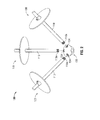
- FIG. 1 is a perspective view of a surgical support assembly including three support members, three position control members, and an imaging member;
- FIG. 2 is a partial assembly view of the surgical support assembly as shown in FIG. 1 , with the support members inserted through the position control members and separate from the imaging member;
- FIG. 3A is a side cross-sectional view of a position control member before a support member is inserted therethrough;
- FIG. 3B shows the side cross-sectional view of FIG. 3A , with a support member partially inserted therethrough and pivoted relative to the position control member;
- FIG. 3C shows the side cross-sectional view of FIG. 3A , with a support member fully inserted therethrough at an angle and locked into position;
- FIG. 3D shows the side cross-sectional view of FIG. 3C , further including a passageway through which a set screw may directly engage the support member;
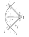
- FIG. 4 is a cross-sectional view of the surgical support assembly of FIG. 1 , fully assembled and disposed in a body cavity;
- FIG. 5 is a side perspective view of an embodiment of a position control member as a flat pad, with a support member inserted therethrough;
- FIG. 6 is a side cross-sectional view of partial assembly view of a surgical support assembly having two support members, with one support member securely attached to the imaging element with an interference fit, and another support member inserted into position in the body cavity prior to attachment to the imaging element; and
- FIG. 7 is a bottom perspective view of an embodiment of a surgical support assembly having an imaging element incorporating a projector to display an image inside a body cavity.
- proximal will refer to the portion of the assembly closest to the operator
- distal will refer to the portion of the assembly farthest from the operator.
- the surgical support assembly 100 includes a plurality of support members 110 that penetrate a layer of tissue 500 ( FIG. 4 ).
- the support members may have tips configured and dimensioned to cut through tissue (not shown), or may be inserted into pre-formed incisions in tissue.
- the support members 110 are generally elongate members that have a cylindrical cross-sectional profile. Other shapes with different cross-sectional profiles are contemplated for the support members 110.
- the support members 110 may be solid or hollow.
- Position control members 120 generally include a flat underside 120b that contacts a body surface 500a ( FIG. 4 ). Underside 120b of position control members 120 may be otherwise shaped or curved to accommodate a variety of body surface conditions. Position control members 120 also include a receiving portion 122 that may be a neck or other protruding shape from the flat profile of position control member 120. At the proximal end 120a of the position control member 120 is an aperture 120c ( FIG. 3A ) that defines a passage 120d ( FIG. 3A ) through the position control member 120 through which a support member 110 may be inserted.
- Position control members 120 may also include a locking mechanism 124 that affects movement of the support members 110 at least axially through the position control member 120 and layer of tissue 500. Locking mechanisms 124 can be used to maintain position control members 124 at a desired depth in a layer of tissue 500.
- the position control members 120 may also control the degree to which the support members 110 are free to pivot relative to the position control members 120, as will be described further below.
- Imaging member 130 Attached to the distal portions 110a ( FIG. 2 ) of the support members 110 is an imaging member 130.
- Imaging member 130 may have a pod-like shape as shown, though other shapes and profiles are contemplated for imaging member 130.
- the imaging member 130 incorporates an imaging aperture 132 (shown in phantom view) for collecting or projecting images in an internal body cavity 500b ( FIG. 4 ).
- the imaging aperture 132 may be include a camera, a light pipe with polished ends, a fiber optic element, or a projector.
- the imaging member 130 is attached at the distal portions 110a of the support members 110 such that it forms an apex of the support members 110.
- the imaging aperture 132 is disposed on or embedded in a side surface of imaging member 130 such that it has a substantially unobstructed view of a surgical site.
- the positioning of the support members 110 and the imaging member 130 may also be inverted such that the imaging member is at a distal vertex and the imaging member looks proximally toward the abdominal wall, for example in a hernia operation.
- FIG. 2 the surgical support assembly 100 is shown partially assembled, with the support members 110 inserted through the position control members 120, but separate from the imaging member 130.
- the imaging member 130 contains threaded receiving apertures 134 and the distal portions 110a of the support members 110 are threaded such that the support members 110 and the imaging member 130 threadably engage upon inserting and rotating the support members 110 into the respective threaded receiving apertures 134.
- the support members 110 and the imaging element 130 may be attached with a press or interference fit, a spline configuration, or a bayonet-type connection.
- support members 110 may be considerably more slender than than depicted, for example the members may be 2-5mm in diameter allowing for small incisions or needle like placement of the members.
- Imaging element 130 may be placed through a separate larger incision or trocar intended as the primary surgical incision. Thus, a separate incision for visualization is not necessary and the risk of incisional hernia is reduced.
- position control member 110 may include a rotatable element 126, which rotates, pivots or otherwise moves within receiving portion 122.
- Rotatable element 126 may be seated in position control member 120 in a ball-and-socket configuration.
- Other configurations are contemplated to allow support members 110 to pivot within position control members 120, such as a movable structure of rods, levers, and/or cuffs.
- Rotatable element 126 may also extend into the position control member 120 below the receiving portion 122.
- Rotatable element 126 includes a passage 126a therethrough that aligns with the passage 120d through the receiving member 122. Adjacent to the rotatable member 126 is locking mechanism 124, which is shown as a screw 124a that advances through a threaded passage 122a in a portion of receiving member 122. Other locking mechanisms are contemplated for use in the position control member 120, such as a knob or button lock, or a clamping collar.
- FIG. 3B a support member 110 is shown partially inserted through the passage 120d and the passage 126a.
- Rotatable member 126 allows for support member 110 to pivot within position control member 120.
- the position control member 120 is in an unlocked position, as shown with the screw 124a backed out of the threaded passage 122a. With the screw 124a spaced from the rotatable member 126 and support member 110, the screw 124a does not inhibit the motion of support member 110 through the position control member 120.
- the position control member 120 is shown in a locked position, with the screw 124a advanced through the threaded passage 122a and in contact with the rotatable member 126.
- the screw 124a frictionally engages the outer surface of rotatable member 126, support member 110, inserted therethrough, is prevented from further pivoting within the passage 120d.
- the rotatable member 126 may exert a compressive force on the support member 110 disposed through the passage 126a, inhibiting it from further translating axially through the position control member 120.
- the rotatable member 126 may also include a passage 126b through which the screw 124a may advance to directly contact the support member 110.
- the screw 124a is advanced through passage 126b until direct contact with support member 110 is made, and maintains the desired depth of insertion of the support member 110 through the passages 120d, 126a.
- the screw 124a also prevents the support member 110 from pivoting relative to the position control member 120 by bracing it against the passages 120d, 126a.
- the passage 126a may be dimensioned such that the support member 110 frictionally engages the rotatable member 126 upon insertion.
- the frictional engagement of the support member 110 and rotatable member 126 ensure that the support member is maintained at a desired depth in the body cavity 500b.
- the axial depth of the support member 110 may be changed by additional forces exerted by an operator.
- position control member 120 may incorporate a separate locking mechanism to inhibit the axial translation of support member 110 (not shown).
- FIG. 4 a full assembly view of surgical access assembly 100 is shown.
- an operator will place position control members 120 on a body surface 500a to designate the points of insertion for the support members 110 through a tissue layer 500.
- the support members 110 are then inserted into the respective position control members 120, through the tissue layer 500, and into a body cavity 500b.
- Support members 110 are positioned to a desired axial depth and pivoted to a desired degree within position control members 120.
- Imaging member 130 is inserted through the layer of tissue 500 either through a separate incision, or an appropriately sized incision through which one of the support members 110 may also be inserted.
- Graspers, forceps, or other instruments may be used to hold the imaging member 130 in place in the body cavity 500b prior to assembly of the surgical support assembly 100.
- the threaded distal portions 110a of the support members 110 are then attached to the threaded receiving apertures 134 of the imaging member 130.
- the position control members 120 With the imaging member 130 positioned above the surgical site in the internal body cavity 500b, the position control members 120 are locked such that the support members 110 are maintained in their desired axial and angular positions. Locking of the position control members 120 is accomplished by advancing the set screw 124a through the threaded passage 122a.
- the imaging aperture 132 of the imaging member 130 is then securely positioned to collect images from the surgical site below.
- the position control members 120 are unlocked, and the support members may be detached from the imaging member 130 and removed from the tissue layer 500 and the position control members 120.
- the imaging member 130 then may also be removed from the body cavity 500b and the position control members 120 removed from the body surface 500a.
- Position control member 220 is shown with a support member 110 inserted therethrough.
- Position control member 220 is shown as a flat pad to be disposed on a body surface 500a. Any number of shapes and layered configurations are contemplated for position control member 220.
- Position control member 220 may additionally be treated with an adhesive on its underside 220b (not shown) to aid in the attachment of position control member 220 to a body surface 500a (not shown).
- Position control member 220 is formed of a material suitable to frictionally engage an outer surface of support member 110 when the support member 110 is inserted therethrough, such as fabric or rubber.
- Position control member 110 may be formed of various thicknesses to provide a desired degree of position control.
- Surgical access assembly 300 includes at least two support members 310.
- Support members 310 are substantially similar to support members 110 of the previous embodiments, but support members 310 contain a passage 310a extending the length of support member 310 through which equipment such as wires 336 may be passed.
- Wires may supply power or control signals to an imaging element 330 or may send or receive images between the imaging element 330 and another device.
- Surgical access assembly 300 also incorporates position control members 320.
- Position control members 320 are substantially similar to position control members 120 discussed above, but do not include a rotatable member. Position control members 320 are disposed on a body surface 500a such that the support members 110 are inserted at desired angles relative to a body cavity 500b. Surgical access assembly 300 may be utilized on surgical sites with uneven or irregular body surface geometries.
- Position control members 320 include a receiving portion 322 extending from the flat profile of the position control member 320. The receiving portion 322 defines a passage 322a through which the support member 310 is inserted.
- a support member 310 may frictionally engage a position control member 320, or may be free to translate within the passage 322a.
- a latching member 324 may be present to lock the support member 310 in position in the position control member 320.
- the latching member 324 is a lever that rotates and causes an end 324b to frictionally engages an outer surface of the support member 310.
- Surgical access assembly 300 includes imaging member 330.
- Imaging member 330 includes an imaging aperture 332 and receiving apertures 334. Distal portions 310b of support members 310 frictionally fit within receiving apertures 334.
- Other couplings between support members 310 and imaging member 330 are contemplated, including a threaded connection, tongue-and-groove connection, or bayonet-type coupling.
- Surgical access assembly 400 incorporates support members 110, position control members 120, and an imaging member 430.
- Imaging member 430 incorporates an imaging aperture 432, and an image projecting element 436.
- Image projecting element 436 projects an image collected from imaging aperture 430 onto a portion of body cavity 500b. The projected image may be projected laterally, proximally or distally to display on any suitable surface in the body cavity 500b such as a tissue wall, on an implant, such as a hernia mesh or on a separate screen inserted into the body cavity 500b (not shown).
- the projected image allows an operator or surgeon to view the received image from a surgical site in situations where the field of view for an operator might be obscured, but where the image receiving element 432 is able to access.
- the image projecting element 436 may project images other than those from the image receiving element 432, such as images stored in memory or those externally transmitted to the imaging element 430.
- he projected image may provide a target or project a preplanned template for an eventual configuration of tissue or project a go/no-go region.
- equipment such as wires or fiber optic cables may serve as position control members, and suspend an imaging member above a body cavity for use during minimally invasive procedures.
- a position control member may be inserted into a body cavity, extend through the body cavity, and exit a portion of the body cavity, with an imaging member mounted to the portion of the position control member mounted in the body cavity.
Landscapes
- Health & Medical Sciences (AREA)
- Life Sciences & Earth Sciences (AREA)
- Surgery (AREA)
- Biomedical Technology (AREA)
- Medical Informatics (AREA)
- Optics & Photonics (AREA)
- Pathology (AREA)
- Radiology & Medical Imaging (AREA)
- Biophysics (AREA)
- Engineering & Computer Science (AREA)
- Physics & Mathematics (AREA)
- Heart & Thoracic Surgery (AREA)
- Nuclear Medicine, Radiotherapy & Molecular Imaging (AREA)
- Molecular Biology (AREA)
- Animal Behavior & Ethology (AREA)
- General Health & Medical Sciences (AREA)
- Public Health (AREA)
- Veterinary Medicine (AREA)
- Surgical Instruments (AREA)
- Endoscopes (AREA)
Abstract
Description
- The present application claims the benefit of and priority to
U.S. Provisional Application Serial No. 61/602,103, filed on February 23, 2012 - This application generally relates to the field of minimally invasive procedures. More particularly, the present disclosure relates to a surgical support assembly for positioning and securing a camera or projector inside the body in the proximity of a surgical site.
- Today, many surgical procedures are performed through small incisions in the skin, as compared to the larger incisions typically required in traditional procedures, in an effort to reduce both trauma to the patient and recovery time. Generally, such procedures are referred to as endoscopic, unless performed on the patient's abdomen, in which case the procedure is referred to as laparoscopic. Throughout the present disclosure, the term minimally invasive should be understood to encompass both endoscopic and laparoscopic procedures. During a typical minimally invasive procedure, surgical objects, such as surgical access ports (e.g., trocar and/or cannula assemblies), endoscopes, or other instruments, are inserted into the patient's body through the incision in tissue. Prior to the introduction of the surgical object into the patient's body, insufflation gases may be used to enlarge the area surrounding the target surgical site to create a larger, more accessible work area.
- As surgical objects are inserted into the patient's body, the problem of visibility of the insufflated workspace arises. Due to the nature of minimally invasive procedures, the relatively small incisions into tissue do not afford an operator much direct visibility into an insufflated workspace. Surgical imaging equipment is thus increasingly relied upon to visualize an insufflated workspace during minimally invasive procedures.
- However, the presence of multiple tissue layers and surgical objects can obscure the field of view for an operator using surgical imaging equipment inserted through tissue. Further, imaging equipment that is inserted into a body cavity may be forced out of alignment due to the interactions of surgical objects and tissue within the insufflated workspace. Therefore, it is desirable to have imaging equipment that can be attached to a portion of a body cavity to view a surgical site above or below the equipment. Accordingly, a need exists for a device that can support imaging equipment in an insufflated workspace with the ability to adapt to changing conditions at the minimally invasive surgical site.
- The present disclosure is directed toward a support assembly for an imaging member above a surgical site. The support assembly includes a plurality of support members that penetrate a layer of tissue and extend into a body cavity below. The support members may be rigid or resilient rods having a variety of shapes and cross-sectional profiles. In embodiments, the support members may be hollow to receive wires or other equipment.
- Disposed on the surface of the layer of tissue through which the support members are inserted are position control members which control the depth of insertion of the support members. The position control members are generally flat members that receive the support members. The position control members may additionally control the degree to which the support members may be pivoted within the position control members. In embodiments, the position control members may include a rotatable member or other structure to assist the support members in pivoting relative to the position control member.
- In other embodiments, the position control members may be flat pads through which the support members are inserted. The flat pads frictionally engage the outer surface of the support members and inhibit the amount of axial translation of the support members into an internal body cavity.
- The position control members may incorporate a locking mechanism to secure the support members in place. The locking member may be a set screw or a latching element that engages a side surface of a support member to hold the support member in place to inhibit axial translation of the support member and may additionally inhibit the support member from pivoting within the position control member. In embodiments, separate locking mechanisms may be present for inhibiting axial translation and pivoting of the support members.
- An imaging member, which may include a camera, a projector or an illuminator or a combination thereof, is attached at the distal portions of the support members to at a vertex of the support members. The secure attachment of the imaging element to the support members may include a threaded connection. In other embodiments, the coupling of the imaging member to the support members may be formed with an interference fit, tongue-and-groove, or bayonet-type connection. The imaging member collects images from the surgical site below. In embodiments, the imaging element may incorporate a projector, with collected or stored images projected onto a surface such as the interior surface of a tissue wall.
- These and other embodiments of the present disclosure will be described in greater detail below with reference to the appended figures.
- The accompanying drawings, which are incorporated in and form part of the specification, illustrate the present disclosure when viewed with reference to the description, wherein:
-
FIG. 1 is a perspective view of a surgical support assembly including three support members, three position control members, and an imaging member; -
FIG. 2 is a partial assembly view of the surgical support assembly as shown inFIG. 1 , with the support members inserted through the position control members and separate from the imaging member; -
FIG. 3A is a side cross-sectional view of a position control member before a support member is inserted therethrough; -
FIG. 3B shows the side cross-sectional view ofFIG. 3A , with a support member partially inserted therethrough and pivoted relative to the position control member; -
FIG. 3C shows the side cross-sectional view ofFIG. 3A , with a support member fully inserted therethrough at an angle and locked into position; -
FIG. 3D shows the side cross-sectional view ofFIG. 3C , further including a passageway through which a set screw may directly engage the support member; -
FIG. 4 is a cross-sectional view of the surgical support assembly ofFIG. 1 , fully assembled and disposed in a body cavity; -
FIG. 5 is a side perspective view of an embodiment of a position control member as a flat pad, with a support member inserted therethrough; -
FIG. 6 is a side cross-sectional view of partial assembly view of a surgical support assembly having two support members, with one support member securely attached to the imaging element with an interference fit, and another support member inserted into position in the body cavity prior to attachment to the imaging element; and -
FIG. 7 is a bottom perspective view of an embodiment of a surgical support assembly having an imaging element incorporating a projector to display an image inside a body cavity. - Other features of the present disclosure will become apparent from the following detailed description taken in conjunction with the accompanying drawings, which illustrate, by way of example, the principles of the present disclosure.
- The present disclosure will now describe in detail embodiments of a surgical support assembly with reference to the drawings in which like reference numerals designate identical or substantially similar parts in each view. Throughout the description, the term "proximal" will refer to the portion of the assembly closest to the operator, whereas the term "distal" will refer to the portion of the assembly farthest from the operator.
- Referring initially to
FIG. 1 , asurgical support assembly 100 is shown fully assembled. Thesurgical support assembly 100 includes a plurality ofsupport members 110 that penetrate a layer of tissue 500 (FIG. 4 ). The support members may have tips configured and dimensioned to cut through tissue (not shown), or may be inserted into pre-formed incisions in tissue. Thesupport members 110 are generally elongate members that have a cylindrical cross-sectional profile. Other shapes with different cross-sectional profiles are contemplated for thesupport members 110. Thesupport members 110 may be solid or hollow. - The
support members 110 are inserted through respectiveposition control members 120.Position control members 120 generally include aflat underside 120b that contacts abody surface 500a (FIG. 4 ).Underside 120b ofposition control members 120 may be otherwise shaped or curved to accommodate a variety of body surface conditions.Position control members 120 also include a receivingportion 122 that may be a neck or other protruding shape from the flat profile ofposition control member 120. At theproximal end 120a of theposition control member 120 is anaperture 120c (FIG. 3A ) that defines apassage 120d (FIG. 3A ) through theposition control member 120 through which asupport member 110 may be inserted. -
Position control members 120 may also include alocking mechanism 124 that affects movement of thesupport members 110 at least axially through theposition control member 120 and layer oftissue 500. Lockingmechanisms 124 can be used to maintainposition control members 124 at a desired depth in a layer oftissue 500. Theposition control members 120 may also control the degree to which thesupport members 110 are free to pivot relative to theposition control members 120, as will be described further below. - Attached to the
distal portions 110a (FIG. 2 ) of thesupport members 110 is animaging member 130.Imaging member 130 may have a pod-like shape as shown, though other shapes and profiles are contemplated for imagingmember 130. Theimaging member 130 incorporates an imaging aperture 132 (shown in phantom view) for collecting or projecting images in aninternal body cavity 500b (FIG. 4 ). Theimaging aperture 132 may be include a camera, a light pipe with polished ends, a fiber optic element, or a projector. Theimaging member 130 is attached at thedistal portions 110a of thesupport members 110 such that it forms an apex of thesupport members 110. Theimaging aperture 132 is disposed on or embedded in a side surface ofimaging member 130 such that it has a substantially unobstructed view of a surgical site. The positioning of thesupport members 110 and theimaging member 130 may also be inverted such that the imaging member is at a distal vertex and the imaging member looks proximally toward the abdominal wall, for example in a hernia operation. - Turning to
FIG. 2 , thesurgical support assembly 100 is shown partially assembled, with thesupport members 110 inserted through theposition control members 120, but separate from theimaging member 130. Theimaging member 130 contains threaded receivingapertures 134 and thedistal portions 110a of thesupport members 110 are threaded such that thesupport members 110 and theimaging member 130 threadably engage upon inserting and rotating thesupport members 110 into the respective threaded receivingapertures 134. It is also contemplated that thesupport members 110 and theimaging element 130 may be attached with a press or interference fit, a spline configuration, or a bayonet-type connection. It should be noted thatsupport members 110 may be considerably more slender than than depicted, for example the members may be 2-5mm in diameter allowing for small incisions or needle like placement of the members.Imaging element 130 may be placed through a separate larger incision or trocar intended as the primary surgical incision. Thus, a separate incision for visualization is not necessary and the risk of incisional hernia is reduced.. - Referring to
FIGS. 3A-3C , insertion of asupport member 110 into aposition control member 120 and the subsequent locking in position of asupport member 110 is shown. As seen in the cross-sectional view ofFIG. 3A ,position control member 110 may include arotatable element 126, which rotates, pivots or otherwise moves within receivingportion 122.Rotatable element 126 may be seated inposition control member 120 in a ball-and-socket configuration. Other configurations are contemplated to allowsupport members 110 to pivot withinposition control members 120, such as a movable structure of rods, levers, and/or cuffs.Rotatable element 126 may also extend into theposition control member 120 below the receivingportion 122.Rotatable element 126 includes apassage 126a therethrough that aligns with thepassage 120d through the receivingmember 122. Adjacent to therotatable member 126 is lockingmechanism 124, which is shown as ascrew 124a that advances through a threadedpassage 122a in a portion of receivingmember 122. Other locking mechanisms are contemplated for use in theposition control member 120, such as a knob or button lock, or a clamping collar. - Turning now to
FIG. 3B , asupport member 110 is shown partially inserted through thepassage 120d and thepassage 126a.Rotatable member 126 allows forsupport member 110 to pivot withinposition control member 120. As thesupport member 110 is free to translate through thepassages passage 120d, theposition control member 120 is in an unlocked position, as shown with thescrew 124a backed out of the threadedpassage 122a. With thescrew 124a spaced from therotatable member 126 andsupport member 110, thescrew 124a does not inhibit the motion ofsupport member 110 through theposition control member 120. - Referring to
FIG. 3C , theposition control member 120 is shown in a locked position, with thescrew 124a advanced through the threadedpassage 122a and in contact with therotatable member 126. As thescrew 124a frictionally engages the outer surface ofrotatable member 126,support member 110, inserted therethrough, is prevented from further pivoting within thepassage 120d. Therotatable member 126 may exert a compressive force on thesupport member 110 disposed through thepassage 126a, inhibiting it from further translating axially through theposition control member 120. - As shown in
FIG. 3D , therotatable member 126 may also include apassage 126b through which thescrew 124a may advance to directly contact thesupport member 110. Thescrew 124a is advanced throughpassage 126b until direct contact withsupport member 110 is made, and maintains the desired depth of insertion of thesupport member 110 through thepassages screw 124a also prevents thesupport member 110 from pivoting relative to theposition control member 120 by bracing it against thepassages - Alternatively, the
passage 126a may be dimensioned such that thesupport member 110 frictionally engages therotatable member 126 upon insertion. The frictional engagement of thesupport member 110 androtatable member 126 ensure that the support member is maintained at a desired depth in thebody cavity 500b. The axial depth of thesupport member 110 may be changed by additional forces exerted by an operator. Still further,position control member 120 may incorporate a separate locking mechanism to inhibit the axial translation of support member 110 (not shown). - Turning now to
FIG. 4 , a full assembly view ofsurgical access assembly 100 is shown. In use, an operator will placeposition control members 120 on abody surface 500a to designate the points of insertion for thesupport members 110 through atissue layer 500. Thesupport members 110 are then inserted into the respectiveposition control members 120, through thetissue layer 500, and into abody cavity 500b.Support members 110 are positioned to a desired axial depth and pivoted to a desired degree withinposition control members 120.Imaging member 130 is inserted through the layer oftissue 500 either through a separate incision, or an appropriately sized incision through which one of thesupport members 110 may also be inserted. Graspers, forceps, or other instruments may be used to hold theimaging member 130 in place in thebody cavity 500b prior to assembly of thesurgical support assembly 100. The threadeddistal portions 110a of thesupport members 110 are then attached to the threaded receivingapertures 134 of theimaging member 130. With theimaging member 130 positioned above the surgical site in theinternal body cavity 500b, theposition control members 120 are locked such that thesupport members 110 are maintained in their desired axial and angular positions. Locking of theposition control members 120 is accomplished by advancing theset screw 124a through the threadedpassage 122a. Theimaging aperture 132 of theimaging member 130 is then securely positioned to collect images from the surgical site below. When minimally invasive procedures are completed, theposition control members 120 are unlocked, and the support members may be detached from theimaging member 130 and removed from thetissue layer 500 and theposition control members 120. Theimaging member 130 then may also be removed from thebody cavity 500b and theposition control members 120 removed from thebody surface 500a. - Referring to
FIG. 5 , an embodiment of aposition control member 220 is shown with asupport member 110 inserted therethrough.Position control member 220 is shown as a flat pad to be disposed on abody surface 500a. Any number of shapes and layered configurations are contemplated forposition control member 220.Position control member 220 may additionally be treated with an adhesive on its underside 220b (not shown) to aid in the attachment ofposition control member 220 to abody surface 500a (not shown).Position control member 220 is formed of a material suitable to frictionally engage an outer surface ofsupport member 110 when thesupport member 110 is inserted therethrough, such as fabric or rubber. The frictional engagement ofposition control member 220 andsupport member 110 allows an operator to position thesupport member 110 at a desired depth, without unintended axial translation of thesupport member 110. This position control also maintains the angular position at which thesupport member 110 is inserted though the layer oftissue 500.Position control member 110 may be formed of various thicknesses to provide a desired degree of position control. - Turning now to
FIG. 6 , a partial assembly view of an embodiment of asurgical access assembly 300 is shown.Surgical access assembly 300 includes at least twosupport members 310.Support members 310 are substantially similar to supportmembers 110 of the previous embodiments, butsupport members 310 contain apassage 310a extending the length ofsupport member 310 through which equipment such aswires 336 may be passed. Wires may supply power or control signals to animaging element 330 or may send or receive images between theimaging element 330 and another device. -
Surgical access assembly 300 also incorporatesposition control members 320.Position control members 320 are substantially similar to position controlmembers 120 discussed above, but do not include a rotatable member.Position control members 320 are disposed on abody surface 500a such that thesupport members 110 are inserted at desired angles relative to abody cavity 500b.Surgical access assembly 300 may be utilized on surgical sites with uneven or irregular body surface geometries.Position control members 320 include a receivingportion 322 extending from the flat profile of theposition control member 320. The receivingportion 322 defines apassage 322a through which thesupport member 310 is inserted. Asupport member 310 may frictionally engage aposition control member 320, or may be free to translate within thepassage 322a. A latchingmember 324 may be present to lock thesupport member 310 in position in theposition control member 320. The latchingmember 324 is a lever that rotates and causes anend 324b to frictionally engages an outer surface of thesupport member 310. -
Surgical access assembly 300 includesimaging member 330.Imaging member 330 includes animaging aperture 332 and receivingapertures 334.Distal portions 310b ofsupport members 310 frictionally fit within receivingapertures 334. Other couplings betweensupport members 310 andimaging member 330 are contemplated, including a threaded connection, tongue-and-groove connection, or bayonet-type coupling. With thesupport members 310 securely attached to theimaging member 330, theimaging aperture 332 facesbody cavity 500b such that it can collect images from a surgical site below. - Referring to
FIG. 7 , an embodiment of asurgical access assembly 400 is shown.Surgical access assembly 400 incorporatessupport members 110,position control members 120, and animaging member 430.Imaging member 430 incorporates animaging aperture 432, and animage projecting element 436.Image projecting element 436 projects an image collected fromimaging aperture 430 onto a portion ofbody cavity 500b. The projected image may be projected laterally, proximally or distally to display on any suitable surface in thebody cavity 500b such as a tissue wall, on an implant, such as a hernia mesh or on a separate screen inserted into thebody cavity 500b (not shown). The projected image allows an operator or surgeon to view the received image from a surgical site in situations where the field of view for an operator might be obscured, but where theimage receiving element 432 is able to access. Alternatively, theimage projecting element 436 may project images other than those from theimage receiving element 432, such as images stored in memory or those externally transmitted to theimaging element 430. For example, he projected image may provide a target or project a preplanned template for an eventual configuration of tissue or project a go/no-go region. - In further embodiments, equipment such as wires or fiber optic cables may serve as position control members, and suspend an imaging member above a body cavity for use during minimally invasive procedures. In still further embodiments, a position control member may be inserted into a body cavity, extend through the body cavity, and exit a portion of the body cavity, with an imaging member mounted to the portion of the position control member mounted in the body cavity.
- It will be understood that various modifications may be made to the embodiments disclosed herein. Therefore, the above description should not be construed as limiting, but merely as exemplifications of embodiments. Those skilled in the art will envision other modifications within the scope and spirit of the present disclosure.
- The invention may be described by reference to the following numbered paragraphs:-
- 1. A surgical support assembly, comprising:
- a plurality of tissue penetrating support members;
- a plurality of position controlling members, each tissue penetrating support member inserted through a position controlling member; and
- an imaging member attached at the vertex of the plurality of tissue penetrating support members.
- 2. The surgical support assembly of paragraph 1, wherein at least one of the tissue penetrating support members is a rod.
- 3. The surgical support assembly of paragraph 1, wherein at least one of the plurality of tissue penetrating support members has a passage therethrough.
- 4. The surgical support assembly of paragraph 3, wherein objects are inserted through the passage.
- 5. The surgical support assembly of paragraph 1, wherein at least one of the plurality of position control members includes a rotatable member through which the tissue penetrating support member is inserted.
- 6. The surgical support assembly of paragraph 1, wherein at least one of the plurality of position control members includes a lock for maintaining the position of a tissue penetrating support member relative to the position control member.
- 7. The surgical support assembly of paragraph 1, wherein the imaging element includes a camera.
- 8. The surgical support assembly of paragraph 1, wherein the imaging element includes a projector.
- 9. The surgical support assembly of paragraph 1, wherein the imaging element includes an aperture for receiving a tissue penetrating support member.
- 10. A method of fixing an imaging element in a body cavity, comprising:
- selecting a site through which to assembly a surgical support assembly, the surgical support assembly comprising;
- a plurality of tissue penetrating support members;
- a plurality of position controlling members, each tissue penetrating support member inserted through a position controlling member; and
- an imaging member attached at the vertex of the plurality of tissue penetrating support members;
- inserting a plurality of tissue penetrating support members each through a position control member, through tissue, and into an internal body cavity below;
- attaching an imaging element at the vertex of the plurality of tissue penetrating support members in the internal body cavity.
- selecting a site through which to assembly a surgical support assembly, the surgical support assembly comprising;
- 11. The method of paragraph 10, wherein at least one of the tissue penetrating support members is a rod.
- 12. The method of paragraph 10, wherein at least one of the plurality of tissue penetrating support members has a passage therethrough.
- 13. The method of paragraph 12, wherein objects are inserted through the passage.
- 14. The method of paragraph 10, wherein at least one of the plurality of position control members includes a rotatable member through which the tissue penetrating support member is inserted.
- 15. The method of paragraph 10 wherein at least one of the plurality of position control members includes a lock for maintaining the position of a tissue penetrating support member relative to the position control member.
- 16. The method of paragraph 10, further including positioning at least one tissue penetrating support member through a position control member and disposing it at an angle relative to the position control member.
- 17. The method of paragraph 16, further including locking the at least one tissue penetrating support member relative to the position control member.
- 18. The method of paragraph 10, wherein the imaging element receives images.
- 19. The method of paragraph 10, wherein the imaging element projects images.
- 20. The method of paragraph 10, wherein the imaging element includes an aperture for receiving a tissue penetrating support member.
Claims (14)
- A surgical support assembly, comprising:a plurality of tissue penetrating support members;a plurality of position controlling members, each tissue penetrating support member inserted through a position controlling member; andan imaging member attached at the vertex of the plurality of tissue penetrating support members.
- The surgical support assembly of claim 1, wherein at least one of the tissue penetrating support members is a rod.
- The surgical support assembly of claim 1 or claim 2, wherein at least one of the plurality of tissue penetrating support members has a passage therethrough, preferably wherein objects are inserted through the passage.
- The surgical support assembly of any preceding claim, wherein at least one of the plurality of position control members includes a rotatable member through which the tissue penetrating support member is inserted; and/or wherein at least one of the plurality of position control members includes a lock for maintaining the position of a tissue penetrating support member relative to the position control member.
- The surgical support assembly of any preceding claim, wherein the imaging element includes a camera.
- The surgical support assembly of any preceding claim, wherein the imaging element includes a projector.
- The surgical support assembly of any preceding claim, wherein the imaging element includes an aperture for receiving a tissue penetrating support member.
- A method of fixing an imaging element in a body cavity, comprising:selecting a site through which to assembly a surgical support assembly, the surgical support assembly comprising;a plurality of tissue penetrating support members;a plurality of position controlling members, each tissue penetrating support member inserted through a position controlling member; andan imaging member attached at the vertex of the plurality of tissue penetrating support members;inserting a plurality of tissue penetrating support members each through a position control member, through tissue, and into an internal body cavity below;attaching an imaging element at the vertex of the plurality of tissue penetrating support members in the internal body cavity.
- The method of claim 8, wherein at least one of the tissue penetrating support members is a rod; and/or wherein at least one of the plurality of tissue penetrating support members has a passage therethrough; preferably wherein objects are inserted through the passage.
- The method of claim 8 or claim 9, wherein at least one of the plurality of position control members includes a rotatable member through which the tissue penetrating support member is inserted.
- The method of any of claims 8 to 10 wherein at least one of the plurality of position control members includes a lock for maintaining the position of a tissue penetrating support member relative to the position control member.
- The method of any of claims 8 to 11, further including positioning at least one tissue penetrating support member through a position control member and disposing it at an angle relative to the position control member, preferably further still including locking the at least one tissue penetrating support member relative to the position control member.
- The method of any of claims 8 to 12, wherein the imaging element receives images; and/or wherein the imaging element projects images.
- The method of any of claims 8 to 13, wherein the imaging element includes an aperture for receiving a tissue penetrating support member.
Applications Claiming Priority (2)
| Application Number | Priority Date | Filing Date | Title |
|---|---|---|---|
| US201261602103P | 2012-02-23 | 2012-02-23 | |
| US13/758,156 US20130225920A1 (en) | 2012-02-23 | 2013-02-04 | Surgical support assembly |
Publications (2)
| Publication Number | Publication Date |
|---|---|
| EP2630906A1 true EP2630906A1 (en) | 2013-08-28 |
| EP2630906B1 EP2630906B1 (en) | 2018-10-31 |
Family
ID=47826906
Family Applications (1)
| Application Number | Title | Priority Date | Filing Date |
|---|---|---|---|
| EP13156287.8A Not-in-force EP2630906B1 (en) | 2012-02-23 | 2013-02-22 | Surgical support assembly |
Country Status (4)
| Country | Link |
|---|---|
| US (1) | US20130225920A1 (en) |
| EP (1) | EP2630906B1 (en) |
| AU (1) | AU2013200888A1 (en) |
| CA (1) | CA2805207A1 (en) |
Families Citing this family (3)
| Publication number | Priority date | Publication date | Assignee | Title |
|---|---|---|---|---|
| EP2842511A1 (en) * | 2013-08-27 | 2015-03-04 | Vantage Surgical Systems, Inc. | Method for minimally invasive surgery stereoscopic visualization |
| WO2016129169A1 (en) * | 2015-02-10 | 2016-08-18 | シャープ株式会社 | In-vivo monitoring camera system |
| SE541821C2 (en) * | 2017-11-27 | 2019-12-27 | Clinical Laserthermia Systems Ab | Surgical probe positioning device |
Citations (4)
| Publication number | Priority date | Publication date | Assignee | Title |
|---|---|---|---|---|
| US20070255100A1 (en) * | 2006-01-06 | 2007-11-01 | Olympus Medical Systems Corporation | Medical method and medical system conducted percutaneous or using naturally occurring body orifice |
| US20080309758A1 (en) * | 2007-06-14 | 2008-12-18 | Olympus Medical Systems Corp. | Endoscope system, camera set on body cavity inner wall and method of setting the camera set on body cavity inner wall on inner surface of body cavity wall |
| US20100152539A1 (en) * | 2008-12-17 | 2010-06-17 | Ethicon Endo-Surgery, Inc. | Positionable imaging medical devices |
| US20110257488A1 (en) * | 2008-10-31 | 2011-10-20 | Limited Liability Company Japan Medical Creative | Surgical lighting system |
Family Cites Families (19)
| Publication number | Priority date | Publication date | Assignee | Title |
|---|---|---|---|---|
| US5361752A (en) * | 1991-05-29 | 1994-11-08 | Origin Medsystems, Inc. | Retraction apparatus and methods for endoscopic surgery |
| US5865728A (en) * | 1991-05-29 | 1999-02-02 | Origin Medsystems, Inc. | Method of using an endoscopic inflatable lifting apparatus to create an anatomic working space |
| US5375588A (en) * | 1992-08-17 | 1994-12-27 | Yoon; Inbae | Method and apparatus for use in endoscopic procedures |
| US5540648A (en) * | 1992-08-17 | 1996-07-30 | Yoon; Inbae | Medical instrument stabilizer with anchoring system and methods |
| US5672168A (en) * | 1994-10-07 | 1997-09-30 | De La Torre; Roger A. | Laparoscopic access port for surgical instruments or the hand |
| US5551847A (en) * | 1995-04-24 | 1996-09-03 | Ingersoll-Rand Company | Lost motion pilot valve for diaphragm pump |
| US5817013A (en) * | 1996-03-19 | 1998-10-06 | Enable Medical Corporation | Method and apparatus for the minimally invasive harvesting of a saphenous vein and the like |
| US6099506A (en) * | 1997-09-26 | 2000-08-08 | Macoviak; John A. | Introducer and perfusion cannula |
| US6527704B1 (en) * | 1999-03-10 | 2003-03-04 | Stryker Corporation | Endoscopic camera system integrated with a trocar sleeve |
| JP2003204920A (en) * | 2002-01-11 | 2003-07-22 | Olympus Optical Co Ltd | Insertion assisting tool |
| US20100081875A1 (en) * | 2003-07-15 | 2010-04-01 | EndoRobotics Inc. | Surgical Device For Minimal Access Surgery |
| US7951117B2 (en) * | 2008-06-25 | 2011-05-31 | Tyco Healthcare Group Lp | Multi-lumen access port |
| JP4302602B2 (en) * | 2004-09-24 | 2009-07-29 | オリンパス株式会社 | Endoscopic treatment tool, endoscopic treatment system, and support adapter |
| US7851117B2 (en) * | 2005-11-28 | 2010-12-14 | Sakata Inx Corp. | Liquid developer |
| US7927272B2 (en) * | 2006-08-04 | 2011-04-19 | Avantis Medical Systems, Inc. | Surgical port with embedded imaging device |
| JP4472728B2 (en) * | 2007-06-14 | 2010-06-02 | オリンパスメディカルシステムズ株式会社 | Endoscope system |
| US20090227843A1 (en) * | 2007-09-12 | 2009-09-10 | Smith Jeffrey A | Multi-instrument access devices and systems |
| US8834358B2 (en) * | 2009-03-27 | 2014-09-16 | EndoSphere Surgical, Inc. | Cannula with integrated camera and illumination |
| US8545515B2 (en) * | 2009-09-23 | 2013-10-01 | Intuitive Surgical Operations, Inc. | Curved cannula surgical system |
-
2013
- 2013-02-04 US US13/758,156 patent/US20130225920A1/en not_active Abandoned
- 2013-02-08 CA CA2805207A patent/CA2805207A1/en not_active Abandoned
- 2013-02-14 AU AU2013200888A patent/AU2013200888A1/en not_active Abandoned
- 2013-02-22 EP EP13156287.8A patent/EP2630906B1/en not_active Not-in-force
Patent Citations (4)
| Publication number | Priority date | Publication date | Assignee | Title |
|---|---|---|---|---|
| US20070255100A1 (en) * | 2006-01-06 | 2007-11-01 | Olympus Medical Systems Corporation | Medical method and medical system conducted percutaneous or using naturally occurring body orifice |
| US20080309758A1 (en) * | 2007-06-14 | 2008-12-18 | Olympus Medical Systems Corp. | Endoscope system, camera set on body cavity inner wall and method of setting the camera set on body cavity inner wall on inner surface of body cavity wall |
| US20110257488A1 (en) * | 2008-10-31 | 2011-10-20 | Limited Liability Company Japan Medical Creative | Surgical lighting system |
| US20100152539A1 (en) * | 2008-12-17 | 2010-06-17 | Ethicon Endo-Surgery, Inc. | Positionable imaging medical devices |
Also Published As
| Publication number | Publication date |
|---|---|
| CA2805207A1 (en) | 2013-08-23 |
| AU2013200888A1 (en) | 2013-09-12 |
| US20130225920A1 (en) | 2013-08-29 |
| EP2630906B1 (en) | 2018-10-31 |
Similar Documents
| Publication | Publication Date | Title |
|---|---|---|
| EP2243435B1 (en) | Visual veress needle assembly | |
| EP2104461B1 (en) | Access sheath with removable optical penetrating member | |
| US10028652B2 (en) | Rapid laparoscopy exchange system and method of use thereof | |
| US9326761B2 (en) | Multi-lumen access port | |
| CN107361827B (en) | Optical trocar visualization system and apparatus | |
| EP3251604B1 (en) | System of deploying an elongate unit in a body cavity | |
| US7753901B2 (en) | Laparoscopic instrument and cannula assembly and related surgical method | |
| US20090036738A1 (en) | Device for creating a free transcutaneous access to an endoscopic operating area | |
| CN104042306A (en) | Reverse seam ripper dissector | |
| US9999443B2 (en) | Instrument head single loader | |
| EP2630906B1 (en) | Surgical support assembly | |
| US11612386B2 (en) | Universal surgical access system | |
| US9687270B2 (en) | Instrument system for minimally invasive surgery in single port technology | |
| KR102596872B1 (en) | Dual structure laparoscopic surgery instrument | |
| US20100262079A1 (en) | Bendable veress needle assembly | |
| US8845657B2 (en) | Surgical support assembly | |
| CN120093387A (en) | Pliers and Pliers Systems |
Legal Events
| Date | Code | Title | Description |
|---|---|---|---|
| PUAI | Public reference made under article 153(3) epc to a published international application that has entered the european phase |
Free format text: ORIGINAL CODE: 0009012 |
|
| AK | Designated contracting states |
Kind code of ref document: A1 Designated state(s): AL AT BE BG CH CY CZ DE DK EE ES FI FR GB GR HR HU IE IS IT LI LT LU LV MC MK MT NL NO PL PT RO RS SE SI SK SM TR |
|
| AX | Request for extension of the european patent |
Extension state: BA ME |
|
| 17P | Request for examination filed |
Effective date: 20140219 |
|
| RBV | Designated contracting states (corrected) |
Designated state(s): AL AT BE BG CH CY CZ DE DK EE ES FI FR GB GR HR HU IE IS IT LI LT LU LV MC MK MT NL NO PL PT RO RS SE SI SK SM TR |
|
| 17Q | First examination report despatched |
Effective date: 20160706 |
|
| STAA | Information on the status of an ep patent application or granted ep patent |
Free format text: STATUS: EXAMINATION IS IN PROGRESS |
|
| GRAP | Despatch of communication of intention to grant a patent |
Free format text: ORIGINAL CODE: EPIDOSNIGR1 |
|
| STAA | Information on the status of an ep patent application or granted ep patent |
Free format text: STATUS: GRANT OF PATENT IS INTENDED |
|
| INTG | Intention to grant announced |
Effective date: 20180613 |
|
| GRAS | Grant fee paid |
Free format text: ORIGINAL CODE: EPIDOSNIGR3 |
|
| GRAA | (expected) grant |
Free format text: ORIGINAL CODE: 0009210 |
|
| STAA | Information on the status of an ep patent application or granted ep patent |
Free format text: STATUS: THE PATENT HAS BEEN GRANTED |
|
| AK | Designated contracting states |
Kind code of ref document: B1 Designated state(s): AL AT BE BG CH CY CZ DE DK EE ES FI FR GB GR HR HU IE IS IT LI LT LU LV MC MK MT NL NO PL PT RO RS SE SI SK SM TR |
|
| REG | Reference to a national code |
Ref country code: CH Ref legal event code: EP Ref country code: GB Ref legal event code: FG4D |
|
| REG | Reference to a national code |
Ref country code: AT Ref legal event code: REF Ref document number: 1058379 Country of ref document: AT Kind code of ref document: T Effective date: 20181115 |
|
| REG | Reference to a national code |
Ref country code: DE Ref legal event code: R096 Ref document number: 602013045815 Country of ref document: DE |
|
| REG | Reference to a national code |
Ref country code: IE Ref legal event code: FG4D |
|
| REG | Reference to a national code |
Ref country code: NL Ref legal event code: MP Effective date: 20181031 |
|
| REG | Reference to a national code |
Ref country code: LT Ref legal event code: MG4D |
|
| REG | Reference to a national code |
Ref country code: AT Ref legal event code: MK05 Ref document number: 1058379 Country of ref document: AT Kind code of ref document: T Effective date: 20181031 |
|
| PG25 | Lapsed in a contracting state [announced via postgrant information from national office to epo] |
Ref country code: FI Free format text: LAPSE BECAUSE OF FAILURE TO SUBMIT A TRANSLATION OF THE DESCRIPTION OR TO PAY THE FEE WITHIN THE PRESCRIBED TIME-LIMIT Effective date: 20181031 Ref country code: AT Free format text: LAPSE BECAUSE OF FAILURE TO SUBMIT A TRANSLATION OF THE DESCRIPTION OR TO PAY THE FEE WITHIN THE PRESCRIBED TIME-LIMIT Effective date: 20181031 Ref country code: LV Free format text: LAPSE BECAUSE OF FAILURE TO SUBMIT A TRANSLATION OF THE DESCRIPTION OR TO PAY THE FEE WITHIN THE PRESCRIBED TIME-LIMIT Effective date: 20181031 Ref country code: IS Free format text: LAPSE BECAUSE OF FAILURE TO SUBMIT A TRANSLATION OF THE DESCRIPTION OR TO PAY THE FEE WITHIN THE PRESCRIBED TIME-LIMIT Effective date: 20190228 Ref country code: PL Free format text: LAPSE BECAUSE OF FAILURE TO SUBMIT A TRANSLATION OF THE DESCRIPTION OR TO PAY THE FEE WITHIN THE PRESCRIBED TIME-LIMIT Effective date: 20181031 Ref country code: HR Free format text: LAPSE BECAUSE OF FAILURE TO SUBMIT A TRANSLATION OF THE DESCRIPTION OR TO PAY THE FEE WITHIN THE PRESCRIBED TIME-LIMIT Effective date: 20181031 Ref country code: BG Free format text: LAPSE BECAUSE OF FAILURE TO SUBMIT A TRANSLATION OF THE DESCRIPTION OR TO PAY THE FEE WITHIN THE PRESCRIBED TIME-LIMIT Effective date: 20190131 Ref country code: ES Free format text: LAPSE BECAUSE OF FAILURE TO SUBMIT A TRANSLATION OF THE DESCRIPTION OR TO PAY THE FEE WITHIN THE PRESCRIBED TIME-LIMIT Effective date: 20181031 Ref country code: LT Free format text: LAPSE BECAUSE OF FAILURE TO SUBMIT A TRANSLATION OF THE DESCRIPTION OR TO PAY THE FEE WITHIN THE PRESCRIBED TIME-LIMIT Effective date: 20181031 Ref country code: NO Free format text: LAPSE BECAUSE OF FAILURE TO SUBMIT A TRANSLATION OF THE DESCRIPTION OR TO PAY THE FEE WITHIN THE PRESCRIBED TIME-LIMIT Effective date: 20190131 |
|
| PG25 | Lapsed in a contracting state [announced via postgrant information from national office to epo] |
Ref country code: AL Free format text: LAPSE BECAUSE OF FAILURE TO SUBMIT A TRANSLATION OF THE DESCRIPTION OR TO PAY THE FEE WITHIN THE PRESCRIBED TIME-LIMIT Effective date: 20181031 Ref country code: NL Free format text: LAPSE BECAUSE OF FAILURE TO SUBMIT A TRANSLATION OF THE DESCRIPTION OR TO PAY THE FEE WITHIN THE PRESCRIBED TIME-LIMIT Effective date: 20181031 Ref country code: PT Free format text: LAPSE BECAUSE OF FAILURE TO SUBMIT A TRANSLATION OF THE DESCRIPTION OR TO PAY THE FEE WITHIN THE PRESCRIBED TIME-LIMIT Effective date: 20190301 Ref country code: SE Free format text: LAPSE BECAUSE OF FAILURE TO SUBMIT A TRANSLATION OF THE DESCRIPTION OR TO PAY THE FEE WITHIN THE PRESCRIBED TIME-LIMIT Effective date: 20181031 Ref country code: RS Free format text: LAPSE BECAUSE OF FAILURE TO SUBMIT A TRANSLATION OF THE DESCRIPTION OR TO PAY THE FEE WITHIN THE PRESCRIBED TIME-LIMIT Effective date: 20181031 Ref country code: GR Free format text: LAPSE BECAUSE OF FAILURE TO SUBMIT A TRANSLATION OF THE DESCRIPTION OR TO PAY THE FEE WITHIN THE PRESCRIBED TIME-LIMIT Effective date: 20190201 |
|
| PG25 | Lapsed in a contracting state [announced via postgrant information from national office to epo] |
Ref country code: CZ Free format text: LAPSE BECAUSE OF FAILURE TO SUBMIT A TRANSLATION OF THE DESCRIPTION OR TO PAY THE FEE WITHIN THE PRESCRIBED TIME-LIMIT Effective date: 20181031 Ref country code: IT Free format text: LAPSE BECAUSE OF FAILURE TO SUBMIT A TRANSLATION OF THE DESCRIPTION OR TO PAY THE FEE WITHIN THE PRESCRIBED TIME-LIMIT Effective date: 20181031 Ref country code: DK Free format text: LAPSE BECAUSE OF FAILURE TO SUBMIT A TRANSLATION OF THE DESCRIPTION OR TO PAY THE FEE WITHIN THE PRESCRIBED TIME-LIMIT Effective date: 20181031 |
|
| REG | Reference to a national code |
Ref country code: DE Ref legal event code: R097 Ref document number: 602013045815 Country of ref document: DE |
|
| PG25 | Lapsed in a contracting state [announced via postgrant information from national office to epo] |
Ref country code: EE Free format text: LAPSE BECAUSE OF FAILURE TO SUBMIT A TRANSLATION OF THE DESCRIPTION OR TO PAY THE FEE WITHIN THE PRESCRIBED TIME-LIMIT Effective date: 20181031 Ref country code: SM Free format text: LAPSE BECAUSE OF FAILURE TO SUBMIT A TRANSLATION OF THE DESCRIPTION OR TO PAY THE FEE WITHIN THE PRESCRIBED TIME-LIMIT Effective date: 20181031 Ref country code: SK Free format text: LAPSE BECAUSE OF FAILURE TO SUBMIT A TRANSLATION OF THE DESCRIPTION OR TO PAY THE FEE WITHIN THE PRESCRIBED TIME-LIMIT Effective date: 20181031 Ref country code: RO Free format text: LAPSE BECAUSE OF FAILURE TO SUBMIT A TRANSLATION OF THE DESCRIPTION OR TO PAY THE FEE WITHIN THE PRESCRIBED TIME-LIMIT Effective date: 20181031 |
|
| PLBE | No opposition filed within time limit |
Free format text: ORIGINAL CODE: 0009261 |
|
| STAA | Information on the status of an ep patent application or granted ep patent |
Free format text: STATUS: NO OPPOSITION FILED WITHIN TIME LIMIT |
|
| REG | Reference to a national code |
Ref country code: CH Ref legal event code: PL |
|
| 26N | No opposition filed |
Effective date: 20190801 |
|
| PG25 | Lapsed in a contracting state [announced via postgrant information from national office to epo] |
Ref country code: MC Free format text: LAPSE BECAUSE OF FAILURE TO SUBMIT A TRANSLATION OF THE DESCRIPTION OR TO PAY THE FEE WITHIN THE PRESCRIBED TIME-LIMIT Effective date: 20181031 Ref country code: SI Free format text: LAPSE BECAUSE OF FAILURE TO SUBMIT A TRANSLATION OF THE DESCRIPTION OR TO PAY THE FEE WITHIN THE PRESCRIBED TIME-LIMIT Effective date: 20181031 Ref country code: LU Free format text: LAPSE BECAUSE OF NON-PAYMENT OF DUE FEES Effective date: 20190222 |
|
| REG | Reference to a national code |
Ref country code: BE Ref legal event code: MM Effective date: 20190228 |
|
| PG25 | Lapsed in a contracting state [announced via postgrant information from national office to epo] |
Ref country code: CH Free format text: LAPSE BECAUSE OF NON-PAYMENT OF DUE FEES Effective date: 20190228 Ref country code: LI Free format text: LAPSE BECAUSE OF NON-PAYMENT OF DUE FEES Effective date: 20190228 |
|
| PG25 | Lapsed in a contracting state [announced via postgrant information from national office to epo] |
Ref country code: BE Free format text: LAPSE BECAUSE OF NON-PAYMENT OF DUE FEES Effective date: 20190228 |
|
| PG25 | Lapsed in a contracting state [announced via postgrant information from national office to epo] |
Ref country code: TR Free format text: LAPSE BECAUSE OF FAILURE TO SUBMIT A TRANSLATION OF THE DESCRIPTION OR TO PAY THE FEE WITHIN THE PRESCRIBED TIME-LIMIT Effective date: 20181031 |
|
| PGFP | Annual fee paid to national office [announced via postgrant information from national office to epo] |
Ref country code: DE Payment date: 20200121 Year of fee payment: 8 Ref country code: IE Payment date: 20200123 Year of fee payment: 8 Ref country code: GB Payment date: 20200123 Year of fee payment: 8 |
|
| PG25 | Lapsed in a contracting state [announced via postgrant information from national office to epo] |
Ref country code: MT Free format text: LAPSE BECAUSE OF NON-PAYMENT OF DUE FEES Effective date: 20190222 |
|
| PGFP | Annual fee paid to national office [announced via postgrant information from national office to epo] |
Ref country code: FR Payment date: 20200122 Year of fee payment: 8 |
|
| PG25 | Lapsed in a contracting state [announced via postgrant information from national office to epo] |
Ref country code: CY Free format text: LAPSE BECAUSE OF FAILURE TO SUBMIT A TRANSLATION OF THE DESCRIPTION OR TO PAY THE FEE WITHIN THE PRESCRIBED TIME-LIMIT Effective date: 20181031 |
|
| PG25 | Lapsed in a contracting state [announced via postgrant information from national office to epo] |
Ref country code: HU Free format text: LAPSE BECAUSE OF FAILURE TO SUBMIT A TRANSLATION OF THE DESCRIPTION OR TO PAY THE FEE WITHIN THE PRESCRIBED TIME-LIMIT; INVALID AB INITIO Effective date: 20130222 |
|
| REG | Reference to a national code |
Ref country code: DE Ref legal event code: R119 Ref document number: 602013045815 Country of ref document: DE |
|
| GBPC | Gb: european patent ceased through non-payment of renewal fee |
Effective date: 20210222 |
|
| PG25 | Lapsed in a contracting state [announced via postgrant information from national office to epo] |
Ref country code: IE Free format text: LAPSE BECAUSE OF NON-PAYMENT OF DUE FEES Effective date: 20210222 Ref country code: GB Free format text: LAPSE BECAUSE OF NON-PAYMENT OF DUE FEES Effective date: 20210222 Ref country code: FR Free format text: LAPSE BECAUSE OF NON-PAYMENT OF DUE FEES Effective date: 20210228 Ref country code: DE Free format text: LAPSE BECAUSE OF NON-PAYMENT OF DUE FEES Effective date: 20210901 |
|
| PG25 | Lapsed in a contracting state [announced via postgrant information from national office to epo] |
Ref country code: MK Free format text: LAPSE BECAUSE OF FAILURE TO SUBMIT A TRANSLATION OF THE DESCRIPTION OR TO PAY THE FEE WITHIN THE PRESCRIBED TIME-LIMIT Effective date: 20181031 |