EP2630903B1 - Autonomous mobile cleaner and method for moving the same - Google Patents
Autonomous mobile cleaner and method for moving the same Download PDFInfo
- Publication number
- EP2630903B1 EP2630903B1 EP13000842.8A EP13000842A EP2630903B1 EP 2630903 B1 EP2630903 B1 EP 2630903B1 EP 13000842 A EP13000842 A EP 13000842A EP 2630903 B1 EP2630903 B1 EP 2630903B1
- Authority
- EP
- European Patent Office
- Prior art keywords
- cleaner
- cleaner body
- autonomous mobile
- air pipe
- driving
- Prior art date
- Legal status (The legal status is an assumption and is not a legal conclusion. Google has not performed a legal analysis and makes no representation as to the accuracy of the status listed.)
- Active
Links
- 238000000034 method Methods 0.000 title claims description 13
- 238000006073 displacement reaction Methods 0.000 claims description 34
- 239000000463 material Substances 0.000 claims description 16
- 239000000428 dust Substances 0.000 description 20
- 230000005355 Hall effect Effects 0.000 description 3
- 238000000926 separation method Methods 0.000 description 3
- 238000006243 chemical reaction Methods 0.000 description 2
- 238000004519 manufacturing process Methods 0.000 description 2
- 229920003002 synthetic resin Polymers 0.000 description 2
- 239000000057 synthetic resin Substances 0.000 description 2
- XAGFODPZIPBFFR-UHFFFAOYSA-N aluminium Chemical compound [Al] XAGFODPZIPBFFR-UHFFFAOYSA-N 0.000 description 1
- 229910052782 aluminium Inorganic materials 0.000 description 1
- 238000004140 cleaning Methods 0.000 description 1
- 230000001419 dependent effect Effects 0.000 description 1
- 238000010586 diagram Methods 0.000 description 1
- 238000007599 discharging Methods 0.000 description 1
- 230000007257 malfunction Effects 0.000 description 1
- 238000012986 modification Methods 0.000 description 1
- 230000004048 modification Effects 0.000 description 1
Images


Classifications
-
- A—HUMAN NECESSITIES
- A47—FURNITURE; DOMESTIC ARTICLES OR APPLIANCES; COFFEE MILLS; SPICE MILLS; SUCTION CLEANERS IN GENERAL
- A47L—DOMESTIC WASHING OR CLEANING; SUCTION CLEANERS IN GENERAL
- A47L9/00—Details or accessories of suction cleaners, e.g. mechanical means for controlling the suction or for effecting pulsating action; Storing devices specially adapted to suction cleaners or parts thereof; Carrying-vehicles specially adapted for suction cleaners
- A47L9/28—Installation of the electric equipment, e.g. adaptation or attachment to the suction cleaner; Controlling suction cleaners by electric means
-
- A—HUMAN NECESSITIES
- A47—FURNITURE; DOMESTIC ARTICLES OR APPLIANCES; COFFEE MILLS; SPICE MILLS; SUCTION CLEANERS IN GENERAL
- A47L—DOMESTIC WASHING OR CLEANING; SUCTION CLEANERS IN GENERAL
- A47L5/00—Structural features of suction cleaners
- A47L5/12—Structural features of suction cleaners with power-driven air-pumps or air-compressors, e.g. driven by motor vehicle engine vacuum
- A47L5/22—Structural features of suction cleaners with power-driven air-pumps or air-compressors, e.g. driven by motor vehicle engine vacuum with rotary fans
- A47L5/36—Suction cleaners with hose between nozzle and casing; Suction cleaners for fixing on staircases; Suction cleaners for carrying on the back
-
- A—HUMAN NECESSITIES
- A47—FURNITURE; DOMESTIC ARTICLES OR APPLIANCES; COFFEE MILLS; SPICE MILLS; SUCTION CLEANERS IN GENERAL
- A47L—DOMESTIC WASHING OR CLEANING; SUCTION CLEANERS IN GENERAL
- A47L9/00—Details or accessories of suction cleaners, e.g. mechanical means for controlling the suction or for effecting pulsating action; Storing devices specially adapted to suction cleaners or parts thereof; Carrying-vehicles specially adapted for suction cleaners
- A47L9/24—Hoses or pipes; Hose or pipe couplings
- A47L9/242—Hose or pipe couplings
-
- A—HUMAN NECESSITIES
- A47—FURNITURE; DOMESTIC ARTICLES OR APPLIANCES; COFFEE MILLS; SPICE MILLS; SUCTION CLEANERS IN GENERAL
- A47L—DOMESTIC WASHING OR CLEANING; SUCTION CLEANERS IN GENERAL
- A47L9/00—Details or accessories of suction cleaners, e.g. mechanical means for controlling the suction or for effecting pulsating action; Storing devices specially adapted to suction cleaners or parts thereof; Carrying-vehicles specially adapted for suction cleaners
- A47L9/28—Installation of the electric equipment, e.g. adaptation or attachment to the suction cleaner; Controlling suction cleaners by electric means
- A47L9/2805—Parameters or conditions being sensed
-
- A—HUMAN NECESSITIES
- A47—FURNITURE; DOMESTIC ARTICLES OR APPLIANCES; COFFEE MILLS; SPICE MILLS; SUCTION CLEANERS IN GENERAL
- A47L—DOMESTIC WASHING OR CLEANING; SUCTION CLEANERS IN GENERAL
- A47L9/00—Details or accessories of suction cleaners, e.g. mechanical means for controlling the suction or for effecting pulsating action; Storing devices specially adapted to suction cleaners or parts thereof; Carrying-vehicles specially adapted for suction cleaners
- A47L9/28—Installation of the electric equipment, e.g. adaptation or attachment to the suction cleaner; Controlling suction cleaners by electric means
- A47L9/2836—Installation of the electric equipment, e.g. adaptation or attachment to the suction cleaner; Controlling suction cleaners by electric means characterised by the parts which are controlled
- A47L9/2852—Elements for displacement of the vacuum cleaner or the accessories therefor, e.g. wheels, casters or nozzles
-
- B—PERFORMING OPERATIONS; TRANSPORTING
- B25—HAND TOOLS; PORTABLE POWER-DRIVEN TOOLS; MANIPULATORS
- B25J—MANIPULATORS; CHAMBERS PROVIDED WITH MANIPULATION DEVICES
- B25J13/00—Controls for manipulators
- B25J13/08—Controls for manipulators by means of sensing devices, e.g. viewing or touching devices
-
- G—PHYSICS
- G01—MEASURING; TESTING
- G01D—MEASURING NOT SPECIALLY ADAPTED FOR A SPECIFIC VARIABLE; ARRANGEMENTS FOR MEASURING TWO OR MORE VARIABLES NOT COVERED IN A SINGLE OTHER SUBCLASS; TARIFF METERING APPARATUS; MEASURING OR TESTING NOT OTHERWISE PROVIDED FOR
- G01D5/00—Mechanical means for transferring the output of a sensing member; Means for converting the output of a sensing member to another variable where the form or nature of the sensing member does not constrain the means for converting; Transducers not specially adapted for a specific variable
- G01D5/12—Mechanical means for transferring the output of a sensing member; Means for converting the output of a sensing member to another variable where the form or nature of the sensing member does not constrain the means for converting; Transducers not specially adapted for a specific variable using electric or magnetic means
- G01D5/14—Mechanical means for transferring the output of a sensing member; Means for converting the output of a sensing member to another variable where the form or nature of the sensing member does not constrain the means for converting; Transducers not specially adapted for a specific variable using electric or magnetic means influencing the magnitude of a current or voltage
- G01D5/142—Mechanical means for transferring the output of a sensing member; Means for converting the output of a sensing member to another variable where the form or nature of the sensing member does not constrain the means for converting; Transducers not specially adapted for a specific variable using electric or magnetic means influencing the magnitude of a current or voltage using Hall-effect devices
- G01D5/145—Mechanical means for transferring the output of a sensing member; Means for converting the output of a sensing member to another variable where the form or nature of the sensing member does not constrain the means for converting; Transducers not specially adapted for a specific variable using electric or magnetic means influencing the magnitude of a current or voltage using Hall-effect devices influenced by the relative movement between the Hall device and magnetic fields
Definitions
- the present disclosure relates to an autonomous mobile cleaner, and particularly, to an autonomous mobile cleaner capable of autonomously moving by estimating a user's operation intention, and a method for moving the same.
- a cleaner such as a vacuum cleaner and a steam cleaner is an apparatus for sucking air including foreign materials such as dust using a suction motor installed in a body, then removing the foreign materials using a filter, etc. in the body, and then discharging the filtered air to the outside.
- Such cleaner may be categorized into a canister type where a suction nozzle for sucking dust is separately provided from a body to thus be connected to a connection device, and an upright type where a suction nozzle is rotatably connected to a body.
- the cleaner comprises a cleaner body having a suction body, a suction nozzle configured to suck foreign material-included air disposed on the floor, and an air pipe configured to guide air sucked into the suction nozzle to the cleaner body.
- the cleaner body moves along the suction nozzle while the suction nozzle is moved by a user.
- the user In order to move the cleaner, the user should have a force corresponding to a frictional force of the cleaner body with respect to the floor. This may cause a difficulty in moving the cleaner. That is, the user should directly move the cleaner body or should move the cleaner by pulling the air pipe, because a power system for autonomous movement of the cleaner is not provided at the cleaner body. In case of moving the cleaner by pulling the air pipe, a connection part between the cleaner body and the air pipe may be damaged.
- the conventional autonomous mobile cleaner has been devised to be provided with ultrasonic sensors at a foreign-material suction opening and a cleaner body, respectively.
- the conventional art may have the following problems. If there is an obstacle between an ultrasonic transmitter and an ultrasonic receiver, it is impossible to receive ultrasonic waves. Especially, in this case, the ultrasonic transmitter and the ultrasonic receiver may be blocked by a user. Further, when being used in a complicated indoor room, the conventional autonomous mobile cleaner may malfunction.
- WO 2008/136575 A1 relates to a vacuum cleaner.
- the vacuum cleaner includes a vacuum cleaner main body; a wheel enabling movement of the vacuum cleaner main body; a driving unit driving the wheel; a suctioning apparatus through which air suc-tioned from a surface to be cleaned moves to the vacuum cleaner main body; a sensor unit for sensing movement of the suctioning apparatus; and a controller controlling an operation of the driving unit according to data sensed by the sensor unit.
- JP H04 92634 A describes a cleaner so that a user can adjust a running speed and a running distance of a cleaner main body in accordance with his choice and a cleaning state, etc., by detecting tensile force applied to a hose, and increasing a driving speed of a running means set by a driving means by a driving control means, in accordance with large tensile force.
- US 2005/071056 A1 describes a self propelled upright vacuum cleaner with a hall effect sensor to provide a varying voltage according to the position of the cleaner handle.
- the varying voltage is input to a microprocessor which controls the speed and direction of the propulsion motor.
- the microprocessor is programmed with one or more desirable response characteristics for the propulsion motor based upon the input from the hall effect sensor.
- two hall effect sensors are utilized to provide a pair of voltages to a microprocessor to control the speed and direction of the motor.
- a wheel sensor is used to detect the movement of the suction nozzle and provide an output to the microprocessor to control the speed and direction of the propulsion drive motor.
- EP 2 368 472 A1 describes an electric vacuum cleaner having a vacuum cleaner body with excellent followability corresponding to the movement of the dust collection hose and capable of suppressing reduction in dust suction force due to a curving of the dust collection hose.
- the electric vacuum cleaner includes: a base unit, an elevation pivot support unit provided in the base unit, a main body pivotably supported by the elevation pivot support unit, a connection pipe having a central axis along a surface orthogonal to a pivot axis x of the main body, a dust separation/collection unit housed in the main body and communicatively connected to the connection pipe, an electric blower housed in the main body and communicatively connected to the dust separation/collection unit, and a flexible dust collection hose connected to the connection pipe and communicatively connected to the dust separation/collection unit.
- an aspect of the detailed description is to provide an autonomous mobile cleaner capable of moving a cleaner body by estimating a user's operation intention before the cleaner body is moved by the user, and a method for moving the same.
- an autonomous mobile cleaner comprising: a cleaner body; a suction unit having a handle, and configured to suck foreign materials thereinto; an air pipe configured to connect the cleaner body and the suction unit to each other, and configured to guide the foreign materials into the cleaner body; a sensing unit provided at a connection part between the air pipe and the cleaner body, and configured to output a sensing signal by sensing a size and a direction of a tensile strength applied to the air pipe; and a control unit configured to move the cleaner body using the sensing signal.
- an autonomous mobile cleaner comprising: a cleaner body having a connection pipe at one side thereof, and having driving wheels at a lower part thereof; a suction unit having a handle, and configured to suck foreign materials thereinto; an air pipe connected to the connection pipe, and configured to guide the foreign materials into the cleaner body; a sensing unit configured to output a sensing signal by sensing a size and a direction of a tensile strength applied to the air pipe, and comprised of a hall sensor installed in the connection pipe, and a magnet member installed in the air pipe to correspond to the hall sensor; a control unit configured to calculate a displacement of the air pipe based on the sensing signal, and configured to generate a driving signal based on the calculated displacement; and a driving unit configured to operate the driving wheels based on the driving signal.
- a method for moving an autonomous mobile cleaner in an autonomous mobile cleaner comprising a sensing unit comprised of a hall sensor installed at a connection pipe provided at one side of a cleaner body, and a magnet member installed at an air pipe to correspond to the hall sensor, the method comprising: sensing, by the hall sensor, a size and a direction of a tensile strength applied to the air pipe; calculating a displacement of the air pipe based on the size and the direction of the tensile strength; and moving the cleaner body based on the calculated displacement.
- the present invention may have the following advantages.
- a user's intention may be estimated based on a size and a direction of a tensile strength applied to the air pipe, and the cleaner body may move according to the user's intention. This can allow the cleaner to autonomously move.
- the autonomous mobile cleaner can always and precisely detect a user's operation without having interference with obstacles, using a displacement of the air pipe. Further, the fabrication costs can be reduced and displacements in all directions can be calculated, by using the hall sensors and the magnet members.
- the distance between the cleaner body and a user can be constantly maintained by estimating the user's intention. This can minimize the user's efforts to operate the cleaner, and can prevent damages of the air pipe, a connection part between the cleaner body and the air pipe, etc. due to an excessive force.
- a user can move the mobile cleaner with a less force. This can enhance the user's convenience and stability of the product.
- the mobile cleaner can be applied to not only a vacuum cleaner, but also a steam cleaner, a manual forklift, etc., using the hall sensor and the magnet member.
- an autonomous mobile cleaner comprises: a cleaner body 10; a suction unit 20 having a handle, and configured to suck foreign materials thereinto; an air pipe 30 configured to connect the cleaner body 10 and the suction unit 20 to each other, and configured to guide the foreign materials into the cleaner body 10; a sensing unit 40 provided at a connection part between the air pipe 30 and the cleaner body 10, and configured to output a sensing signal by sensing a size and a direction of a tensile strength applied to the air pipe; and a control unit 50 configured to move the cleaner body 10 based on the sensing signal.
- the autonomous mobile cleaner further comprises a driving wheel 13 installed at a lower part of the cleaner body 10, and configured to move the cleaner body 10.
- the autonomous mobile cleaner further comprises a driving unit 60 having a driving motor, and configured to operate the driving wheel by operating the driving motor based on a driving signal.
- the autonomous mobile cleaner may further comprise an auxiliary wheel not driven by the driving motor, but rotating in a supplementary manner to the driving wheel.
- the control unit 50 includes a displacement calculator 51 configured to calculate a displacement of the air pipe using the sensing signal of the sensing unit 40, and a driving signal generator 53 configured to generate a driving signal based on the calculated displacement.
- the driving signal indicates a signal for forward or backward moving the cleaner body 10, or a signal for rotating or stopping the cleaner body 10.
- the control unit 50 controls the distance between a user and the cleaner body 10 to be within a prescribed value, based on the calculated displacement.
- the prescribed value may be preset. For instance, the prescribed value may be set as a prescribed percentage of the length of the air pipe.
- the driving wheel 13 mounted to the cleaner body 10 is driven by the driving unit 60.
- control unit calculates a displacement for maintaining a constant distance between the user and the cleaner body, based on the sensing signal generated from the sensing unit. Then, the driving motor drives driving wheels 13a and 13b based on the calculated displacement.
- the respective driving wheels 13a and 13b are independently driven, so that the autonomous mobile cleaner can move straight and rotate, and can have a constant distance from the user.
- the number and arrangement of the driving wheels may be variable according to situations.
- the cleaner body 10 may include a dust collecting device 15 mounted thereto in a detachable manner.
- the dust collecting device 15 may be called 'dust separating device'.
- the dust collecting device 15 is detachably mounted to the front side of the cleaner body 10.
- Various types of filters may be detachably coupled to the dust collecting device 15. As a suction motor rotates, a suction force is generated. Air sucked into the autonomous mobile cleaner by the generated suction force has dust separated therefrom, while passing through the dust collecting device 15. The separated dust is stored in the dust collecting device 15.
- the suction unit 20 includes a handle 21 with which a user can operate the autonomous mobile cleaner.
- the suction unit 20 further includes a suction head 23 disposed on the floor so as to suck foreign materials and air.
- An agitator configured to induce foreign materials such as dust into the suction opening, is rotatably formed at the suction opening.
- the suction opening 20 may further include an extension pipe 25 which connects the handle 21 and the suction head 23 to each other.
- the air pipe 30 may have a bellows form, and may be formed of synthetic resin, etc.
- One side of the air pipe 30 is connected to the suction unit 20, and another side thereof is connected to the cleaner body 10, i.e., the connection pipe 11.
- the cleaner body 10 may include the connection pipe 11 at one side thereof, so that the air pipe 30 can be connected to the connection pipe 11.
- the sensing unit 40 includes a hall sensor 41 installed at the connection pipe 11, and a magnet member 43 installed at the air pipe 30a to correspond to the hall sensor 41.
- the magnet member 43 is installed at the air pipe 30a to directly face the hall sensor 41.
- connection pipe 11 has a cylindrical shape like the air pipe 30, and may be configured in various manners to maintain a constant distance from the air pipe 30.
- the connection pipe 11 may be formed of aluminum, synthetic resin, etc.
- the hall sensor 41 is formed in two, and the two hall sensors are installed in the connection pipe 11 in directions perpendicular to each other.
- the number of the hall sensor may be one or at least two, and the arrangement of the hall sensor may be variable according to a displacement measuring method by the control unit.
- an autonomous mobile cleaner according to another embodiment of the present invention comprises a cleaner body 10, a suction unit 20, an air pipe 30, a sensing unit 40, a control unit 50, and a driving unit 60.
- the cleaner body 10 is provided with a connection pipe 11 at one side thereof, and a driving wheel 13 is installed at a lower part of the cleaner body 10.
- the suction unit 20 is provided with a handle 21, and is configured to suck foreign materials.
- the air pipe 30 is connected to the connection pipe 11, and is configured to guide foreign materials to the cleaner body 10.
- the sensing unit 40 includes a hall sensor 41 installed in the connection pipe 11, and a magnet member 43 installed in the air pipe 30 to correspond to the hall sensor 41.
- the sensing unit 40 is configured to sense a size and a direction of a tensile strength applied to the air pipe 30.
- the control unit 50 calculates a displacement of the air pipe 30 based on the sensing signal, and generates a driving signal based on the calculated displacement.
- the driving unit 60 operates the driving wheel 13 based on the driving signal.
- the hall sensor 41 is installed in a direction perpendicular to the connection pipe 11, and a magnet member is attached to the air pipe 30 to correspond to the hall sensor.
- the sensing unit 40 may be configured to estimate a user's operation intention back and forth and right and left, through the movement of the air pipe 30.
- the autonomous mobile cleaner senses the movement of the air pipe 30 using the hall sensors 41 and the magnet members 43, and performs displacement conversion and operation estimation based on the sensed movement.
- the control unit sets an operation amount of each driving wheel, and the driving unit operates the right and left wheels using the driving motor.
- the autonomous mobile cleaner may maintain a constant interval between the cleaner body and a user.
- the hall sensor 41 may be used a linear hall sensor of FIG. 6 , or a 3D hall sensor, etc.
- the linear hall sensor is configured to generate a sensing signal (result value) according to a moving distance of a magnet member (permanent magnet) above a sensor.
- a magnet member permanent magnet
- the linear hall sensor operates at a temperature of -30 ⁇ 85 ⁇ , and measures a moving distance (0.5 ⁇ 2mm) of the permanent magnet spaced from the linear hall sensor by 1mm, with resolution of 10-bit.
- the movement amount of the air pipe around the hall sensors can be precisely measured, by permanent magnets installed at the air pipe 30.
- a method for moving an autonomous mobile cleaner comprises: sensing, by a hall sensor, a size and a direction of a tensile strength applied to an air pipe (S10), calculating a displacement of the air pipe based on the size and the direction of the tensile strength (S20), and moving a cleaner body based on the calculated displacement (S30).
- the autonomous mobile cleaner has the configuration of FIGS. 1 to 6 . That is, the autonomous mobile cleaner comprises a sensing unit comprised of a hall sensor installed at a connection pipe provided at one side of the cleaner body, and a magnet member installed at an air pipe to correspond to the hall sensor.
- the step of moving the cleaner body (S30) includes operating a driving motor provided in the cleaner body based on the calculated displacement (S31), and operating a driving wheel installed at a lower part of the cleaner body by the driving motor (S32).
- the step of moving the cleaner body (S30) is a step of forward or backward moving the cleaner body, or rotating or stopping the cleaner body.
- the autonomous mobile cleaner senses the movement of the air pipe using the hall sensor and the magnet member (S10), and performs displacement conversion and operation estimation based on the sensed movement (S20).
- the autonomous mobile cleaner determines an operation amount of each driving wheel (S31), and operates the right and left wheels using the driving motor (S32).
- the autonomous mobile cleaner maintains a constant interval between the cleaner body and a user, based on the calculated displacement.
- the prescribed value may be preset. For instance, the prescribed value may be set as a prescribed percentage of the length of the air pipe. More specifically, the autonomous mobile cleaner calculates a displacement for maintaining a constant distance between the user and the cleaner body, based on a sensing signal generated from the hall sensor and the magnet member. Then, the driving motor drives the driving wheels based on the calculated displacement.
- the respective driving wheels are independently driven, so that the autonomous mobile cleaner can move straight and rotate, and can have a constant distance from the user.
- the autonomous mobile cleaner and the method for moving the same according to the present invention can have the following advantages.
- a user's intention is estimated by using a size and a direction of a tensile strength applied to the air pipe.
- the autonomous mobile cleaner can autonomously move.
- the autonomous mobile cleaner can always and precisely detect a user's operation without having interference with obstacles, using a displacement of the air pipe. Further, the fabrication costs can be reduced and displacements in all directions can be calculated, by using the hall sensors and the magnet members.
- the distance between the cleaner body and a user can be constantly maintained by estimating the user's intention. This can minimize the user's efforts to operate the cleaner, and can prevent damages of the air pipe, a connection part between the cleaner body and the air pipe, etc. due to an excessive force.
- a user can move the mobile cleaner with a less force. This can enhance the user's convenience and stability of the product.
- the mobile cleaner can be applied to not only a vacuum cleaner, but also a steam cleaner, a manual forklift, etc., using the hall sensor and the magnet member.
Description
- The present disclosure relates to an autonomous mobile cleaner, and particularly, to an autonomous mobile cleaner capable of autonomously moving by estimating a user's operation intention, and a method for moving the same.
- Generally, a cleaner such as a vacuum cleaner and a steam cleaner is an apparatus for sucking air including foreign materials such as dust using a suction motor installed in a body, then removing the foreign materials using a filter, etc. in the body, and then discharging the filtered air to the outside. Such cleaner may be categorized into a canister type where a suction nozzle for sucking dust is separately provided from a body to thus be connected to a connection device, and an upright type where a suction nozzle is rotatably connected to a body.
- Generally, the cleaner comprises a cleaner body having a suction body, a suction nozzle configured to suck foreign material-included air disposed on the floor, and an air pipe configured to guide air sucked into the suction nozzle to the cleaner body. The cleaner body moves along the suction nozzle while the suction nozzle is moved by a user.
- In order to move the cleaner, the user should have a force corresponding to a frictional force of the cleaner body with respect to the floor. This may cause a difficulty in moving the cleaner. That is, the user should directly move the cleaner body or should move the cleaner by pulling the air pipe, because a power system
for autonomous movement of the cleaner is not provided at the cleaner body. In case of moving the cleaner by pulling the air pipe, a connection part between the cleaner body and the air pipe may be damaged. - As disclosed in a prior patent document 1 (Korean Application No.
10-2009-0000568 -
WO 2008/136575 A1 relates to a vacuum cleaner. The vacuum cleaner includes a vacuum cleaner main body; a wheel enabling movement of the vacuum cleaner main body; a driving unit driving the wheel; a suctioning apparatus through which air suc-tioned from a surface to be cleaned moves to the vacuum cleaner main body; a sensor unit for sensing movement of the suctioning apparatus; and a controller controlling an operation of the driving unit according to data sensed by the sensor unit. -
JP H04 92634 A -
US 2005/071056 A1 describes a self propelled upright vacuum cleaner with a hall effect sensor to provide a varying voltage according to the position of the cleaner handle. The varying voltage is input to a microprocessor which controls the speed and direction of the propulsion motor. The microprocessor is programmed with one or more desirable response characteristics for the propulsion motor based upon the input from the hall effect sensor. In an alternate embodiment of the invention, two hall effect sensors are utilized to provide a pair of voltages to a microprocessor to control the speed and direction of the motor. In another alternate embodiment, a wheel sensor is used to detect the movement of the suction nozzle and provide an output to the microprocessor to control the speed and direction of the propulsion drive motor. -
EP 2 368 472 A1 describes an electric vacuum cleaner having a vacuum cleaner body with excellent followability corresponding to the movement of the dust collection hose and capable of suppressing reduction in dust suction force due to a curving of the dust collection hose. The electric vacuum cleaner includes: a base unit, an elevation pivot support unit provided in the base unit, a main body pivotably supported by the elevation pivot support unit, a connection pipe having a central axis along a surface orthogonal to a pivot axis x of the main body, a dust separation/collection unit housed in the main body and communicatively connected to the connection pipe, an electric blower housed in the main body and communicatively connected to the dust separation/collection unit, and a flexible dust collection hose connected to the connection pipe and communicatively connected to the dust separation/collection unit. - Therefore, an aspect of the detailed description is to provide an autonomous mobile cleaner capable of moving a cleaner body by estimating a user's operation intention before the cleaner body is moved by the user, and a method for moving the same.
- The object si solved by the features of the independent claims. Preferred embodiments are given in the dependent claims.
- To achieve these and other advantages and in accordance with the purpose of this specification, as embodied and broadly described herein, there is provided an autonomous mobile cleaner, comprising: a cleaner body; a suction unit having a handle, and configured to suck foreign materials thereinto; an air pipe configured to connect the cleaner body and the suction unit to each other, and configured to guide the foreign materials into the cleaner body; a sensing unit provided at a connection part between the air pipe and the cleaner body, and configured to output a sensing signal by sensing a size and a direction of a tensile strength applied to the air pipe; and a control unit configured to move the cleaner body using the sensing signal.
- According to another embodiment of the present invention, there is provided an autonomous mobile cleaner, comprising: a cleaner body having a connection pipe at one side thereof, and having driving wheels at a lower part thereof; a suction unit having a handle, and configured to suck foreign materials thereinto; an air pipe connected to the connection pipe, and configured to guide the foreign materials into the cleaner body; a sensing unit configured to output a sensing signal by sensing a size and a direction of a tensile strength applied to the air pipe, and comprised of a hall sensor installed in the connection pipe, and a magnet member installed in the air pipe to correspond to the hall sensor; a control unit configured to calculate a displacement of the air pipe based on the sensing signal, and configured to generate a driving signal based on the calculated displacement; and a driving unit configured to operate the driving wheels based on the driving signal.
- To achieve these and other advantages and in accordance with the purpose of this specification, as embodied and broadly described herein, there is also provided a method for moving an autonomous mobile cleaner, in an autonomous mobile cleaner comprising a sensing unit comprised of a hall sensor installed at a connection pipe provided at one side of a cleaner body, and a magnet member installed at an air pipe to correspond to the hall sensor, the method comprising: sensing, by the hall sensor, a size and a direction of a tensile strength applied to the air pipe; calculating a displacement of the air pipe based on the size and the direction of the tensile strength; and moving the cleaner body based on the calculated displacement.
- The present invention may have the following advantages.
- Firstly, a user's intention may be estimated based on a size and a direction of a tensile strength applied to the air pipe, and the cleaner body may move according to the user's intention. This can allow the cleaner to autonomously move.
- Secondly, the autonomous mobile cleaner can always and precisely detect a user's operation without having interference with obstacles, using a displacement of the air pipe. Further, the fabrication costs can be reduced and displacements in all directions can be calculated, by using the hall sensors and the magnet members.
- Thirdly, the distance between the cleaner body and a user can be constantly maintained by estimating the user's intention. This can minimize the user's efforts to operate the cleaner, and can prevent damages of the air pipe, a connection part between the cleaner body and the air pipe, etc. due to an excessive force.
- Fourthly, a user can move the mobile cleaner with a less force. This can enhance the user's convenience and stability of the product. Besides, the mobile cleaner can be applied to not only a vacuum cleaner, but also a steam cleaner, a manual forklift, etc., using the hall sensor and the magnet member.
- Further scope of applicability of the present application will become more apparent from the detailed description given hereinafter. However, it should be understood that the detailed description and specific examples, while indicating preferred embodiments of the invention, are given by way of illustration only, since various changes and modifications within the spirit and scope of the invention will become apparent to those skilled in the art from the detailed description.
- The accompanying drawings, which are included to provide a further understanding of the invention and are incorporated in and constitute a part of this specification, illustrate exemplary embodiments and together with the description serve to explain the principles of the invention.
- In the drawings:
-
FIG. 1 is a perspective view of an autonomous mobile cleaner according to a preferred embodiment of the present invention; -
FIG. 2 is a side sectional view of a cleaner body of an autonomous mobile cleaner according to a preferred embodiment of the present invention; -
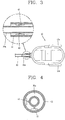
FIG. 3 is a view showing a coupled state between an air pipe and a cleaner body in an autonomous mobile cleaner according to a preferred embodiment of the present invention; -
FIG. 4 is a view showing a coupled state of sensors ofFIG. 3 ; -
FIG. 5 is a block diagram showing an operation to determine a user's intention according to a preferred embodiment of the present invention; -
FIG. 6 is a view showing a sensing unit according to a preferred embodiment of the present invention; and -
FIG. 7 is a flowchart schematically showing a method for moving an autonomous mobile cleaner according to a preferred embodiment of the present invention. - Description will now be given in detail of the exemplary embodiments, with reference to the accompanying drawings. For the sake of brief description with reference to the drawings, the same or equivalent components will be provided with the same reference numbers, and description thereof will not be repeated.
- Referring to
FIGS. 1 to 5 , an autonomous mobile cleaner according to an embodiment of the present invention comprises: acleaner body 10; asuction unit 20 having a handle, and configured to suck foreign materials thereinto; anair pipe 30 configured to connect thecleaner body 10 and thesuction unit 20 to each other, and configured to guide the foreign materials into thecleaner body 10; a sensing unit 40 provided at a connection part between theair pipe 30 and thecleaner body 10, and configured to output a sensing signal by sensing a size and a direction of a tensile strength applied to the air pipe; and acontrol unit 50 configured to move thecleaner body 10 based on the sensing signal. - The autonomous mobile cleaner further comprises a
driving wheel 13 installed at a lower part of thecleaner body 10, and configured to move thecleaner body 10. The autonomous mobile cleaner further comprises adriving unit 60 having a driving motor, and configured to operate the driving wheel by operating the driving motor based on a driving signal. The autonomous mobile cleaner may further comprise an auxiliary wheel not driven by the driving motor, but rotating in a supplementary manner to the driving wheel. - The
control unit 50 includes adisplacement calculator 51 configured to calculate a displacement of the air pipe using the sensing signal of the sensing unit 40, and adriving signal generator 53 configured to generate a driving signal based on the calculated displacement. Here, the driving signal indicates a signal for forward or backward moving thecleaner body 10, or a signal for rotating or stopping thecleaner body 10. - The
control unit 50 controls the distance between a user and thecleaner body 10 to be within a prescribed value, based on the calculated displacement. The prescribed value may be preset. For instance, the prescribed value may be set as a prescribed percentage of the length of the air pipe. Thedriving wheel 13 mounted to thecleaner body 10 is driven by the drivingunit 60. - More specifically, the control unit calculates a displacement for maintaining a constant distance between the user and the cleaner body, based on the sensing signal generated from the sensing unit. Then, the driving motor
drives driving wheels respective driving wheels - The
cleaner body 10 may include adust collecting device 15 mounted thereto in a detachable manner. Thedust collecting device 15 may be called 'dust separating device'. Generally, thedust collecting device 15 is detachably mounted to the front side of thecleaner body 10. Various types of filters may be detachably coupled to thedust collecting device 15. As a suction motor rotates, a suction force is generated. Air sucked into the autonomous mobile cleaner by the generated suction force has dust separated therefrom, while passing through thedust collecting device 15. The separated dust is stored in thedust collecting device 15. - The
suction unit 20 includes ahandle 21 with which a user can operate the autonomous mobile cleaner. Thesuction unit 20 further includes asuction head 23 disposed on the floor so as to suck foreign materials and air. A suction opening through which air and foreign materials such as dust existing on the floor, is formed on the bottom surface of the suction head. An agitator configured to induce foreign materials such as dust into the suction opening, is rotatably formed at the suction opening. Thesuction opening 20 may further include anextension pipe 25 which connects thehandle 21 and thesuction head 23 to each other. - The
air pipe 30 may have a bellows form, and may be formed of synthetic resin, etc. One side of theair pipe 30 is connected to thesuction unit 20, and another side thereof is connected to thecleaner body 10, i.e., theconnection pipe 11. - Referring to
FIG. 3 , thecleaner body 10 may include theconnection pipe 11 at one side thereof, so that theair pipe 30 can be connected to theconnection pipe 11. As shown inFIG. 3 , the sensing unit 40 includes ahall sensor 41 installed at theconnection pipe 11, and amagnet member 43 installed at theair pipe 30a to correspond to thehall sensor 41. For examples, themagnet member 43 is installed at theair pipe 30a to directly face thehall sensor 41. - As shown in
FIG. 3 , theconnection pipe 11 has a cylindrical shape like theair pipe 30, and may be configured in various manners to maintain a constant distance from theair pipe 30. Theconnection pipe 11 may be formed of aluminum, synthetic resin, etc. - Referring to
FIG. 4 , thehall sensor 41 is formed in two, and the two hall sensors are installed in theconnection pipe 11 in directions perpendicular to each other. The number of the hall sensor may be one or at least two, and the arrangement of the hall sensor may be variable according to a displacement measuring method by the control unit. - Referring to
FIGS. 1 to 5 back, an autonomous mobile cleaner according to another embodiment of the present invention comprises acleaner body 10, asuction unit 20, anair pipe 30, a sensing unit 40, acontrol unit 50, and a drivingunit 60. - The
cleaner body 10 is provided with aconnection pipe 11 at one side thereof, and adriving wheel 13 is installed at a lower part of thecleaner body 10. Thesuction unit 20 is provided with ahandle 21, and is configured to suck foreign materials. Theair pipe 30 is connected to theconnection pipe 11, and is configured to guide foreign materials to thecleaner body 10. The sensing unit 40 includes ahall sensor 41 installed in theconnection pipe 11, and amagnet member 43 installed in theair pipe 30 to correspond to thehall sensor 41. The sensing unit 40 is configured to sense a size and a direction of a tensile strength applied to theair pipe 30. Thecontrol unit 50 calculates a displacement of theair pipe 30 based on the sensing signal, and generates a driving signal based on the calculated displacement. The drivingunit 60 operates thedriving wheel 13 based on the driving signal. - Explanations about the same contents as the aforementioned contents in one preferred embodiment will be omitted.
- Referring to
FIG. 4 , thehall sensor 41 is installed in a direction perpendicular to theconnection pipe 11, and a magnet member is attached to theair pipe 30 to correspond to the hall sensor. The sensing unit 40 may be configured to estimate a user's operation intention back and forth and right and left, through the movement of theair pipe 30. - As shown in
FIG. 4 , the autonomous mobile cleaner according to preferred embodiments of the present invention senses the movement of theair pipe 30 using thehall sensors 41 and themagnet members 43, and performs displacement conversion and operation estimation based on the sensed movement. The control unit sets an operation amount of each driving wheel, and the driving unit operates the right and left wheels using the driving motor. The autonomous mobile cleaner may maintain a constant interval between the cleaner body and a user. - As the
hall sensor 41, may be used a linear hall sensor ofFIG. 6 , or a 3D hall sensor, etc. Referring toFIG. 6 , the linear hall sensor is configured to generate a sensing signal (result value) according to a moving distance of a magnet member (permanent magnet) above a sensor. In the case of the linear hall sensor, it operates at a temperature of -30 ∼ 85□, and measures a moving distance (0.5 ∼ 2mm) of the permanent magnet spaced from the linear hall sensor by 1mm, with resolution of 10-bit. Under such principle, the movement amount of the air pipe around the hall sensors can be precisely measured, by permanent magnets installed at theair pipe 30. - Referring to
FIG. 7 , a method for moving an autonomous mobile cleaner according to one embodiment of the present invention comprises: sensing, by a hall sensor, a size and a direction of a tensile strength applied to an air pipe (S10), calculating a displacement of the air pipe based on the size and the direction of the tensile strength (S20), and moving a cleaner body based on the calculated displacement (S30). The autonomous mobile cleaner has the configuration ofFIGS. 1 to 6 . That is, the autonomous mobile cleaner comprises a sensing unit comprised of a hall sensor installed at a connection pipe provided at one side of the cleaner body, and a magnet member installed at an air pipe to correspond to the hall sensor. - The step of moving the cleaner body (S30) includes operating a driving motor provided in the cleaner body based on the calculated displacement (S31), and operating a driving wheel installed at a lower part of the cleaner body by the driving motor (S32). The step of moving the cleaner body (S30) is a step of forward or backward moving the cleaner body, or rotating or stopping the cleaner body.
- The autonomous mobile cleaner senses the movement of the air pipe using the hall sensor and the magnet member (S10), and performs displacement conversion and operation estimation based on the sensed movement (S20). The autonomous mobile cleaner determines an operation amount of each driving wheel (S31), and operates the right and left wheels using the driving motor (S32). The autonomous mobile cleaner maintains a constant interval between the cleaner body and a user, based on the calculated displacement. The prescribed value may be preset. For instance, the prescribed value may be set as a prescribed percentage of the length of the air pipe. More specifically, the autonomous mobile cleaner calculates a displacement for maintaining a constant distance between the user and the cleaner body, based on a sensing signal generated from the hall sensor and the magnet member. Then, the driving motor drives the driving wheels based on the calculated displacement. The respective driving wheels are independently driven, so that the autonomous mobile cleaner can move straight and rotate, and can have a constant distance from the user.
- The autonomous mobile cleaner and the method for moving the same according to the present invention can have the following advantages.
- Firstly, a user's intention is estimated by using a size and a direction of a tensile strength applied to the air pipe. Under such configuration, the autonomous mobile cleaner can autonomously move.
- Secondly, the autonomous mobile cleaner can always and precisely detect a user's operation without having interference with obstacles, using a displacement of the air pipe. Further, the fabrication costs can be reduced and displacements in all directions can be calculated, by using the hall sensors and the magnet members.
- Thirdly, the distance between the cleaner body and a user can be constantly maintained by estimating the user's intention. This can minimize the user's efforts to operate the cleaner, and can prevent damages of the air pipe, a connection part between the cleaner body and the air pipe, etc. due to an excessive force.
- Fourthly, a user can move the mobile cleaner with a less force. This can enhance the user's convenience and stability of the product. Besides, the mobile cleaner can be applied to not only a vacuum cleaner, but also a steam cleaner, a manual forklift, etc., using the hall sensor and the magnet member.
Claims (13)
- An autonomous mobile cleaner, comprising:a cleaner body (10);a suction unit (20) having a handle (21), and configured to suck foreign materials thereinto;an air pipe (30) configured to connect the cleaner body (10) and the suction unit (20) to each other, and configured to guide the foreign materials into the cleaner body (10);a sensing unit (40) provided at a connection part (11) between the air pipe and the cleaner body (10), and configured to output a sensing signal by sensing a size and a direction of a tensile strength applied to the air pipe (30); anda control unit (50) configured to move the cleaner body (10) based on the sensing signal characteirzed in that the control unit (50) is configured to calculate a displacement of the air pipe (30) based on the sensing signal and to control a distance between a user and the cleaner body (10) to be within a prescribed value, based on the calculated displacement.
- The autonomous mobile cleaner of claim 1, further comprising:driving wheels (13) installed at a lower part of the cleaner body (10), and configured to move the cleaner body (10); anda driving unit (60) having a driving motor, and configured to operate the driving wheels (13) by operating the driving motor based on a driving signal.
- The autonomous mobile cleaner of claim 2, wherein the control unit (50) is configured to generate the driving signal based on the calculated displacement.
- The autonomous mobile cleaner of claim 3, wherein the driving signal indicates a signal for forward or backward moving the cleaner body (10), or a signal for rotating or stopping the cleaner body (10).
- The autonomous mobile cleaner of one of claims 1 to 4, wherein the cleaner body (10) includes a connection pipe (11) at one side thereof, so that the air pipe (30) can be connected to the connection pipe (11).
- The autonomous mobile cleaner of claim 5, wherein the sensing unit includes:a hall sensor (41) installed in the connection pipe (11); anda magnet member (43) installed in the air pipe (30a) to correspond to the hall sensor (41).
- The autonomous mobile cleaner of claim 6, wherein the hall sensor (41) is formed in two, and the two hall sensors (41) are installed in the connection pipe (11) in directions perpendicular to each other.
- The autonomous mobile cleaner of claim 1, further comprising:a driving unit (60) configured to operate a driving wheels (13) based on a driving signal,wherein the cleaner body (10) has a connection pipe (11) at one side thereof, and having the driving wheels (13) at a lower part thereof,wherein the air pipe (30) is connected to the connection pipe (11),wherein the sensing unit (40) is comprised of a hall sensor (41) installed in the connection pipe (11), and a magnet member (43) installed in the air pipe (30) to correspond to the hall sensor (41), andwherein the control unit (50) configured to calculate a displacement of the air pipe (30) using the sensing signal, and configured to generate the driving signal based on the calculated displacement.
- The autonomous mobile cleaner of claim 8, wherein the control unit (50) controls the distance between the user and the cleaner body (10) to be within a prescribed value, by forward or backward moving the cleaner body (10), or by rotating or stopping the cleaner body (10).
- The autonomous mobile cleaner of claim 8 or 9, wherein the hall sensor (41) is formed in two, and the two hall sensors (41) are installed in the connection pipe (11) in directions perpendicular to each other.
- A method for moving an autonomous mobile cleaner, in an autonomous mobile cleaner comprising a sensing unit (40) comprised of a hall sensor (41) installed at a connection pipe (11) provided at one side of a cleaner body (10), and a magnet member (43) installed at an air pipe (30) to correspond to the hall sensor (41), the method comprising:sensing (S10), by the hall sensor (41), a size and a direction of a tensile strength applied to the air pipe (30);calculating (S20) a displacement of the air pipe (30) based on the size and the direction of the tensile strength; andmoving the cleaner body (10) based on the calculated displacement,characterized bymoving (S30) the cleaner body (10) to control a distance between a user and the cleaner body (10) to be within a prescribed value, based on the calculated displacement.
- The method of claim 11, wherein the step of moving the cleaner body (10) includes:operating (S31) a driving motor provided in the cleaner body (10) based on the calculated displacement; andoperating (S32) driving wheels (13) installed at a lower part of the cleaner body (10) by the driving motor.
- The method of claim 11 or 12, wherein the step of moving (S30) the cleaner body (10) is a step of forward or backward moving the cleaner body (10), or rotating or stopping the cleaner body (10).
Applications Claiming Priority (1)
| Application Number | Priority Date | Filing Date | Title |
|---|---|---|---|
| KR1020120017553A KR101929813B1 (en) | 2012-02-21 | 2012-02-21 | Autonomous mobile cleaner and moving method of the same |
Publications (3)
| Publication Number | Publication Date |
|---|---|
| EP2630903A2 EP2630903A2 (en) | 2013-08-28 |
| EP2630903A3 EP2630903A3 (en) | 2017-03-29 |
| EP2630903B1 true EP2630903B1 (en) | 2020-11-04 |
Family
ID=47754279
Family Applications (1)
| Application Number | Title | Priority Date | Filing Date |
|---|---|---|---|
| EP13000842.8A Active EP2630903B1 (en) | 2012-02-21 | 2013-02-19 | Autonomous mobile cleaner and method for moving the same |
Country Status (5)
| Country | Link |
|---|---|
| US (1) | US8713748B2 (en) |
| EP (1) | EP2630903B1 (en) |
| KR (1) | KR101929813B1 (en) |
| AU (1) | AU2013200978B2 (en) |
| RU (1) | RU2533676C2 (en) |
Families Citing this family (23)
| Publication number | Priority date | Publication date | Assignee | Title |
|---|---|---|---|---|
| KR102274369B1 (en) | 2013-09-23 | 2021-07-07 | 삼성전자주식회사 | Vacuum cleaner |
| WO2015041499A1 (en) * | 2013-09-23 | 2015-03-26 | 삼성전자주식회사 | Vacuum cleaner |
| KR101555589B1 (en) * | 2014-05-15 | 2015-09-24 | 엘지전자 주식회사 | Method of controlling a cleaner |
| KR102312095B1 (en) | 2014-12-26 | 2021-10-13 | 엘지전자 주식회사 | Autonomous mobile cleaner and method of contorlling the same |
| KR102343100B1 (en) * | 2015-02-13 | 2021-12-24 | 삼성전자주식회사 | Cleaning robot and method for controlling the same |
| GB2564035B8 (en) | 2016-02-29 | 2021-07-07 | Lg Electronics Inc | Vacuum cleaner |
| TWI643596B (en) | 2016-02-29 | 2018-12-11 | Lg電子股份有限公司 | Vacuum cleaner |
| TWI664944B (en) | 2016-02-29 | 2019-07-11 | Lg電子股份有限公司 | Vacuum cleaner |
| DE202017000985U1 (en) | 2016-02-29 | 2017-05-29 | Lg Electronics Inc. | vacuum cleaner |
| WO2017150862A1 (en) | 2016-02-29 | 2017-09-08 | 엘지전자 주식회사 | Vacuum cleaner |
| DE202017000984U1 (en) | 2016-02-29 | 2017-05-29 | Lg Electronics Inc. | vacuum cleaner |
| TWI653962B (en) * | 2016-02-29 | 2019-03-21 | Lg電子股份有限公司 | Vacuum cleaner |
| TWI641353B (en) * | 2016-02-29 | 2018-11-21 | Lg電子股份有限公司 | Vacuum cleaner |
| TWI637718B (en) | 2016-02-29 | 2018-10-11 | Lg電子股份有限公司 | Vacuum cleaner |
| TWI664943B (en) * | 2016-02-29 | 2019-07-11 | Lg電子股份有限公司 | Vacuum cleaner |
| TWI643597B (en) * | 2016-02-29 | 2018-12-11 | Lg電子股份有限公司 | Vacuum cleaner |
| JP6714091B2 (en) * | 2016-02-29 | 2020-06-24 | エルジー エレクトロニクス インコーポレイティド | Vacuum cleaner |
| TWI636758B (en) * | 2016-02-29 | 2018-10-01 | Lg電子股份有限公司 | Vacuum cleaner |
| DE112017000532B4 (en) * | 2016-02-29 | 2023-11-09 | Lg Electronics Inc. | Vacuum cleaner |
| DE202017002619U1 (en) | 2016-05-20 | 2017-08-04 | Lg Electronics Inc. | vacuum cleaner |
| KR101949278B1 (en) * | 2017-02-01 | 2019-02-18 | 엘지전자 주식회사 | Robot cleaner |
| KR102377296B1 (en) * | 2017-06-14 | 2022-03-23 | 엘지전자 주식회사 | Vacuum cleaner |
| KR102521941B1 (en) * | 2018-08-28 | 2023-04-14 | 엘지전자 주식회사 | Cleaner and and method for controlling the same |
Family Cites Families (12)
| Publication number | Priority date | Publication date | Assignee | Title |
|---|---|---|---|---|
| JPH02209017A (en) * | 1989-02-09 | 1990-08-20 | Matsushita Electric Ind Co Ltd | A/d converter |
| JP2683441B2 (en) * | 1990-08-07 | 1997-11-26 | 株式会社テック | Electric vacuum cleaner |
| NL9302171A (en) * | 1993-12-13 | 1995-07-03 | Dutch A & A Trading Bv | Transponder for a detection system. |
| US7043794B2 (en) * | 2003-01-09 | 2006-05-16 | Royal Appliance Mfg. Co. | Self-propelled vacuum cleaner with a neutral return spring |
| US20050071056A1 (en) * | 2003-09-30 | 2005-03-31 | Tondra Aaron P. | Control arrangement for a propulsion unit for a self-propelled floor care appliance |
| KR20060101998A (en) * | 2005-03-22 | 2006-09-27 | 현대모비스 주식회사 | Apparatus for sensing rotor position of ac motor |
| KR100724542B1 (en) * | 2005-08-04 | 2007-06-07 | 전자부품연구원 | Brushless DC Motor |
| KR20090000568A (en) | 2007-02-27 | 2009-01-08 | 주식회사 신한은행 | System and method for transferring fund between online accounts by using enterprise intranet and program recording medium |
| KR100947363B1 (en) * | 2007-11-14 | 2010-03-15 | 엘지전자 주식회사 | Vacuum cleaner |
| EP2152136B1 (en) * | 2007-05-07 | 2013-07-31 | LG Electronics Inc. | Vacuum cleaner |
| KR101052108B1 (en) * | 2008-11-12 | 2011-07-26 | 엘지전자 주식회사 | Vacuum cleaner |
| JP5135182B2 (en) * | 2008-11-26 | 2013-01-30 | 株式会社東芝 | Electric vacuum cleaner |
-
2012
- 2012-02-21 KR KR1020120017553A patent/KR101929813B1/en active IP Right Grant
-
2013
- 2013-02-19 EP EP13000842.8A patent/EP2630903B1/en active Active
- 2013-02-20 RU RU2013107537/12A patent/RU2533676C2/en not_active IP Right Cessation
- 2013-02-20 US US13/771,916 patent/US8713748B2/en active Active
- 2013-02-21 AU AU2013200978A patent/AU2013200978B2/en not_active Ceased
Non-Patent Citations (1)
| Title |
|---|
| None * |
Also Published As
| Publication number | Publication date |
|---|---|
| RU2013107537A (en) | 2014-08-27 |
| RU2533676C2 (en) | 2014-11-20 |
| KR20130096047A (en) | 2013-08-29 |
| EP2630903A2 (en) | 2013-08-28 |
| KR101929813B1 (en) | 2019-03-14 |
| US8713748B2 (en) | 2014-05-06 |
| AU2013200978A1 (en) | 2013-09-05 |
| AU2013200978B2 (en) | 2014-07-24 |
| EP2630903A3 (en) | 2017-03-29 |
| US20130212829A1 (en) | 2013-08-22 |
Similar Documents
| Publication | Publication Date | Title |
|---|---|---|
| EP2630903B1 (en) | Autonomous mobile cleaner and method for moving the same | |
| KR101654014B1 (en) | Mop cleaner robot | |
| EP3236829B1 (en) | Autonomous mobile cleaner and control method thereof | |
| KR102125334B1 (en) | Robot cleaner and controlling method thereof | |
| DK3047783T3 (en) | VACUUM CLEANER ROBOT | |
| EP1360922A2 (en) | Robotic vacuum cleaner with removable portable vacuum head and semi-automated environment mapping | |
| WO2017194101A1 (en) | Adjusting height of a robotic cleaning device | |
| AU2015378048A1 (en) | Vacuum cleaner robot | |
| JP2008155041A (en) | Battery charger for self-propelled vacuum cleaner | |
| CN107105952B (en) | Vacuum cleaner robot | |
| KR101471322B1 (en) | Electric vacuum cleaner | |
| EP2301401A1 (en) | Vacuum cleaner with remote control | |
| KR100901032B1 (en) | Vacuum cleaner | |
| KR101666905B1 (en) | Cleaner and Controlling method for the same | |
| KR20100053095A (en) | Vacuum cleaner | |
| KR20190117173A (en) | Cleaner and controlling method | |
| KR101314678B1 (en) | Cleaner with steering means for head | |
| KR101052108B1 (en) | Vacuum cleaner | |
| KR20200058614A (en) | Detachable wireless robot cleaner | |
| KR100982383B1 (en) | A control method of moving for automatic vacuum cleaner | |
| EP3638089B1 (en) | Vacuum cleaner | |
| KR20110048375A (en) | Robot cleaner | |
| KR100947363B1 (en) | Vacuum cleaner | |
| EP2898808A1 (en) | Canister vacuum cleaner | |
| KR101637360B1 (en) | Cleaner |
Legal Events
| Date | Code | Title | Description |
|---|---|---|---|
| PUAI | Public reference made under article 153(3) epc to a published international application that has entered the european phase |
Free format text: ORIGINAL CODE: 0009012 |
|
| AK | Designated contracting states |
Kind code of ref document: A2 Designated state(s): AL AT BE BG CH CY CZ DE DK EE ES FI FR GB GR HR HU IE IS IT LI LT LU LV MC MK MT NL NO PL PT RO RS SE SI SK SM TR |
|
| AX | Request for extension of the european patent |
Extension state: BA ME |
|
| RIN1 | Information on inventor provided before grant (corrected) |
Inventor name: PARK, JAEHARK Inventor name: YOON, SANGHO |
|
| PUAL | Search report despatched |
Free format text: ORIGINAL CODE: 0009013 |
|
| AK | Designated contracting states |
Kind code of ref document: A3 Designated state(s): AL AT BE BG CH CY CZ DE DK EE ES FI FR GB GR HR HU IE IS IT LI LT LU LV MC MK MT NL NO PL PT RO RS SE SI SK SM TR |
|
| AX | Request for extension of the european patent |
Extension state: BA ME |
|
| RIC1 | Information provided on ipc code assigned before grant |
Ipc: A47L 9/28 20060101ALI20170218BHEP Ipc: A47L 9/24 20060101AFI20170218BHEP |
|
| STAA | Information on the status of an ep patent application or granted ep patent |
Free format text: STATUS: REQUEST FOR EXAMINATION WAS MADE |
|
| 17P | Request for examination filed |
Effective date: 20170711 |
|
| RBV | Designated contracting states (corrected) |
Designated state(s): AL AT BE BG CH CY CZ DE DK EE ES FI FR GB GR HR HU IE IS IT LI LT LU LV MC MK MT NL NO PL PT RO RS SE SI SK SM TR |
|
| GRAP | Despatch of communication of intention to grant a patent |
Free format text: ORIGINAL CODE: EPIDOSNIGR1 |
|
| STAA | Information on the status of an ep patent application or granted ep patent |
Free format text: STATUS: GRANT OF PATENT IS INTENDED |
|
| INTG | Intention to grant announced |
Effective date: 20200528 |
|
| RAP1 | Party data changed (applicant data changed or rights of an application transferred) |
Owner name: LG ELECTRONICS INC. |
|
| GRAS | Grant fee paid |
Free format text: ORIGINAL CODE: EPIDOSNIGR3 |
|
| GRAA | (expected) grant |
Free format text: ORIGINAL CODE: 0009210 |
|
| STAA | Information on the status of an ep patent application or granted ep patent |
Free format text: STATUS: THE PATENT HAS BEEN GRANTED |
|
| AK | Designated contracting states |
Kind code of ref document: B1 Designated state(s): AL AT BE BG CH CY CZ DE DK EE ES FI FR GB GR HR HU IE IS IT LI LT LU LV MC MK MT NL NO PL PT RO RS SE SI SK SM TR |
|
| REG | Reference to a national code |
Ref country code: GB Ref legal event code: FG4D |
|
| REG | Reference to a national code |
Ref country code: CH Ref legal event code: EP |
|
| REG | Reference to a national code |
Ref country code: AT Ref legal event code: REF Ref document number: 1329729 Country of ref document: AT Kind code of ref document: T Effective date: 20201115 |
|
| REG | Reference to a national code |
Ref country code: IE Ref legal event code: FG4D |
|
| REG | Reference to a national code |
Ref country code: DE Ref legal event code: R096 Ref document number: 602013073728 Country of ref document: DE |
|
| REG | Reference to a national code |
Ref country code: NL Ref legal event code: MP Effective date: 20201104 |
|
| REG | Reference to a national code |
Ref country code: AT Ref legal event code: MK05 Ref document number: 1329729 Country of ref document: AT Kind code of ref document: T Effective date: 20201104 |
|
| PG25 | Lapsed in a contracting state [announced via postgrant information from national office to epo] |
Ref country code: FI Free format text: LAPSE BECAUSE OF FAILURE TO SUBMIT A TRANSLATION OF THE DESCRIPTION OR TO PAY THE FEE WITHIN THE PRESCRIBED TIME-LIMIT Effective date: 20201104 Ref country code: RS Free format text: LAPSE BECAUSE OF FAILURE TO SUBMIT A TRANSLATION OF THE DESCRIPTION OR TO PAY THE FEE WITHIN THE PRESCRIBED TIME-LIMIT Effective date: 20201104 Ref country code: NO Free format text: LAPSE BECAUSE OF FAILURE TO SUBMIT A TRANSLATION OF THE DESCRIPTION OR TO PAY THE FEE WITHIN THE PRESCRIBED TIME-LIMIT Effective date: 20210204 Ref country code: PT Free format text: LAPSE BECAUSE OF FAILURE TO SUBMIT A TRANSLATION OF THE DESCRIPTION OR TO PAY THE FEE WITHIN THE PRESCRIBED TIME-LIMIT Effective date: 20210304 Ref country code: GR Free format text: LAPSE BECAUSE OF FAILURE TO SUBMIT A TRANSLATION OF THE DESCRIPTION OR TO PAY THE FEE WITHIN THE PRESCRIBED TIME-LIMIT Effective date: 20210205 |
|
| PGFP | Annual fee paid to national office [announced via postgrant information from national office to epo] |
Ref country code: IT Payment date: 20210225 Year of fee payment: 9 |
|
| PG25 | Lapsed in a contracting state [announced via postgrant information from national office to epo] |
Ref country code: SE Free format text: LAPSE BECAUSE OF FAILURE TO SUBMIT A TRANSLATION OF THE DESCRIPTION OR TO PAY THE FEE WITHIN THE PRESCRIBED TIME-LIMIT Effective date: 20201104 Ref country code: LV Free format text: LAPSE BECAUSE OF FAILURE TO SUBMIT A TRANSLATION OF THE DESCRIPTION OR TO PAY THE FEE WITHIN THE PRESCRIBED TIME-LIMIT Effective date: 20201104 Ref country code: IS Free format text: LAPSE BECAUSE OF FAILURE TO SUBMIT A TRANSLATION OF THE DESCRIPTION OR TO PAY THE FEE WITHIN THE PRESCRIBED TIME-LIMIT Effective date: 20210304 Ref country code: PL Free format text: LAPSE BECAUSE OF FAILURE TO SUBMIT A TRANSLATION OF THE DESCRIPTION OR TO PAY THE FEE WITHIN THE PRESCRIBED TIME-LIMIT Effective date: 20201104 Ref country code: ES Free format text: LAPSE BECAUSE OF FAILURE TO SUBMIT A TRANSLATION OF THE DESCRIPTION OR TO PAY THE FEE WITHIN THE PRESCRIBED TIME-LIMIT Effective date: 20201104 Ref country code: BG Free format text: LAPSE BECAUSE OF FAILURE TO SUBMIT A TRANSLATION OF THE DESCRIPTION OR TO PAY THE FEE WITHIN THE PRESCRIBED TIME-LIMIT Effective date: 20210204 Ref country code: AT Free format text: LAPSE BECAUSE OF FAILURE TO SUBMIT A TRANSLATION OF THE DESCRIPTION OR TO PAY THE FEE WITHIN THE PRESCRIBED TIME-LIMIT Effective date: 20201104 |
|
| REG | Reference to a national code |
Ref country code: LT Ref legal event code: MG9D |
|
| PG25 | Lapsed in a contracting state [announced via postgrant information from national office to epo] |
Ref country code: HR Free format text: LAPSE BECAUSE OF FAILURE TO SUBMIT A TRANSLATION OF THE DESCRIPTION OR TO PAY THE FEE WITHIN THE PRESCRIBED TIME-LIMIT Effective date: 20201104 |
|
| PG25 | Lapsed in a contracting state [announced via postgrant information from national office to epo] |
Ref country code: RO Free format text: LAPSE BECAUSE OF FAILURE TO SUBMIT A TRANSLATION OF THE DESCRIPTION OR TO PAY THE FEE WITHIN THE PRESCRIBED TIME-LIMIT Effective date: 20201104 Ref country code: SK Free format text: LAPSE BECAUSE OF FAILURE TO SUBMIT A TRANSLATION OF THE DESCRIPTION OR TO PAY THE FEE WITHIN THE PRESCRIBED TIME-LIMIT Effective date: 20201104 Ref country code: LT Free format text: LAPSE BECAUSE OF FAILURE TO SUBMIT A TRANSLATION OF THE DESCRIPTION OR TO PAY THE FEE WITHIN THE PRESCRIBED TIME-LIMIT Effective date: 20201104 Ref country code: SM Free format text: LAPSE BECAUSE OF FAILURE TO SUBMIT A TRANSLATION OF THE DESCRIPTION OR TO PAY THE FEE WITHIN THE PRESCRIBED TIME-LIMIT Effective date: 20201104 Ref country code: EE Free format text: LAPSE BECAUSE OF FAILURE TO SUBMIT A TRANSLATION OF THE DESCRIPTION OR TO PAY THE FEE WITHIN THE PRESCRIBED TIME-LIMIT Effective date: 20201104 Ref country code: CZ Free format text: LAPSE BECAUSE OF FAILURE TO SUBMIT A TRANSLATION OF THE DESCRIPTION OR TO PAY THE FEE WITHIN THE PRESCRIBED TIME-LIMIT Effective date: 20201104 |
|
| REG | Reference to a national code |
Ref country code: DE Ref legal event code: R097 Ref document number: 602013073728 Country of ref document: DE |
|
| PG25 | Lapsed in a contracting state [announced via postgrant information from national office to epo] |
Ref country code: DK Free format text: LAPSE BECAUSE OF FAILURE TO SUBMIT A TRANSLATION OF THE DESCRIPTION OR TO PAY THE FEE WITHIN THE PRESCRIBED TIME-LIMIT Effective date: 20201104 |
|
| PLBE | No opposition filed within time limit |
Free format text: ORIGINAL CODE: 0009261 |
|
| STAA | Information on the status of an ep patent application or granted ep patent |
Free format text: STATUS: NO OPPOSITION FILED WITHIN TIME LIMIT |
|
| PG25 | Lapsed in a contracting state [announced via postgrant information from national office to epo] |
Ref country code: MC Free format text: LAPSE BECAUSE OF FAILURE TO SUBMIT A TRANSLATION OF THE DESCRIPTION OR TO PAY THE FEE WITHIN THE PRESCRIBED TIME-LIMIT Effective date: 20201104 |
|
| 26N | No opposition filed |
Effective date: 20210805 |
|
| REG | Reference to a national code |
Ref country code: BE Ref legal event code: MM Effective date: 20210228 |
|
| PG25 | Lapsed in a contracting state [announced via postgrant information from national office to epo] |
Ref country code: AL Free format text: LAPSE BECAUSE OF FAILURE TO SUBMIT A TRANSLATION OF THE DESCRIPTION OR TO PAY THE FEE WITHIN THE PRESCRIBED TIME-LIMIT Effective date: 20201104 Ref country code: CH Free format text: LAPSE BECAUSE OF NON-PAYMENT OF DUE FEES Effective date: 20210228 Ref country code: LU Free format text: LAPSE BECAUSE OF NON-PAYMENT OF DUE FEES Effective date: 20210219 Ref country code: NL Free format text: LAPSE BECAUSE OF FAILURE TO SUBMIT A TRANSLATION OF THE DESCRIPTION OR TO PAY THE FEE WITHIN THE PRESCRIBED TIME-LIMIT Effective date: 20201104 Ref country code: LI Free format text: LAPSE BECAUSE OF NON-PAYMENT OF DUE FEES Effective date: 20210228 |
|
| PG25 | Lapsed in a contracting state [announced via postgrant information from national office to epo] |
Ref country code: SI Free format text: LAPSE BECAUSE OF FAILURE TO SUBMIT A TRANSLATION OF THE DESCRIPTION OR TO PAY THE FEE WITHIN THE PRESCRIBED TIME-LIMIT Effective date: 20201104 |
|
| PG25 | Lapsed in a contracting state [announced via postgrant information from national office to epo] |
Ref country code: FR Free format text: LAPSE BECAUSE OF NON-PAYMENT OF DUE FEES Effective date: 20210228 Ref country code: IE Free format text: LAPSE BECAUSE OF NON-PAYMENT OF DUE FEES Effective date: 20210219 |
|
| PGFP | Annual fee paid to national office [announced via postgrant information from national office to epo] |
Ref country code: GB Payment date: 20220105 Year of fee payment: 10 Ref country code: DE Payment date: 20220105 Year of fee payment: 10 |
|
| PG25 | Lapsed in a contracting state [announced via postgrant information from national office to epo] |
Ref country code: IS Free format text: LAPSE BECAUSE OF FAILURE TO SUBMIT A TRANSLATION OF THE DESCRIPTION OR TO PAY THE FEE WITHIN THE PRESCRIBED TIME-LIMIT Effective date: 20210304 |
|
| PG25 | Lapsed in a contracting state [announced via postgrant information from national office to epo] |
Ref country code: BE Free format text: LAPSE BECAUSE OF NON-PAYMENT OF DUE FEES Effective date: 20210228 |
|
| PG25 | Lapsed in a contracting state [announced via postgrant information from national office to epo] |
Ref country code: IT Free format text: LAPSE BECAUSE OF NON-PAYMENT OF DUE FEES Effective date: 20220219 Ref country code: HU Free format text: LAPSE BECAUSE OF FAILURE TO SUBMIT A TRANSLATION OF THE DESCRIPTION OR TO PAY THE FEE WITHIN THE PRESCRIBED TIME-LIMIT; INVALID AB INITIO Effective date: 20130219 |
|
| PG25 | Lapsed in a contracting state [announced via postgrant information from national office to epo] |
Ref country code: CY Free format text: LAPSE BECAUSE OF FAILURE TO SUBMIT A TRANSLATION OF THE DESCRIPTION OR TO PAY THE FEE WITHIN THE PRESCRIBED TIME-LIMIT Effective date: 20201104 |
|
| REG | Reference to a national code |
Ref country code: DE Ref legal event code: R119 Ref document number: 602013073728 Country of ref document: DE |
|
| GBPC | Gb: european patent ceased through non-payment of renewal fee |
Effective date: 20230219 |
|
| PG25 | Lapsed in a contracting state [announced via postgrant information from national office to epo] |
Ref country code: GB Free format text: LAPSE BECAUSE OF NON-PAYMENT OF DUE FEES Effective date: 20230219 |
|
| PG25 | Lapsed in a contracting state [announced via postgrant information from national office to epo] |
Ref country code: GB Free format text: LAPSE BECAUSE OF NON-PAYMENT OF DUE FEES Effective date: 20230219 Ref country code: DE Free format text: LAPSE BECAUSE OF NON-PAYMENT OF DUE FEES Effective date: 20230901 |