EP2630528B1 - Fiber with asymmetrical core and method for manufacturing same - Google Patents
Fiber with asymmetrical core and method for manufacturing same Download PDFInfo
- Publication number
- EP2630528B1 EP2630528B1 EP10858764.3A EP10858764A EP2630528B1 EP 2630528 B1 EP2630528 B1 EP 2630528B1 EP 10858764 A EP10858764 A EP 10858764A EP 2630528 B1 EP2630528 B1 EP 2630528B1
- Authority
- EP
- European Patent Office
- Prior art keywords
- core
- fiber
- bend
- stretches
- stretch
- Prior art date
- Legal status (The legal status is an assumption and is not a legal conclusion. Google has not performed a legal analysis and makes no representation as to the accuracy of the status listed.)
- Active
Links
Images


Classifications
-
- G—PHYSICS
- G02—OPTICS
- G02B—OPTICAL ELEMENTS, SYSTEMS OR APPARATUS
- G02B6/00—Light guides; Structural details of arrangements comprising light guides and other optical elements, e.g. couplings
- G02B6/02—Optical fibres with cladding with or without a coating
- G02B6/024—Optical fibres with cladding with or without a coating with polarisation maintaining properties
-
- G—PHYSICS
- G02—OPTICS
- G02B—OPTICAL ELEMENTS, SYSTEMS OR APPARATUS
- G02B6/00—Light guides; Structural details of arrangements comprising light guides and other optical elements, e.g. couplings
- G02B6/02—Optical fibres with cladding with or without a coating
-
- C—CHEMISTRY; METALLURGY
- C03—GLASS; MINERAL OR SLAG WOOL
- C03B—MANUFACTURE, SHAPING, OR SUPPLEMENTARY PROCESSES
- C03B37/00—Manufacture or treatment of flakes, fibres, or filaments from softened glass, minerals, or slags
- C03B37/01—Manufacture of glass fibres or filaments
- C03B37/012—Manufacture of preforms for drawing fibres or filaments
- C03B37/01205—Manufacture of preforms for drawing fibres or filaments starting from tubes, rods, fibres or filaments
- C03B37/01225—Means for changing or stabilising the shape, e.g. diameter, of tubes or rods in general, e.g. collapsing
- C03B37/01228—Removal of preform material
-
- G—PHYSICS
- G02—OPTICS
- G02B—OPTICAL ELEMENTS, SYSTEMS OR APPARATUS
- G02B6/00—Light guides; Structural details of arrangements comprising light guides and other optical elements, e.g. couplings
- G02B6/02—Optical fibres with cladding with or without a coating
- G02B6/02004—Optical fibres with cladding with or without a coating characterised by the core effective area or mode field radius
- G02B6/02009—Large effective area or mode field radius, e.g. to reduce nonlinear effects in single mode fibres
-
- G—PHYSICS
- G02—OPTICS
- G02B—OPTICAL ELEMENTS, SYSTEMS OR APPARATUS
- G02B6/00—Light guides; Structural details of arrangements comprising light guides and other optical elements, e.g. couplings
- G02B6/02—Optical fibres with cladding with or without a coating
- G02B6/02295—Microstructured optical fibre
- G02B6/02314—Plurality of longitudinal structures extending along optical fibre axis, e.g. holes
- G02B6/02319—Plurality of longitudinal structures extending along optical fibre axis, e.g. holes characterised by core or core-cladding interface features
- G02B6/02338—Structured core, e.g. core contains more than one material, non-constant refractive index distribution in core, asymmetric or non-circular elements in core unit, multiple cores, insertions between core and clad
-
- G—PHYSICS
- G02—OPTICS
- G02B—OPTICAL ELEMENTS, SYSTEMS OR APPARATUS
- G02B6/00—Light guides; Structural details of arrangements comprising light guides and other optical elements, e.g. couplings
- G02B6/02—Optical fibres with cladding with or without a coating
- G02B6/028—Optical fibres with cladding with or without a coating with core or cladding having graded refractive index
- G02B6/0288—Multimode fibre, e.g. graded index core for compensating modal dispersion
-
- C—CHEMISTRY; METALLURGY
- C03—GLASS; MINERAL OR SLAG WOOL
- C03B—MANUFACTURE, SHAPING, OR SUPPLEMENTARY PROCESSES
- C03B2201/00—Type of glass produced
- C03B2201/06—Doped silica-based glasses
- C03B2201/30—Doped silica-based glasses doped with metals, e.g. Ga, Sn, Sb, Pb or Bi
- C03B2201/34—Doped silica-based glasses doped with metals, e.g. Ga, Sn, Sb, Pb or Bi doped with rare earth metals, i.e. with Sc, Y or lanthanides, e.g. for laser-amplifiers
-
- C—CHEMISTRY; METALLURGY
- C03—GLASS; MINERAL OR SLAG WOOL
- C03B—MANUFACTURE, SHAPING, OR SUPPLEMENTARY PROCESSES
- C03B2203/00—Fibre product details, e.g. structure, shape
- C03B2203/10—Internal structure or shape details
-
- C—CHEMISTRY; METALLURGY
- C03—GLASS; MINERAL OR SLAG WOOL
- C03B—MANUFACTURE, SHAPING, OR SUPPLEMENTARY PROCESSES
- C03B2203/00—Fibre product details, e.g. structure, shape
- C03B2203/10—Internal structure or shape details
- C03B2203/18—Axial perturbations, e.g. in refractive index or composition
-
- C—CHEMISTRY; METALLURGY
- C03—GLASS; MINERAL OR SLAG WOOL
- C03B—MANUFACTURE, SHAPING, OR SUPPLEMENTARY PROCESSES
- C03B2203/00—Fibre product details, e.g. structure, shape
- C03B2203/30—Polarisation maintaining [PM], i.e. birefringent products, e.g. with elliptical core, by use of stress rods, "PANDA" type fibres
-
- H—ELECTRICITY
- H01—ELECTRIC ELEMENTS
- H01S—DEVICES USING THE PROCESS OF LIGHT AMPLIFICATION BY STIMULATED EMISSION OF RADIATION [LASER] TO AMPLIFY OR GENERATE LIGHT; DEVICES USING STIMULATED EMISSION OF ELECTROMAGNETIC RADIATION IN WAVE RANGES OTHER THAN OPTICAL
- H01S3/00—Lasers, i.e. devices using stimulated emission of electromagnetic radiation in the infrared, visible or ultraviolet wave range
- H01S3/05—Construction or shape of optical resonators; Accommodation of active medium therein; Shape of active medium
- H01S3/06—Construction or shape of active medium
- H01S3/063—Waveguide lasers, i.e. whereby the dimensions of the waveguide are of the order of the light wavelength
- H01S3/067—Fibre lasers
- H01S3/06708—Constructional details of the fibre, e.g. compositions, cross-section, shape or tapering
- H01S3/06712—Polarising fibre; Polariser
-
- H—ELECTRICITY
- H01—ELECTRIC ELEMENTS
- H01S—DEVICES USING THE PROCESS OF LIGHT AMPLIFICATION BY STIMULATED EMISSION OF RADIATION [LASER] TO AMPLIFY OR GENERATE LIGHT; DEVICES USING STIMULATED EMISSION OF ELECTROMAGNETIC RADIATION IN WAVE RANGES OTHER THAN OPTICAL
- H01S3/00—Lasers, i.e. devices using stimulated emission of electromagnetic radiation in the infrared, visible or ultraviolet wave range
- H01S3/05—Construction or shape of optical resonators; Accommodation of active medium therein; Shape of active medium
- H01S3/06—Construction or shape of active medium
- H01S3/063—Waveguide lasers, i.e. whereby the dimensions of the waveguide are of the order of the light wavelength
- H01S3/067—Fibre lasers
- H01S3/06708—Constructional details of the fibre, e.g. compositions, cross-section, shape or tapering
- H01S3/06729—Peculiar transverse fibre profile
Definitions
- the disclosure relates to an optical fiber configured with a noncircular core which is structured to minimize the reduction of the effective area of the fundamental mode along curved stretches of the fiber.
- a relatively insignificant displacement of high order modes (HOMs) towards the core periphery along the bend may cause the amplification of the HOM to be substantially greater than the amplification of these modes along the straight stretch of the core.
- HOMs high order modes
- FIGS. 1A and 1B confirm the above.
- FIG. 1A illustrates the fundamental mode displacement in a 32 um core extending along a 9 cm radius;
- FIG. 1B shows the displacement of the mode in a 110 um core along a 15 cm radius.
- the greater the core diameter the greater the mode distortion.
- the methods of fiber manufacturing and fiber configurations minimizing the bend-induced mode distortion are known.
- One of the known structures is configured with a parabolic refractive index profile providing for less reduction of the mode area along a fiber bend than that one of the step-index.
- Also known fiber configurations operating not with a fundamental mode, but with one of higher order modes which each have ⁇ neff- the difference between refractive indices of respective core and mode - higher than that one for the fundamental mode. The higher modes thus are not as susceptible to fiber bends as the fundamental mode is.
- US 2009/041061 A1 discloses a fiber including a thin, doped core. The width can exceed the core thickness by a factor greater than 50, buried inside a flexible glass foil.
- the rectangular fiber core allows for an increase in the core cross-sectional area and therefore output power.
- the short ends can be considered as a characteristic feature which indicates the orientation of the short axis of core.
- the optical fiber can be coiled around a cylinder resulting the short end extending in the plane of the bend.
- JP S58 69804 U discloses an optical fiber having an elliptical core surrounded by a cladding and a plastic coating. The optical fiber has a marking which indicate the orientation of the short axis of the elliptical core.
- US 6 904 219 B1 is a cross section of a flexible planar wave guide wherein the planar core comprises two orthogonal axes of different lengths.
- the planar wave guide comprises a cladding, a depressed index cladding region, a core region and a low refractive index outer coating. To avoid bend losses along the long axis of the planar wave guide, the planar wave guide is preferentially coiled along the short second axis.
- the disclosure teaches an optical fiber as defined in claim 1 and a method of manufacturing an active fiber as defined in claim 6.
- the disclosed fiber is based on the relationship between a parameter S, indicating the degree of the mode distortion, and a radius of core.
- the relationship can be approximated as follows (see: J. M. Fini "Design of LMA amplifier fibers resistant to bend-induced distortion", Vol. 24, No.8/Augusy/2007, Journal of Optical Society of America ).
- ⁇ nbend ncore * Rcore/Rbend, where ⁇ nbend is the difference between refractive indices of respective opposite peripheral segments of the core as a result of the bend, Rcore is the core radius and Rbend is the bend radius of fiber;
- ⁇ neff ncore - neff, where ⁇ neff is the difference between refractive indices of respective mode and core;
- the fundamental mode is displaced which is associated with the appearance of the outer core region (i.e., the region opposite to the direction of the shift or the one relative to the center of the bend).
- an active fiber is provided with the core which has a noncircular configuration characterized by differently dimensioned axes.
- the fiber is positioned so that its smallest axis lies in the plane of the bend.
- the outer cladding of the disclosed fiber is appropriately marked so that the orientation of the short axis is clear for proper spooling and further installation.
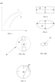
- FIGs. 2A and 2B illustrate one of many possible configurations disclosed LMA fiber 10.
- the fiber 10 includes one or more claddings 18 (only one is shown), and a MM core 12 surrounded by the claddings and doped with one or a combination of rare-earth elements.
- the multimode core 12 is configured to support a single, preferably fundamental transverse or very few modes at the desired wavelength. As shown from the illustrated example of the disclosed fiber, core 12 has an elliptical shaped cross-section.
- the fiber 10 may or may not be polarization maintaining fiber; the fiber is an active fiber.
- the multimode elliptical core 12 is configured with a short axis 14 and a long axis 16 ( FIG. 2B ).
- active fiber 10 with asymmetrically-shaped core 12 is positioned along a bend so that short axis 14 extends along the plane and in the plane of the bend.
- FIG. 3 illustrates one of techniques providing the user with a simple and effective structure for proper positioning of fiber 10 along a bend.
- outer cladding 18 is provided with a marking 20, also seen in FIG. 2A , indicating the orientation of the short axis 14. This can be easily realized by applying paint to the cladding along the desired direction from a paint reservoir 25.
- FIG. 4 illustrates a slightly modified core 22 provided with opposite curved stretches each with a radius R, and two rectilinear stretches each having a length L and bridging the curved stretches.
- the fundamental mode in core 22, like in core 12 of FIG.3 is elongated along the long axis.
- FIGS. 5 and 6 illustrate the mode shape change in core 22 of FIG. 4 .
- core 22 is asymmetrical, the mode behavior depends on the plane in which the bend extends.
- the center of the bend lies on short axis 14, i.e., the fiber is curved along a short axis which lies in the plane of the bend.
- the mode 24 substantially preserves its shape and is only slightly displaced relative to the center of core 22.
- the bend extends in the plane of long axis 16 as shown in FIG. 6 , the distortion of the mode is clearly manifested by the reduced mode area and the shift of the mode towards the circumference from the center of core 22.
- FIG. 7 illustrates the dependence of the mode area from the bend radius for two different bend planes: 0 degrees and 90 degrees.
- the 0-degree graph clearly shows greater mode distortion.
- the core shape and therefore mode intensity profile is not limited to the elliptical shape and can be manufactured with any regular shape or irregular shape.
- the regular shape may be, for example, a polygonal shape which without limitation includes triangular, rectangular, star-like and etc.
- FIG. 8 illustrates an example of polygonal shape represented by a rectangular.
- FIG. 9 illustrates an example of irregular shape including two rectilinear sides bridged by inwardly curved sides.
- the criticality of the core's geometry in accordance with the disclosure is the presence of multiple axes with one of the them being the smallest.
- the core shape is a function of the number of cuts through a preform, the depth and direction at which the cuts extend and process temperature.
- FIGs. 10A and 10B schematically illustrate the method of manufacturing fiber 10 having elliptical core 12.
- a preform 30 ( FIG. 10A ) is provided with diametrically opposite cuts 32.
- a round core 34 accepts an elliptical shape of core shown in FIG. 10B .
- FIG. 11 illustrates a technique for configuring a rectangular core.
- two pairs of cuts each including a pair of diametrically opposite and differently- dimensioned indents 40, is made in a preform 42.
- the cuts may or may not be uniform and may be positioned diametrically asymmetrically, have different depth and direction all depending on the desired core shape.
- FIG. 12 illustrates a fiber laser system 50 not being part of the present invention provided with a large mode area fiber 52 which is configured with a multimode (MM) core doped with one or more rare earth elements and having, for example, an elliptically-shaped cross-section.
- the laser system 50 further may include input and output passive fibers 56 and 58, respectively which support propagation of a fundamental mode.
- the passive fibers each may have a single mode or multimode structure; if the passive fiber is configured as a multimode fiber, substantially only a fundamental mode is excited at the input of such a fiber.
- Completing system 50 is a passive MM delivery fiber 60 launching pump light into active fiber 52 in accordance with a side pump scheme.
- FIG. 13 diagrammatically illustrates a bottom 64 of a fiber block's housing 62 not being part of the present invention. While fiber block 62 may a variety of shapes, the illustrated one has an elliptical shape.
- the bottom 64 is provided with a guide 66 configured to receive and guide active fiber 52 of FIG. 12 along a path having two bends 68.
- the active fiber thus has two curved stretches corresponding to the opposite bends 68 of guide 66.
- the active fiber is provided with an asymmetrically shaped core and extends along the bends so that the shortest axis of the core extends along the curved segment of each bends 68.
- passive input and output fibers 56, 58 each are configured with substantially uniform elliptical preferably, but not necessarily, SM core 54. Accordingly, when passive and active fibers are butt-spliced, the respective cores are aligned which allows for the excitement of substantially only a fundamental mode in active fiber 52.
- FIG. 15 discussed in conjunction with FIG. 12 , illustrates the other configuration providing for minimal light losses.
- the active fiber 52 according to the invention is drawn with alternating regions 62, 64, respectively, having different core profiles.
- the region 62 has a typical circular core
- region 64 is configured with an asymmetrically-shaped core and insignia on the outer periphery which indicates the correct orientation of the core's short axis.
- the circular cores of respective input and output regions 62 each are shaped and dimensioned so that a MFD of SM signal light supported by input passive fiber 56 ( FIG. 12 ) substantially matches that one of the fundamental mode of active fiber 52.
- a SM passive output fiber 58 is configured so that the circularly-profiled fundamental mode propagating through a butt-splice region between these fibers does not loose any substantial power.
- the active fiber 52 is further so configured that it has a transitional region between regions 62 and 64 along which the circular profile transform into the elliptical one and back to the circular one.
Landscapes
- Physics & Mathematics (AREA)
- Optics & Photonics (AREA)
- General Physics & Mathematics (AREA)
- Chemical & Material Sciences (AREA)
- Engineering & Computer Science (AREA)
- Geochemistry & Mineralogy (AREA)
- Materials Engineering (AREA)
- Organic Chemistry (AREA)
- Manufacturing & Machinery (AREA)
- Life Sciences & Earth Sciences (AREA)
- General Life Sciences & Earth Sciences (AREA)
- Dispersion Chemistry (AREA)
- Lasers (AREA)
- Manufacture, Treatment Of Glass Fibers (AREA)
Description
- The disclosure relates to an optical fiber configured with a noncircular core which is structured to minimize the reduction of the effective area of the fundamental mode along curved stretches of the fiber.
- The advent of high power fiber laser systems would not be possible without large mode area (LMA) active fibers. As the power scaling of fiber laser systems grows, strict requirements are applied to the quality of lased radiation. As known to an ordinary skilled worker in the art ("posita"), the fewer the modes guided along the core, the higher the light quality. Hence great efforts are made to configure MM fibers capable of supporting substantially a single, nearly diffraction-limited fundamental mode at the desired wavelength. Once the latter is properly exited, the MM core guides this mode further down a light path without substantial distortion. The latter is largely correct in the context of substantially straight fibers. In practice, however, fibers typically have bends or curved stretches.
- Typically for standard fibers, such as fibers with a step-index profile of the core, when a fundamental mode propagates along a curved stretch, its effective area, i.e., a quantitative measure of the area which a mode effectively covers in the transverse dimension, decreases. The displacement of the fundamental mode towards the periphery of the core causes an overlapped area, i.e., the area common to a core region with gain medium and fundamental mode, to shrink. At the same time, the displacement of high order modes towards the core periphery along the bend is not as great as in the case of the fundamental mode. A relatively insignificant displacement of high order modes (HOMs) towards the core periphery along the bend may cause the amplification of the HOM to be substantially greater than the amplification of these modes along the straight stretch of the core. The greater the amplification of HOMs, the lower the quality of the output beam.
- As the core area increases, the above disclosed effects become more and more pronounced. These phenomena appear to be one of the main factors limiting the enlargement of the core area and, therefore, the power scaling of active fibers with a step index profile and core diameters at least equal to about 30 µm.
-
FIGS. 1A and 1B confirm the above.FIG. 1A illustrates the fundamental mode displacement in a 32 um core extending along a 9 cm radius;FIG. 1B shows the displacement of the mode in a 110 um core along a 15 cm radius. Clearly, the greater the core diameter, the greater the mode distortion. - The methods of fiber manufacturing and fiber configurations minimizing the bend-induced mode distortion are known. One of the known structures is configured with a parabolic refractive index profile providing for less reduction of the mode area along a fiber bend than that one of the step-index. Also known fiber configurations operating not with a fundamental mode, but with one of higher order modes which each have Δneff- the difference between refractive indices of respective core and mode - higher than that one for the fundamental mode. The higher modes thus are not as susceptible to fiber bends as the fundamental mode is.
US 2009/041061 A1 discloses a fiber including a thin, doped core. The width can exceed the core thickness by a factor greater than 50, buried inside a flexible glass foil. The rectangular fiber core allows for an increase in the core cross-sectional area and therefore output power. The short ends can be considered as a characteristic feature which indicates the orientation of the short axis of core. The optical fiber can be coiled around a cylinder resulting the short end extending in the plane of the bend.
JP S58 69804 U
US 6 904 219 B1 is a cross section of a flexible planar wave guide wherein the planar core comprises two orthogonal axes of different lengths. The planar wave guide comprises a cladding, a depressed index cladding region, a core region and a low refractive index outer coating. To avoid bend losses along the long axis of the planar wave guide, the planar wave guide is preferentially coiled along the short second axis. - The disclosure teaches an optical fiber as defined in claim 1 and a method of manufacturing an active fiber as defined in claim 6.
- The disclosed fiber is based on the relationship between a parameter S, indicating the degree of the mode distortion, and a radius of core. The relationship can be approximated as follows (see: J. M. Fini "Design of LMA amplifier fibers resistant to bend-induced distortion", Vol. 24, No.8/Augusy/2007, Journal of Optical Society of America).
- Δnbend = ncore * Rcore/Rbend, where Δnbend is the difference between refractive indices of respective opposite peripheral segments of the core as a result of the bend, Rcore is the core radius and Rbend is the bend radius of fiber;
- Δneff = ncore - neff, where Δneff is the difference between refractive indices of respective mode and core;
- Based on the foregoing, when Δneff < Δnbend, the fundamental mode is displaced which is associated with the appearance of the outer core region (i.e., the region opposite to the direction of the shift or the one relative to the center of the bend).
- The parameter of distortion S = Δnbend/ Δneff
- Since Δneff - C*(l/Rcore)2, S is proportional to R3 core. Thus, the smaller the radius, the smaller the distortion.
- According to the disclosure, an active fiber is provided with the core which has a noncircular configuration characterized by differently dimensioned axes. To minimize the mode distortion along a bend, the fiber is positioned so that its smallest axis lies in the plane of the bend. The outer cladding of the disclosed fiber is appropriately marked so that the orientation of the short axis is clear for proper spooling and further installation.
- The disclosure is further described in detail illustrated by the following drawings.
-
FIGS. 1A and 1B illustrate the behavior of the mode in a circularly-shaped core of fiber not being part of the present invention extending along bends with respective smaller and larger radii. -
FIGs. 2A and 2B illustrate elevation side and cross-sectional views, respectively, of an exemplary elliptically shaped asymmetrical core configured in accordance with the disclosure. -
FIG. 3 illustrates a technique of marking the cladding of the disclosed fiber with insignia indicating the direction of the short axis of the asymmetrical core ofFIG. 2B . -
FIGS. 4 illustrate a modification of the asymmetrical core of the disclosed fiber. -
FIG. 5 illustrates distortion of the mode supported by the core ofFIG. 6 when the short axis of the core lies in the plane of a bend. -
FIG. 6 illustrates distortion of the mode supported by the core ofFIG. 6 when the short axis of the asymmetrical core lies in the plane perpendicular to that one of the bend. -
FIG. 7 is a graph illustrating the dependence of the degree of the mode area distortion from the bend radius for two bend planes of respectiveFIGs. 5 and 6 . -
FIGs. 8 and 9 illustrate further exemplary respective shapes of the asymmetrical core of the disclosed fiber. -
FIG. 10A and 10B illustrate an exemplary technique used in the disclosed process of manufacturing of the disclosed asymmetrical core. -
FIG. 11 illustrates one of the stages of the disclosed process. -
FIG. 12 is a fiber laser system not being part of the present invention incorporating the disclosed fiber. -
FIG. 13 is a view of the bottom half of the housing enclosing the system not being part of the present invention shown inFIG. 12 . -
FIG. 14 illustrates configurations of respective passive and active fibers of the system ofFIG. 12 . -
FIG. 15 illustrates a further modification of the disclosed fiber. - Reference will now be made in detail to the disclosed system. Wherever possible, same or similar reference numerals are used in the drawings and the description to refer to the same or like parts or steps. The directional terms including, but not limited to such words as up, down and the like are to be interpreted exclusively with respect to the plane of the sheet. The drawings are in simplified form and far from precise scale.
-
FIGs. 2A and 2B illustrate one of many possible configurations disclosedLMA fiber 10. Thefiber 10 includes one or more claddings 18 (only one is shown), and aMM core 12 surrounded by the claddings and doped with one or a combination of rare-earth elements. Themultimode core 12 is configured to support a single, preferably fundamental transverse or very few modes at the desired wavelength. As shown from the illustrated example of the disclosed fiber,core 12 has an elliptical shaped cross-section. Thefiber 10 may or may not be polarization maintaining fiber; the fiber is an active fiber. - The multimode
elliptical core 12 is configured with ashort axis 14 and a long axis 16 (FIG. 2B ). In accordance with the disclosure,active fiber 10 with asymmetrically-shapedcore 12 is positioned along a bend so thatshort axis 14 extends along the plane and in the plane of the bend. -
FIG. 3 illustrates one of techniques providing the user with a simple and effective structure for proper positioning offiber 10 along a bend. In particular, during the drawing step of the disclosed manufacturing process,outer cladding 18 is provided with a marking 20, also seen inFIG. 2A , indicating the orientation of theshort axis 14. This can be easily realized by applying paint to the cladding along the desired direction from apaint reservoir 25. -
FIG. 4 illustrates a slightly modifiedcore 22 provided with opposite curved stretches each with a radius R, and two rectilinear stretches each having a length L and bridging the curved stretches. The fundamental mode incore 22, like incore 12 ofFIG.3 , is elongated along the long axis. -
FIGS. 5 and 6 illustrate the mode shape change incore 22 ofFIG. 4 . Sincecore 22 is asymmetrical, the mode behavior depends on the plane in which the bend extends. InFIG. 5 , the center of the bend lies onshort axis 14, i.e., the fiber is curved along a short axis which lies in the plane of the bend. Themode 24 substantially preserves its shape and is only slightly displaced relative to the center ofcore 22. In contrast, when the bend extends in the plane oflong axis 16, as shown inFIG. 6 , the distortion of the mode is clearly manifested by the reduced mode area and the shift of the mode towards the circumference from the center ofcore 22. -
FIG. 7 illustrates the dependence of the mode area from the bend radius for two different bend planes: 0 degrees and 90 degrees. The 0-degree graph clearly shows greater mode distortion. - Referring to
FIGs. 8 and 9 , the core shape and therefore mode intensity profile is not limited to the elliptical shape and can be manufactured with any regular shape or irregular shape. The regular shape may be, for example, a polygonal shape which without limitation includes triangular, rectangular, star-like and etc.FIG. 8 illustrates an example of polygonal shape represented by a rectangular.FIG. 9 illustrates an example of irregular shape including two rectilinear sides bridged by inwardly curved sides. The criticality of the core's geometry in accordance with the disclosure is the presence of multiple axes with one of the them being the smallest. In general, the core shape is a function of the number of cuts through a preform, the depth and direction at which the cuts extend and process temperature. -
FIGs. 10A and 10B schematically illustrate the method ofmanufacturing fiber 10 havingelliptical core 12. A preform 30 (FIG. 10A ) is provided with diametrically opposite cuts 32. As the fiber being drawn, around core 34 accepts an elliptical shape of core shown inFIG. 10B . -
FIG. 11 illustrates a technique for configuring a rectangular core. To receive the latter, two pairs of cuts each including a pair of diametrically opposite and differently- dimensionedindents 40, is made in apreform 42. In general, the cuts may or may not be uniform and may be positioned diametrically asymmetrically, have different depth and direction all depending on the desired core shape. -
FIG. 12 illustrates afiber laser system 50 not being part of the present invention provided with a largemode area fiber 52 which is configured with a multimode (MM) core doped with one or more rare earth elements and having, for example, an elliptically-shaped cross-section. Thelaser system 50 further may include input and outputpassive fibers system 50 is a passiveMM delivery fiber 60 launching pump light intoactive fiber 52 in accordance with a side pump scheme. -
FIG. 13 diagrammatically illustrates a bottom 64 of a fiber block'shousing 62 not being part of the present invention. Whilefiber block 62 may a variety of shapes, the illustrated one has an elliptical shape. The bottom 64 is provided with aguide 66 configured to receive and guideactive fiber 52 ofFIG. 12 along a path having two bends 68. The active fiber thus has two curved stretches corresponding to the opposite bends 68 ofguide 66. In accordance with the disclosure of the invention, the active fiber is provided with an asymmetrically shaped core and extends along the bends so that the shortest axis of the core extends along the curved segment of each bends 68. - With the proliferation of high-power fiber lasers, strict requirements are often applied to the quality and power of output light. To prevent unacceptable power loss of signal light launched from
input fiber 56 intoMM core 54 and excitement of high order modes in the latter, it is necessary that a mode field diameter of fundamental mode ofactive fiber 52 substantially match that one ofinput fiber 56. These can be attained by two following configurations, wherein the first configuration referring toFigs. 12 and 14 is not according to the invention and is present for illustration purposes only. - Referring to
FIG. 14 and considering the latter in light ofFIG. 12 , passive input andoutput fibers SM core 54. Accordingly, when passive and active fibers are butt-spliced, the respective cores are aligned which allows for the excitement of substantially only a fundamental mode inactive fiber 52.FIG. 15 , discussed in conjunction withFIG. 12 , illustrates the other configuration providing for minimal light losses. In particular, theactive fiber 52 according to the invention is drawn with alternatingregions region 62 has a typical circular core, whereasregion 64 is configured with an asymmetrically-shaped core and insignia on the outer periphery which indicates the correct orientation of the core's short axis. The circular cores of respective input andoutput regions 62 each are shaped and dimensioned so that a MFD of SM signal light supported by input passive fiber 56 (FIG. 12 ) substantially matches that one of the fundamental mode ofactive fiber 52. Similarly, a SMpassive output fiber 58 is configured so that the circularly-profiled fundamental mode propagating through a butt-splice region between these fibers does not loose any substantial power. Theactive fiber 52 is further so configured that it has a transitional region betweenregions - Although shown and described is what is believed to be the most practical and preferred embodiments, it is apparent that departures from specific designs and methods described and shown will suggest themselves to those skilled in the art and may be used without departing from the scope of the invention. The present invention is not restricted to the particular constructions described and illustrated, but should be construed to cohere with all modifications that may fall within the scope of the appended claims.
Claims (8)
- An optical active (10, 52) fiber comprising:- a plurality of core stretches (62, 64), the core stretches (62, 64) having respective asymmetrical and symmetrically shapes which alternate each other,- wherein each stretch (64) of an asymmetrically-shaped core (12) has at least one long axis (16) and a short axis (14) smaller than the long axis (16) and extending transversely thereto,- wherein each stretch (62) of symmetrically-shaped core has a circular core profile,- and an outmost cladding (18) surrounding the core (12) and having a marking (20) which indicates the orientation of the short axis (14).
- The fiber of claim 1, wherein the short axis (14) extends along and is coplanar with a bend region of at least one stretch (64).
- The fiber of claim 1, wherein the core (12) is not doped with or doped with one or more rare-earth ions and configured to support multiple modes in a range of wavelengths except for one desired wavelength at which the core supports substantially a fundamental or very few modes.
- The optical fiber of claim 1 further comprising at least one additional cladding concentric with the core (12) and outmost cladding (18), the core and claddings being configured to define a large mode area (LMA) fiber configuration.
- The optical fiber of claim 4, wherein the LMA fiber configuration includes a polarization maintaining or not polarization maintaining structure.
- A method of manufacturing an active fiber comprising(a) drawing a plurality of alternating one and additional fiber stretches (62, 64),(b) drawing the one stretches (64) of the fiber (12, 52) with an asymmetrically shaped core (12) doped with one or more rare-earth ions, thereby configuring the core (12) with multiple axes (14, 16) one of which is a shortest axis (14); and(c) simultaneously with (b), marking an outmost cladding (18) of the fiber surrounding the core (12) so as to indicate the orientation of the shortest axis (14) and(d) drawing the additional stretches (62) having a core with a circular shape and(e) color-coding beginning and end of each one stretch (64) or each additional stretch (62).
- The method of claim 6 further comprising providing a plurality of cuts (32) on a preform (30) before drawing the fiber, the cuts (32) being:spaced from one another at a uniform or varying angular distance,extending relative to one another at a uniform angle or varying angle.
- The method of claim 7 further comprising bending the fiber, thereby forming a bend having a plane, wherein the shortest axis (14) extends along and lies in the plane of the bend.
Applications Claiming Priority (1)
| Application Number | Priority Date | Filing Date | Title |
|---|---|---|---|
| PCT/US2010/053646 WO2012054047A1 (en) | 2010-10-22 | 2010-10-22 | Fiber with asymmetrical core and method for manufacturing same |
Publications (3)
| Publication Number | Publication Date |
|---|---|
| EP2630528A1 EP2630528A1 (en) | 2013-08-28 |
| EP2630528A4 EP2630528A4 (en) | 2017-12-13 |
| EP2630528B1 true EP2630528B1 (en) | 2023-04-05 |
Family
ID=45975523
Family Applications (1)
| Application Number | Title | Priority Date | Filing Date |
|---|---|---|---|
| EP10858764.3A Active EP2630528B1 (en) | 2010-10-22 | 2010-10-22 | Fiber with asymmetrical core and method for manufacturing same |
Country Status (6)
| Country | Link |
|---|---|
| EP (1) | EP2630528B1 (en) |
| JP (1) | JP5410617B2 (en) |
| KR (1) | KR101222014B1 (en) |
| CN (1) | CN102782539A (en) |
| DK (1) | DK2630528T3 (en) |
| WO (1) | WO2012054047A1 (en) |
Families Citing this family (4)
| Publication number | Priority date | Publication date | Assignee | Title |
|---|---|---|---|---|
| CN104470671B (en) * | 2012-06-22 | 2016-06-08 | Ipg光子公司 | For producing the method for drilling holes and boring assemblies shaping hole |
| EP2972528B1 (en) * | 2013-03-15 | 2017-11-22 | NLIGHT, Inc. | Spun non-circular and non-elliptical fibers and apparatuses utilizing the same |
| RU2700723C2 (en) * | 2014-08-13 | 2019-09-19 | Айпиджи Фотоникс Корпорэйшн | Fibre laser system with multiple beams |
| US9917410B2 (en) * | 2015-12-04 | 2018-03-13 | Nlight, Inc. | Optical mode filter employing radially asymmetric fiber |
Family Cites Families (14)
| Publication number | Priority date | Publication date | Assignee | Title |
|---|---|---|---|---|
| JPS5869804U (en) | 1981-11-02 | 1983-05-12 | 日本電気株式会社 | Polarization preserving optical fiber core |
| JPS58105503U (en) * | 1982-01-13 | 1983-07-18 | 日立電線株式会社 | Constant polarization optical fiber |
| CA1288701C (en) * | 1986-11-18 | 1991-09-10 | Cheng-Kuei Jen | Birefringent single-mode acoustic fiber |
| IT1236632B (en) * | 1989-10-24 | 1993-03-25 | Pirelli Cavi Spa | AMPLIFIER FOR FIBER OPTIC TELECOMMUNICATIONS LINES AND FIBER OPTIC TELECOMMUNICATIONS LINES INCORPORATING SAID AMPLIFIER |
| CA2440938A1 (en) * | 2001-03-16 | 2002-09-26 | Sumitomo Electric Industries, Ltd. | Optical fiber and method of manufacturing the same |
| US6948340B2 (en) * | 2001-03-22 | 2005-09-27 | Moritex Corporation | Method of producing an elliptic core optical fiber |
| US6904219B1 (en) * | 2002-07-26 | 2005-06-07 | Boston Laser, Inc. | Ultra high-power continuous wave planar waveguide amplifiers and lasers |
| US7194172B2 (en) * | 2003-06-19 | 2007-03-20 | Corning Incorporated | Single polarization optical fiber and system and method for producing same |
| JP2005115103A (en) * | 2003-10-09 | 2005-04-28 | Hitachi Cable Ltd | Elliptical core optical fiber |
| US7983312B2 (en) | 2007-08-09 | 2011-07-19 | Raytheon Company | Method and apparatus for generation and amplification of light in a semi-guiding high aspect ratio core fiber |
| US7593435B2 (en) * | 2007-10-09 | 2009-09-22 | Ipg Photonics Corporation | Powerful fiber laser system |
| US7839901B2 (en) * | 2008-12-03 | 2010-11-23 | Ipg Photonics Corporation | High power fiber laser system with cladding light stripper |
| CN101447637B (en) * | 2008-12-31 | 2010-08-11 | 华南理工大学 | A Low Noise Narrow Linewidth High Power Single Longitudinal Mode Fiber Laser |
| CN101771233B (en) * | 2010-01-18 | 2012-03-07 | 北京交通大学 | High-power, multiband and multilayer annual core laser doped with rare earth ions |
-
2010
- 2010-10-22 EP EP10858764.3A patent/EP2630528B1/en active Active
- 2010-10-22 CN CN2010800458382A patent/CN102782539A/en active Pending
- 2010-10-22 DK DK10858764.3T patent/DK2630528T3/en active
- 2010-10-22 JP JP2012548005A patent/JP5410617B2/en active Active
- 2010-10-22 WO PCT/US2010/053646 patent/WO2012054047A1/en not_active Ceased
- 2010-10-22 KR KR1020127009406A patent/KR101222014B1/en active Active
Also Published As
| Publication number | Publication date |
|---|---|
| WO2012054047A1 (en) | 2012-04-26 |
| DK2630528T3 (en) | 2023-04-17 |
| JP2013516787A (en) | 2013-05-13 |
| EP2630528A1 (en) | 2013-08-28 |
| KR101222014B1 (en) | 2013-01-15 |
| JP5410617B2 (en) | 2014-02-05 |
| EP2630528A4 (en) | 2017-12-13 |
| CN102782539A (en) | 2012-11-14 |
| KR20120054650A (en) | 2012-05-30 |
Similar Documents
| Publication | Publication Date | Title |
|---|---|---|
| JP7535557B2 (en) | Mode-mixing optical fiber and methods and systems using same - Patents.com | |
| US6987783B2 (en) | Three-level air-clad rare-earth doped fiber laser/amplifier | |
| EP1242325B1 (en) | Optical fiber with irregularities at cladding boundary and method of its fabrication | |
| US9042695B2 (en) | Low bending loss multimode fiber transmission system | |
| EP2321678B1 (en) | Optical fiber with resonant structure of cladding features connected to light sink | |
| CN107924023B (en) | Fibers with suppressed central index of refraction for increased beam parameter product | |
| US7760771B2 (en) | Optical fiber gain medium with modal discrimination of amplification | |
| EP3025175B1 (en) | Single large mode cladding amplification in active double-clad fibers | |
| EP2965390B1 (en) | Ultra high power single mode fiber laser system with non-uniformly configured fiber-to fiber rod multimode amplifier | |
| EP2646863A2 (en) | Large-mode-area optical fibers with bend compensation | |
| JP2019504350A (en) | Hollow core optical fiber and laser system | |
| EP1402295B1 (en) | Ring core fiber | |
| WO2008076162A2 (en) | Large mode area fiber for low-loss transmission and amplification of single mode lasers | |
| US12444896B2 (en) | Optical fiber devices and methods for directing stimulated raman scattering (SRS) light out of a fiber core and into a cladding | |
| CN113383251B (en) | Fiber optic device and method for suppressing stimulated Raman scattering (SRS) | |
| JP2005019539A (en) | Rare earth doped fiber and optical fiber laser using the same | |
| US9031099B2 (en) | Fiber with asymmetrical core and method for manufacturing same | |
| EP2639606A2 (en) | Gradient-index multimode optical fibers for optical fiber connectors | |
| US7978943B2 (en) | Monolithic pump coupler for high-aspect ratio solid-state gain media | |
| CN108292010B (en) | Photonic crystal fiber and high-power optical transmission system | |
| WO2012054047A1 (en) | Fiber with asymmetrical core and method for manufacturing same | |
| US7463807B2 (en) | Waveguide configuration | |
| EP3295228B1 (en) | Single mode large mode area optical fiber coil | |
| CN115087896A (en) | Optical fiber and optical fiber laser device |
Legal Events
| Date | Code | Title | Description |
|---|---|---|---|
| PUAI | Public reference made under article 153(3) epc to a published international application that has entered the european phase |
Free format text: ORIGINAL CODE: 0009012 |
|
| 17P | Request for examination filed |
Effective date: 20130603 |
|
| AK | Designated contracting states |
Kind code of ref document: A1 Designated state(s): AL AT BE BG CH CY CZ DE DK EE ES FI FR GB GR HR HU IE IS IT LI LT LU LV MC MK MT NL NO PL PT RO RS SE SI SK SM TR |
|
| DAX | Request for extension of the european patent (deleted) | ||
| RA4 | Supplementary search report drawn up and despatched (corrected) |
Effective date: 20171109 |
|
| RIC1 | Information provided on ipc code assigned before grant |
Ipc: H01S 3/067 20060101ALI20171103BHEP Ipc: C03B 37/012 20060101ALI20171103BHEP Ipc: G02B 6/028 20060101ALI20171103BHEP Ipc: G02B 6/26 20060101ALI20171103BHEP Ipc: G02B 6/02 20060101AFI20171103BHEP |
|
| STAA | Information on the status of an ep patent application or granted ep patent |
Free format text: STATUS: EXAMINATION IS IN PROGRESS |
|
| 17Q | First examination report despatched |
Effective date: 20210423 |
|
| RIC1 | Information provided on ipc code assigned before grant |
Ipc: G02B 6/26 20060101ALI20220519BHEP Ipc: H01S 3/067 20060101ALI20220519BHEP Ipc: G02B 6/028 20060101ALI20220519BHEP Ipc: C03B 37/012 20060101ALI20220519BHEP Ipc: G02B 6/02 20060101AFI20220519BHEP |
|
| GRAP | Despatch of communication of intention to grant a patent |
Free format text: ORIGINAL CODE: EPIDOSNIGR1 |
|
| STAA | Information on the status of an ep patent application or granted ep patent |
Free format text: STATUS: GRANT OF PATENT IS INTENDED |
|
| INTG | Intention to grant announced |
Effective date: 20220725 |
|
| GRAJ | Information related to disapproval of communication of intention to grant by the applicant or resumption of examination proceedings by the epo deleted |
Free format text: ORIGINAL CODE: EPIDOSDIGR1 |
|
| STAA | Information on the status of an ep patent application or granted ep patent |
Free format text: STATUS: EXAMINATION IS IN PROGRESS |
|
| INTC | Intention to grant announced (deleted) | ||
| GRAP | Despatch of communication of intention to grant a patent |
Free format text: ORIGINAL CODE: EPIDOSNIGR1 |
|
| STAA | Information on the status of an ep patent application or granted ep patent |
Free format text: STATUS: GRANT OF PATENT IS INTENDED |
|
| INTG | Intention to grant announced |
Effective date: 20221207 |
|
| GRAS | Grant fee paid |
Free format text: ORIGINAL CODE: EPIDOSNIGR3 |
|
| GRAA | (expected) grant |
Free format text: ORIGINAL CODE: 0009210 |
|
| STAA | Information on the status of an ep patent application or granted ep patent |
Free format text: STATUS: THE PATENT HAS BEEN GRANTED |
|
| AK | Designated contracting states |
Kind code of ref document: B1 Designated state(s): AL AT BE BG CH CY CZ DE DK EE ES FI FR GB GR HR HU IE IS IT LI LT LU LV MC MK MT NL NO PL PT RO RS SE SI SK SM TR |
|
| REG | Reference to a national code |
Ref country code: GB Ref legal event code: FG4D |
|
| REG | Reference to a national code |
Ref country code: DE Ref legal event code: R096 Ref document number: 602010068743 Country of ref document: DE |
|
| REG | Reference to a national code |
Ref country code: CH Ref legal event code: EP |
|
| REG | Reference to a national code |
Ref country code: AT Ref legal event code: REF Ref document number: 1558649 Country of ref document: AT Kind code of ref document: T Effective date: 20230415 |
|
| REG | Reference to a national code |
Ref country code: DK Ref legal event code: T3 Effective date: 20230414 |
|
| REG | Reference to a national code |
Ref country code: IE Ref legal event code: FG4D |
|
| P01 | Opt-out of the competence of the unified patent court (upc) registered |
Effective date: 20230519 |
|
| REG | Reference to a national code |
Ref country code: LT Ref legal event code: MG9D |
|
| REG | Reference to a national code |
Ref country code: NL Ref legal event code: MP Effective date: 20230405 |
|
| REG | Reference to a national code |
Ref country code: AT Ref legal event code: MK05 Ref document number: 1558649 Country of ref document: AT Kind code of ref document: T Effective date: 20230405 |
|
| PG25 | Lapsed in a contracting state [announced via postgrant information from national office to epo] |
Ref country code: NL Free format text: LAPSE BECAUSE OF FAILURE TO SUBMIT A TRANSLATION OF THE DESCRIPTION OR TO PAY THE FEE WITHIN THE PRESCRIBED TIME-LIMIT Effective date: 20230405 |
|
| PG25 | Lapsed in a contracting state [announced via postgrant information from national office to epo] |
Ref country code: SE Free format text: LAPSE BECAUSE OF FAILURE TO SUBMIT A TRANSLATION OF THE DESCRIPTION OR TO PAY THE FEE WITHIN THE PRESCRIBED TIME-LIMIT Effective date: 20230405 Ref country code: PT Free format text: LAPSE BECAUSE OF FAILURE TO SUBMIT A TRANSLATION OF THE DESCRIPTION OR TO PAY THE FEE WITHIN THE PRESCRIBED TIME-LIMIT Effective date: 20230807 Ref country code: NO Free format text: LAPSE BECAUSE OF FAILURE TO SUBMIT A TRANSLATION OF THE DESCRIPTION OR TO PAY THE FEE WITHIN THE PRESCRIBED TIME-LIMIT Effective date: 20230705 Ref country code: ES Free format text: LAPSE BECAUSE OF FAILURE TO SUBMIT A TRANSLATION OF THE DESCRIPTION OR TO PAY THE FEE WITHIN THE PRESCRIBED TIME-LIMIT Effective date: 20230405 Ref country code: AT Free format text: LAPSE BECAUSE OF FAILURE TO SUBMIT A TRANSLATION OF THE DESCRIPTION OR TO PAY THE FEE WITHIN THE PRESCRIBED TIME-LIMIT Effective date: 20230405 |
|
| PG25 | Lapsed in a contracting state [announced via postgrant information from national office to epo] |
Ref country code: RS Free format text: LAPSE BECAUSE OF FAILURE TO SUBMIT A TRANSLATION OF THE DESCRIPTION OR TO PAY THE FEE WITHIN THE PRESCRIBED TIME-LIMIT Effective date: 20230405 Ref country code: PL Free format text: LAPSE BECAUSE OF FAILURE TO SUBMIT A TRANSLATION OF THE DESCRIPTION OR TO PAY THE FEE WITHIN THE PRESCRIBED TIME-LIMIT Effective date: 20230405 Ref country code: LV Free format text: LAPSE BECAUSE OF FAILURE TO SUBMIT A TRANSLATION OF THE DESCRIPTION OR TO PAY THE FEE WITHIN THE PRESCRIBED TIME-LIMIT Effective date: 20230405 Ref country code: LT Free format text: LAPSE BECAUSE OF FAILURE TO SUBMIT A TRANSLATION OF THE DESCRIPTION OR TO PAY THE FEE WITHIN THE PRESCRIBED TIME-LIMIT Effective date: 20230405 Ref country code: IS Free format text: LAPSE BECAUSE OF FAILURE TO SUBMIT A TRANSLATION OF THE DESCRIPTION OR TO PAY THE FEE WITHIN THE PRESCRIBED TIME-LIMIT Effective date: 20230805 Ref country code: HR Free format text: LAPSE BECAUSE OF FAILURE TO SUBMIT A TRANSLATION OF THE DESCRIPTION OR TO PAY THE FEE WITHIN THE PRESCRIBED TIME-LIMIT Effective date: 20230405 Ref country code: GR Free format text: LAPSE BECAUSE OF FAILURE TO SUBMIT A TRANSLATION OF THE DESCRIPTION OR TO PAY THE FEE WITHIN THE PRESCRIBED TIME-LIMIT Effective date: 20230706 Ref country code: AL Free format text: LAPSE BECAUSE OF FAILURE TO SUBMIT A TRANSLATION OF THE DESCRIPTION OR TO PAY THE FEE WITHIN THE PRESCRIBED TIME-LIMIT Effective date: 20230405 |
|
| PG25 | Lapsed in a contracting state [announced via postgrant information from national office to epo] |
Ref country code: FI Free format text: LAPSE BECAUSE OF FAILURE TO SUBMIT A TRANSLATION OF THE DESCRIPTION OR TO PAY THE FEE WITHIN THE PRESCRIBED TIME-LIMIT Effective date: 20230405 |
|
| REG | Reference to a national code |
Ref country code: DE Ref legal event code: R097 Ref document number: 602010068743 Country of ref document: DE |
|
| PG25 | Lapsed in a contracting state [announced via postgrant information from national office to epo] |
Ref country code: SK Free format text: LAPSE BECAUSE OF FAILURE TO SUBMIT A TRANSLATION OF THE DESCRIPTION OR TO PAY THE FEE WITHIN THE PRESCRIBED TIME-LIMIT Effective date: 20230405 |
|
| PG25 | Lapsed in a contracting state [announced via postgrant information from national office to epo] |
Ref country code: SM Free format text: LAPSE BECAUSE OF FAILURE TO SUBMIT A TRANSLATION OF THE DESCRIPTION OR TO PAY THE FEE WITHIN THE PRESCRIBED TIME-LIMIT Effective date: 20230405 Ref country code: SK Free format text: LAPSE BECAUSE OF FAILURE TO SUBMIT A TRANSLATION OF THE DESCRIPTION OR TO PAY THE FEE WITHIN THE PRESCRIBED TIME-LIMIT Effective date: 20230405 Ref country code: RO Free format text: LAPSE BECAUSE OF FAILURE TO SUBMIT A TRANSLATION OF THE DESCRIPTION OR TO PAY THE FEE WITHIN THE PRESCRIBED TIME-LIMIT Effective date: 20230405 Ref country code: EE Free format text: LAPSE BECAUSE OF FAILURE TO SUBMIT A TRANSLATION OF THE DESCRIPTION OR TO PAY THE FEE WITHIN THE PRESCRIBED TIME-LIMIT Effective date: 20230405 Ref country code: CZ Free format text: LAPSE BECAUSE OF FAILURE TO SUBMIT A TRANSLATION OF THE DESCRIPTION OR TO PAY THE FEE WITHIN THE PRESCRIBED TIME-LIMIT Effective date: 20230405 |
|
| PLBE | No opposition filed within time limit |
Free format text: ORIGINAL CODE: 0009261 |
|
| STAA | Information on the status of an ep patent application or granted ep patent |
Free format text: STATUS: NO OPPOSITION FILED WITHIN TIME LIMIT |
|
| 26N | No opposition filed |
Effective date: 20240108 |
|
| PG25 | Lapsed in a contracting state [announced via postgrant information from national office to epo] |
Ref country code: SI Free format text: LAPSE BECAUSE OF FAILURE TO SUBMIT A TRANSLATION OF THE DESCRIPTION OR TO PAY THE FEE WITHIN THE PRESCRIBED TIME-LIMIT Effective date: 20230405 |
|
| PG25 | Lapsed in a contracting state [announced via postgrant information from national office to epo] |
Ref country code: SI Free format text: LAPSE BECAUSE OF FAILURE TO SUBMIT A TRANSLATION OF THE DESCRIPTION OR TO PAY THE FEE WITHIN THE PRESCRIBED TIME-LIMIT Effective date: 20230405 Ref country code: IT Free format text: LAPSE BECAUSE OF FAILURE TO SUBMIT A TRANSLATION OF THE DESCRIPTION OR TO PAY THE FEE WITHIN THE PRESCRIBED TIME-LIMIT Effective date: 20230405 Ref country code: MC Free format text: LAPSE BECAUSE OF FAILURE TO SUBMIT A TRANSLATION OF THE DESCRIPTION OR TO PAY THE FEE WITHIN THE PRESCRIBED TIME-LIMIT Effective date: 20230405 |
|
| REG | Reference to a national code |
Ref country code: CH Ref legal event code: PL |
|
| REG | Reference to a national code |
Ref country code: BE Ref legal event code: MM Effective date: 20231031 |
|
| PG25 | Lapsed in a contracting state [announced via postgrant information from national office to epo] |
Ref country code: LU Free format text: LAPSE BECAUSE OF NON-PAYMENT OF DUE FEES Effective date: 20231022 |
|
| PG25 | Lapsed in a contracting state [announced via postgrant information from national office to epo] |
Ref country code: LU Free format text: LAPSE BECAUSE OF NON-PAYMENT OF DUE FEES Effective date: 20231022 |
|
| PG25 | Lapsed in a contracting state [announced via postgrant information from national office to epo] |
Ref country code: CH Free format text: LAPSE BECAUSE OF NON-PAYMENT OF DUE FEES Effective date: 20231031 |
|
| PG25 | Lapsed in a contracting state [announced via postgrant information from national office to epo] |
Ref country code: CH Free format text: LAPSE BECAUSE OF NON-PAYMENT OF DUE FEES Effective date: 20231031 |
|
| PG25 | Lapsed in a contracting state [announced via postgrant information from national office to epo] |
Ref country code: BE Free format text: LAPSE BECAUSE OF NON-PAYMENT OF DUE FEES Effective date: 20231031 |
|
| PG25 | Lapsed in a contracting state [announced via postgrant information from national office to epo] |
Ref country code: IE Free format text: LAPSE BECAUSE OF NON-PAYMENT OF DUE FEES Effective date: 20231022 |
|
| PG25 | Lapsed in a contracting state [announced via postgrant information from national office to epo] |
Ref country code: IE Free format text: LAPSE BECAUSE OF NON-PAYMENT OF DUE FEES Effective date: 20231022 |
|
| PG25 | Lapsed in a contracting state [announced via postgrant information from national office to epo] |
Ref country code: BG Free format text: LAPSE BECAUSE OF FAILURE TO SUBMIT A TRANSLATION OF THE DESCRIPTION OR TO PAY THE FEE WITHIN THE PRESCRIBED TIME-LIMIT Effective date: 20230405 |
|
| PG25 | Lapsed in a contracting state [announced via postgrant information from national office to epo] |
Ref country code: BG Free format text: LAPSE BECAUSE OF FAILURE TO SUBMIT A TRANSLATION OF THE DESCRIPTION OR TO PAY THE FEE WITHIN THE PRESCRIBED TIME-LIMIT Effective date: 20230405 |
|
| PG25 | Lapsed in a contracting state [announced via postgrant information from national office to epo] |
Ref country code: CY Free format text: LAPSE BECAUSE OF FAILURE TO SUBMIT A TRANSLATION OF THE DESCRIPTION OR TO PAY THE FEE WITHIN THE PRESCRIBED TIME-LIMIT; INVALID AB INITIO Effective date: 20101022 |
|
| PG25 | Lapsed in a contracting state [announced via postgrant information from national office to epo] |
Ref country code: HU Free format text: LAPSE BECAUSE OF FAILURE TO SUBMIT A TRANSLATION OF THE DESCRIPTION OR TO PAY THE FEE WITHIN THE PRESCRIBED TIME-LIMIT; INVALID AB INITIO Effective date: 20101022 |
|
| PGFP | Annual fee paid to national office [announced via postgrant information from national office to epo] |
Ref country code: DK Payment date: 20250923 Year of fee payment: 16 |
|
| PGFP | Annual fee paid to national office [announced via postgrant information from national office to epo] |
Ref country code: GB Payment date: 20250923 Year of fee payment: 16 |
|
| PGFP | Annual fee paid to national office [announced via postgrant information from national office to epo] |
Ref country code: FR Payment date: 20250923 Year of fee payment: 16 |
|
| PG25 | Lapsed in a contracting state [announced via postgrant information from national office to epo] |
Ref country code: TR Free format text: LAPSE BECAUSE OF FAILURE TO SUBMIT A TRANSLATION OF THE DESCRIPTION OR TO PAY THE FEE WITHIN THE PRESCRIBED TIME-LIMIT Effective date: 20230405 |
|
| PGFP | Annual fee paid to national office [announced via postgrant information from national office to epo] |
Ref country code: DE Payment date: 20250923 Year of fee payment: 16 |