EP2630303B1 - Ice worthy jack-up drilling unit with conical piled monopod and sockets - Google Patents
Ice worthy jack-up drilling unit with conical piled monopod and sockets Download PDFInfo
- Publication number
- EP2630303B1 EP2630303B1 EP11779048.5A EP11779048A EP2630303B1 EP 2630303 B1 EP2630303 B1 EP 2630303B1 EP 11779048 A EP11779048 A EP 11779048A EP 2630303 B1 EP2630303 B1 EP 2630303B1
- Authority
- EP
- European Patent Office
- Prior art keywords
- ice
- hull
- rig
- pilings
- water
- Prior art date
- Legal status (The legal status is an assumption and is not a legal conclusion. Google has not performed a legal analysis and makes no representation as to the accuracy of the status listed.)
- Not-in-force
Links
- 238000005553 drilling Methods 0.000 title claims description 58
- XLYOFNOQVPJJNP-UHFFFAOYSA-N water Substances O XLYOFNOQVPJJNP-UHFFFAOYSA-N 0.000 claims description 43
- 238000005452 bending Methods 0.000 claims description 23
- 238000000034 method Methods 0.000 claims description 13
- 229930195733 hydrocarbon Natural products 0.000 claims description 8
- 150000002430 hydrocarbons Chemical class 0.000 claims description 8
- 238000005188 flotation Methods 0.000 claims description 7
- 239000003643 water by type Substances 0.000 claims description 4
- 230000008901 benefit Effects 0.000 description 5
- 230000005484 gravity Effects 0.000 description 5
- 239000000463 material Substances 0.000 description 5
- 238000007667 floating Methods 0.000 description 4
- 238000004519 manufacturing process Methods 0.000 description 4
- 238000002360 preparation method Methods 0.000 description 4
- 230000009471 action Effects 0.000 description 3
- 238000009434 installation Methods 0.000 description 3
- 239000004215 Carbon black (E152) Substances 0.000 description 2
- 230000008569 process Effects 0.000 description 2
- 239000002689 soil Substances 0.000 description 2
- 239000007787 solid Substances 0.000 description 2
- 241000283153 Cetacea Species 0.000 description 1
- 229910000831 Steel Inorganic materials 0.000 description 1
- 230000004075 alteration Effects 0.000 description 1
- 230000007123 defense Effects 0.000 description 1
- 230000000694 effects Effects 0.000 description 1
- 238000005516 engineering process Methods 0.000 description 1
- 231100001261 hazardous Toxicity 0.000 description 1
- 230000006872 improvement Effects 0.000 description 1
- 239000011344 liquid material Substances 0.000 description 1
- 238000012423 maintenance Methods 0.000 description 1
- 239000010959 steel Substances 0.000 description 1
- 238000003860 storage Methods 0.000 description 1
- 238000006467 substitution reaction Methods 0.000 description 1
- 238000011144 upstream manufacturing Methods 0.000 description 1
Images




Classifications
-
- E—FIXED CONSTRUCTIONS
- E02—HYDRAULIC ENGINEERING; FOUNDATIONS; SOIL SHIFTING
- E02B—HYDRAULIC ENGINEERING
- E02B17/00—Artificial islands mounted on piles or like supports, e.g. platforms on raisable legs or offshore constructions; Construction methods therefor
- E02B17/0017—Means for protecting offshore constructions
- E02B17/0021—Means for protecting offshore constructions against ice-loads
-
- B—PERFORMING OPERATIONS; TRANSPORTING
- B63—SHIPS OR OTHER WATERBORNE VESSELS; RELATED EQUIPMENT
- B63C—LAUNCHING, HAULING-OUT, OR DRY-DOCKING OF VESSELS; LIFE-SAVING IN WATER; EQUIPMENT FOR DWELLING OR WORKING UNDER WATER; MEANS FOR SALVAGING OR SEARCHING FOR UNDERWATER OBJECTS
- B63C11/00—Equipment for dwelling or working underwater; Means for searching for underwater objects
- B63C11/48—Means for searching for underwater objects
-
- B—PERFORMING OPERATIONS; TRANSPORTING
- B63—SHIPS OR OTHER WATERBORNE VESSELS; RELATED EQUIPMENT
- B63C—LAUNCHING, HAULING-OUT, OR DRY-DOCKING OF VESSELS; LIFE-SAVING IN WATER; EQUIPMENT FOR DWELLING OR WORKING UNDER WATER; MEANS FOR SALVAGING OR SEARCHING FOR UNDERWATER OBJECTS
- B63C7/00—Salvaging of disabled, stranded, or sunken vessels; Salvaging of vessel parts or furnishings, e.g. of safes; Salvaging of other underwater objects
- B63C7/26—Means for indicating the location of underwater objects, e.g. sunken vessels
-
- E—FIXED CONSTRUCTIONS
- E02—HYDRAULIC ENGINEERING; FOUNDATIONS; SOIL SHIFTING
- E02B—HYDRAULIC ENGINEERING
- E02B17/00—Artificial islands mounted on piles or like supports, e.g. platforms on raisable legs or offshore constructions; Construction methods therefor
- E02B17/02—Artificial islands mounted on piles or like supports, e.g. platforms on raisable legs or offshore constructions; Construction methods therefor placed by lowering the supporting construction to the bottom, e.g. with subsequent fixing thereto
- E02B17/021—Artificial islands mounted on piles or like supports, e.g. platforms on raisable legs or offshore constructions; Construction methods therefor placed by lowering the supporting construction to the bottom, e.g. with subsequent fixing thereto with relative movement between supporting construction and platform
-
- E—FIXED CONSTRUCTIONS
- E02—HYDRAULIC ENGINEERING; FOUNDATIONS; SOIL SHIFTING
- E02B—HYDRAULIC ENGINEERING
- E02B17/00—Artificial islands mounted on piles or like supports, e.g. platforms on raisable legs or offshore constructions; Construction methods therefor
- E02B17/02—Artificial islands mounted on piles or like supports, e.g. platforms on raisable legs or offshore constructions; Construction methods therefor placed by lowering the supporting construction to the bottom, e.g. with subsequent fixing thereto
- E02B17/027—Artificial islands mounted on piles or like supports, e.g. platforms on raisable legs or offshore constructions; Construction methods therefor placed by lowering the supporting construction to the bottom, e.g. with subsequent fixing thereto steel structures
-
- E—FIXED CONSTRUCTIONS
- E21—EARTH OR ROCK DRILLING; MINING
- E21B—EARTH OR ROCK DRILLING; OBTAINING OIL, GAS, WATER, SOLUBLE OR MELTABLE MATERIALS OR A SLURRY OF MINERALS FROM WELLS
- E21B15/00—Supports for the drilling machine, e.g. derricks or masts
- E21B15/02—Supports for the drilling machine, e.g. derricks or masts specially adapted for underwater drilling
-
- E—FIXED CONSTRUCTIONS
- E21—EARTH OR ROCK DRILLING; MINING
- E21B—EARTH OR ROCK DRILLING; OBTAINING OIL, GAS, WATER, SOLUBLE OR MELTABLE MATERIALS OR A SLURRY OF MINERALS FROM WELLS
- E21B7/00—Special methods or apparatus for drilling
- E21B7/008—Drilling ice or a formation covered by ice
-
- E—FIXED CONSTRUCTIONS
- E21—EARTH OR ROCK DRILLING; MINING
- E21B—EARTH OR ROCK DRILLING; OBTAINING OIL, GAS, WATER, SOLUBLE OR MELTABLE MATERIALS OR A SLURRY OF MINERALS FROM WELLS
- E21B7/00—Special methods or apparatus for drilling
- E21B7/02—Drilling rigs characterised by means for land transport with their own drive, e.g. skid mounting or wheel mounting
-
- E—FIXED CONSTRUCTIONS
- E21—EARTH OR ROCK DRILLING; MINING
- E21B—EARTH OR ROCK DRILLING; OBTAINING OIL, GAS, WATER, SOLUBLE OR MELTABLE MATERIALS OR A SLURRY OF MINERALS FROM WELLS
- E21B7/00—Special methods or apparatus for drilling
- E21B7/12—Underwater drilling
- E21B7/136—Underwater drilling from non-buoyant support
-
- B—PERFORMING OPERATIONS; TRANSPORTING
- B63—SHIPS OR OTHER WATERBORNE VESSELS; RELATED EQUIPMENT
- B63B—SHIPS OR OTHER WATERBORNE VESSELS; EQUIPMENT FOR SHIPPING
- B63B2211/00—Applications
- B63B2211/06—Operation in ice-infested waters
-
- E—FIXED CONSTRUCTIONS
- E02—HYDRAULIC ENGINEERING; FOUNDATIONS; SOIL SHIFTING
- E02B—HYDRAULIC ENGINEERING
- E02B17/00—Artificial islands mounted on piles or like supports, e.g. platforms on raisable legs or offshore constructions; Construction methods therefor
- E02B2017/0039—Methods for placing the offshore structure
-
- E—FIXED CONSTRUCTIONS
- E02—HYDRAULIC ENGINEERING; FOUNDATIONS; SOIL SHIFTING
- E02B—HYDRAULIC ENGINEERING
- E02B17/00—Artificial islands mounted on piles or like supports, e.g. platforms on raisable legs or offshore constructions; Construction methods therefor
- E02B2017/0056—Platforms with supporting legs
- E02B2017/006—Platforms with supporting legs with lattice style supporting legs
-
- E—FIXED CONSTRUCTIONS
- E02—HYDRAULIC ENGINEERING; FOUNDATIONS; SOIL SHIFTING
- E02B—HYDRAULIC ENGINEERING
- E02B17/00—Artificial islands mounted on piles or like supports, e.g. platforms on raisable legs or offshore constructions; Construction methods therefor
- E02B2017/0056—Platforms with supporting legs
- E02B2017/0069—Gravity structures
-
- E—FIXED CONSTRUCTIONS
- E02—HYDRAULIC ENGINEERING; FOUNDATIONS; SOIL SHIFTING
- E02B—HYDRAULIC ENGINEERING
- E02B17/00—Artificial islands mounted on piles or like supports, e.g. platforms on raisable legs or offshore constructions; Construction methods therefor
- E02B2017/0056—Platforms with supporting legs
- E02B2017/0073—Details of sea bottom engaging footing
- E02B2017/0082—Spudcans, skirts or extended feet
Definitions
- This invention relates to mobile offshore drilling units, often called “jack-up” drilling units or rigs that are used in shallow water, typically less than 400 feet, for drilling for hydrocarbons.
- a jack-up or mobile offshore drilling unit can be used for about 45-90 days in the short, open-water summer season. Predicting when the drilling season starts and ends is a game of chance and many efforts are undertaken to determine when the jack-up may be safely towed to the drilling location and drilling may be started. Once started, there is considerable urgency to complete the well to avoid having to disconnect and retreat in the event of ice incursion before the well is complete. Even during the few weeks of open water, ice floes present a significant hazard to jack-up drilling rigs where the drilling rig is on location and legs of the jack-up drilling rig are exposed and quite vulnerable to damage.
- Jack-up rigs are mobile, self-elevating, offshore drilling and workover platforms equipped with legs that are arranged to be lowered to the sea floor and then to lift the hull out of the water.
- Jack-up rigs typically include the drilling and/or workover equipment, leg-jacking system, crew quarters, loading and unloading facilities, storage areas for bulk and liquid materials, helicopter landing deck and other related facilities and equipment.
- a jack-up rig is designed to be towed to the drilling site and jacked-up out of the water so that the wave action of the sea only impacts the legs which have a fairly small cross section and thus allows the wave action to pass by without imparting significant movement to the jack-up rig.
- the legs of a jack-up provide little defense against ice floe collisions and an ice floe of any notable size is capable of causing structural damage to one or more legs and/or pushing the rig off location. If this type of event were to happen before the drilling operations were suspended and suitable secure and abandon had been completed, a hydrocarbon leak would possibly occur. Even a small risk of such a leak is completely unacceptable in the oil and gas industry, to the regulators and to the public.
- WO 2007/126477A2 describes an ice worthy jack up rig which can be lowered into an ice-defensive position, and a monopod.
- US3972199 describes a monopod rig structure for use in icy conditions.
- the invention more particularly relates to a system including an ice worthy jack-up rig, as defined by claim 1, for drilling for hydrocarbons in potential ice conditions in offshore areas including a flotation hull having a relatively flat deck at the upper portion thereof.
- the flotation hull further includes an ice bending shape along the lower portion thereof and extending downwardly and inwardly around the periphery of the hull where the ice bending shape extends from an area of the hull near the level of the deck and extends downwardly near the bottom of the hull.
- An ice deflecting portion is arranged to extend around the perimeter of the bottom of the hull to direct ice around the hull and not under the hull.
- At least three legs are positioned within the perimeter of the bottom of the flotation hull wherein the legs are arranged to be lifted up off the seafloor so that the rig may be towed through shallow water and also extend to the sea floor and extend further to lift the hull partially or fully out of the water.
- a jack-up device is associated with each leg to both lift the leg from the sea bottom so that the ice worthy jack up rig may float by the buoyancy of the hull and push the legs down to the seafloor and push the hull partially up and out of the water when ice floes threaten the rig and fully out of the water when ice is not present.
- the system further includes a conical piled monopod having a body with a base at the bottom and a top deck at the top wherein the base is attached to pilings that are driven into the seafloor when the conical piled monopod structure is installed for use.
- the body of the conical pile monopod includes an inclined ice engaging surface around the body extending from a wider lower region to a narrower upper region where the lower region is below the sea surface and the upper region is above the sea surface.
- the conical piled monopod further includes tabs with sockets arranged to receive a foot on at least one of the legs to be attached and held in place for drilling through the conical piled monopod.
- the rig is arranged to work with the conical piled monopod by lifting its hull out of the water and extend over the conical piled monopod to drill down through the conical piled monopod, lower itself into the water to assume an ice defensive position such that ice would contact the ice bending shape of the rig when thin ice is present, and be moved away when thick ice is present.
- the invention further relates to a method for drilling wells in ice prone waters, as defined by claims 9 and 15.
- the method includes providing a conical piled monopod having a body with a base at the bottom and a top deck at the top and an inclined ice engaging surface around the body extending from a wider lower region to a narrower upper region where the lower region is below the sea surface and the upper region is above the sea surface wherein the conical piled monopod includes at least one tab with a socket for receiving and holding a foot of a jack-up drilling rig. Pilings are driven into the seafloor and attaching the pilings to the conical piled monopod to fix the conical piled monopod to the sea floor.
- a rig has flotation hull and a relatively flat deck at the upper portion thereof and an ice bending shape along the lower portion thereof where the ice bending shape extends from an area of the hull near the level of the deck and extends downwardly near the bottom of the hull.
- An ice deflecting portion is provided to extend around the perimeter of the bottom of the hull to direct ice around the hull and not under the hull. At least three legs are positioned within the perimeter of the bottom of the hull.
- Each leg is jacked down in a manner that at least one foot on the bottom of one of the legs engages the socket on the tab of the conical piled monopod and the remaining feet engage the sea floor or another socket on a tab and lifts the hull up and fully out of the water when ice is not threatening the rig while the rig is drilling a well on a drill site.
- the hull is further lowered into the water into an ice defensive configuration so that the ice bending shape extends above and below the sea surface to bend ice that comes against the rig to cause the ice to submerge under the water and endure bending forces that break the ice where the ice flows past the rig.
- a well is drilled from the rig over the side of the deck and down through the conical piled monopod.
- an ice worthy jack-up rig is generally indicated by the arrow 10.
- jack-up rig 10 is shown with its hull 20 floating in the sea and legs 25 in a lifted arrangement where much of the length of the legs 25 extend above the deck 21 of the hull 20.
- derrick 30 mounted to drilling cantilever 24 and with other conventional equipment and systems, facilitate the drill of wells.
- the jack-up rig 10 may be towed from one drilling site to another and to and from shore bases for maintenance and other shore service.
- the legs 25 are lowered through the openings 27 in hull 20 until the feet 26 at the bottom ends of the legs 25 engage the seafloor 15 as shown in Figure 2 .
- the feet 26 are connected to spud cans 28 to secure the rig 10 to the seafloor.
- the ice-worthy jack-up drilling rig 10 of the present invention is designed to resist ice floes by assuming an ice defensive, hull-in-water configuration as shown in Figure 3 .
- ice tends to dampen waves and rough seas, so the sea surface 12 appears less threatening, however, the hazards of the marine environment have only altered, and not lessened.
- the hull 20 When the ice-worthy jack-up rig 10 assumes its ice defensive, hull-in-water configuration, the hull 20 is lowered into the water to contact same, but not to the extent that the hull 20 would begin to float. A significant portion of the weight of the rig 10 preferably remains on the legs 25 to hold the position of the rig 10 on the drill site against any pressure an ice flow might bring. The rig 10 is lowered so that inwardly sloped, ice-bending surface 41, as best seen in Figure 4 bridges the sea surface 12 to engage any floating ice that may come upon the rig 10.
- the sloped ice-bending surface 41 runs from shoulder 42, which is at the edge of the deck 26, down to neckline 44. Ice deflector 45 extends downward from neckline 44.
- the ice-bending surface 41 causes the leading edge of the ice floe 51 to submerge under the sea surface 12 and apply a significant bending force that breaks large ice floes into smaller, less damaging, less hazardous bits of ice. For example, it is conceivable that an ice floe being hundreds of feet and maybe miles across could come toward the rig 10. If the ice floe is broken into bits that are less than twenty feet in the longest dimension, such bits are able to pass around the rig 10 with much less concern.
- a conical piled monopod has been pre-installed to the seafloor.
- the conical piled monopod 60 is a structure that may be used in ice-prone, offshore locations at much lower cost as compared to a conventional gravity based structure (GBS).
- a conical piled monopod 60 includes a body 65, a base 67 and a top deck 70.
- the base 67 preferably has the form of a flange with holes or perforations spaced around the perimeter of the conical piled monopod 60.
- the base 67 is arranged to rest on the seafloor 15.
- the weight of the conical piled monopod is preferably carried by a plurality of pilings 68 that are driven deep into the seafloor 15 and then attached to the conical piled monopod 60. It is typical to drive the pilings 68 between about 35 and about 75 meters into the seabed to permanently fix the conical piled monopod 60 in its offshore location.
- the pilings 68 are typically strong, but hollow tubes or pipe like structures that act like long nails and provide a very structurally efficient arrangement for a permanent platform for offshore hydrocarbon drilling and production operations.
- the pilings have a relatively large diameter of between 1 and 3 meters with a wall thickness of about 2 to 10 cm.
- One particular advantage of the present invention is that with the weight of the conical piled monopod 60 supported by the pilings 68, little or no seabed preparation is necessary prior to installation and to the extent there is any seabed preparation, it is principally to create a level seafloor to set the conical piled monopod 60 onto as the pilings 68 are installed.
- a seabed comprising soft, muddy materials is not likely to be excavated and replaced with firmer materials.
- the pilings 68 provide resistance to: (a) forces that cause structures to slide along the seafloor, (b) forces that cause structures to overturn such as forces acting several meters above the base of a structure; and (c) forces that cause vertical movement both upwardly and downwardly.
- the resistance to both upward and downward motion or movement is important in resisting toppling forces that may be imposed by ice.
- the pilings 68 at the front side of the conical piled monopod 60 resist lifting forces that ice may impose on the upstream side to resist toppling over while the pilings 68 at the far side or back side or downstream side of the conical piled monopod 60 resist downward motion that would allow the back side to roll deeper into the seafloor 15.
- Using such long pilings provides a structurally efficient base for year around operations in an ice prone offshore ice environment that must resist ice loads that can be quite substantial.
- the pilings act like nails that hold the platform in place and are structurally more efficient than in the case of a GBS where resistance to overturning is provided only by the size and weight of the structure.
- the length and number of the pilings 68 will be dictated by the magnitude of the predicted vertical and lateral forces and by the strength of the soil layers into which the pilings are driven.
- the pilings are strategically arranged around the periphery of the base 67 to provide resistance to sliding and toppling forces with maximum structural efficiency.
- the base may include at least eight and preferably at least 16 pilings, and up to as many as 64 pilings, around the periphery at a spacing that would maximize structural efficiency and create a pile cluster where the number of clusters work together to resist lateral forces and support the conical piled monopod 60.
- the pilings 68 typically extend between 35 and 75 meters into the seabed depending on predicted loads and the strength characteristics of the soil.
- the conical piled monopod 60 is shown as an eight sided faceted structure but a round or circular configuration may also be employed. It is preferred that the structure be faceted for ease of fabrication having six, eight, or even 12 sides, preferably all being equal in dimension and where the conical piled monopod 60 is symmetrical.
- the body 65 of the conical piled monopod 60 includes a sloped, ice-engaging surface 72 that extends from below the sea surface 12 to above the sea surface 12 such that ice in the sea, particularly floating ice, engages the body 65 at the sloped, ice-engaging surface 72.
- the ice-engaging surface 72 extends around the periphery of the conical piled monopod 60 so that ice from any direction will come into contact with the body 65 at the ice-engaging surface 72.
- the slope of the ice-engaging surface 72 causes any sheet of ice to rise up the slope and bend to a point of breaking and is typically between 40 degrees and 60 degrees from the horizontal and more preferably about 55 degrees from the horizontal.
- the conical piled monopod includes a shape to turn away ice that pushes all the way up ice-engaging surface 72.
- a deck 70 is at the top of the conical piled monopod 60 may be equipped with a drilling template for drilling many wells.
- the conical piled monopod 60 is a substantial structure typically having a dimension of deck 70 being more than 75 meters across. While being large and strong, one advantage of a conical piled monopod over a gravity based structure is that it is generally lighter in weight or more particularly, density, prior to any water ballasting. Solid ballast material is generally not needed for a conical piled monopod. While a gravity based structure (GBS) typically has a density of from 0.21 tonnes/m 3 to 0.25 tonnes/m 3 , a conical piled monopod may be constructed to be 0.20 tonnes/m 3 down to about 0.18 tonnes/m 3 . Often, a GBS would need solid ballast to increase its weight to provide resistance to sliding and overturning.
- the conical piled monopod 60 may be designed to be in lighter weight.
- the lighter density of a conical piled monopod may also translate into lower fabrication and transportation cost, not including the lower installation cost due to the avoided site preparation costs for preparing the seafloor for a large GBS system and for the high density ballast material often added to a GBS.
- conical piled monopods 60 may be equipped with a derrick and systems for drilling wells, there is a cost savings if the wells can be drilled by a jack-up rig as the conical piled monopod may be sized somewhat smaller and of course having cost savings on size alone, not to mention the cost savings for all the drilling related equipment and systems.
- Drilling well through the conical piled monopod with an ice worthy drilling rig such as rig 10 provides additional cost savings in that the rig does not necessarily have to be towed away at the first sign of ice. More wells may be drilled per year with an ice worthy rig 10 that can stay on station longer into the fall when other drill rigs are long gone.
- the drilling rig 10 moves in as shown in Figure 5 and sets up to drill down through the conical piled monopod 60 as shown in Figure 6 .
- tabs 75 extending out from base 67 that include pilings 68 to be secured to the seafloor 15.
- Spud cans 28 closest to the conical piled monopod 60 are aligned to set into sockets on the top of the tabs 75 and held in place by clasps 78.
- the rig 10 is provided additional resistance to movement by ice pressure by attaching to the conical piled monopod.
- This arrangement has been described as an "Ahab Socket" referring to the captain in Moby Dick inserting his peg leg into a knothole in the boat to stabilize himself while hunting whales.
- the legs 25 of the ice-worthy drilling rig 10 which will be constructed stronger than conventional legs for jack-up rigs will be able to withstand limited ice threats.
- the ice-worthy drilling rig 10 has the option to stay on location, suspend drilling operations and assume an ice defensive configuration as shown in Figure 7 . In this position, ice that comes into contact with either or both of the rig 10 and conical piled monopod 60 will be broken up and directed to pass around the system.
- drilling may resume and when the ice becomes too thick, the rig 10 may be fully removed from the location until the following drilling season.
- the hull 20 (as well as its strength) that provides ice bending and breaking capabilities and expands the time window for drilling that substantially lowers costs for ice prone locations. While it is preferred that the rig 10 sets up adjacent one of the facets of the conical piled monopod as shown in Figure 8 , but may approach from any direction as indicated by 20A.
- the hull 20 preferably has a faceted or multisided shape that provides the advantages of a circular or oval shape, and may be less expensive to construct.
- the plates that make up the hull would likely be formed of flat sheets and so that the entire structure comprises segments of flat material such as steel would likely require less complication.
- the ice-breaking surface would preferably extend at least about five meters above the water level, recognizing that water levels shift up and down with tides and storms and perhaps other influences. The height above the water level accommodates ice floes that are quite thick or having ridges that extend well above the sea surface 12, but since the height of the shoulder 42 is well above the sea surface 12, the tall ice floes will be forced down as they come into contact with the rig 10.
- the deck 21 at the top of the hull 20 should be far enough above the water line so that waves are not able to wash across the deck.
- the deck 25 is preferred to be at least 7 to 8 meters above the sea surface 12.
- the neckline 42 is preferred to be at least 4 to 8 meters below the sea surface 12 to adequately bend the ice floes to break them up into more harmless bits.
- the hull 20 is preferably in the range of 5-16 meters in height from the flat of bottom to the deck 20, more preferably 8-16 meters or 11-16 meters.
- the legs 25 and the openings 27 through which they are connected to the hull 20 are within the perimeter of the ice deflector 45 so that the ice floes are less likely to contact the legs while the rig 10 is in its defensive ice condition configuration as shown in Figure 3 and sometimes called hull-in-water configuration.
- the rig 10 does not have to handle every ice floe threat to significantly add value to oil and gas companies. If rig 10 can extend the drilling season by as little as a month, that would be a fifty percent improvement in some ice prone areas and therefore provide a very real cost saving benefit to the industry.
Landscapes
- Engineering & Computer Science (AREA)
- Life Sciences & Earth Sciences (AREA)
- Mining & Mineral Resources (AREA)
- Geology (AREA)
- Mechanical Engineering (AREA)
- General Engineering & Computer Science (AREA)
- Physics & Mathematics (AREA)
- Fluid Mechanics (AREA)
- Environmental & Geological Engineering (AREA)
- General Life Sciences & Earth Sciences (AREA)
- Geochemistry & Mineralogy (AREA)
- Structural Engineering (AREA)
- Civil Engineering (AREA)
- Ocean & Marine Engineering (AREA)
- Acoustics & Sound (AREA)
- Earth Drilling (AREA)
- Architecture (AREA)
- Chemical & Material Sciences (AREA)
- Combustion & Propulsion (AREA)
- Placing Or Removing Of Piles Or Sheet Piles, Or Accessories Thereof (AREA)
Description
- This invention relates to mobile offshore drilling units, often called "jack-up" drilling units or rigs that are used in shallow water, typically less than 400 feet, for drilling for hydrocarbons.
- In the never-ending search for hydrocarbons, many oil and gas reservoirs have been discovered over the last one hundred and fifty years. Many technologies have been developed to find new reservoirs and resources and most areas of the world have been scoured looking for new discoveries. Few expect that any large, undiscovered resources remain to be found near populated areas and in places that would be easily accessed. Instead, new large reserves are being found in more challenging and difficult to reach areas.
- One promising area is in the offshore Arctic. However, the Arctic is remote and cold where ice on the water creates considerable challenges for prospecting for and producing hydrocarbons. Over the years, it has generally been regarded that six unprofitable wells must be drilled for every profitable well. If this is actually true, one must hope that the unprofitable wells will not be expensive to drill. However, in the Arctic, little, if anything, is inexpensive.
- Currently, in the shallow waters of cold weather places like the Arctic, a jack-up or mobile offshore drilling unit (MODU) can be used for about 45-90 days in the short, open-water summer season. Predicting when the drilling season starts and ends is a game of chance and many efforts are undertaken to determine when the jack-up may be safely towed to the drilling location and drilling may be started. Once started, there is considerable urgency to complete the well to avoid having to disconnect and retreat in the event of ice incursion before the well is complete. Even during the few weeks of open water, ice floes present a significant hazard to jack-up drilling rigs where the drilling rig is on location and legs of the jack-up drilling rig are exposed and quite vulnerable to damage.
- Jack-up rigs are mobile, self-elevating, offshore drilling and workover platforms equipped with legs that are arranged to be lowered to the sea floor and then to lift the hull out of the water. Jack-up rigs typically include the drilling and/or workover equipment, leg-jacking system, crew quarters, loading and unloading facilities, storage areas for bulk and liquid materials, helicopter landing deck and other related facilities and equipment.
- A jack-up rig is designed to be towed to the drilling site and jacked-up out of the water so that the wave action of the sea only impacts the legs which have a fairly small cross section and thus allows the wave action to pass by without imparting significant movement to the jack-up rig. However, the legs of a jack-up provide little defense against ice floe collisions and an ice floe of any notable size is capable of causing structural damage to one or more legs and/or pushing the rig off location. If this type of event were to happen before the drilling operations were suspended and suitable secure and abandon had been completed, a hydrocarbon leak would possibly occur. Even a small risk of such a leak is completely unacceptable in the oil and gas industry, to the regulators and to the public.
- Thus, once it is determined that a potentially profitable well has been drilled during this short season, a very large, gravity based production system, or similar structure may be brought in and set on the sea floor for the long process of drilling and producing the hydrocarbons. These gravity based structures are very large and very expensive, but are built to withstand the ice forces year around. Any opportunity to safely reduce development costs in the Arctic can save very substantial amounts of money.
-
WO 2007/126477A2 describes an ice worthy jack up rig which can be lowered into an ice-defensive position, and a monopod.US3972199 describes a monopod rig structure for use in icy conditions. - The invention more particularly relates to a system including an ice worthy jack-up rig, as defined by claim 1, for drilling for hydrocarbons in potential ice conditions in offshore areas including a flotation hull having a relatively flat deck at the upper portion thereof. The flotation hull further includes an ice bending shape along the lower portion thereof and extending downwardly and inwardly around the periphery of the hull where the ice bending shape extends from an area of the hull near the level of the deck and extends downwardly near the bottom of the hull. An ice deflecting portion is arranged to extend around the perimeter of the bottom of the hull to direct ice around the hull and not under the hull. At least three legs are positioned within the perimeter of the bottom of the flotation hull wherein the legs are arranged to be lifted up off the seafloor so that the rig may be towed through shallow water and also extend to the sea floor and extend further to lift the hull partially or fully out of the water. A jack-up device is associated with each leg to both lift the leg from the sea bottom so that the ice worthy jack up rig may float by the buoyancy of the hull and push the legs down to the seafloor and push the hull partially up and out of the water when ice floes threaten the rig and fully out of the water when ice is not present. The system further includes a conical piled monopod having a body with a base at the bottom and a top deck at the top wherein the base is attached to pilings that are driven into the seafloor when the conical piled monopod structure is installed for use. The body of the conical pile monopod includes an inclined ice engaging surface around the body extending from a wider lower region to a narrower upper region where the lower region is below the sea surface and the upper region is above the sea surface. The conical piled monopod further includes tabs with sockets arranged to receive a foot on at least one of the legs to be attached and held in place for drilling through the conical piled monopod. The rig is arranged to work with the conical piled monopod by lifting its hull out of the water and extend over the conical piled monopod to drill down through the conical piled monopod, lower itself into the water to assume an ice defensive position such that ice would contact the ice bending shape of the rig when thin ice is present, and be moved away when thick ice is present.
- The invention further relates to a method for drilling wells in ice prone waters, as defined by
claims 9 and 15. - The method includes providing a conical piled monopod having a body with a base at the bottom and a top deck at the top and an inclined ice engaging surface around the body extending from a wider lower region to a narrower upper region where the lower region is below the sea surface and the upper region is above the sea surface wherein the conical piled monopod includes at least one tab with a socket for receiving and holding a foot of a jack-up drilling rig. Pilings are driven into the seafloor and attaching the pilings to the conical piled monopod to fix the conical piled monopod to the sea floor. A rig is provided have flotation hull and a relatively flat deck at the upper portion thereof and an ice bending shape along the lower portion thereof where the ice bending shape extends from an area of the hull near the level of the deck and extends downwardly near the bottom of the hull. An ice deflecting portion is provided to extend around the perimeter of the bottom of the hull to direct ice around the hull and not under the hull. At least three legs are positioned within the perimeter of the bottom of the hull. Each leg is jacked down in a manner that at least one foot on the bottom of one of the legs engages the socket on the tab of the conical piled monopod and the remaining feet engage the sea floor or another socket on a tab and lifts the hull up and fully out of the water when ice is not threatening the rig while the rig is drilling a well on a drill site. The hull is further lowered into the water into an ice defensive configuration so that the ice bending shape extends above and below the sea surface to bend ice that comes against the rig to cause the ice to submerge under the water and endure bending forces that break the ice where the ice flows past the rig. A well is drilled from the rig over the side of the deck and down through the conical piled monopod.
- A more complete understanding of the present invention and benefits thereof may be acquired by referring to the follow description taken in conjunction with the accompanying drawings in which:
-
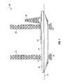
Figure 1 is an elevation view of the present invention where the drilling rig is floating in the water and available to be towed to a well drilling site; -
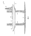
Figure 2 is an elevation view of the present invention where the drilling rig is jacked up out of the water; -
Figure 3 is an elevation view of the first embodiment of the present invention where the drilling rig is partially lowered into the ice/water interface, but still supported by its legs, in a defensive configuration for drilling during potential ice conditions; -
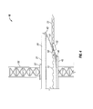
Figure 4 is an enlarged fragmentary elevation view showing one end of the first embodiment of the present invention in theFigure 3 configuration with ice moving against the rig; -
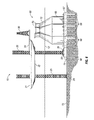
Figure 5 is an elevation view showing the drilling rig moving to a conical piled monopod for drilling down through the conical piled monopod; -
Figure 6 is an elevation view showing the drilling rig arranged over the conical piled monopod to drill down through the conical piled monopod; -
Figure 7 is an elevation view showing the drilling rig arranged adjacent to the conical piled monopod in it ice defensive configuration; and -
Figure 8 is a top view showing the drilling rig positioned to drill down through the conical piled monopod. - Turning now to the detailed description of the preferred arrangement or arrangements of the present invention, it should be understood that the inventive features and concepts may be manifested in other arrangements and that the scope of the invention is not limited to the embodiments described or illustrated. The scope of the invention is intended only to be limited by the scope of the claims that follow.
- As shown in
Figure 1 , an ice worthy jack-up rig is generally indicated by thearrow 10. InFigure 1 , jack-up rig 10 is shown with itshull 20 floating in the sea andlegs 25 in a lifted arrangement where much of the length of thelegs 25 extend above thedeck 21 of thehull 20. On thedeck 21 isderrick 30 mounted to drillingcantilever 24 and with other conventional equipment and systems, facilitate the drill of wells. In the configuration shown inFigure 1 , the jack-up rig 10 may be towed from one drilling site to another and to and from shore bases for maintenance and other shore service. - When the jack-
up rig 10 is towed to a drilling site in generally shallow water, thelegs 25 are lowered through theopenings 27 inhull 20 until thefeet 26 at the bottom ends of thelegs 25 engage theseafloor 15 as shown inFigure 2 . In a preferred embodiment, thefeet 26 are connected tospud cans 28 to secure therig 10 to the seafloor. Once thefeet 26 engage theseafloor 15, jacking rigs withinopenings 27 push thelegs 25 down and therefore, thehull 20 is lifted out of the water. With thehull 20 fully jacked-up and out of the water, any wave action and heavy seas more easily break past thelegs 25 as compared to the effect of waves against a large buoyant object like thehull 20. - When ice begins to form on the
sea surface 12, the risk of an ice floe contacting and damaging thelegs 25 or simply bulldozing the jack-uprig 10 off the drilling site becomes a significant concern for conventional jack-up rigs and such rigs are typically removed from drill sites by the end of the open water season. The ice-worthy jack-up drillingrig 10 of the present invention is designed to resist ice floes by assuming an ice defensive, hull-in-water configuration as shown inFigure 3 . InFigure 3 , ice tends to dampen waves and rough seas, so thesea surface 12 appears less threatening, however, the hazards of the marine environment have only altered, and not lessened. - When the ice-worthy jack-up
rig 10 assumes its ice defensive, hull-in-water configuration, thehull 20 is lowered into the water to contact same, but not to the extent that thehull 20 would begin to float. A significant portion of the weight of therig 10 preferably remains on thelegs 25 to hold the position of therig 10 on the drill site against any pressure an ice flow might bring. Therig 10 is lowered so that inwardly sloped, ice-bendingsurface 41, as best seen inFigure 4 bridges thesea surface 12 to engage any floating ice that may come upon therig 10. - The sloped ice-bending
surface 41 runs fromshoulder 42, which is at the edge of thedeck 26, down toneckline 44.Ice deflector 45 extends downward fromneckline 44. Thus, when an ice floe, such as shown at 51 comes to therig 10, the ice-bendingsurface 41 causes the leading edge of theice floe 51 to submerge under thesea surface 12 and apply a significant bending force that breaks large ice floes into smaller, less damaging, less hazardous bits of ice. For example, it is conceivable that an ice floe being hundreds of feet and maybe miles across could come toward therig 10. If the ice floe is broken into bits that are less than twenty feet in the longest dimension, such bits are able to pass around therig 10 with much less concern. - In
Figure 5 , a conical piled monopod, generally indicated by the numeral 60, has been pre-installed to the seafloor. The conical piledmonopod 60 is a structure that may be used in ice-prone, offshore locations at much lower cost as compared to a conventional gravity based structure (GBS). A conical piledmonopod 60 includes abody 65, abase 67 and atop deck 70. The base 67 preferably has the form of a flange with holes or perforations spaced around the perimeter of the conical piledmonopod 60. Thebase 67 is arranged to rest on theseafloor 15. While the conical piledmonopod 60 rests on the seafloor, the weight of the conical piled monopod is preferably carried by a plurality ofpilings 68 that are driven deep into theseafloor 15 and then attached to the conical piledmonopod 60. It is typical to drive thepilings 68 between about 35 and about 75 meters into the seabed to permanently fix the conical piledmonopod 60 in its offshore location. Thepilings 68 are typically strong, but hollow tubes or pipe like structures that act like long nails and provide a very structurally efficient arrangement for a permanent platform for offshore hydrocarbon drilling and production operations. The pilings have a relatively large diameter of between 1 and 3 meters with a wall thickness of about 2 to 10 cm. One particular advantage of the present invention is that with the weight of the conical piledmonopod 60 supported by thepilings 68, little or no seabed preparation is necessary prior to installation and to the extent there is any seabed preparation, it is principally to create a level seafloor to set the conical piledmonopod 60 onto as thepilings 68 are installed. A seabed comprising soft, muddy materials is not likely to be excavated and replaced with firmer materials. - With the conical piled
monopod 60 supported by thepilings 68, preparation of the seafloor for installation of the conical piledmonopod 60 is minimal or none. Once thepilings 68 are driven into the seafloor and firmly attached to thebase 67, thepilings 68 provide resistance to: (a) forces that cause structures to slide along the seafloor, (b) forces that cause structures to overturn such as forces acting several meters above the base of a structure; and (c) forces that cause vertical movement both upwardly and downwardly. The resistance to both upward and downward motion or movement is important in resisting toppling forces that may be imposed by ice. Thepilings 68 at the front side of the conical piledmonopod 60 resist lifting forces that ice may impose on the upstream side to resist toppling over while thepilings 68 at the far side or back side or downstream side of the conical piledmonopod 60 resist downward motion that would allow the back side to roll deeper into theseafloor 15. Using such long pilings provides a structurally efficient base for year around operations in an ice prone offshore ice environment that must resist ice loads that can be quite substantial. The pilings act like nails that hold the platform in place and are structurally more efficient than in the case of a GBS where resistance to overturning is provided only by the size and weight of the structure. - The length and number of the
pilings 68 will be dictated by the magnitude of the predicted vertical and lateral forces and by the strength of the soil layers into which the pilings are driven. Preferably, the pilings are strategically arranged around the periphery of the base 67 to provide resistance to sliding and toppling forces with maximum structural efficiency. The base may include at least eight and preferably at least 16 pilings, and up to as many as 64 pilings, around the periphery at a spacing that would maximize structural efficiency and create a pile cluster where the number of clusters work together to resist lateral forces and support the conical piledmonopod 60. Thepilings 68 typically extend between 35 and 75 meters into the seabed depending on predicted loads and the strength characteristics of the soil. The conical piledmonopod 60 is shown as an eight sided faceted structure but a round or circular configuration may also be employed. It is preferred that the structure be faceted for ease of fabrication having six, eight, or even 12 sides, preferably all being equal in dimension and where the conical piledmonopod 60 is symmetrical. - The
body 65 of the conical piledmonopod 60 includes a sloped, ice-engagingsurface 72 that extends from below thesea surface 12 to above thesea surface 12 such that ice in the sea, particularly floating ice, engages thebody 65 at the sloped, ice-engagingsurface 72. The ice-engagingsurface 72 extends around the periphery of the conical piledmonopod 60 so that ice from any direction will come into contact with thebody 65 at the ice-engagingsurface 72. The slope of the ice-engagingsurface 72 causes any sheet of ice to rise up the slope and bend to a point of breaking and is typically between 40 degrees and 60 degrees from the horizontal and more preferably about 55 degrees from the horizontal. Broken ice chunks, called rubble, will work their way around thebody 65, driven by the sea current or wind. Above the ice-engagingsurface 72 the conical piled monopod includes a shape to turn away ice that pushes all the way up ice-engagingsurface 72. Adeck 70 is at the top of the conical piledmonopod 60 may be equipped with a drilling template for drilling many wells. - The conical piled
monopod 60 is a substantial structure typically having a dimension ofdeck 70 being more than 75 meters across. While being large and strong, one advantage of a conical piled monopod over a gravity based structure is that it is generally lighter in weight or more particularly, density, prior to any water ballasting. Solid ballast material is generally not needed for a conical piled monopod. While a gravity based structure (GBS) typically has a density of from 0.21 tonnes/m3 to 0.25 tonnes/m3, a conical piled monopod may be constructed to be 0.20 tonnes/m3 down to about 0.18 tonnes/m3. Often, a GBS would need solid ballast to increase its weight to provide resistance to sliding and overturning. By using piles or a cluster ofpilings 68, the conical piledmonopod 60 may be designed to be in lighter weight. The lighter density of a conical piled monopod may also translate into lower fabrication and transportation cost, not including the lower installation cost due to the avoided site preparation costs for preparing the seafloor for a large GBS system and for the high density ballast material often added to a GBS. - While conical piled
monopods 60 may be equipped with a derrick and systems for drilling wells, there is a cost savings if the wells can be drilled by a jack-up rig as the conical piled monopod may be sized somewhat smaller and of course having cost savings on size alone, not to mention the cost savings for all the drilling related equipment and systems. Drilling well through the conical piled monopod with an ice worthy drilling rig such asrig 10 provides additional cost savings in that the rig does not necessarily have to be towed away at the first sign of ice. More wells may be drilled per year with an iceworthy rig 10 that can stay on station longer into the fall when other drill rigs are long gone. - With the conical piled
monopod 60 fixed to thesea floor 15, thedrilling rig 10 moves in as shown inFigure 5 and sets up to drill down through the conical piledmonopod 60 as shown inFigure 6 . In one particular aspect of the present invention aretabs 75 extending out frombase 67 that includepilings 68 to be secured to theseafloor 15. Spudcans 28 closest to the conical piledmonopod 60 are aligned to set into sockets on the top of thetabs 75 and held in place byclasps 78. Thus, therig 10 is provided additional resistance to movement by ice pressure by attaching to the conical piled monopod. This arrangement has been described as an "Ahab Socket" referring to the captain in Moby Dick inserting his peg leg into a knothole in the boat to stabilize himself while hunting whales. - Once secured into the sockets, the
legs 25 of the ice-worthy drilling rig 10, which will be constructed stronger than conventional legs for jack-up rigs will be able to withstand limited ice threats. However, in the event that more significant ice threats present themselves, the ice-worthy drilling rig 10 has the option to stay on location, suspend drilling operations and assume an ice defensive configuration as shown inFigure 7 . In this position, ice that comes into contact with either or both of therig 10 and conical piledmonopod 60 will be broken up and directed to pass around the system. When the ice is abated, drilling may resume and when the ice becomes too thick, therig 10 may be fully removed from the location until the following drilling season. It is the shape of the hull 20 (as well as its strength) that provides ice bending and breaking capabilities and expands the time window for drilling that substantially lowers costs for ice prone locations. While it is preferred that therig 10 sets up adjacent one of the facets of the conical piled monopod as shown inFigure 8 , but may approach from any direction as indicated by 20A. - The
hull 20 preferably has a faceted or multisided shape that provides the advantages of a circular or oval shape, and may be less expensive to construct. The plates that make up the hull would likely be formed of flat sheets and so that the entire structure comprises segments of flat material such as steel would likely require less complication. The ice-breaking surface would preferably extend at least about five meters above the water level, recognizing that water levels shift up and down with tides and storms and perhaps other influences. The height above the water level accommodates ice floes that are quite thick or having ridges that extend well above thesea surface 12, but since the height of theshoulder 42 is well above thesea surface 12, the tall ice floes will be forced down as they come into contact with therig 10. At the same time, thedeck 21 at the top of thehull 20 should be far enough above the water line so that waves are not able to wash across the deck. As such, thedeck 25 is preferred to be at least 7 to 8 meters above thesea surface 12. Conversely, theneckline 42 is preferred to be at least 4 to 8 meters below thesea surface 12 to adequately bend the ice floes to break them up into more harmless bits. Thus, thehull 20 is preferably in the range of 5-16 meters in height from the flat of bottom to thedeck 20, more preferably 8-16 meters or 11-16 meters. - It should also be noted that the
legs 25 and theopenings 27 through which they are connected to thehull 20 are within the perimeter of theice deflector 45 so that the ice floes are less likely to contact the legs while therig 10 is in its defensive ice condition configuration as shown inFigure 3 and sometimes called hull-in-water configuration. Moreover, therig 10 does not have to handle every ice floe threat to significantly add value to oil and gas companies. Ifrig 10 can extend the drilling season by as little as a month, that would be a fifty percent improvement in some ice prone areas and therefore provide a very real cost saving benefit to the industry. - In closing, it should be noted that the discussion of any reference is not an admission that it is prior art to the present invention, especially any reference that may have a publication date after the priority date of this application. At the same time, each and every claim below is hereby incorporated into this detailed description or specification as an additional embodiment of the present invention.
- Although the systems and processes described herein have been described in detail, it should be understood that various changes, substitutions, and alterations can be made without departing from the scope of the invention as defined by the following claims.
Claims (15)
- A system for drilling and producing hydrocarbons in potential ice conditions in offshore areas comprising:a rig (10) having a flotation hull (20) with a relatively flat deck (21) at the upper portion thereof and an ice-bending shape (41) along the lower portion thereof and extending downwardly and inwardly around the periphery of the hull; an ice deflecting portion (45) extending around the perimeter of the bottom of the hull to direct ice (51) around the hull and not under the hull; at least three legs (25) that are positioned within the perimeter of the bottom of the flotation hull (20) wherein the legs are arranged to be lifted up off the seafloor so that the rig may be towed through shallow water and also extend to the sea floor (15) and extend further to lift the hull partially or fully out of the water; and a jack-up device associated with each leg to both lift the leg from the sea bottom so that the ice worthy jack-up rig may float by the buoyancy of the hull and push the legs down to the seafloor and push the hull partially up and out of the water when ice floes threaten the rig and fully out of the water when ice is not present; anda conical piled monopod (60) having a body with a base (67) at the bottom and a top deck (70) at the top, an inclined ice engaging surface (72) around the body extending from a wider lower region to a narrower upper region where the lower region is below the sea surface (12) and the upper region is above the sea surface;wherein the rig (10) is arranged to lift its hull (20) out of the water and drill through the conical piled monopod (60), lower itself into the water to assume an ice defensive position such that ice would contact the ice-bending shape (41) of the rig when thin ice is present, and be moved away when thick ice is present;characterised in that the the ice-bending shape (41) extends from an area of the hull (20) near the level of the deck (21) and extends downwardly near the bottom of the hull, in that the base (67) is attached to pilings (68) that are driven into the seafloor when the conical piled monopod structure is installed for use, and in that the monopod includes tabs (75) with sockets arranged to receive a foot on at least one of the legs (25) to be attached and held in place for drilling through the conical piled monopod (60).
- The system according to claim 1, further including a clasp at the sockets that selectively holds a foot into the socket and, when desired, releases the foot.
- The system according to claim 1 or claim 2, wherein the ice bending surface (41) of the rig is slanted upwardly and outwardly from a smaller dimension neckline (44) to a larger dimension shoulder (42).
- The system according to any preceding claim, wherein the ice bending surface (41) of the rig extends vertically at least 8 to 10 or more meters.
- The system according to claim 4, wherein the angle of the ice-bending surface (41) of the rig is in the range of 30 to 60 degrees from the vertical.
- The system according to any preceding claim, wherein the body of the conical piled monopod (60) is at least 60 meters across and the monopod structure has a density of less then about 0.20 tonnes/m3.
- The system according to any preceding claim, wherein the pilings (68) are greater than or equal to 35 meters below the base.
- The system according to any preceding claim, wherein the pilings (68) are greater than or equal to 50 meters below the base.
- A method for drilling a well in ice prone waters using a system as claimed in any preceding claim, the method comprising:providing a conical piled monopod (60) having a body with a base (67) at the bottom and a top deck (70) at the top and an inclined ice engaging surface (72) around the body extending from a wider lower region to a narrower upper region where the lower region is below the sea surface (12) and the upper region is above the sea surface;providing rig (10) having a flotation hull (20) having a relatively flat deck (21) at the upper portion thereof and an ice-bending shape (41) along the lower portion thereof and an ice deflecting portion (45) extending around the perimeter of the bottom of the hull to direct ice around the hull and not under the hull;providing at least three legs (25) that are positioned within the perimeter of the bottom of the hull;jacking down each leg such that the jacking down of the legs lifts the hull up and fully out of the water when ice is not threatening the rig while the rig is drilling a well on a drill site;lowering the hull (20) into the water into an ice defensive configuration so that the ice-bending shape (41) extends above and below the sea surface to bend ice that comes against the rig to cause the ice to submerge under the water and endure bending forces that break the ice where the ice flows past the rig; anddrilling a well over the side of the deck and down through the conical piled monopod (60);characterised in that the ice-bending shape (41) extends from an area of the hull near the level of the deck (21) and extends downwardly near the bottom of the hull, in that the conical piled monopod (60) includes at least one tab (75) with a socket for receiving and holding a foot of a jack-up drilling rig, and in that the method includes driving pilings (68) into the seafloor and attaching the pilings to the conical piled monopod to fix the conical piled monopod to the sea floor, and in that the legs (25) are jacked down in a manner that at least one foot on the bottom of one of the legs engages the socket on the tab (75) of the conical piled monopod (60) and the remaining feet engage the sea floor or another socket on a tab.
- The method according to claim 9 wherein the step of driving the pilings (68) further comprises driving the pilings having at least a 1 meter diameter at least 35 meters into the sea floor.
- The method according to claim 9 or claim 10 wherein the ice-bending surface (41) extends from a shoulder (42) to a neckline (44) and the step of lowering the hull (20) into the water more particularly comprises lowering the hull into the water so that the neckline (44) is at least 4 meters below the sea surface and the shoulder (42) is at least 7 meters above the sea surface.
- The method according to any of claims 9 to 11 further including the step of raising the hull (20) up out of the water when the threat of ice floes are reduced.
- The method according to any of claims 9 to 12 wherein the step of driving the pilings (68) further comprises driving the pilings having at least a 1.5 meter diameter at least 50 meters into the sea floor.
- The method according to any of claims 9 to 13 wherein the step of driving the pilings (68) further comprises driving the pilings having at least a 2 meter diameter at least 60 meters into the sea floor.
- A method for drilling a well in ice prone waters comprising the use of a rig and conical piled monopod as claimed in any of claims 1 to 8.
Applications Claiming Priority (5)
| Application Number | Priority Date | Filing Date | Title |
|---|---|---|---|
| US40549710P | 2010-10-21 | 2010-10-21 | |
| US41495010P | 2010-11-18 | 2010-11-18 | |
| US13/277,755 US8821071B2 (en) | 2010-11-18 | 2011-10-20 | Conical piled monopod |
| US13/277,791 US20120128426A1 (en) | 2010-10-21 | 2011-10-20 | Ice worthy jack-up drilling unit |
| PCT/US2011/057378 WO2012054891A1 (en) | 2010-10-21 | 2011-10-21 | Ice worthy jack-up drilling unit with conical piled monopod and sockets |
Publications (2)
| Publication Number | Publication Date |
|---|---|
| EP2630303A1 EP2630303A1 (en) | 2013-08-28 |
| EP2630303B1 true EP2630303B1 (en) | 2015-07-22 |
Family
ID=48173979
Family Applications (1)
| Application Number | Title | Priority Date | Filing Date |
|---|---|---|---|
| EP11779048.5A Not-in-force EP2630303B1 (en) | 2010-10-21 | 2011-10-21 | Ice worthy jack-up drilling unit with conical piled monopod and sockets |
Country Status (7)
| Country | Link |
|---|---|
| EP (1) | EP2630303B1 (en) |
| KR (1) | KR20130120463A (en) |
| CN (1) | CN103180513B (en) |
| CA (1) | CA2811946C (en) |
| RU (1) | RU2564711C2 (en) |
| SG (1) | SG189116A1 (en) |
| WO (1) | WO2012054891A1 (en) |
Families Citing this family (2)
| Publication number | Priority date | Publication date | Assignee | Title |
|---|---|---|---|---|
| WO2016192729A1 (en) * | 2015-05-29 | 2016-12-08 | Maersk Drilling A/S | Arctic drilling process |
| CN117846017B (en) * | 2024-01-11 | 2024-09-03 | 江苏长风海洋装备制造有限公司 | Preparation process of high-strength lifting leg pile of offshore booster station |
Family Cites Families (8)
| Publication number | Priority date | Publication date | Assignee | Title |
|---|---|---|---|---|
| US3972199A (en) * | 1972-06-26 | 1976-08-03 | Chevron Research Company | Low adhesional arctic offshore platform |
| CA1230745A (en) * | 1978-03-29 | 1987-12-29 | James C. Pearce | Arctic multi-angle conical structure |
| FI822158A7 (en) * | 1982-06-15 | 1983-12-16 | Waertsilae Oy Ab | Drilling platform. |
| RU2048372C1 (en) * | 1991-01-25 | 1995-11-20 | Борис Борисович Клячкин | Ice breaking device |
| CA2644349C (en) * | 2006-03-30 | 2014-07-08 | Exxonmobil Upstream Research Company | Mobile, year-round arctic drilling system |
| RU2361039C2 (en) * | 2007-02-19 | 2009-07-10 | Виктор Ильич Мищевич | Method for erection of multi-support technological platform |
| CN201172814Y (en) * | 2007-12-04 | 2008-12-31 | 中国石油集团海洋工程有限公司 | Shallow sea self-lifting production testing work platform |
| CN100575613C (en) * | 2008-06-12 | 2009-12-30 | 天津大学 | Active anti-icing device with automatic spiral lift |
-
2011
- 2011-10-21 KR KR1020137010002A patent/KR20130120463A/en not_active Withdrawn
- 2011-10-21 EP EP11779048.5A patent/EP2630303B1/en not_active Not-in-force
- 2011-10-21 WO PCT/US2011/057378 patent/WO2012054891A1/en not_active Ceased
- 2011-10-21 CA CA2811946A patent/CA2811946C/en not_active Expired - Fee Related
- 2011-10-21 RU RU2013123049/03A patent/RU2564711C2/en not_active IP Right Cessation
- 2011-10-21 CN CN201180050455.9A patent/CN103180513B/en not_active Expired - Fee Related
-
2012
- 2012-10-21 SG SG2013022595A patent/SG189116A1/en unknown
Also Published As
| Publication number | Publication date |
|---|---|
| CA2811946C (en) | 2015-06-09 |
| RU2564711C2 (en) | 2015-10-10 |
| CA2811946A1 (en) | 2012-04-26 |
| KR20130120463A (en) | 2013-11-04 |
| RU2013123049A (en) | 2014-11-27 |
| EP2630303A1 (en) | 2013-08-28 |
| SG189116A1 (en) | 2013-05-31 |
| CN103180513A (en) | 2013-06-26 |
| CN103180513B (en) | 2016-06-08 |
| WO2012054891A1 (en) | 2012-04-26 |
Similar Documents
| Publication | Publication Date | Title |
|---|---|---|
| CA2813426C (en) | Ice worthy jack-up drilling unit with pre-loading tension system | |
| US8870497B2 (en) | Ice worthy jack-up drilling unit with conical piled monopod | |
| US8807875B2 (en) | Ice worthy jack-up drilling unit with conical piled monopod and sockets | |
| US20120125688A1 (en) | Ice worthy jack-up drilling unit secured to the seafloor | |
| EP2630305B1 (en) | Ice worthy jack-up drilling unit with gas agitation and leg ice shields | |
| US20120128432A1 (en) | Ice worthy jack-up drilling unit with moon pool for protected drilling in ice | |
| CA2811946C (en) | Ice worthy jack-up drilling unit with conical piled monopod and sockets | |
| CA2812597C (en) | Ice worthy jack-up drilling unit with conical piled monopod | |
| US20120128426A1 (en) | Ice worthy jack-up drilling unit | |
| US8801333B2 (en) | Ice worthy jack-up drilling unit with gas agitation and leg ice shields | |
| US8956081B2 (en) | Ice worthy jack-up drilling unit with gas agitated ice prevention | |
| WO2012054801A1 (en) | Ice worthy jack-up drilling unit secured to the seafloor | |
| CA2804900A1 (en) | Reinforced legs for ice worthy jack-up drilling unit |
Legal Events
| Date | Code | Title | Description |
|---|---|---|---|
| PUAI | Public reference made under article 153(3) epc to a published international application that has entered the european phase |
Free format text: ORIGINAL CODE: 0009012 |
|
| 17P | Request for examination filed |
Effective date: 20130521 |
|
| AK | Designated contracting states |
Kind code of ref document: A1 Designated state(s): AL AT BE BG CH CY CZ DE DK EE ES FI FR GB GR HR HU IE IS IT LI LT LU LV MC MK MT NL NO PL PT RO RS SE SI SK SM TR |
|
| DAX | Request for extension of the european patent (deleted) | ||
| 17Q | First examination report despatched |
Effective date: 20141104 |
|
| GRAP | Despatch of communication of intention to grant a patent |
Free format text: ORIGINAL CODE: EPIDOSNIGR1 |
|
| INTG | Intention to grant announced |
Effective date: 20150409 |
|
| GRAS | Grant fee paid |
Free format text: ORIGINAL CODE: EPIDOSNIGR3 |
|
| GRAA | (expected) grant |
Free format text: ORIGINAL CODE: 0009210 |
|
| AK | Designated contracting states |
Kind code of ref document: B1 Designated state(s): AL AT BE BG CH CY CZ DE DK EE ES FI FR GB GR HR HU IE IS IT LI LT LU LV MC MK MT NL NO PL PT RO RS SE SI SK SM TR |
|
| REG | Reference to a national code |
Ref country code: GB Ref legal event code: FG4D |
|
| REG | Reference to a national code |
Ref country code: CH Ref legal event code: EP |
|
| REG | Reference to a national code |
Ref country code: IE Ref legal event code: FG4D |
|
| REG | Reference to a national code |
Ref country code: AT Ref legal event code: REF Ref document number: 738011 Country of ref document: AT Kind code of ref document: T Effective date: 20150815 |
|
| REG | Reference to a national code |
Ref country code: NL Ref legal event code: T3 |
|
| REG | Reference to a national code |
Ref country code: DE Ref legal event code: R096 Ref document number: 602011018068 Country of ref document: DE |
|
| PGFP | Annual fee paid to national office [announced via postgrant information from national office to epo] |
Ref country code: NO Payment date: 20150925 Year of fee payment: 5 Ref country code: GB Payment date: 20150924 Year of fee payment: 5 |
|
| REG | Reference to a national code |
Ref country code: NO Ref legal event code: T2 Effective date: 20150722 |
|
| REG | Reference to a national code |
Ref country code: AT Ref legal event code: MK05 Ref document number: 738011 Country of ref document: AT Kind code of ref document: T Effective date: 20150722 |
|
| REG | Reference to a national code |
Ref country code: LT Ref legal event code: MG4D |
|
| PG25 | Lapsed in a contracting state [announced via postgrant information from national office to epo] |
Ref country code: LT Free format text: LAPSE BECAUSE OF FAILURE TO SUBMIT A TRANSLATION OF THE DESCRIPTION OR TO PAY THE FEE WITHIN THE PRESCRIBED TIME-LIMIT Effective date: 20150722 Ref country code: GR Free format text: LAPSE BECAUSE OF FAILURE TO SUBMIT A TRANSLATION OF THE DESCRIPTION OR TO PAY THE FEE WITHIN THE PRESCRIBED TIME-LIMIT Effective date: 20151023 Ref country code: LV Free format text: LAPSE BECAUSE OF FAILURE TO SUBMIT A TRANSLATION OF THE DESCRIPTION OR TO PAY THE FEE WITHIN THE PRESCRIBED TIME-LIMIT Effective date: 20150722 Ref country code: FI Free format text: LAPSE BECAUSE OF FAILURE TO SUBMIT A TRANSLATION OF THE DESCRIPTION OR TO PAY THE FEE WITHIN THE PRESCRIBED TIME-LIMIT Effective date: 20150722 |
|
| PG25 | Lapsed in a contracting state [announced via postgrant information from national office to epo] |
Ref country code: ES Free format text: LAPSE BECAUSE OF FAILURE TO SUBMIT A TRANSLATION OF THE DESCRIPTION OR TO PAY THE FEE WITHIN THE PRESCRIBED TIME-LIMIT Effective date: 20150722 Ref country code: AT Free format text: LAPSE BECAUSE OF FAILURE TO SUBMIT A TRANSLATION OF THE DESCRIPTION OR TO PAY THE FEE WITHIN THE PRESCRIBED TIME-LIMIT Effective date: 20150722 Ref country code: RS Free format text: LAPSE BECAUSE OF FAILURE TO SUBMIT A TRANSLATION OF THE DESCRIPTION OR TO PAY THE FEE WITHIN THE PRESCRIBED TIME-LIMIT Effective date: 20150722 Ref country code: PL Free format text: LAPSE BECAUSE OF FAILURE TO SUBMIT A TRANSLATION OF THE DESCRIPTION OR TO PAY THE FEE WITHIN THE PRESCRIBED TIME-LIMIT Effective date: 20150722 Ref country code: IS Free format text: LAPSE BECAUSE OF FAILURE TO SUBMIT A TRANSLATION OF THE DESCRIPTION OR TO PAY THE FEE WITHIN THE PRESCRIBED TIME-LIMIT Effective date: 20151122 Ref country code: SE Free format text: LAPSE BECAUSE OF FAILURE TO SUBMIT A TRANSLATION OF THE DESCRIPTION OR TO PAY THE FEE WITHIN THE PRESCRIBED TIME-LIMIT Effective date: 20150722 Ref country code: PT Free format text: LAPSE BECAUSE OF FAILURE TO SUBMIT A TRANSLATION OF THE DESCRIPTION OR TO PAY THE FEE WITHIN THE PRESCRIBED TIME-LIMIT Effective date: 20151123 Ref country code: HR Free format text: LAPSE BECAUSE OF FAILURE TO SUBMIT A TRANSLATION OF THE DESCRIPTION OR TO PAY THE FEE WITHIN THE PRESCRIBED TIME-LIMIT Effective date: 20150722 |
|
| PGFP | Annual fee paid to national office [announced via postgrant information from national office to epo] |
Ref country code: NL Payment date: 20150923 Year of fee payment: 5 |
|
| REG | Reference to a national code |
Ref country code: DE Ref legal event code: R097 Ref document number: 602011018068 Country of ref document: DE |
|
| PG25 | Lapsed in a contracting state [announced via postgrant information from national office to epo] |
Ref country code: CZ Free format text: LAPSE BECAUSE OF FAILURE TO SUBMIT A TRANSLATION OF THE DESCRIPTION OR TO PAY THE FEE WITHIN THE PRESCRIBED TIME-LIMIT Effective date: 20150722 Ref country code: EE Free format text: LAPSE BECAUSE OF FAILURE TO SUBMIT A TRANSLATION OF THE DESCRIPTION OR TO PAY THE FEE WITHIN THE PRESCRIBED TIME-LIMIT Effective date: 20150722 Ref country code: DK Free format text: LAPSE BECAUSE OF FAILURE TO SUBMIT A TRANSLATION OF THE DESCRIPTION OR TO PAY THE FEE WITHIN THE PRESCRIBED TIME-LIMIT Effective date: 20150722 Ref country code: IT Free format text: LAPSE BECAUSE OF FAILURE TO SUBMIT A TRANSLATION OF THE DESCRIPTION OR TO PAY THE FEE WITHIN THE PRESCRIBED TIME-LIMIT Effective date: 20150722 Ref country code: SK Free format text: LAPSE BECAUSE OF FAILURE TO SUBMIT A TRANSLATION OF THE DESCRIPTION OR TO PAY THE FEE WITHIN THE PRESCRIBED TIME-LIMIT Effective date: 20150722 |
|
| REG | Reference to a national code |
Ref country code: DE Ref legal event code: R119 Ref document number: 602011018068 Country of ref document: DE |
|
| PLBE | No opposition filed within time limit |
Free format text: ORIGINAL CODE: 0009261 |
|
| STAA | Information on the status of an ep patent application or granted ep patent |
Free format text: STATUS: NO OPPOSITION FILED WITHIN TIME LIMIT |
|
| PG25 | Lapsed in a contracting state [announced via postgrant information from national office to epo] |
Ref country code: LU Free format text: LAPSE BECAUSE OF FAILURE TO SUBMIT A TRANSLATION OF THE DESCRIPTION OR TO PAY THE FEE WITHIN THE PRESCRIBED TIME-LIMIT Effective date: 20151021 Ref country code: RO Free format text: LAPSE BECAUSE OF FAILURE TO SUBMIT A TRANSLATION OF THE DESCRIPTION OR TO PAY THE FEE WITHIN THE PRESCRIBED TIME-LIMIT Effective date: 20150722 |
|
| REG | Reference to a national code |
Ref country code: CH Ref legal event code: PL |
|
| 26N | No opposition filed |
Effective date: 20160425 |
|
| PG25 | Lapsed in a contracting state [announced via postgrant information from national office to epo] |
Ref country code: MC Free format text: LAPSE BECAUSE OF FAILURE TO SUBMIT A TRANSLATION OF THE DESCRIPTION OR TO PAY THE FEE WITHIN THE PRESCRIBED TIME-LIMIT Effective date: 20150722 |
|
| REG | Reference to a national code |
Ref country code: IE Ref legal event code: MM4A |
|
| PG25 | Lapsed in a contracting state [announced via postgrant information from national office to epo] |
Ref country code: DE Free format text: LAPSE BECAUSE OF NON-PAYMENT OF DUE FEES Effective date: 20160503 Ref country code: CH Free format text: LAPSE BECAUSE OF NON-PAYMENT OF DUE FEES Effective date: 20151031 Ref country code: LI Free format text: LAPSE BECAUSE OF NON-PAYMENT OF DUE FEES Effective date: 20151031 |
|
| REG | Reference to a national code |
Ref country code: FR Ref legal event code: ST Effective date: 20160630 |
|
| PG25 | Lapsed in a contracting state [announced via postgrant information from national office to epo] |
Ref country code: SI Free format text: LAPSE BECAUSE OF FAILURE TO SUBMIT A TRANSLATION OF THE DESCRIPTION OR TO PAY THE FEE WITHIN THE PRESCRIBED TIME-LIMIT Effective date: 20150722 Ref country code: FR Free format text: LAPSE BECAUSE OF NON-PAYMENT OF DUE FEES Effective date: 20151102 |
|
| PG25 | Lapsed in a contracting state [announced via postgrant information from national office to epo] |
Ref country code: IE Free format text: LAPSE BECAUSE OF NON-PAYMENT OF DUE FEES Effective date: 20151021 |
|
| PG25 | Lapsed in a contracting state [announced via postgrant information from national office to epo] |
Ref country code: BE Free format text: LAPSE BECAUSE OF FAILURE TO SUBMIT A TRANSLATION OF THE DESCRIPTION OR TO PAY THE FEE WITHIN THE PRESCRIBED TIME-LIMIT Effective date: 20150722 |
|
| REG | Reference to a national code |
Ref country code: NO Ref legal event code: MMEP |
|
| PG25 | Lapsed in a contracting state [announced via postgrant information from national office to epo] |
Ref country code: BG Free format text: LAPSE BECAUSE OF FAILURE TO SUBMIT A TRANSLATION OF THE DESCRIPTION OR TO PAY THE FEE WITHIN THE PRESCRIBED TIME-LIMIT Effective date: 20150722 Ref country code: HU Free format text: LAPSE BECAUSE OF FAILURE TO SUBMIT A TRANSLATION OF THE DESCRIPTION OR TO PAY THE FEE WITHIN THE PRESCRIBED TIME-LIMIT; INVALID AB INITIO Effective date: 20111021 Ref country code: SM Free format text: LAPSE BECAUSE OF FAILURE TO SUBMIT A TRANSLATION OF THE DESCRIPTION OR TO PAY THE FEE WITHIN THE PRESCRIBED TIME-LIMIT Effective date: 20150722 |
|
| REG | Reference to a national code |
Ref country code: NL Ref legal event code: MM Effective date: 20161101 |
|
| GBPC | Gb: european patent ceased through non-payment of renewal fee |
Effective date: 20161021 |
|
| PG25 | Lapsed in a contracting state [announced via postgrant information from national office to epo] |
Ref country code: CY Free format text: LAPSE BECAUSE OF FAILURE TO SUBMIT A TRANSLATION OF THE DESCRIPTION OR TO PAY THE FEE WITHIN THE PRESCRIBED TIME-LIMIT Effective date: 20150722 |
|
| PG25 | Lapsed in a contracting state [announced via postgrant information from national office to epo] |
Ref country code: NO Free format text: LAPSE BECAUSE OF NON-PAYMENT OF DUE FEES Effective date: 20161031 Ref country code: GB Free format text: LAPSE BECAUSE OF NON-PAYMENT OF DUE FEES Effective date: 20161021 |
|
| PG25 | Lapsed in a contracting state [announced via postgrant information from national office to epo] |
Ref country code: MT Free format text: LAPSE BECAUSE OF FAILURE TO SUBMIT A TRANSLATION OF THE DESCRIPTION OR TO PAY THE FEE WITHIN THE PRESCRIBED TIME-LIMIT Effective date: 20150722 Ref country code: NL Free format text: LAPSE BECAUSE OF NON-PAYMENT OF DUE FEES Effective date: 20161101 |
|
| PG25 | Lapsed in a contracting state [announced via postgrant information from national office to epo] |
Ref country code: TR Free format text: LAPSE BECAUSE OF FAILURE TO SUBMIT A TRANSLATION OF THE DESCRIPTION OR TO PAY THE FEE WITHIN THE PRESCRIBED TIME-LIMIT Effective date: 20150722 Ref country code: MK Free format text: LAPSE BECAUSE OF FAILURE TO SUBMIT A TRANSLATION OF THE DESCRIPTION OR TO PAY THE FEE WITHIN THE PRESCRIBED TIME-LIMIT Effective date: 20150722 |
|
| PG25 | Lapsed in a contracting state [announced via postgrant information from national office to epo] |
Ref country code: AL Free format text: LAPSE BECAUSE OF FAILURE TO SUBMIT A TRANSLATION OF THE DESCRIPTION OR TO PAY THE FEE WITHIN THE PRESCRIBED TIME-LIMIT Effective date: 20150722 |