EP2629506A1 - Two-step brightness adjustment in around-view systems - Google Patents
Two-step brightness adjustment in around-view systems Download PDFInfo
- Publication number
- EP2629506A1 EP2629506A1 EP12155650.0A EP12155650A EP2629506A1 EP 2629506 A1 EP2629506 A1 EP 2629506A1 EP 12155650 A EP12155650 A EP 12155650A EP 2629506 A1 EP2629506 A1 EP 2629506A1
- Authority
- EP
- European Patent Office
- Prior art keywords
- images
- brightness
- camera
- image
- cameras
- Prior art date
- Legal status (The legal status is an assumption and is not a legal conclusion. Google has not performed a legal analysis and makes no representation as to the accuracy of the status listed.)
- Withdrawn
Links
- 238000012937 correction Methods 0.000 claims description 23
- 238000000034 method Methods 0.000 claims description 20
- 238000012800 visualization Methods 0.000 claims description 3
- 230000008569 process Effects 0.000 description 4
- 238000012935 Averaging Methods 0.000 description 3
- 238000012545 processing Methods 0.000 description 3
- 230000007704 transition Effects 0.000 description 3
- 238000013461 design Methods 0.000 description 2
- 238000012986 modification Methods 0.000 description 2
- 230000004048 modification Effects 0.000 description 2
- 241001300198 Caperonia palustris Species 0.000 description 1
- 235000000384 Veronica chamaedrys Nutrition 0.000 description 1
- 238000004364 calculation method Methods 0.000 description 1
- 230000001010 compromised effect Effects 0.000 description 1
- 238000007596 consolidation process Methods 0.000 description 1
- 238000003702 image correction Methods 0.000 description 1
- 230000006872 improvement Effects 0.000 description 1
- 238000012544 monitoring process Methods 0.000 description 1
Images


Classifications
-
- H—ELECTRICITY
- H04—ELECTRIC COMMUNICATION TECHNIQUE
- H04N—PICTORIAL COMMUNICATION, e.g. TELEVISION
- H04N23/00—Cameras or camera modules comprising electronic image sensors; Control thereof
- H04N23/60—Control of cameras or camera modules
- H04N23/66—Remote control of cameras or camera parts, e.g. by remote control devices
-
- H—ELECTRICITY
- H04—ELECTRIC COMMUNICATION TECHNIQUE
- H04N—PICTORIAL COMMUNICATION, e.g. TELEVISION
- H04N23/00—Cameras or camera modules comprising electronic image sensors; Control thereof
- H04N23/70—Circuitry for compensating brightness variation in the scene
- H04N23/73—Circuitry for compensating brightness variation in the scene by influencing the exposure time
-
- H—ELECTRICITY
- H04—ELECTRIC COMMUNICATION TECHNIQUE
- H04N—PICTORIAL COMMUNICATION, e.g. TELEVISION
- H04N23/00—Cameras or camera modules comprising electronic image sensors; Control thereof
- H04N23/60—Control of cameras or camera modules
- H04N23/698—Control of cameras or camera modules for achieving an enlarged field of view, e.g. panoramic image capture
-
- H—ELECTRICITY
- H04—ELECTRIC COMMUNICATION TECHNIQUE
- H04N—PICTORIAL COMMUNICATION, e.g. TELEVISION
- H04N23/00—Cameras or camera modules comprising electronic image sensors; Control thereof
- H04N23/90—Arrangement of cameras or camera modules, e.g. multiple cameras in TV studios or sports stadiums
Definitions
- the present invention relates to around-view camera systems, in particular for the use in connection with parking assistance systems in automobiles.
- a vehicle includes a side-view mirror and a rear-view mirror in order to enable a driver to overlook the surroundings of the vehicle.
- a "blind spot” i.e. an area out of the driver's vision
- additional mirrors may be attached to the vehicle body.
- around-view camera systems have been suggested.
- One such system is described, for example, in the publication US 2010/0245577 A1 . Nissan advertises such a system under the name "Around View Monitor".
- Existing around view camera systems use multiple cameras (e.g., front-view camera, rear-view camera, and left and right side-view cameras) to provide different images covering (almost completely) the area directly surrounding the vehicle.
- the cameras may be equipped with wide-angle lenses (sometimes called "fish-eyes").
- the images captured by the individual cameras are consolidated to one single "overall image” covering the surroundings of the vehicle.
- Such consolidation is usually achieved using an image processing unit executing appropriate image-stitching algorithms which must accomplish the image-processing task in real time in order to provide live images.
- the brightness of the individual images may significantly differ, particularly when the sun is shining and the vehicle casts shadows into the field of view of some of the cameras used.
- the system comprises at least two cameras providing images covering different fields of view of an environment.
- Each camera is configured to capture images using an adjustable exposure time.
- an exposure time control unit is provided that is configured to determine, for each camera, at least one brightness parameter from image data provided by the camera.
- the exposure time control unit is further configured to control the exposure times of the individual cameras such that the brightness parameter(s) determined for a first camera at least approximately match(es) corresponding brightness parameter(s) determined for a second camera.
- the method comprises capturing images with each camera using an adjustable exposure time and adjusting the exposure times. Adjusting the exposure times includes determining, for each camera, at least one brightness parameter from image data provided by the respective camera and, controlling the exposure times of the individual cameras such that the brightness parameter(s) determined for a first camera at least approximately match(es) (a) corresponding brightness parameter(s) determined for a second camera.
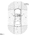
- FIG. 1 schematically illustrates a "bird-eye" view (top view) of a vehicle 10 including a plurality of camera devices 11, 12, 13, and 14 for monitoring the surroundings of the vehicle.
- the camera devices are equipped with a "fish-eye” lens (an ultra wide-angle lens) so as to achieve a wide field of view.
- a front camera 11, two side cameras 12 and 14 and a rear camera 13 are provided at the vehicle, whereby the field of view (denoted as A, B, C, D in FIG. 1 ) of each camera covers a different part of the vehicle's surroundings.
- the cameras are configured in such a manner that the fields of view of two adjacent (neighboring) cameras overlap.
- the fields of view (B and D) of the side cameras 12 and 14 are illustrated in FIG. 1 by the areas hatched with dash-dotted lines, whereas the fields of view (A and C) of the front and rear camera 11, 13 are illustrated by the areas hatched with solid lines.
- the overlapping part of two fields of view has both hatch patterns.
- the camera devices may include, for example, a CCD or a CMOS image sensor and suitable camera lenses.
- the front camera 11 may be arranged, for example, at a front part of the vehicle 10 so as to provide an image of the area A extending to the front of the vehicle.
- the side cameras 12 and 14 may be arranged at a side mirror of the vehicle 10 so as to provide images of the areas B and D extending to the right and left of the vehicle, respectively.
- the rear camera is arranged to capture a view of the area D extending to the rear of the vehicle.
- the views captured by two neighboring cameras overlap. That is, the marginal regions of the images provided by two neighboring cameras (i.e. cameras 11 and 12, cameras 12 and 13, cameras 13 and 14, and cameras 14 and 11) cover the same segments of the vehicle's surroundings.
- FIG. 2 illustrates the concept and the structure of a common ("global") exposure time control applied to all cameras 11, 12, 13, and 14 of the around view system.
- the same part of the surrounding area in the regions where the fields of view of two cameras overlap
- the images are stitched together to one "overall image"
- the abrupt brightness changes are visible in the image regions of transition between two individual images.
- a two-step process is used.
- the exposure times of the individual cameras are adjusted such that one or more brightness parameters determined for a one camera at least approximately match one or more corresponding brightness parameters determined for an adjacent camera.
- two cameras are regarded as adjacent when their respective fields of view partially overlap, as illustrated in FIG. 1 .
- Those parts of the images captured by two adjacent cameras which represent the same piece of environment are referred to as corresponding "marginal regions" of the two respective images.
- a brightness parameter which may be determined for each individual camera, may represent the brightness (i.e. a numeric value measured for each individual pixel of a camera) of one or more pixels of one image captured by the respective camera.
- the current brightness parameter for camera 13 may be determined by averaging the brightness of the pixels which are located within a defined sub-image of the image currently captured by camera 13. In the illustration of FIG. 3 this sub-image is denoted as frame F13.
- frame F13 the same situation is shown for the left camera 14.
- the exposure times of the cameras 11, 12, 13, 14 are adjusted such that the brightness parameter(s) determined for the individual cameras 11, 12, 13, 14 (e.g. the average brightness of the pixels within the frames F11,F12, F13, F14 corresponding to the respectively captured images) are approximately equal.
- the first step of the two-step process results in images which have approximately equal average brightness values.
- the transitions between the individual images remain visible and thus the image quality still requires improvement, which can be done in a second step of the two-step process explained below.
- the brightness of the captured images is manipulated using interpolated gray scale images (e.g. a kind of gray wedges) to correct the pixel values (i.e. the brightness of the pixels) such that the brightness of pre-defined image regions in the marginal region of each image matches the brightness of corresponding image regions of corresponding marginal regions of adjacent images.
- corresponding image regions are regarded as representing the same part of the surrounding area.
- brightness values are calculated which represent the (e.g. average) brightness of the image regions I A1 , I A2 , I A3 , and I A4 located in the marginal region of the image A provided by the front camera 11. Furthermore, the brightness values of the corresponding image regions I B , and I B2 in the marginal region of the image B (right camera) and the image regions I D3 and I D4 in the marginal region of the image D (left camera) are determined.
- each corresponding pair of image regions I A1 and I B1 , I A2 and I B2 , I A3 and I D3 , and I A4 and I D4 represents the same part of the surrounding area.
- a corresponding local brightness correction factor I A1 ', I A2 ', I A3 ', I A4 ', etc is calculated.
- the local brightness correction factors are calculated such that the corrected images have approximately the same local (e.g.
- a predefined number (four in the present example) of local correction factors are determined for each image.
- a gray scale image A' (a kind of two-dimensional "gray wedge") can be calculated, e.g. using bilinear interpolation.
- This gray scale image A' can be used to scale the brightness values composing the image A. The same procedure is performed for each image A, B, C, D provided by the respective cameras, 11, 12, 13, and 14.
- this scaling is performed by the intensity modulation unit 30 which- in a simple exemplary implementation - merely calculates the product of the image A and the corresponding gray scale image A' (and analogously for the other images).
- the resulting brightness corrected images may be provided to a visualization unit 40 which performs a simple image stitching algorithm without the need for sophisticated brightness adjustment.
- An around view does not necessarily need to cover a 360 degree panorama view.
- panorama images are provided based on images captured by at least two cameras (cf. cameras 11 to 14 in FiGs. 1 and 2 ), whereby the images of different cameras cover different fields of view (cf. views A to D in FiGs. 2 and 4 ) of an environment.
- Each camera 11, 12, 13, and 14 is configured to capture images A, B, C, and D using an adjustable exposure time T 11 , T 12 , T 12 , and T 14 , respectively.
- an exposure time control unit 20 is configured to determine, for each camera 11, 12, 13, and 14, at least one brightness parameter from image data provided by the respective camera.
- the exposure time control unit 20 is further configured to control the exposure times of the individual cameras 11, 12, 13, and 14, such that the brightness parameter(s) determined for a first camera (e.g. camera 11) at least approximately match(es) corresponding brightness parameter(s) determined for at least a second camera (e.g. cameras 12 to 14).
- the brightness parameters may represent the average brightness of one or more sub-images of the camera images.
- the around view system may further include an intensity modulation unit 30 which is configured to adjust the brightness of each image A, B, C, and D locally in such a manner that - after the adjustment - local brightness values calculated for corresponding image regions (see, e.g., regions I A1 and I B1 in FIG. 4 ) of images provided by two adjacent cameras (camera 11 and 12 in the present example) at least approximately match.
- the local brightness value may again be calculated by averaging the brightness of the pixels located within the mentioned image regions (i.e. calculating the average brightness of regions I A1 , I A2 , etc.).
- gray scale images A', B', C', and D' are provided for locally adjusting the brightness of the images A, B, C, and D, respectively, by multiplying the images A, B, C, and D with corresponding gray scale images A', B', C', and D'.
- the gray scale images A', B', C', and D' are calculated using interpolation and previously determined local brightness correction factors, which are calculated for defined image regions (I A1 to I A4 , I B1 to I B4 , etc.) located in the marginal regions of the images.
- the brightness correction factors are calculated such that - after correction - local brightness values calculated for corresponding image regions of images provided by two adjacent cameras at least approximately match.
- a visualization unit 40 is provided for stitching the (intensity modulated) images provided by the cameras together so as to generate one around view image.
- Another aspect of the invention relates to a method for generating around view images, whereby at least two cameras (cameras 11 to 14 in the example of FIG. 1 ) are used for providing images covering different fields of view (cf. views A to D in FIG. 1 , 2 and 4 ).
- the method comprises capturing images A, B, C, or D with each camera 11,12, 13, and 14 using an adjustable exposure time T 11 , T 12 , T 13 , and T 14 .
- Adjusting the exposure times T 11 , T 12 , T 13 , and T 14 includes determining, for each camera, at least one brightness parameter from image data provided by the respective camera and, further, controlling the exposure times T 11 , T 12 , T 13 , and T 14 of the individual cameras 11,12, 13, and 14 such that the brightness parameter(s) determined for a first camera at least approximately match(es) (a) corresponding brightness parameter(s) determined for at least a second camera.
- the method may further include adjusting the brightness of each image (see FIG. 4 , images A to D) locally in such a manner that - after the adjustment - local brightness values calculated for corresponding image regions (see FIG. 4 , e.g., regions I A1 and I B1 ) of images provided by two adjacent cameras (cameras 11 and 12 in the present example) at least approximately match.
- Two corresponding image regions of images provided by two adjacent cameras are located in marginal regions of the respective images and represent the same piece of environment.
- local brightness correction factors are determined for defined image regions (e.g., I A1 , I B1 , etc.) located in the marginal regions of the images.
- the brightness correction factors are calculated such that - after the adjustment - local brightness values, which can be calculated for corresponding image regions of images provided by two adjacent cameras, at least approximately match. Further, gray scale images A', B', C', and D' are calculated for locally adjusting the brightness of the image A, B, C, and D, respectively, using interpolation and the previously determined local brightness correction factors. The image provided by the respective camera and the corresponding gray scale image are then multiplied for adjusting the brightness.
- the calculation of a brightness parameter for the image region (e.g. regions I A1 ) of a first image (e.g., image A) includes calculating a brightness parameter for the corresponding image region (regions I B1 in the present example) of a second image (image B in the present example) provided by an adjacent camera, and calculating the local brightness correction factor for the two corresponding image regions (e.g. I A1 and I B1 ) such that the corresponding products of correction factors and brightness parameter are approximately equal.
Landscapes
- Engineering & Computer Science (AREA)
- Multimedia (AREA)
- Signal Processing (AREA)
- Image Processing (AREA)
- Studio Devices (AREA)
- Stereoscopic And Panoramic Photography (AREA)
Abstract
An around view system is described. In accordance with a first example of the invention the system comprises at least two cameras providing images covering different fields of view of an environment. Each camera is configured to capture images using an adjustable exposure time. Further, an exposure time control unit is provided that is configured to determine, for each camera, at least one brightness parameter from image data provided by the camera. The exposure time control unit is further configured to control the exposure times of the individual cameras such that the brightness parameter(s) determined for a first camera at least approximately match(es) corresponding brightness parameter(s) determined for a second camera.
Description
- The present invention relates to around-view camera systems, in particular for the use in connection with parking assistance systems in automobiles.
- Generally, a vehicle includes a side-view mirror and a rear-view mirror in order to enable a driver to overlook the surroundings of the vehicle. However, there exists a "blind spot" (i.e. an area out of the driver's vision) which the driver may not be able to see when using the mirrors. In order to minimize the area concealed by the blind spot, additional mirrors may be attached to the vehicle body. However, even by using such additional mirrors provided at the vehicle body, it is not easy to completely eliminate the blind spot(s). Furthermore, in the case where such a mirror is attached to the vehicle body, the design of the vehicle may be compromised. To alleviate the problem, around-view camera systems have been suggested. One such system is described, for example, in the publication
US 2010/0245577 A1 . Nissan advertises such a system under the name "Around View Monitor". - Existing around view camera systems use multiple cameras (e.g., front-view camera, rear-view camera, and left and right side-view cameras) to provide different images covering (almost completely) the area directly surrounding the vehicle. In order to maximize the field of view of the individual cameras the cameras may be equipped with wide-angle lenses (sometimes called "fish-eyes"). The images captured by the individual cameras are consolidated to one single "overall image" covering the surroundings of the vehicle. Such consolidation is usually achieved using an image processing unit executing appropriate image-stitching algorithms which must accomplish the image-processing task in real time in order to provide live images. However, the brightness of the individual images may significantly differ, particularly when the sun is shining and the vehicle casts shadows into the field of view of some of the cameras used.
- Stitching together images of significantly different brightness may lead to a sub-optimal quality of the resulting overall image. Furthermore, due to the real-time requirements many common image-stitching algorithms cannot be used unless very expensive computation hardware is provided (which is usually undesired in automotive applications). Thus, there is a general need for an around view system which is able to generate overall images from the images captured by the individual cameras and which ensures that the transitions between the individual images are smooth and scarcely visible in the consolidated overall image. Furthermore, the hardware requirements should be kept to a minimum.
- An around view system is described. In accordance with a first example of the invention, the system comprises at least two cameras providing images covering different fields of view of an environment. Each camera is configured to capture images using an adjustable exposure time. Furthermore, an exposure time control unit is provided that is configured to determine, for each camera, at least one brightness parameter from image data provided by the camera. The exposure time control unit is further configured to control the exposure times of the individual cameras such that the brightness parameter(s) determined for a first camera at least approximately match(es) corresponding brightness parameter(s) determined for a second camera.
- Furthermore, a method for generating around view images is described, whereby at least two cameras are used for providing images covering different fields of view. In accordance with one example of the invention, the method comprises capturing images with each camera using an adjustable exposure time and adjusting the exposure times. Adjusting the exposure times includes determining, for each camera, at least one brightness parameter from image data provided by the respective camera and, controlling the exposure times of the individual cameras such that the brightness parameter(s) determined for a first camera at least approximately match(es) (a) corresponding brightness parameter(s) determined for a second camera.
- The invention can be better understood with reference to the following drawings and descriptions. The components in the figures are not necessarily to scale, instead emphasis is placed on illustrating the principles of the invention. Moreover, in the figures like reference numerals designate corresponding parts. In the drawings:
- FIG. 1
- illustrates an around view system including four cameras arranged on each side (front, right, left, rear) of a vehicle;
- FIG. 2
- illustrates the concept of a common exposure time control for all cameras of the around view system;
- FIG. 3
- illustrates one example of determining a brightness parameter by averaging; and
- FIG. 4
- illustrates one example of brightness adjustment and image stitching.
- An example of an around view system for an automobile is described in the following with reference to the drawings.
FIG. 1 schematically illustrates a "bird-eye" view (top view) of avehicle 10 including a plurality ofcamera devices front camera 11, twoside cameras rear camera 13 are provided at the vehicle, whereby the field of view (denoted as A, B, C, D inFIG. 1 ) of each camera covers a different part of the vehicle's surroundings. The cameras are configured in such a manner that the fields of view of two adjacent (neighboring) cameras overlap. The fields of view (B and D) of theside cameras FIG. 1 by the areas hatched with dash-dotted lines, whereas the fields of view (A and C) of the front andrear camera - The
front camera 11 may be arranged, for example, at a front part of thevehicle 10 so as to provide an image of the area A extending to the front of the vehicle. Theside cameras vehicle 10 so as to provide images of the areas B and D extending to the right and left of the vehicle, respectively. The rear camera is arranged to capture a view of the area D extending to the rear of the vehicle. As shown inFIG. 1 , the views captured by two neighboring cameras overlap. That is, the marginal regions of the images provided by two neighboring cameras (i.e.cameras cameras cameras cameras 14 and 11) cover the same segments of the vehicle's surroundings. -
FIG. 2 illustrates the concept and the structure of a common ("global") exposure time control applied to allcameras - To eliminate or at least alleviate this problem a two-step process is used. In a first step, the exposure times of the individual cameras are adjusted such that one or more brightness parameters determined for a one camera at least approximately match one or more corresponding brightness parameters determined for an adjacent camera. Generally, two cameras are regarded as adjacent when their respective fields of view partially overlap, as illustrated in
FIG. 1 . Those parts of the images captured by two adjacent cameras which represent the same piece of environment are referred to as corresponding "marginal regions" of the two respective images. - A brightness parameter, which may be determined for each individual camera, may represent the brightness (i.e. a numeric value measured for each individual pixel of a camera) of one or more pixels of one image captured by the respective camera. For example the current brightness parameter for
camera 13 may be determined by averaging the brightness of the pixels which are located within a defined sub-image of the image currently captured bycamera 13. In the illustration ofFIG. 3 this sub-image is denoted as frame F13. The same situation is shown for theleft camera 14. To summarize the function of the exposuretime control unit 20 illustrated inFIG. 2 , the exposure times of thecameras individual cameras - The first step of the two-step process results in images which have approximately equal average brightness values. However, when stitching the images together without performing additional image processing the transitions between the individual images remain visible and thus the image quality still requires improvement, which can be done in a second step of the two-step process explained below. According to one example of the invention, the brightness of the captured images is manipulated using interpolated gray scale images (e.g. a kind of gray wedges) to correct the pixel values (i.e. the brightness of the pixels) such that the brightness of pre-defined image regions in the marginal region of each image matches the brightness of corresponding image regions of corresponding marginal regions of adjacent images. In this context corresponding image regions are regarded as representing the same part of the surrounding area. This simple-to-implement image correction is further illustrated with reference to
FIG. 4 . - The following description refers to the brightness correction of the image A provided by the
front camera 11. However, the same procedure is also applicable for the images provided by theother cameras FIG. 4 , brightness values are calculated which represent the (e.g. average) brightness of the image regions IA1, IA2, IA3, and IA4 located in the marginal region of the image A provided by thefront camera 11. Furthermore, the brightness values of the corresponding image regions IB, and IB2 in the marginal region of the image B (right camera) and the image regions ID3 and ID4 in the marginal region of the image D (left camera) are determined. It should be noted that each corresponding pair of image regions IA1 and IB1, IA2 and IB2, IA3 and ID3, and IA4 and ID4, respectively, represents the same part of the surrounding area. For each one of the considered image regions IA1, IA2, IA3, IA4, etc. a corresponding local brightness correction factor IA1', IA2', IA3', IA4', etc is calculated. The local brightness correction factors are calculated such that the corrected images have approximately the same local (e.g. average) brightness value in corresponding image regions IA1 and IB1, IA2 and IB2, IA3 and ID3, and IA4 and ID4, etc. In such a manner a predefined number (four in the present example) of local correction factors are determined for each image. Based on the calculated correction factors (IA1', IA2', IA3', IA4' for the image A) a gray scale image A' (a kind of two-dimensional "gray wedge") can be calculated, e.g. using bilinear interpolation. This gray scale image A' can be used to scale the brightness values composing the image A. The same procedure is performed for each image A, B, C, D provided by the respective cameras, 11, 12, 13, and 14. InFIG. 4 this scaling is performed by theintensity modulation unit 30 which- in a simple exemplary implementation - merely calculates the product of the image A and the corresponding gray scale image A' (and analogously for the other images). The resulting brightness corrected images may be provided to avisualization unit 40 which performs a simple image stitching algorithm without the need for sophisticated brightness adjustment. - Below some aspects of the around view system described herein are summarized in reference to the
Figures 1 ,2 and4 . It should be understood, however, that the list below is not exhaustive and covers only some exemplary features of the invention. One exemplary aspect of the invention relates to an around view system. An around view does not necessarily need to cover a 360 degree panorama view. However, panorama images are provided based on images captured by at least two cameras (cf.cameras 11 to 14 inFiGs. 1 and2 ), whereby the images of different cameras cover different fields of view (cf. views A to D inFiGs. 2 and4 ) of an environment. Eachcamera time control unit 20 is configured to determine, for eachcamera time control unit 20 is further configured to control the exposure times of theindividual cameras e.g. cameras 12 to 14). The brightness parameters may represent the average brightness of one or more sub-images of the camera images. - The around view system may further include an
intensity modulation unit 30 which is configured to adjust the brightness of each image A, B, C, and D locally in such a manner that - after the adjustment - local brightness values calculated for corresponding image regions (see, e.g., regions IA1 and IB1 inFIG. 4 ) of images provided by two adjacent cameras (camera cameras visualization unit 40 is provided for stitching the (intensity modulated) images provided by the cameras together so as to generate one around view image. - Another aspect of the invention relates to a method for generating around view images, whereby at least two cameras (
cameras 11 to 14 in the example ofFIG. 1 ) are used for providing images covering different fields of view (cf. views A to D inFIG. 1 ,2 and4 ). In accordance with one example of the invention, the method comprises capturing images A, B, C, or D with eachcamera individual cameras - The method may further include adjusting the brightness of each image (see
FIG. 4 , images A to D) locally in such a manner that - after the adjustment - local brightness values calculated for corresponding image regions (seeFIG. 4 , e.g., regions IA1 and IB1) of images provided by two adjacent cameras (cameras - In accordance with one exemplary implementation, the calculation of a brightness parameter for the image region (e.g. regions IA1) of a first image (e.g., image A) includes calculating a brightness parameter for the corresponding image region (regions IB1 in the present example) of a second image (image B in the present example) provided by an adjacent camera, and calculating the local brightness correction factor for the two corresponding image regions (e.g. IA1 and IB1) such that the corresponding products of correction factors and brightness parameter are approximately equal.
- Although various exemplary embodiments of the invention have been disclosed, it will be apparent to those skilled in the art that various changes and modifications can be made which will achieve some of the advantages of the invention without departing from the spirit and scope of the invention. It will be obvious to those reasonably skilled in the art that other components performing the same functions may be suitably substituted. It should be mentioned that features explained with reference to a specific figure may be combined with features of other figures, even of those figures in which the features have not explicitly been mentioned. Furthermore, the methods of the invention may be achieved in either all software implementations, using the appropriate processor instructions, or in hybrid implementations that utilize a combination of hardware logic and software logic to achieve the same results. Such modifications to the inventive concept are intended to be covered by the appended claims.
Claims (15)
- An around view system comprising:at least two cameras providing images covering different fields of view, each camera is configured to capture images using an adjustable exposure time; andan exposure time control unit that is configured to determine, for each camera, at least one brightness parameter from image data provided by the respective camera, and further configured to control the exposure times of the individual cameras such that the brightness parameter(s) determined for a first camera at least approximately match(es) corresponding brightness parameter(s) determined for a second camera.
- The around view system of claim 1 wherein the cameras are arranged such that the fields of view of two adjacent cameras overlap.
- The around view system of claim 2 wherein, for each camera, the brightness parameters represents the average brightness of one or more respective sub-images of the images provided by the camera.
- The around view system of claim 2 or 3, further comprising:an intensity modulation unit configured to adjust the brightness of each image locally, such that - after the adjustment - local brightness values calculated for corresponding regions of images provided by two adjacent cameras at least approximately match, wherein two corresponding regions of images provided by two adjacent cameras are located in marginal regions of the respective images and represent the same part of the surrounding area.
- The around view system of claim 4, wherein the intensity modulation unit is further configured to calculate, for each camera, a gray scale image for locally adjusting the brightness of the images provided by the respective camera, the gray scale images are calculated using interpolation and previously determined local brightness correction factors, which are calculated for defined image regions located in the marginal regions of the images, the brightness correction factors are calculated such that - after correction - local brightness values calculated for corresponding regions of images provided by two adjacent cameras at least approximately match.
- The around view system of claim 5, wherein the intensity modulation unit is configured to multiply the images provided by the cameras with the respective gray scale images so as to generate corresponding intensity modulated images.
- The around view system of claim 5, wherein the gray scale images are calculated using bilinear interpolation between the previously determined local brightness correction factors.
- The around view system of one of the claims 1 to 7 further comprising a visualization unit configured to stitch the images provided by the cameras together so as to generate one around view image.
- A method for generating around view images using at least two cameras for providing images covering different fields of view, the method comprises:capturing images with each camera using an adjustable exposure time; andadjusting the exposure times which includes
determining, for each camera, at least one brightness parameter from image data provided by the respective camera,
controlling the exposure times of the individual cameras such that the brightness parameter(s) determined for a first camera at least approximately match(es) corresponding brightness parameter(s) determined for a second camera. - The method of claim 9 wherein the images captured with adjacent cameras at least partially overlap.
- The method of claim 10 wherein determining at least one brightness parameter comprises:calculating the average brightness of one or more respective sub-images of the images provided by the respective camera.
- The method of claim 10 or 11 further comprising:adjusting the brightness of each image locally in such a manner that - after the adjustment - local brightness values calculated for corresponding regions of images provided by two adjacent cameras at least approximately match, wherein two corresponding regions of images provided by two adjacent cameras are located in marginal regions of the respective images and represent the same part of the surrounding area.
- The method of claim 12 wherein adjusting the brightness of one image includes:determining local brightness correction factors for defined image regions located in the marginal regions of the images, the brightness correction factors are calculated such that - after the adjustment - local brightness values calculated for corresponding regions of images provided by two adjacent cameras at least approximately match;calculating a gray scale image for locally adjusting the brightness of the image using interpolation and the previously determined local brightness correction factors;multiplying the image provided by the respective camera and the corresponding gray scale image.
- The method of claims 12 or 13 further comprising
stitching the brightness adjusted images together so as to generate one around view image. - The method of claim 12 wherein determining local brightness correction factors for defined image regions includes:calculating a brightness parameter for the region of a first image;calculating a brightness parameter for the corresponding region of a second image provided by an adjacent camera;calculating the local brightness correction factor for the two corresponding image regions such that the corresponding products of correction factors and brightness parameter are approximately equal.
Priority Applications (2)
| Application Number | Priority Date | Filing Date | Title |
|---|---|---|---|
| EP12155650.0A EP2629506A1 (en) | 2012-02-15 | 2012-02-15 | Two-step brightness adjustment in around-view systems |
| US13/766,569 US9479706B2 (en) | 2012-02-15 | 2013-02-13 | Brightness adjustment system |
Applications Claiming Priority (1)
| Application Number | Priority Date | Filing Date | Title |
|---|---|---|---|
| EP12155650.0A EP2629506A1 (en) | 2012-02-15 | 2012-02-15 | Two-step brightness adjustment in around-view systems |
Publications (1)
| Publication Number | Publication Date |
|---|---|
| EP2629506A1 true EP2629506A1 (en) | 2013-08-21 |
Family
ID=45655873
Family Applications (1)
| Application Number | Title | Priority Date | Filing Date |
|---|---|---|---|
| EP12155650.0A Withdrawn EP2629506A1 (en) | 2012-02-15 | 2012-02-15 | Two-step brightness adjustment in around-view systems |
Country Status (2)
| Country | Link |
|---|---|
| US (1) | US9479706B2 (en) |
| EP (1) | EP2629506A1 (en) |
Cited By (8)
| Publication number | Priority date | Publication date | Assignee | Title |
|---|---|---|---|---|
| DE102013211650A1 (en) * | 2013-06-20 | 2014-12-24 | Continental Automotive Gmbh | Method and apparatus for adjusting an image parameter |
| DE102014210323A1 (en) * | 2014-06-02 | 2015-12-03 | Conti Temic Microelectronic Gmbh | Apparatus and method for adaptive image correction of at least one image parameter |
| CN105245785A (en) * | 2015-08-10 | 2016-01-13 | 深圳市达程科技开发有限公司 | Brightness balance adjustment method of vehicle panoramic camera |
| CN107040726A (en) * | 2017-04-19 | 2017-08-11 | 宇龙计算机通信科技(深圳)有限公司 | Dual camera synchronization exposure method and system |
| DE102018214602B3 (en) * | 2018-08-29 | 2019-11-28 | Robert Bosch Gmbh | A method for displaying a model of an environment, controller and vehicle |
| DE102018113281A1 (en) * | 2018-06-05 | 2019-12-05 | Connaught Electronics Ltd. | Image harmonization method, computer program product, camera system and motor vehicle |
| EP3528492A4 (en) * | 2016-10-12 | 2020-05-27 | LG Innotek Co., Ltd. | METHOD AND APPARATUS FOR MATCHING IMAGES |
| CN115150558A (en) * | 2022-09-05 | 2022-10-04 | 深圳比特微电子科技有限公司 | Luminance detection method, control method and device for image pickup device, and medium |
Families Citing this family (24)
| Publication number | Priority date | Publication date | Assignee | Title |
|---|---|---|---|---|
| WO2014095068A1 (en) * | 2012-12-21 | 2014-06-26 | Harman Becker Automotive Systems Gmbh | Infotainment system |
| DE102013212495A1 (en) * | 2013-06-27 | 2014-12-31 | Robert Bosch Gmbh | Method and device for inspecting a contoured surface, in particular the underbody of a motor vehicle |
| KR102063102B1 (en) | 2013-08-19 | 2020-01-07 | 엘지전자 주식회사 | Mobile terminal and control method for the mobile terminal |
| CN105981367A (en) | 2014-02-11 | 2016-09-28 | 罗伯特·博世有限公司 | Brightness and color matching of video from multi-camera systems |
| JP6330383B2 (en) * | 2014-03-12 | 2018-05-30 | 株式会社デンソー | Composite image generation apparatus and composite image generation program |
| CN104253950A (en) * | 2014-09-03 | 2014-12-31 | 北京汉王智通科技有限公司 | Intelligent dimming method and system of surveillance camera |
| US10040394B2 (en) * | 2015-06-17 | 2018-08-07 | Geo Semiconductor Inc. | Vehicle vision system |
| CN109691091A (en) * | 2016-09-08 | 2019-04-26 | Lg伊诺特有限公司 | Method for showing image in the multiple view mode |
| WO2018048167A1 (en) * | 2016-09-08 | 2018-03-15 | 엘지이노텍(주) | Method for displaying image in multi-view mode |
| CN106385544B (en) * | 2016-09-23 | 2019-08-02 | 浙江宇视科技有限公司 | A kind of camera exposure adjusting method and device |
| CN107343121B (en) * | 2017-06-30 | 2019-01-25 | 维沃移动通信有限公司 | Image data processing method and mobile terminal |
| US11363214B2 (en) * | 2017-10-18 | 2022-06-14 | Gopro, Inc. | Local exposure compensation |
| US10757320B2 (en) | 2017-12-28 | 2020-08-25 | Waymo Llc | Multiple operating modes to expand dynamic range |
| US20190208136A1 (en) * | 2017-12-29 | 2019-07-04 | Waymo Llc | High-speed image readout and processing |
| CN108364263B (en) * | 2018-02-05 | 2022-01-07 | 苏州沃科汽车科技有限公司 | Vehicle-mounted image processing method for standard definition input and high definition output |
| EP3843376B1 (en) * | 2018-08-20 | 2025-02-12 | Sony Semiconductor Solutions Corporation | Image processing device, and image processing system |
| US10742897B2 (en) * | 2018-08-30 | 2020-08-11 | Qualcomm Incorporated | Low-power auto-exposure control (AEC) for multi-sensor systems |
| DE102020101637A1 (en) * | 2020-01-24 | 2021-07-29 | Bayerische Motoren Werke Aktiengesellschaft | Generating a top view of a motor vehicle |
| CN111461989B (en) * | 2020-04-02 | 2020-12-22 | 深圳普捷利科技有限公司 | Vehicle-mounted image pixel adjusting method, device, equipment and readable storage medium |
| CN111915520B (en) * | 2020-07-30 | 2023-11-10 | 黑芝麻智能科技(上海)有限公司 | Method, device and computer equipment for improving brightness of spliced images |
| CN112911165B (en) * | 2021-03-02 | 2023-06-16 | 杭州海康慧影科技有限公司 | Endoscope exposure method, device and computer readable storage medium |
| CN115379130B (en) * | 2022-08-25 | 2024-03-29 | 上海联影医疗科技股份有限公司 | Automatic exposure control system, method, device and storage medium |
| CN115883938B (en) * | 2022-12-23 | 2024-10-29 | 星宸科技股份有限公司 | Image system |
| CN119893313B (en) * | 2025-03-28 | 2025-07-25 | 中光学(杭州)智能光电科技有限公司 | Method for correcting joint brightness difference and intelligent terminal |
Citations (3)
| Publication number | Priority date | Publication date | Assignee | Title |
|---|---|---|---|---|
| EP1134718A2 (en) * | 2000-02-29 | 2001-09-19 | Matsushita Electric Industrial Co., Ltd. | Image pickup system and vehicle-mounted-type sensor system |
| US20100245577A1 (en) | 2009-03-25 | 2010-09-30 | Aisin Seiki Kabushiki Kaisha | Surroundings monitoring device for a vehicle |
| US20110234807A1 (en) * | 2007-11-16 | 2011-09-29 | Tenebraex Corporation | Digital security camera |
Family Cites Families (6)
| Publication number | Priority date | Publication date | Assignee | Title |
|---|---|---|---|---|
| JP3927995B2 (en) * | 2001-12-27 | 2007-06-13 | ソニー株式会社 | Image display control apparatus, image display control method, and imaging apparatus |
| TWI413977B (en) * | 2009-03-06 | 2013-11-01 | Realtek Semiconductor Corp | A method for creating a gamma look-up table and a displayer |
| JP5108840B2 (en) * | 2009-07-29 | 2012-12-26 | クラリオン株式会社 | Vehicle periphery monitoring device and vehicle periphery image display method |
| JP5495025B2 (en) * | 2009-12-22 | 2014-05-21 | ソニー株式会社 | Image processing apparatus and method, and program |
| KR101204556B1 (en) * | 2011-01-21 | 2012-11-23 | 삼성전기주식회사 | Noise Reduction Method and Night Vision System Using the Same |
| US9020244B2 (en) * | 2011-12-06 | 2015-04-28 | Yahoo! Inc. | Ranking and selecting representative video images |
-
2012
- 2012-02-15 EP EP12155650.0A patent/EP2629506A1/en not_active Withdrawn
-
2013
- 2013-02-13 US US13/766,569 patent/US9479706B2/en active Active
Patent Citations (3)
| Publication number | Priority date | Publication date | Assignee | Title |
|---|---|---|---|---|
| EP1134718A2 (en) * | 2000-02-29 | 2001-09-19 | Matsushita Electric Industrial Co., Ltd. | Image pickup system and vehicle-mounted-type sensor system |
| US20110234807A1 (en) * | 2007-11-16 | 2011-09-29 | Tenebraex Corporation | Digital security camera |
| US20100245577A1 (en) | 2009-03-25 | 2010-09-30 | Aisin Seiki Kabushiki Kaisha | Surroundings monitoring device for a vehicle |
Cited By (13)
| Publication number | Priority date | Publication date | Assignee | Title |
|---|---|---|---|---|
| DE102013211650A1 (en) * | 2013-06-20 | 2014-12-24 | Continental Automotive Gmbh | Method and apparatus for adjusting an image parameter |
| DE102014210323A1 (en) * | 2014-06-02 | 2015-12-03 | Conti Temic Microelectronic Gmbh | Apparatus and method for adaptive image correction of at least one image parameter |
| CN105245785A (en) * | 2015-08-10 | 2016-01-13 | 深圳市达程科技开发有限公司 | Brightness balance adjustment method of vehicle panoramic camera |
| US11017508B2 (en) | 2016-10-12 | 2021-05-25 | Lg Innotek Co., Ltd. | Image matching method and apparatus |
| EP3528492A4 (en) * | 2016-10-12 | 2020-05-27 | LG Innotek Co., Ltd. | METHOD AND APPARATUS FOR MATCHING IMAGES |
| CN107040726B (en) * | 2017-04-19 | 2020-04-07 | 宇龙计算机通信科技(深圳)有限公司 | Double-camera synchronous exposure method and system |
| CN107040726A (en) * | 2017-04-19 | 2017-08-11 | 宇龙计算机通信科技(深圳)有限公司 | Dual camera synchronization exposure method and system |
| DE102018113281A1 (en) * | 2018-06-05 | 2019-12-05 | Connaught Electronics Ltd. | Image harmonization method, computer program product, camera system and motor vehicle |
| DE102018214602B3 (en) * | 2018-08-29 | 2019-11-28 | Robert Bosch Gmbh | A method for displaying a model of an environment, controller and vehicle |
| US11323618B2 (en) | 2018-08-29 | 2022-05-03 | Robert Bosch Gmbh | Method for displaying a model of a surrounding area, control unit and vehicle |
| CN115150558A (en) * | 2022-09-05 | 2022-10-04 | 深圳比特微电子科技有限公司 | Luminance detection method, control method and device for image pickup device, and medium |
| CN115150558B (en) * | 2022-09-05 | 2022-11-18 | 深圳比特微电子科技有限公司 | Luminance detection method, control method and device for image pickup device, and medium |
| US12593136B2 (en) | 2022-09-05 | 2026-03-31 | Shenzhen Microbt Electronics Technology Co., Ltd. | Brightness detection method and apparatus, control method and apparatus for photographic apparatus, and medium |
Also Published As
| Publication number | Publication date |
|---|---|
| US9479706B2 (en) | 2016-10-25 |
| US20130208140A1 (en) | 2013-08-15 |
Similar Documents
| Publication | Publication Date | Title |
|---|---|---|
| US8144033B2 (en) | Vehicle periphery monitoring apparatus and image displaying method | |
| JP3300337B2 (en) | Image processing device and monitoring system | |
| US9479706B2 (en) | Brightness adjustment system | |
| US10140775B2 (en) | Image processing apparatus, image processing method, and program | |
| US9336574B2 (en) | Image super-resolution for dynamic rearview mirror | |
| US10166921B2 (en) | Brightness and color matching video from multiple-camera system | |
| JP5321711B2 (en) | Vehicle periphery monitoring device and video display method | |
| US11477372B2 (en) | Image processing method and device supporting multiple modes and improved brightness uniformity, image conversion or stitching unit, and computer readable recording medium realizing the image processing method | |
| KR20010098955A (en) | Image processor and monitoring system | |
| WO2002089484A1 (en) | Method and apparatus for synthesizing/displaying images of cameras installed in vehicle | |
| JP5020792B2 (en) | Composite image generation apparatus and composite image generation method | |
| US20170171444A1 (en) | Imaging setting changing apparatus, imaging system, and imaging setting changing method | |
| CN109906602B (en) | Image matching method and device | |
| JP2013029995A (en) | Imaging system | |
| JP2020520563A (en) | Vehicle surround view system | |
| EP2843937A1 (en) | Method for adapting a gamma curve of a camera system of a motor vehicle, camera system and motor vehicle | |
| CN111355942B (en) | Semiconductor device, image processing system, method, and computer-readable storage medium | |
| US12587751B2 (en) | Method and system for controlling surround view in a low light environment | |
| JP2023023175A (en) | Vehicular display device, vehicular display method and vehicular display program | |
| JP2007027948A (en) | Vehicle periphery monitoring device and vehicle periphery monitoring method | |
| CN113892258A (en) | Method for representing harmonious occluded areas of a mobile platform environment | |
| JP2007067714A (en) | Image processing circuit, camera device using the same, and in-vehicle camera device | |
| WO2019057807A1 (en) | Harmonization of image noise in a camera device of a motor vehicle | |
| Thomas et al. | Development of a cost effective bird's eye view parking assistance system | |
| JP6664082B2 (en) | Image processing system, image processing apparatus, and image processing method |
Legal Events
| Date | Code | Title | Description |
|---|---|---|---|
| PUAI | Public reference made under article 153(3) epc to a published international application that has entered the european phase |
Free format text: ORIGINAL CODE: 0009012 |
|
| AK | Designated contracting states |
Kind code of ref document: A1 Designated state(s): AL AT BE BG CH CY CZ DE DK EE ES FI FR GB GR HR HU IE IS IT LI LT LU LV MC MK MT NL NO PL PT RO RS SE SI SK SM TR |
|
| AX | Request for extension of the european patent |
Extension state: BA ME |
|
| STAA | Information on the status of an ep patent application or granted ep patent |
Free format text: STATUS: THE APPLICATION IS DEEMED TO BE WITHDRAWN |
|
| 18D | Application deemed to be withdrawn |
Effective date: 20140222 |