EP2629502A1 - A communication device for providing an automatically initiated outgoing communication as an incoming communication - Google Patents
A communication device for providing an automatically initiated outgoing communication as an incoming communication Download PDFInfo
- Publication number
- EP2629502A1 EP2629502A1 EP12155576.7A EP12155576A EP2629502A1 EP 2629502 A1 EP2629502 A1 EP 2629502A1 EP 12155576 A EP12155576 A EP 12155576A EP 2629502 A1 EP2629502 A1 EP 2629502A1
- Authority
- EP
- European Patent Office
- Prior art keywords
- communication
- outgoing
- outgoing communication
- communication device
- indication
- Prior art date
- Legal status (The legal status is an assumption and is not a legal conclusion. Google has not performed a legal analysis and makes no representation as to the accuracy of the status listed.)
- Granted
Links
Images




Classifications
-
- H—ELECTRICITY
- H04—ELECTRIC COMMUNICATION TECHNIQUE
- H04M—TELEPHONIC COMMUNICATION
- H04M3/00—Automatic or semi-automatic exchanges
- H04M3/42—Systems providing special services or facilities to subscribers
- H04M3/56—Arrangements for connecting several subscribers to a common circuit, i.e. affording conference facilities
- H04M3/563—User guidance or feature selection
- H04M3/565—User guidance or feature selection relating to time schedule aspects
-
- H—ELECTRICITY
- H04—ELECTRIC COMMUNICATION TECHNIQUE
- H04M—TELEPHONIC COMMUNICATION
- H04M1/00—Substation equipment, e.g. for use by subscribers
- H04M1/57—Arrangements for indicating or recording the number of the calling subscriber at the called subscriber's set
- H04M1/575—Means for retrieving and displaying personal data about calling party
- H04M1/576—Means for retrieving and displaying personal data about calling party associated with a pictorial or graphical representation
-
- H—ELECTRICITY
- H04—ELECTRIC COMMUNICATION TECHNIQUE
- H04M—TELEPHONIC COMMUNICATION
- H04M2203/00—Aspects of automatic or semi-automatic exchanges
- H04M2203/50—Aspects of automatic or semi-automatic exchanges related to audio conference
- H04M2203/5054—Meet-me conference, i.e. participants dial-in
-
- H—ELECTRICITY
- H04—ELECTRIC COMMUNICATION TECHNIQUE
- H04M—TELEPHONIC COMMUNICATION
- H04M2250/00—Details of telephonic subscriber devices
- H04M2250/62—Details of telephonic subscriber devices user interface aspects of conference calls
Definitions
- the specification relates generally to communication devices, and specifically to a communication device for providing an automatically initiated outgoing communication as an incoming communication.
- An aspect of the specification provides a communication device comprising: a processor and a communication interface, the processor enabled to: automatically initiate an outgoing communication at a scheduled given time via the communication interface; and, after the outgoing communication is initiated, provide an indication of the outgoing communication, such that the outgoing communication is provided as an incoming communication.
- the outgoing communication can be initiated without providing an indicator of the outgoing communication.
- the outgoing communication can be initiated without providing an indicator of the outgoing communication other than an indicator of the outgoing communication rendered in an indicator area of a display of the communication device.
- the indicator can comprise one or more of an icon and a radio-in-use icon.
- the indicator area can comprise a header of at the display.
- At least a portion of normally provided indications associated with outgoing communications can be suppressed.
- One or more of a dial-out indication and a dial-tone can be suppressed.
- At least a portion of normally provided indications of outgoing communications can be suppressed by muting a speaker at the communication device.
- At least a portion of normally provided indications of outgoing communications can be suppressed by preventing rendering of an identifier of a remote communication device associated with the outgoing communication.
- the indication of the outgoing communication can be provided as one or more of a caller ID (identification), an identifier of the outgoing communication, an identifier of a conference call associated with the outgoing communication, and an identifier of meeting data associated with the outgoing communication.
- a caller ID identification
- an identifier of the outgoing communication an identifier of a conference call associated with the outgoing communication
- an identifier of meeting data associated with the outgoing communication.
- the indication can comprise an incoming communication template with fields populated with outgoing communication data.
- the processor can be further enabled to determine that the outgoing communication is scheduled by processing a calendar database to determine that the outgoing communication is associated with meeting data associated with the scheduled given time.
- the processor can be further enabled to automatically initiate the outgoing communication at one or more of the scheduled given time and within a given time period before the scheduled given time.
- the processor can be further enabled to automatically initiate the outgoing communication by: initiating the outgoing communication; and, when a called communication device responds to a request for initiating the outgoing communication, automatically providing log-in data for joining a conference call to the called communication device.
- the processor can be further enabled to, when connecting the outgoing communication is unsuccessful, automatically reattempt to automatically initiate the outgoing communication after a given time period.
- the processor can be further enabled to provide the indication of the outgoing communication when one of a called communication device answers the outgoing communication, and when the outgoing communication is logged into an associated conference call.
- the processor can be further enabled to, when the indication is provided before one of a called communication device answers the outgoing communication and the outgoing communication is logged into an associated conference call, mute the outgoing communication.
- a further aspect of the specification provides a method comprising: automatically initiating, at a processor of a communication device, an outgoing communication at a scheduled given time via a communication interface of the communication device; and, after the outgoing communication is initiated, providing an indication of the outgoing communication at the communication device, such that the outgoing communication is provided as an incoming communication at the communication device.
- the outgoing communication can be initiated without providing an indicator of the outgoing communication.
- the outgoing communication can be initiated without providing an indicator of the outgoing communication other than an indicator of the outgoing communication rendered in an indicator area of a display of the communication device.
- the indicator can comprise one or more of an icon and a radio-in-use icon.
- the indicator area can comprise a header of at the display.
- At least a portion of normally provided indications associated with outgoing communications can be suppressed.
- One or more of a dial-out indication and a dial-tone can be suppressed.
- At least a portion of normally provided indications of outgoing communications can be suppressed by muting a speaker at the communication device.
- At least a portion of normally provided indications of outgoing communications can be suppressed by preventing rendering of an identifier of a remote communication device associated with the outgoing communication.
- the indication of the outgoing communication can be provided as one or more of a caller ID (identification), an identifier of the outgoing communication, an identifier of a conference call associated with the outgoing communication, and an identifier of meeting data associated with the outgoing communication.
- a caller ID identification
- an identifier of the outgoing communication an identifier of a conference call associated with the outgoing communication
- an identifier of meeting data associated with the outgoing communication.
- the indication can comprise an incoming communication template with fields populated with outgoing communication data.
- the method can further comprise determining that the outgoing communication is scheduled can by processing a calendar database to determine that the outgoing communication is associated with meeting data associated with the scheduled given time.
- the outgoing communication can be automatically initiated at one or more of the scheduled given time and within a given time period before the scheduled given time.
- Automatically initiating the outgoing communication can comprise: initiating the outgoing communication; and, when a called communication device responds to a request for initiating the outgoing communication, automatically providing log-in data for joining a conference call to the called communication device.
- the method can further comprise, when connecting the outgoing communication is unsuccessful, automatically reattempting automatically initiating the outgoing communication after a given time period.
- the indication of the outgoing communication can be provided when one of a called communication device answers the outgoing communication, and when the outgoing communication is logged into an associated conference call.
- the outgoing communication can be muted.
- Yet another aspect of the specification provides a computer program product, comprising a computer usable medium having a computer readable program code adapted to be execute a method comprising: automatically initiating, at a processor of a communication device, an outgoing communication at a scheduled given time via a communication interface of the communication device; and, after the outgoing communication is initiated, providing an indication of the outgoing communication at the communication device, such that the outgoing communication is provided as an incoming communication at the communication device.
- the computer program product can comprise a non-transitory computer program product.
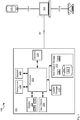
- Fig. 1 depicts a system for providing an automatically initiated outgoing communication as an incoming communication, according to non-limiting implementations.
- Fig. 2 depicts a template for providing an indication of an incoming communication in the system of Fig. 1 , according to non-limiting implementations.
- Fig. 3 depicts a method for providing an automatically initiated outgoing communication as an incoming communication, according to non-limiting implementations.
- Fig. 4 depicts the system of Fig. 1 with an outgoing communication automatically initiated, according to non-limiting implementations.
- Fig. 4 depicts the system of Fig. 1 with the template of Fig. 2 populated using meeting data, according to non-limiting implementations.
- Fig. 6 depicts an indication of an outgoing communication provided as an incoming communication, according to non-limiting implementations.
- Fig. 1 depicts a system 100 for automatically providing an automatically initiated outgoing communication as an incoming communication, and according to non-limiting implementations.
- System 100 comprises a communication device 101 enabled to initiate outgoing communications to a remote communication device 103 via a link 106.
- Communication device 101 and communication device 103 will also be respectfully referred to hereafter as device 101 and device 103. This convention will be used elsewhere in the present specification.
- Device 103 is further enabled to receive requests for communications from other communication devices 105-1, 105-2 via links 108-1, 108-2, which will also be referred to hereafter generically as a link 108, and collectively as links 108. This convention will also be used elsewhere in the present specification.
- device 103 can comprise a conference call server enabled to receive communications from one or more of devices 101, 105 in a conference call.
- communications can comprise telephone calls, voice calls, mobile calls, VoIP (voice over internet protocol) calls, PSTN (public switched telephone network) and the like.
- device 101 is generally enabled to: automatically initiate an outgoing communication at a scheduled time; and, after the outgoing communication is initiated, providing an indication of the outgoing communication at device 101 as an incoming communication at the device 101.
- system 100 can comprise any suitable number of communication devices, including hundreds to thousands to millions of devices. Indeed, system 100 can comprise any number of devices enabled to participate in a conference call at device 103.
- system 100 can comprise any suitable number of conference call servers.
- Device 101 can be any type of electronic device that can be used in a self-contained manner to interact with a communications network via link 106. It is hence appreciated that device 101 comprises any suitable communication device for communicating with device 103 and/or devices 105. Device 101 includes, but is not limited to, any suitable combination of computing devices, personal computers, laptop computers, portable electronic devices, mobile computing device, portable computing devices, tablet computing devices, laptop computing devices, desktop phones, telephones, PDAs (personal digital assistants), cellphones, smartphones and the like. Other suitable communication devices are within the scope of present implementations.
- Each of links 106, 108 comprises any suitable link, including any suitable combination of wired and/or wireless links, wired and/or wireless devices and/or wired and/or wireless networks, including but not limited to any suitable combination of USB (universal serial bus) cables, serial cables, wireless links, cell-phone links, cellular network links (including but not limited to 2G, 2,5G, 3G, 4G+, and the like) wireless data, Bluetooth links, NFC (near field communication) links, WiFi links, WiMax links, packet based links, the Internet, analog networks, the PSTN (public switched telephone network), access points, and the like, and/or a combination.
- USB universal serial bus
- serial cables serial cables
- wireless links cell-phone links
- cellular network links including but not limited to 2G, 2,5G, 3G, 4G+, and the like
- Bluetooth links including but not limited to 2G, 2,5G, 3G, 4G+, and the like
- NFC near field communication
- WiFi links Wireless Fidelity
- WiMax packet
- Fig. 1 further depicts a schematic diagram of device 101 according to non-limiting implementations. It should be emphasized that the structure of device 101 in Fig. 1 is purely exemplary, and contemplates a device that can be used for both wireless voice (e.g. telephony) and wireless data communications (e.g. email, web browsing, text, and the like).
- Device 101 comprises at least one input device 200 generally enabled to receive input data, and can comprise any suitable combination of input devices, including but not limited to a keyboard, a keypad, a pointing device, a mouse, a track wheel, a trackball, a touchpad, a touch screen and the like. Other suitable input devices are within the scope of present implementations.
- processor 208 which can be implemented as a plurality of processors, including but not limited to one or more central processing units (CPUs)).
- Processor 208 is configured to communicate with a non-volatile storage unit 212 (e.g. Erasable Electronic Programmable Read Only Memory (“EEPROM”), Flash Memory) and a volatile storage unit 216 (e.g. random access memory (“RAM”).
- EEPROM Erasable Electronic Programmable Read Only Memory
- RAM random access memory
- Programming instructions that implement the functional teachings of device 101 as described herein are typically maintained, persistently, in non-volatile storage unit 212 and used by processor 208 which makes appropriate utilization of volatile storage 216 during the execution of such programming instructions.
- non-volatile storage unit 212 and volatile storage 216 are examples of computer readable media that can store programming instructions executable on processor 208. Furthermore, non-volatile storage unit 212 and volatile storage 216 are also examples of memory units and/or memory modules.
- Processor 208 in turn can also be configured to communicate with a display 224, a microphone 226 and a speaker 229.
- Display 224 comprises any suitable one of or combination of CRT (cathode ray tube) and/or flat panel displays (e.g. LCD (liquid crystal display), plasma, OLED (organic light emitting diode), capacitive or resistive touchscreens, and the like). It is generally appreciated that display 224 comprises circuitry 230 that can be controlled, for example by processor 208, to render a representation 232 of data at display 224, for example an indication of an outgoing communication as explained in further detail below with regard to Fig. 6 .
- Microphone 226 comprises any suitable microphone for emitting sound data, which can be transmitted to device 101.
- Speaker 229 comprises any suitable speaker for providing sound data at device 101. It is appreciated that microphone 226 and speaker 229 can be used in combination at device 101 to conduct communications comprising a voice call, for example with one or more of devices 103, 105.
- input device 200 and display 224 are external to device 101, with processor 208 in communication with each of input device 200 and display 224 via a suitable connection and/or link.
- processor 208 in communication with each of input device 200 and display 224 via a suitable connection and/or link.
- microphone 226 and speaker 229 can be external to device 101, for example integrated into a headset that can be connected to device 101.
- Processor 208 also connects to a network communication interface 228, referred to hereafter as interface 228, which can be implemented as one or more radios configured to communicate over link 106.
- interface 2228 is configured to correspond with the network architecture that is used to implement link 106.
- a plurality of links with different protocols can be employed and thus interface 228 can comprise a plurality of interfaces to support each link.
- device 101 can further comprise at least one optional notification device, such as a light, an LED (light emitting diode), a vibrational motor and the like, for providing notifications of incoming communications, such as phone calls, text messages, emails and the like, either alone or in combination with each other and/or display 224 and/or speaker 229. Otherwise, notifications of incoming communications are provided via display 224, speaker 229 and/or a combination.
- a notification device such as a light, an LED (light emitting diode), a vibrational motor and the like, for providing notifications of incoming communications, such as phone calls, text messages, emails and the like, either alone or in combination with each other and/or display 224 and/or speaker 229. Otherwise, notifications of incoming communications are provided via display 224, speaker 229 and/or a combination.
- non-volatile storage 212 stores an application 250 for managing communications.
- processor 208 processes application 250, processor 208 is enabled to: automatically initiate an outgoing communication at a scheduled time, for example a voice call to device 103; and, after the outgoing communication is initiated, providing an indication of the communication at device 101 as an incoming communication at the device 101.
- non-volatile storage 212 further stores a calendar database 252 that stores meeting event data 254 comprising data associated with at least one scheduled event.
- meeting event data 254 can comprise the contents of Table 1: Table 1 Subject Patent Review Committee Meeting Date February 1, 2012 Start Time 10:00am End Time 11:00am Dial In Number 204-555-1212 Log-In Code 3459345
- Table 1 comprises data associated with a meeting (i.e. a conference call) having a subject of "Patent Review Committee Meeting” scheduled on February 1, 2012, starting at 10:00am and ending at 11:00am, that is to be held via a conferencing server with dial-in number phone number "204-555-1212", and with a participant code/log-in code of 3459345. While Table 1 is arranged in rows and columns, the format of Table 1 and/or meeting event data 254 is appreciated to be generally non-limiting.
- Table 1 includes rows and corresponding fields for a "Subject”, a “Date”, a “Start Time”, an “End Time”, a "Dial In Number” and a “Log-In Code”, the actual numbers of rows, columns, fields and format thereof, is appreciated to be non-limiting and Table 1 can comprise more rows/fields or fewer rows/fields.
- the log-in code comprises log-in data for joining an associated conference call, the log-in data to be provided to a conference server once the conference server answers a call to the conference call server.
- the log-in data is requested, for example by providing an indication to enter the log-in data (e.g. an audible indication such as "Please enter log-in data").
- Log-in data is then entered at device 101 and conveyed to the conference call server, for example via DTMF (dial-tone multi-frequency) signalling and the like.
- non-volatile storage can store at least one template 255 for providing an indication of an incoming communication, for rendering at display 224 when an in-coming communication is received.
- template 255 depicts a non limiting example of template 255 which can be specifically associated with telephone calls, including but not limited to mobile calls, voice calls, VoIP calls, PSTN based calls, and the like.
- template 255 comprises text 279 indicative that an "Incoming Call" is being received, a field 280 for providing a picture associated with an incoming call, a field 282 for providing Caller ID (identification) associated with an incoming call, and an field 284 for providing an identifier associated with an incoming call, such as an associated telephone number and the like.
- circuitry 230 is controlled at display 224 to render representation 232 of template 255, with however fields 280, 282, 284 populated with data associated with the incoming telephone call.
- field 282 is populated with the caller ID
- field 284 is populated with the associated telephone number, each of which is received as metadata with the incoming telephone call.
- Field 280 can be populated either when image data is received with the incoming telephone call and/or when image data associated with an identifier of the incoming call (e.g. the caller ID and/or the telephone number) is stored at non-volatile storage 212; otherwise field 280 can be left blank or populated with given generic image data, such as an outline of human being, and the like.
- Such generic image data can be stored at non-volatile storage 212 and/or field 280 can comprise such generic image data, which would be substituted for image data associated with the telephone call when present.
- non-volatile storage 212 can store any suitable number of similar templates for providing different types of incoming communications. For example, templates for incoming text messages, SMS (short message service) messages, MMS (multimedia message service) message, e-mail messages and the like can be provided.
- SMS short message service
- MMS multimedia message service
- Devices 105 can be similar to or different from device 101 and each of devices, 105 can include, but is not limited to, any suitable combination of computing devices, personal computers, laptop computers, portable electronic devices, mobile computing device, portable computing devices, tablet computing devices, laptop computing devices, PDAs (personal digital assistants), cellphones, smartphones and the like. Other suitable communication devices are within the scope of present implementations. Further, while two devices 105 are depicted in Fig. 1 , it is appreciated that system 100 can comprise any suitable number of communication devices. Devices 105 can comprise a processor, a communication interface, volatile and non-volatile storage, an input device, a display device, a microphone, and a speaker, similar to device 101.
- Device 103 is appreciated to also comprise a processor, non-volatile storage, volatile storage, and a communication interface, however in depicted implementations device 103 comprises a server based on any well-known server environment including a module that houses one or more central processing units, volatile memory (e.g. random access memory), persistent memory (e.g. hard disk devices) and network interfaces to allow device 103 to communicate over links 106, 108.
- volatile memory e.g. random access memory
- persistent memory e.g. hard disk devices
- network interfaces to allow device 103 to communicate over links 106, 108.
- device 103 can be a Sun Fire V480 running a UNIX operating system, from Sun Microsystems, Inc. of Palo Alto Calif., and having four central processing units each operating at about nine-hundred megahertz and having about sixteen gigabytes of random access memory.
- device 103 can comprise any suitable number of servers that can perform different functionality of server implementations described herein.
- Fig. 3 depicts a method 300 for providing an automatically initiated outgoing communication as an incoming communication, according to non-limiting implementations.
- method 300 is performed using system 100.
- system 100 and/or method 300 can be varied, and need not work exactly as discussed herein in conjunction with each other, and that such variations are within the scope of present implementations.
- method 300 is implemented in system 100 by processor 208 of device 101 processing application 250. Indeed, method 300 is one way in which device 101 can be configured. It is to be emphasized, however, that method 300 need not be performed in the exact sequence as shown; and likewise various blocks may be performed in parallel rather than in sequence; hence the elements of method 300 are referred to herein as "blocks" rather than “steps”. It is also to be understood, however, that method 300 can be implemented on variations of system 100 as well.
- an outgoing communication is automatically initiated at a scheduled given time.
- processor 208 can determine that an outgoing communication is at the scheduled given time by processing calendar database 252 to determine that the outgoing communication is associated with meeting data 254 associated with the scheduled given time.
- processor 208 can determine that the outgoing communication with device 103 is scheduled at 10:00am on February 1, 2012; hence, in this example, the scheduled given time is 10:00 am on February 1, 2012.
- processor 208 initiates an outgoing communication 401 with device 103 via interface 228 by automatically "dialling" the dial-in number (e.g. with reference to Table 1, 204-555-1212) stored at meeting data 254. Dialling is appreciated to mean any suitable steps and/or transmission of data for setting up a communication with device 103, and is not meant to be limited to dialling of a telephone.
- block 301 can include: initiating outgoing communication 401; and, when a called communication device, such as device 103, responds to a request for initiating outgoing communication 401, automatically providing log-in data for joining a conference call to the called communication device.
- processor 208 can determine that meeting data 254 comprises log-in data (e.g. with reference to Table 1, Log-In Code 3459345); hence, once outgoing communication 401 is initiated, the log-in data, when present, can be provided to device 103 (e.g. by using DTMF (dial-tone multi-frequency) signalling and the like, for example to join a conference call).
- DTMF dial-tone multi-frequency
- outgoing communication 401 can be automatically initiated at one or more of the scheduled given time and within a given time period before the scheduled given time. For example, with further reference to Table 1, outgoing communication 401 can be automatically initiated at 10:00 am on February 1, 2012 and/or within a given time period before 10:00am on February 1, 2012, such as 5 minutes before the scheduled given time. However, the scheduling of outgoing communication 401 is generally considered to be non-limiting and outgoing communication 401 can be scheduled at any suitable time.
- the scheduled time can be configurable, while in other implementations the scheduled time can be automatically determined.
- application 250 can be configured to initiate communications at a scheduled given time stored at associated meeting data stored in calendar database 252.
- application 250 can be configured to initiate communications a given time period before a scheduled given time stored at associated meeting data stored in calendar database 252.
- respective scheduled given times can be configured for each set of meeting data stored at calendar database 252 associated with a telephone number and/or remote device identifier.
- the scheduled time can be automatically determined, for example via processor 208 processing associated meeting data to determine whether log-in data, and the like, are to be provided when initiating an outgoing communication and determining the scheduled time based on such.
- threshold values can be set to determine the scheduled given time: in some non-limiting implementations, when the number of characters in the log-in data is below a threshold number of characters the scheduled time can be the scheduled given time, and when the number of characters in the log-in data is at or above a threshold number of characters, the scheduled time can be at a time that is a given time period before the scheduled given time.
- the scheduled time can be the scheduled given time, and when the number of log-in codes in the log-in data is at or above a threshold number of log-in codes, the scheduled time can be at a time that is a given time period before the scheduled given time.
- processor 208 is enabled to estimate the amount of time needed to dial the log-in number and subsequently log-in to the conference call.
- processor 208 can be enabled to provide log-in data after a given time period following dialling the log-in number, and/or when prompted by the called communication device.
- block 301 executes without providing any indication at device 101 that outgoing communication 401 is being initiated: for example, no dial-out indication is rendered at display 224, no dial-out tones are provided at speaker 229, and when device 101 comprises optional notification devices, such notification devices are not activated.
- processor 208 suppresses notifications associated with out-going communications, and/or fails to initiate such notifications. Put another way, outgoing communication 401 is initiated in the background.
- outgoing communication 401 can be initiated without providing an indicator of outgoing communication 401 other than an indication rendered in an indicator area of display 224, including but not limited to an icon, a status icon, a radio-in-use icon and the like.
- the indicator area can comprise a header of representation 232 at display 224.
- At least a portion of normally provided indications outgoing communications are suppressed when outgoing communication 401 is initiated. For example, one or more of a dial-out indication and a dial-tone is suppressed. In some of these implementations, at least a portion of normally provided indications of outgoing communications are suppressed by muting speaker 229. Further, at least a portion of normally provided indications of outgoing communications can be suppressed by preventing rendering of an identifier of a remote communication device associated with outgoing communication 401: for example, when outgoing communication 401 is intended for device 103, an identifier of device 103, for example a telephone number, is not rendered at display 224.
- an indication of outgoing communication 401 is provided at device 101, such that outgoing communication 401 is provided as an incoming communication at device 401.
- a notification device at device 101 is activated to indicate that an incoming call can be accepted or declined: for example device 101 rings, vibrates, a light flashes, and/or a notification is rendered at display 224.
- template 255 can be populated and rendered at display 224.
- FIG. 5 depicts processor 208 processing meeting data 254 to populate fields 282, 284 of template 255, and a representation of such is rendered in representation 232 at display 224.
- representation 232 is depicted in Fig. 6 . From Fig. 6 it is appreciated that each of elements 679, 680, 682, 684 of representation 232 corresponds to fields 279, 280, 282, 284 of template 255.
- element 679 comprises text "Incoming Call" similar to field 279.
- Element 680 corresponds to field 280, however populated with generic image data as no incoming communication was actually received; rather an outgoing communication was initiated; in implementations where image data is stored at non-volatile storage 212 in association with, for example, an identifier of device 103, processor 208 can populate filed 280 with such image data.
- Element 682 corresponds to field 282, however populated with "Subject” data from Table 1.
- element 684 corresponds to field 284, however populated with the "Dial-In Number” data from Table 1.
- "Subject" data of Table 1 is rendered as a caller ID in representation 232 and "Dial-In Number” of Table 1 is rendered as an identifier of device 103.
- an indication (e.g. representation 232) of outgoing communication 401 is provided as if outgoing communication 401 were actually an incoming communication.
- representation 232 further comprises virtual buttons 690, 692 for respectfully accepting outgoing communication 401 or declining outgoing communication 40, as if outgoing communication 401 were an incoming call; each buttons 690, 692 can be actuated via input device 200.
- device 101 provides representation 232 as an indication of outgoing communication 401, but as if outgoing communication 401 were actually an incoming communication and further uses the same template 255 used to provide indications of incoming communications.
- Buttons 690, 692 are appreciated to be only one implementation for accepting or declining outgoing communication 401, and that any suitable process and/or hardware for accepting or declining outgoing communication 401 is within the scope of present implementations.
- the indication of outgoing communication 401 is provided as one or more of a caller ID, an identifier of outgoing communication 401, an identifier of a conference call associated with outgoing communication 401, and an identifier of meeting data associated with the outgoing communication.
- identifiers include, but are not limited to, a subject stored in associated meeting data 254, start and end times associated with meeting data 254, an identifier of device 103, such as a telephone number, log-in data associated with meeting data 254, some or all of which can be provided in fields 282, 284 of template 255, and the like.
- speaker 229 is muted at block 301
- speaker is unmuted.
- method 300 can further comprise, when connecting outgoing communication 401 is unsuccessful, automatically reattempting automatically initiating the outgoing communication 401 after a given time period.
- block 301 can be re-executed after a suitable given time period (e.g. a few minutes). Block 301 can repeat until communication 401 is successful. In other words, device 101 reattempts to connect with device 101 if previous attempts to connect with device 103 are unsuccessful.
- method 300 can end after a given number of executions of block 301 and/or after a given time period.
- no response to an indication of outgoing communication 401 can occur.
- a missed call log (not depicted) stored at non-volatile storage 212 can be provided which stores a missed call entry associated with communication 401.
- a missed call entry could include, but is not limited to, data provided at one or more of elements 682, 684, along with additional context data indicating a context of associated communication 401.
- the call log entry could comprise one or more icons indicating that the missed communication 401 was an outgoing call, a conference call or the like.
- the icon when communication 401 is associated with a reminder, such as a birthday reminder, the icon could comprise a picture associated with the reminder: when a birthday reminder, the icon could comprise a birthday cake, etc.
- context information associated with communication 401 in the missed call entry could enable missed call log to processed and/or accessed in the context of communication 401.
- context information could indicate to a user of device 101 the nature of communication 401 when the missed call entry is rendered at display 224 along with the context information.
- the missed call entry can comprise additional options based on context when rendered at display 224.
- options related to conference calls can be provided as virtual buttons, including but not limited to "Join Conference”, “Join Conference Silently”, “Join Conference as Moderator", and the like; when a virtual buttons are actuated, the indicated action be taken at device 101.
- the indication (e.g. representation 232) of outgoing communication 401 can be provided when one of a called communication device (e.g. device 103) answers outgoing communication 401 (e.g. the call to device 103 is answered), and when outgoing communication 401 is logged into an associated conference call.
- processor 208 can be enabled to render the indication (e.g. representations 232) of outgoing communication when device 103 answers outgoing communication 403, such that when accept button 690 is actuated, device 103 is connected and, other then entering the log-in data (which can be done either manually or automatically), device 103 is connected to device 101, and a user of device 101 can start speaking in the conference call.
- the indication (e.g. representation 232) of outgoing communication 401 can be provided when outgoing communication 401 is logged into an associated conference call such that upon actuation of button 690, a user of device 101 can start speaking in the conference call.
- providing the indication of outgoing communication 401 can be provided before a called communication device (e.g. device 103) answers outgoing communication 401.
- a called communication device e.g. device 103
- button 690 when button 690 is actuated, "ringing" or any other suitable notification is played at speaker 229 to indicate that the called communication device (e.g. device 103) has not yet accepted outgoing communication 401.
- the indication when the indication is provided before one of a called communication device (e.g. device 103) answers the outgoing communication 401 and the outgoing communication 401 is logged into an associated conference call, the outgoing communication 401 can be muted until, for example the outgoing communication 401 is answered and/or the conference call is entered.
- method 300 can be implemented at device 101 to provide an automatically initiated outgoing communication to any suitable communication device as an incoming communication, for example one or more of devices 105. Further, method 300 can be implemented sequentially to set up conference calls. For example, when meeting data 254 comprises more than one phone number, each number can be dialled in any suitable sequence, in the background (i.e. block 301 executes more than once, and/or one time for each phone number), and block 303 executes at a suitable time, for example once each phone number is connected.
- method 300 is not limited to phone calls. Rather, any outgoing communication can be provided at device 101 as an incoming communication.
- device 101 can automatically initiate a text message session and provide an outgoing text message as an incoming text message.
- device 101 can automatically initiate a video call and provide an outgoing video call as an incoming video call.
- the functionality of device 101 can be implemented using pre-programmed hardware or firmware elements (e.g., application specific integrated circuits (ASICs), electrically erasable programmable read-only memories (EEPROMs), etc.), or other related components.
- the functionality of devices 101 can be achieved using a computing apparatus that has access to a code memory (not shown) which stores computer-readable program code for operation of the computing apparatus.
- the computer-readable program code could be stored on a computer readable storage medium which is fixed, tangible and readable directly by these components, (e.g., removable diskette, CD-ROM, ROM, fixed disk, USB drive).
- the computer-readable program can be stored as a computer program product comprising a computer usable medium.
- a persistent storage device can comprise the computer readable program code.
- the computer-readable program code and/or computer usable medium can comprise a non-transitory computer-readable program code and/or non-transitory computer usable medium.
- the computer-readable program code could be stored remotely but transmittable to these components via a modem or other interface device connected to a network (including, without limitation, the Internet) over a transmission medium.
- the transmission medium can be either a non-mobile medium (e.g., optical and/or digital and/or analog communications lines) or a mobile medium (e.g., microwave, infrared, free-space optical or other transmission schemes) or a combination thereof.
Landscapes
- Engineering & Computer Science (AREA)
- Computer Vision & Pattern Recognition (AREA)
- Multimedia (AREA)
- Signal Processing (AREA)
- Telephonic Communication Services (AREA)
- Telephone Function (AREA)
Abstract
Description
- The specification relates generally to communication devices, and specifically to a communication device for providing an automatically initiated outgoing communication as an incoming communication.
- The evolution of computers is currently quite active in the mobile device environment. It is now well-known to including calendaring, contacts, and messaging functions in mobile devices. More recently, there has been a veritable explosion of the number and type of applications that are configured to the unique form factors and computing environments of mobile devices.
- An aspect of the specification provides a communication device comprising: a processor and a communication interface, the processor enabled to: automatically initiate an outgoing communication at a scheduled given time via the communication interface; and, after the outgoing communication is initiated, provide an indication of the outgoing communication, such that the outgoing communication is provided as an incoming communication.
- The outgoing communication can be initiated without providing an indicator of the outgoing communication. The outgoing communication can be initiated without providing an indicator of the outgoing communication other than an indicator of the outgoing communication rendered in an indicator area of a display of the communication device. The indicator can comprise one or more of an icon and a radio-in-use icon. The indicator area can comprise a header of at the display.
- When the outgoing communication is initiated, at least a portion of normally provided indications associated with outgoing communications can be suppressed. One or more of a dial-out indication and a dial-tone can be suppressed. At least a portion of normally provided indications of outgoing communications can be suppressed by muting a speaker at the communication device. At least a portion of normally provided indications of outgoing communications can be suppressed by preventing rendering of an identifier of a remote communication device associated with the outgoing communication.
- The indication of the outgoing communication can be provided as one or more of a caller ID (identification), an identifier of the outgoing communication, an identifier of a conference call associated with the outgoing communication, and an identifier of meeting data associated with the outgoing communication.
- The indication can comprise an incoming communication template with fields populated with outgoing communication data.
- The processor can be further enabled to determine that the outgoing communication is scheduled by processing a calendar database to determine that the outgoing communication is associated with meeting data associated with the scheduled given time.
- The processor can be further enabled to automatically initiate the outgoing communication at one or more of the scheduled given time and within a given time period before the scheduled given time.
- The processor can be further enabled to automatically initiate the outgoing communication by: initiating the outgoing communication; and, when a called communication device responds to a request for initiating the outgoing communication, automatically providing log-in data for joining a conference call to the called communication device.
- The processor can be further enabled to, when connecting the outgoing communication is unsuccessful, automatically reattempt to automatically initiate the outgoing communication after a given time period.
- The processor can be further enabled to provide the indication of the outgoing communication when one of a called communication device answers the outgoing communication, and when the outgoing communication is logged into an associated conference call.
- The processor can be further enabled to, when the indication is provided before one of a called communication device answers the outgoing communication and the outgoing communication is logged into an associated conference call, mute the outgoing communication.
- A further aspect of the specification provides a method comprising: automatically initiating, at a processor of a communication device, an outgoing communication at a scheduled given time via a communication interface of the communication device; and, after the outgoing communication is initiated, providing an indication of the outgoing communication at the communication device, such that the outgoing communication is provided as an incoming communication at the communication device.
- The outgoing communication can be initiated without providing an indicator of the outgoing communication. The outgoing communication can be initiated without providing an indicator of the outgoing communication other than an indicator of the outgoing communication rendered in an indicator area of a display of the communication device. The indicator can comprise one or more of an icon and a radio-in-use icon. The indicator area can comprise a header of at the display.
- When the outgoing communication is initiated, at least a portion of normally provided indications associated with outgoing communications can be suppressed. One or more of a dial-out indication and a dial-tone can be suppressed. At least a portion of normally provided indications of outgoing communications can be suppressed by muting a speaker at the communication device. At least a portion of normally provided indications of outgoing communications can be suppressed by preventing rendering of an identifier of a remote communication device associated with the outgoing communication.
- The indication of the outgoing communication can be provided as one or more of a caller ID (identification), an identifier of the outgoing communication, an identifier of a conference call associated with the outgoing communication, and an identifier of meeting data associated with the outgoing communication.
- The indication can comprise an incoming communication template with fields populated with outgoing communication data.
- The method can further comprise determining that the outgoing communication is scheduled can by processing a calendar database to determine that the outgoing communication is associated with meeting data associated with the scheduled given time.
- The outgoing communication can be automatically initiated at one or more of the scheduled given time and within a given time period before the scheduled given time.
- Automatically initiating the outgoing communication can comprise: initiating the outgoing communication; and, when a called communication device responds to a request for initiating the outgoing communication, automatically providing log-in data for joining a conference call to the called communication device.
- The method can further comprise, when connecting the outgoing communication is unsuccessful, automatically reattempting automatically initiating the outgoing communication after a given time period.
- The indication of the outgoing communication can be provided when one of a called communication device answers the outgoing communication, and when the outgoing communication is logged into an associated conference call.
- When the indication is provided before one of a called communication device answers the outgoing communication and the outgoing communication is logged into an associated conference call, the outgoing communication can be muted.
- Yet another aspect of the specification provides a computer program product, comprising a computer usable medium having a computer readable program code adapted to be execute a method comprising: automatically initiating, at a processor of a communication device, an outgoing communication at a scheduled given time via a communication interface of the communication device; and, after the outgoing communication is initiated, providing an indication of the outgoing communication at the communication device, such that the outgoing communication is provided as an incoming communication at the communication device. The computer program product can comprise a non-transitory computer program product.
- For a better understanding of the various implementations described herein and to show more clearly how they may be carried into effect, reference will now be made, by way of example only, to the accompanying drawings in which:
-
Fig. 1 depicts a system for providing an automatically initiated outgoing communication as an incoming communication, according to non-limiting implementations. -
Fig. 2 depicts a template for providing an indication of an incoming communication in the system ofFig. 1 , according to non-limiting implementations. -
Fig. 3 depicts a method for providing an automatically initiated outgoing communication as an incoming communication, according to non-limiting implementations. -
Fig. 4 depicts the system ofFig. 1 with an outgoing communication automatically initiated, according to non-limiting implementations. -
Fig. 4 depicts the system ofFig. 1 with the template ofFig. 2 populated using meeting data, according to non-limiting implementations. -
Fig. 6 depicts an indication of an outgoing communication provided as an incoming communication, according to non-limiting implementations. -
Fig. 1 depicts asystem 100 for automatically providing an automatically initiated outgoing communication as an incoming communication, and according to non-limiting implementations.System 100 comprises acommunication device 101 enabled to initiate outgoing communications to aremote communication device 103 via alink 106.Communication device 101 andcommunication device 103 will also be respectfully referred to hereafter asdevice 101 anddevice 103. This convention will be used elsewhere in the present specification.Device 103 is further enabled to receive requests for communications from other communication devices 105-1, 105-2 via links 108-1, 108-2, which will also be referred to hereafter generically as a link 108, and collectively as links 108. This convention will also be used elsewhere in the present specification. For example,device 103 can comprise a conference call server enabled to receive communications from one or more ofdevices 101, 105 in a conference call. In such implementations, communications can comprise telephone calls, voice calls, mobile calls, VoIP (voice over internet protocol) calls, PSTN (public switched telephone network) and the like. - As will be described below,
device 101 is generally enabled to: automatically initiate an outgoing communication at a scheduled time; and, after the outgoing communication is initiated, providing an indication of the outgoing communication atdevice 101 as an incoming communication at thedevice 101. - It is further more appreciated that while only three
devices 101, 105 are depicted inFig. 1 ,system 100 can comprise any suitable number of communication devices, including hundreds to thousands to millions of devices. Indeed,system 100 can comprise any number of devices enabled to participate in a conference call atdevice 103. - Furthermore, while only one
device 103 is depicted inFig. 1 ,system 100 can comprise any suitable number of conference call servers. -
Device 101 can be any type of electronic device that can be used in a self-contained manner to interact with a communications network vialink 106. It is hence appreciated thatdevice 101 comprises any suitable communication device for communicating withdevice 103 and/or devices 105.Device 101 includes, but is not limited to, any suitable combination of computing devices, personal computers, laptop computers, portable electronic devices, mobile computing device, portable computing devices, tablet computing devices, laptop computing devices, desktop phones, telephones, PDAs (personal digital assistants), cellphones, smartphones and the like. Other suitable communication devices are within the scope of present implementations. - Each of
links 106, 108 comprises any suitable link, including any suitable combination of wired and/or wireless links, wired and/or wireless devices and/or wired and/or wireless networks, including but not limited to any suitable combination of USB (universal serial bus) cables, serial cables, wireless links, cell-phone links, cellular network links (including but not limited to 2G, 2,5G, 3G, 4G+, and the like) wireless data, Bluetooth links, NFC (near field communication) links, WiFi links, WiMax links, packet based links, the Internet, analog networks, the PSTN (public switched telephone network), access points, and the like, and/or a combination. - It is appreciated that
Fig. 1 further depicts a schematic diagram ofdevice 101 according to non-limiting implementations. It should be emphasized that the structure ofdevice 101 inFig. 1 is purely exemplary, and contemplates a device that can be used for both wireless voice (e.g. telephony) and wireless data communications (e.g. email, web browsing, text, and the like).Device 101 comprises at least oneinput device 200 generally enabled to receive input data, and can comprise any suitable combination of input devices, including but not limited to a keyboard, a keypad, a pointing device, a mouse, a track wheel, a trackball, a touchpad, a touch screen and the like. Other suitable input devices are within the scope of present implementations. - Input from
input device 200 is received at processor 208 (which can be implemented as a plurality of processors, including but not limited to one or more central processing units (CPUs)).Processor 208 is configured to communicate with a non-volatile storage unit 212 (e.g. Erasable Electronic Programmable Read Only Memory ("EEPROM"), Flash Memory) and a volatile storage unit 216 (e.g. random access memory ("RAM")). Programming instructions that implement the functional teachings ofdevice 101 as described herein are typically maintained, persistently, innon-volatile storage unit 212 and used byprocessor 208 which makes appropriate utilization ofvolatile storage 216 during the execution of such programming instructions. Those skilled in the art will now recognize thatnon-volatile storage unit 212 andvolatile storage 216 are examples of computer readable media that can store programming instructions executable onprocessor 208. Furthermore,non-volatile storage unit 212 andvolatile storage 216 are also examples of memory units and/or memory modules. -
Processor 208 in turn can also be configured to communicate with adisplay 224, amicrophone 226 and aspeaker 229.Display 224 comprises any suitable one of or combination of CRT (cathode ray tube) and/or flat panel displays (e.g. LCD (liquid crystal display), plasma, OLED (organic light emitting diode), capacitive or resistive touchscreens, and the like). It is generally appreciated thatdisplay 224 comprisescircuitry 230 that can be controlled, for example byprocessor 208, to render arepresentation 232 of data atdisplay 224, for example an indication of an outgoing communication as explained in further detail below with regard toFig. 6 . -
Microphone 226 comprises any suitable microphone for emitting sound data, which can be transmitted todevice 101.Speaker 229 comprises any suitable speaker for providing sound data atdevice 101. It is appreciated thatmicrophone 226 andspeaker 229 can be used in combination atdevice 101 to conduct communications comprising a voice call, for example with one or more ofdevices 103, 105. - In some implementations,
input device 200 anddisplay 224 are external todevice 101, withprocessor 208 in communication with each ofinput device 200 anddisplay 224 via a suitable connection and/or link. Similarly,microphone 226 andspeaker 229 can be external todevice 101, for example integrated into a headset that can be connected todevice 101. -
Processor 208 also connects to anetwork communication interface 228, referred to hereafter asinterface 228, which can be implemented as one or more radios configured to communicate overlink 106. In general, it will be understood thatinterface 228 is configured to correspond with the network architecture that is used to implementlink 106. In other implementations a plurality of links with different protocols can be employed and thus interface 228 can comprise a plurality of interfaces to support each link. - While not depicted, in some implementations,
device 101 can further comprise at least one optional notification device, such as a light, an LED (light emitting diode), a vibrational motor and the like, for providing notifications of incoming communications, such as phone calls, text messages, emails and the like, either alone or in combination with each other and/ordisplay 224 and/orspeaker 229. Otherwise, notifications of incoming communications are provided viadisplay 224,speaker 229 and/or a combination. - In particular, it is appreciated that
non-volatile storage 212 stores anapplication 250 for managing communications. Whenprocessor 208processes application 250,processor 208 is enabled to: automatically initiate an outgoing communication at a scheduled time, for example a voice call todevice 103; and, after the outgoing communication is initiated, providing an indication of the communication atdevice 101 as an incoming communication at thedevice 101. - In some implementations,
non-volatile storage 212 further stores acalendar database 252 that stores meetingevent data 254 comprising data associated with at least one scheduled event. For examplemeeting event data 254 can comprise the contents of Table 1:Table 1 Subject Patent Review Committee Meeting Date February 1, 2012 Start Time 10:00am End Time 11:00am Dial In Number 204-555-1212 Log-In Code 3459345 - Table 1 comprises data associated with a meeting (i.e. a conference call) having a subject of "Patent Review Committee Meeting" scheduled on February 1, 2012, starting at 10:00am and ending at 11:00am, that is to be held via a conferencing server with dial-in number phone number "204-555-1212", and with a participant code/log-in code of 3459345. While Table 1 is arranged in rows and columns, the format of Table 1 and/or meeting
event data 254 is appreciated to be generally non-limiting. For example, while Table 1 includes rows and corresponding fields for a "Subject", a "Date", a "Start Time", an "End Time", a "Dial In Number" and a "Log-In Code", the actual numbers of rows, columns, fields and format thereof, is appreciated to be non-limiting and Table 1 can comprise more rows/fields or fewer rows/fields. - It is further appreciated that the log-in code comprises log-in data for joining an associated conference call, the log-in data to be provided to a conference server once the conference server answers a call to the conference call server. In practice, once the conference server answers the call, the log-in data is requested, for example by providing an indication to enter the log-in data (e.g. an audible indication such as "Please enter log-in data"). Log-in data is then entered at
device 101 and conveyed to the conference call server, for example via DTMF (dial-tone multi-frequency) signalling and the like. - It is further appreciated that while only one log-in code is depicted in Table 1, in other implementations, any suitable number of log-in codes can be provided, for example when an associated conference call requires more than one log-in code.
- It is further appreciated that non-volatile storage can store at least one
template 255 for providing an indication of an incoming communication, for rendering atdisplay 224 when an in-coming communication is received. For example, attention is directed toFig. 2 which depicts a non limiting example oftemplate 255 which can be specifically associated with telephone calls, including but not limited to mobile calls, voice calls, VoIP calls, PSTN based calls, and the like. As depicted,template 255 comprisestext 279 indicative that an "Incoming Call" is being received, afield 280 for providing a picture associated with an incoming call, afield 282 for providing Caller ID (identification) associated with an incoming call, and anfield 284 for providing an identifier associated with an incoming call, such as an associated telephone number and the like. Hence, when an incoming telephone call is received,circuitry 230 is controlled atdisplay 224 to renderrepresentation 232 oftemplate 255, with however fields 280, 282, 284 populated with data associated with the incoming telephone call. For example,field 282 is populated with the caller ID, andfield 284 is populated with the associated telephone number, each of which is received as metadata with the incoming telephone call.Field 280 can be populated either when image data is received with the incoming telephone call and/or when image data associated with an identifier of the incoming call (e.g. the caller ID and/or the telephone number) is stored atnon-volatile storage 212; otherwise field 280 can be left blank or populated with given generic image data, such as an outline of human being, and the like. Such generic image data can be stored atnon-volatile storage 212 and/orfield 280 can comprise such generic image data, which would be substituted for image data associated with the telephone call when present. - While
template 255 has been described with reference to a telephone call, it is appreciated thatnon-volatile storage 212 can store any suitable number of similar templates for providing different types of incoming communications. For example, templates for incoming text messages, SMS (short message service) messages, MMS (multimedia message service) message, e-mail messages and the like can be provided. - In any event, it should be understood that in general a wide variety of configurations for
device 101 are contemplated. - Devices 105 can be similar to or different from
device 101 and each of devices, 105 can include, but is not limited to, any suitable combination of computing devices, personal computers, laptop computers, portable electronic devices, mobile computing device, portable computing devices, tablet computing devices, laptop computing devices, PDAs (personal digital assistants), cellphones, smartphones and the like. Other suitable communication devices are within the scope of present implementations. Further, while two devices 105 are depicted inFig. 1 , it is appreciated thatsystem 100 can comprise any suitable number of communication devices. Devices 105 can comprise a processor, a communication interface, volatile and non-volatile storage, an input device, a display device, a microphone, and a speaker, similar todevice 101. -
Device 103 is appreciated to also comprise a processor, non-volatile storage, volatile storage, and a communication interface, however in depictedimplementations device 103 comprises a server based on any well-known server environment including a module that houses one or more central processing units, volatile memory (e.g. random access memory), persistent memory (e.g. hard disk devices) and network interfaces to allowdevice 103 to communicate overlinks 106, 108. For example,device 103 can be a Sun Fire V480 running a UNIX operating system, from Sun Microsystems, Inc. of Palo Alto Calif., and having four central processing units each operating at about nine-hundred megahertz and having about sixteen gigabytes of random access memory. However, it is to be emphasized that this particular server is merely exemplary, and a vast array of other types of computing environments fordevice 103 are contemplated. It is further more appreciated thatdevice 103 can comprise any suitable number of servers that can perform different functionality of server implementations described herein. - Attention is now directed to
Fig. 3 which depicts amethod 300 for providing an automatically initiated outgoing communication as an incoming communication, according to non-limiting implementations. In order to assist in the explanation ofmethod 300, it will be assumed thatmethod 300 is performed usingsystem 100. Furthermore, the following discussion ofmethod 300 will lead to a further understanding ofsystem 100 and its various components. However, it is to be understood thatsystem 100 and/ormethod 300 can be varied, and need not work exactly as discussed herein in conjunction with each other, and that such variations are within the scope of present implementations. - It is appreciated that, in some implementations,
method 300 is implemented insystem 100 byprocessor 208 ofdevice 101processing application 250. Indeed,method 300 is one way in whichdevice 101 can be configured. It is to be emphasized, however, thatmethod 300 need not be performed in the exact sequence as shown; and likewise various blocks may be performed in parallel rather than in sequence; hence the elements ofmethod 300 are referred to herein as "blocks" rather than "steps". It is also to be understood, however, thatmethod 300 can be implemented on variations ofsystem 100 as well. - Furthermore,
method 300 will be described with reference toFigs. 4 and5 , each of which are substantially similar toFig. 1 , with like elements having like numbers. - At
block 301, an outgoing communication is automatically initiated at a scheduled given time. For example,processor 208 can determine that an outgoing communication is at the scheduled given time by processingcalendar database 252 to determine that the outgoing communication is associated with meetingdata 254 associated with the scheduled given time. With reference to Table 1 above, in a non-limiting example,processor 208 can determine that the outgoing communication withdevice 103 is scheduled at 10:00am on February 1, 2012; hence, in this example, the scheduled given time is 10:00 am on February 1, 2012. With reference toFig. 4 ,processor 208 initiates anoutgoing communication 401 withdevice 103 viainterface 228 by automatically "dialling" the dial-in number (e.g. with reference to Table 1, 204-555-1212) stored at meetingdata 254. Dialling is appreciated to mean any suitable steps and/or transmission of data for setting up a communication withdevice 103, and is not meant to be limited to dialling of a telephone. - It is further appreciated, that
block 301 can include: initiatingoutgoing communication 401; and, when a called communication device, such asdevice 103, responds to a request for initiatingoutgoing communication 401, automatically providing log-in data for joining a conference call to the called communication device. With reference to Table 1 above, in a non-limiting example,processor 208 can determine thatmeeting data 254 comprises log-in data (e.g. with reference to Table 1, Log-In Code 3459345); hence, onceoutgoing communication 401 is initiated, the log-in data, when present, can be provided to device 103 (e.g. by using DTMF (dial-tone multi-frequency) signalling and the like, for example to join a conference call). - Furthermore,
outgoing communication 401 can be automatically initiated at one or more of the scheduled given time and within a given time period before the scheduled given time. For example, with further reference to Table 1,outgoing communication 401 can be automatically initiated at 10:00 am on February 1, 2012 and/or within a given time period before 10:00am on February 1, 2012, such as 5 minutes before the scheduled given time. However, the scheduling ofoutgoing communication 401 is generally considered to be non-limiting andoutgoing communication 401 can be scheduled at any suitable time. - Further, in some implementations, the scheduled time can be configurable, while in other implementations the scheduled time can be automatically determined. For example,
application 250 can be configured to initiate communications at a scheduled given time stored at associated meeting data stored incalendar database 252. Alternatively,application 250 can be configured to initiate communications a given time period before a scheduled given time stored at associated meeting data stored incalendar database 252. In yet further alternatives, respective scheduled given times can be configured for each set of meeting data stored atcalendar database 252 associated with a telephone number and/or remote device identifier. - In yet further implementations, the scheduled time can be automatically determined, for example via
processor 208 processing associated meeting data to determine whether log-in data, and the like, are to be provided when initiating an outgoing communication and determining the scheduled time based on such. For example, threshold values can be set to determine the scheduled given time: in some non-limiting implementations, when the number of characters in the log-in data is below a threshold number of characters the scheduled time can be the scheduled given time, and when the number of characters in the log-in data is at or above a threshold number of characters, the scheduled time can be at a time that is a given time period before the scheduled given time. - Alternatively, when the number of log-in codes in the log-in data is below a threshold number of log-in codes, the scheduled time can be the scheduled given time, and when the number of log-in codes in the log-in data is at or above a threshold number of log-in codes, the scheduled time can be at a time that is a given time period before the scheduled given time. In other words,
processor 208 is enabled to estimate the amount of time needed to dial the log-in number and subsequently log-in to the conference call. - Further,
processor 208 can be enabled to provide log-in data after a given time period following dialling the log-in number, and/or when prompted by the called communication device. - Further, in some implementations, block 301 executes without providing any indication at
device 101 thatoutgoing communication 401 is being initiated: for example, no dial-out indication is rendered atdisplay 224, no dial-out tones are provided atspeaker 229, and whendevice 101 comprises optional notification devices, such notification devices are not activated. In other words,processor 208 suppresses notifications associated with out-going communications, and/or fails to initiate such notifications. Put another way,outgoing communication 401 is initiated in the background. - In yet further implementations,
outgoing communication 401 can be initiated without providing an indicator ofoutgoing communication 401 other than an indication rendered in an indicator area ofdisplay 224, including but not limited to an icon, a status icon, a radio-in-use icon and the like. The indicator area can comprise a header ofrepresentation 232 atdisplay 224. - In yet further implementations, at least a portion of normally provided indications outgoing communications are suppressed when
outgoing communication 401 is initiated. For example, one or more of a dial-out indication and a dial-tone is suppressed. In some of these implementations, at least a portion of normally provided indications of outgoing communications are suppressed by mutingspeaker 229. Further, at least a portion of normally provided indications of outgoing communications can be suppressed by preventing rendering of an identifier of a remote communication device associated with outgoing communication 401: for example, whenoutgoing communication 401 is intended fordevice 103, an identifier ofdevice 103, for example a telephone number, is not rendered atdisplay 224. - Rather, returning to
Fig. 3 , atblock 303 afteroutgoing communication 401 is initiated, an indication ofoutgoing communication 401 is provided atdevice 101, such thatoutgoing communication 401 is provided as an incoming communication atdevice 401. In some implementations, a notification device atdevice 101 is activated to indicate that an incoming call can be accepted or declined: forexample device 101 rings, vibrates, a light flashes, and/or a notification is rendered atdisplay 224. - Alternatively,
template 255 can be populated and rendered atdisplay 224. For example, attention is again directed toFig. 5 which depictsprocessor 208processing meeting data 254 to populatefields template 255, and a representation of such is rendered inrepresentation 232 atdisplay 224. A non-limiting example ofrepresentation 232 is depicted inFig. 6 . FromFig. 6 it is appreciated that each ofelements representation 232 corresponds tofields template 255. For example,element 679 comprises text "Incoming Call" similar tofield 279.Element 680 corresponds to field 280, however populated with generic image data as no incoming communication was actually received; rather an outgoing communication was initiated; in implementations where image data is stored atnon-volatile storage 212 in association with, for example, an identifier ofdevice 103,processor 208 can populate filed 280 with such image data. -
Element 682 corresponds to field 282, however populated with "Subject" data from Table 1. Similarly,element 684 corresponds to field 284, however populated with the "Dial-In Number" data from Table 1. Hence, "Subject" data of Table 1 is rendered as a caller ID inrepresentation 232 and "Dial-In Number" of Table 1 is rendered as an identifier ofdevice 103. In other words, an indication (e.g. representation 232) ofoutgoing communication 401 is provided as ifoutgoing communication 401 were actually an incoming communication. - To this end,
representation 232 further comprisesvirtual buttons outgoing communication 401 or declining outgoing communication 40, as ifoutgoing communication 401 were an incoming call; eachbuttons input device 200. In other words,device 101 providesrepresentation 232 as an indication ofoutgoing communication 401, but as ifoutgoing communication 401 were actually an incoming communication and further uses thesame template 255 used to provide indications of incoming communications.Buttons outgoing communication 401, and that any suitable process and/or hardware for accepting or decliningoutgoing communication 401 is within the scope of present implementations. - It is appreciated that the indication of
outgoing communication 401 is provided as one or more of a caller ID, an identifier ofoutgoing communication 401, an identifier of a conference call associated withoutgoing communication 401, and an identifier of meeting data associated with the outgoing communication. Examples of various identifiers include, but are not limited to, a subject stored in associatedmeeting data 254, start and end times associated with meetingdata 254, an identifier ofdevice 103, such as a telephone number, log-in data associated with meetingdata 254, some or all of which can be provided infields template 255, and the like. - In implementations where
speaker 229 is muted atblock 301, atblock 303 speaker is unmuted. - Various alternatives and variations of
method 300 are within the scope of present implementations. - For example,
method 300 can further comprise, when connectingoutgoing communication 401 is unsuccessful, automatically reattempting automatically initiating theoutgoing communication 401 after a given time period. For example, whenoutgoing communication 401 is not successful at connecting withdevice 103, for example becausedevice 103 is busy and the like, block 301 can be re-executed after a suitable given time period (e.g. a few minutes). Block 301 can repeat untilcommunication 401 is successful. In other words,device 101 reattempts to connect withdevice 101 if previous attempts to connect withdevice 103 are unsuccessful. In some of these implementations,method 300 can end after a given number of executions ofblock 301 and/or after a given time period. - In yet further implementations, no response to an indication of
outgoing communication 401 can occur. In other words, when representation 292 ofFig. 6 is provided atdevice 101, neither ofbuttons non-volatile storage 212 can be provided which stores a missed call entry associated withcommunication 401. For example, a missed call entry could include, but is not limited to, data provided at one or more ofelements communication 401. For example, the call log entry could comprise one or more icons indicating that the missedcommunication 401 was an outgoing call, a conference call or the like. As a further example, whencommunication 401 is associated with a reminder, such as a birthday reminder, the icon could comprise a picture associated with the reminder: when a birthday reminder, the icon could comprise a birthday cake, etc. - In any event, storing of context information associated with
communication 401 in the missed call entry could enable missed call log to processed and/or accessed in the context ofcommunication 401. At a minimum, such context information could indicate to a user ofdevice 101 the nature ofcommunication 401 when the missed call entry is rendered atdisplay 224 along with the context information. - In some of these implementations, the missed call entry can comprise additional options based on context when rendered at
display 224. For example, whencommunication 401 was missed andcommunication 401 comprised a conference call, when the associated missed call entry is rendered atdisplay 224, options related to conference calls can be provided as virtual buttons, including but not limited to "Join Conference", "Join Conference Silently", "Join Conference as Moderator", and the like; when a virtual buttons are actuated, the indicated action be taken atdevice 101. - Indeed, in yet further implementations, the indication (e.g. representation 232) of
outgoing communication 401 can be provided when one of a called communication device (e.g. device 103) answers outgoing communication 401 (e.g. the call todevice 103 is answered), and whenoutgoing communication 401 is logged into an associated conference call. For example,processor 208 can be enabled to render the indication (e.g. representations 232) of outgoing communication whendevice 103 answers outgoing communication 403, such that when acceptbutton 690 is actuated,device 103 is connected and, other then entering the log-in data (which can be done either manually or automatically),device 103 is connected todevice 101, and a user ofdevice 101 can start speaking in the conference call. Similarly, the indication (e.g. representation 232) ofoutgoing communication 401 can be provided whenoutgoing communication 401 is logged into an associated conference call such that upon actuation ofbutton 690, a user ofdevice 101 can start speaking in the conference call. - However, providing the indication of
outgoing communication 401 can be provided before a called communication device (e.g. device 103) answersoutgoing communication 401. In these implementations, whenbutton 690 is actuated, "ringing" or any other suitable notification is played atspeaker 229 to indicate that the called communication device (e.g. device 103) has not yet acceptedoutgoing communication 401. Alternatively, when the indication is provided before one of a called communication device (e.g. device 103) answers theoutgoing communication 401 and theoutgoing communication 401 is logged into an associated conference call, theoutgoing communication 401 can be muted until, for example theoutgoing communication 401 is answered and/or the conference call is entered. - While present implementations have been described with reference to dialling into a conference call at a conference call server, it is appreciated that
method 300 is not so limited. Rather,method 300 can be implemented atdevice 101 to provide an automatically initiated outgoing communication to any suitable communication device as an incoming communication, for example one or more of devices 105. Further,method 300 can be implemented sequentially to set up conference calls. For example, when meetingdata 254 comprises more than one phone number, each number can be dialled in any suitable sequence, in the background (i.e. block 301 executes more than once, and/or one time for each phone number), and block 303 executes at a suitable time, for example once each phone number is connected. - Furthermore,
method 300 is not limited to phone calls. Rather, any outgoing communication can be provided atdevice 101 as an incoming communication. For example,device 101 can automatically initiate a text message session and provide an outgoing text message as an incoming text message. As a further example,device 101 can automatically initiate a video call and provide an outgoing video call as an incoming video call. - In any event, providing an automatically initiated outgoing communication as an incoming communication, a convenient method of automatically setting up communications between devices is provided, as well as a convenient method of ensuring that scheduled meetings conducted via communication devices is attended.
- Those skilled in the art will appreciate that in some implementations, the functionality of
device 101 can be implemented using pre-programmed hardware or firmware elements (e.g., application specific integrated circuits (ASICs), electrically erasable programmable read-only memories (EEPROMs), etc.), or other related components. In other implementations, the functionality ofdevices 101 can be achieved using a computing apparatus that has access to a code memory (not shown) which stores computer-readable program code for operation of the computing apparatus. The computer-readable program code could be stored on a computer readable storage medium which is fixed, tangible and readable directly by these components, (e.g., removable diskette, CD-ROM, ROM, fixed disk, USB drive). Furthermore, it is appreciated that the computer-readable program can be stored as a computer program product comprising a computer usable medium. Further, a persistent storage device can comprise the computer readable program code. It is yet further appreciated that the computer-readable program code and/or computer usable medium can comprise a non-transitory computer-readable program code and/or non-transitory computer usable medium. Alternatively, the computer-readable program code could be stored remotely but transmittable to these components via a modem or other interface device connected to a network (including, without limitation, the Internet) over a transmission medium. The transmission medium can be either a non-mobile medium (e.g., optical and/or digital and/or analog communications lines) or a mobile medium (e.g., microwave, infrared, free-space optical or other transmission schemes) or a combination thereof. - A portion of the disclosure of this patent document contains material which is subject to copyright protection. The copyright owner has no objection to the facsimile reproduction by any one of the patent document or patent disclosure, as it appears in the Patent and Trademark Office patent file or records, but otherwise reserves all copyrights whatsoever.
- Persons skilled in the art will appreciate that there are yet more alternative implementations and modifications possible, and that the above examples are only illustrations of one or more implementations. The scope, therefore, is only to be limited by the claims appended hereto.
Claims (15)
- A communication device (401) comprising:a processor (208) and a communication interface (228), the processor (208) enabled to:automatically initiate an outgoing communication at a scheduled given time via the communication interface (228); and,after the outgoing communication is initiated, provide an indication of the outgoing communication, such that the outgoing communication is provided as an incoming communication.
- The communication device (401) of claim 1, wherein the indication of the outgoing communication is provided as one or more of a caller ID (identification), an identifier of the outgoing communication, an identifier of a conference call associated with the outgoing communication, and an identifier of meeting data associated with the outgoing communication.
- The communication device (401) of claim 1 or 2, wherein the indication comprises an incoming communication template with fields populated with outgoing communication data.
- The communication device (401) of any preceding claim, wherein the processor (208) is further enabled to determine that the outgoing communication is scheduled by processing a calendar database to determine that the outgoing communication is associated with meeting data associated with the scheduled given time.
- The communication device (401) of any preceding claim, wherein the processor (208) is further enabled to automatically initiate the outgoing communication at one or more of the scheduled given time and within a given time period before the scheduled given time.
- The communication device (401) of any preceding claim, wherein the processor (208) is further enabled to automatically initiate the outgoing communication by:initiating the outgoing communication; and, when a called communication device (401) responds to a request for initiating the outgoing communication, automatically providing log-in data for joining a conference call to the called communication device (401).
- The communication device (401) of any preceding claim, wherein the processor (208) is further enabled to, when connecting the outgoing communication is unsuccessful, automatically reattempt to automatically initiate the outgoing communication after a given time period.
- The communication device (401) of any preceding claim, wherein the processor (208) is further enabled to provide the indication of the outgoing communication when one of a called communication device (401) answers the outgoing communication, and when the outgoing communication is logged into an associated conference call.
- The communication device (401) of any preceding claim, wherein the processor (208) is further enabled to, when the indication is provided before one of a called communication device (401) answers the outgoing communication and the outgoing communication is logged into an associated conference call, mute the outgoing communication.
- A method comprising:automatically initiating, at a processor (208) of a communication device (401), an outgoing communication at a scheduled given time via a communication interface (228) of the communication device (401); and,after the outgoing communication is initiated, providing an indication of the outgoing communication at the communication device (401), such that the outgoing communication is provided as an incoming communication at the communication device (401).
- The method of claim 10, wherein the indication comprises an incoming communication template with fields populated with outgoing communication data.
- The method of claim 10 or 11, further comprising, when connecting the outgoing communication is unsuccessful, automatically reattempting automatically initiating the outgoing communication after a given time period.
- The method of any of claims 10 to 12, wherein the indication of the outgoing communication is provided when one of a called communication device (401) answers the outgoing communication, and when the outgoing communication is logged into an associated conference call.
- The method of any of claims 10 to 13, wherein when the indication is provided before one of a called communication device (401) answers the outgoing communication and the outgoing communication is logged into an associated conference call, the outgoing communication is muted.
- A non-transitory computer program product, comprising a computer usable medium having a computer readable program code adapted to be execute a method comprising:automatically initiating, at a processor (208) of a communication device (401), an outgoing communication at a scheduled given time via a communication interface (228) of the communication device (401), the outgoing communication initiated without providing an indicator of the outgoing communication at the communication device (401); and,after the outgoing communication is initiated, providing an indication of the outgoing communication at the communication device (401), such that the outgoing communication is provided as an incoming communication at the communication device (401).
Priority Applications (2)
| Application Number | Priority Date | Filing Date | Title |
|---|---|---|---|
| EP12155576.7A EP2629502B1 (en) | 2012-02-15 | 2012-02-15 | A communication device for providing an automatically initiated outgoing communication as an incoming communication |
| CA2804343A CA2804343C (en) | 2012-02-15 | 2013-02-01 | A communication device for providing an automatically initiated outgoing communication as an incoming communication |
Applications Claiming Priority (1)
| Application Number | Priority Date | Filing Date | Title |
|---|---|---|---|
| EP12155576.7A EP2629502B1 (en) | 2012-02-15 | 2012-02-15 | A communication device for providing an automatically initiated outgoing communication as an incoming communication |
Publications (2)
| Publication Number | Publication Date |
|---|---|
| EP2629502A1 true EP2629502A1 (en) | 2013-08-21 |
| EP2629502B1 EP2629502B1 (en) | 2020-04-08 |
Family
ID=45607074
Family Applications (1)
| Application Number | Title | Priority Date | Filing Date |
|---|---|---|---|
| EP12155576.7A Active EP2629502B1 (en) | 2012-02-15 | 2012-02-15 | A communication device for providing an automatically initiated outgoing communication as an incoming communication |
Country Status (2)
| Country | Link |
|---|---|
| EP (1) | EP2629502B1 (en) |
| CA (1) | CA2804343C (en) |
Cited By (1)
| Publication number | Priority date | Publication date | Assignee | Title |
|---|---|---|---|---|
| WO2018027085A1 (en) * | 2016-08-03 | 2018-02-08 | Revemed Technologies Llc | Hold time system and claim processing |
Families Citing this family (1)
| Publication number | Priority date | Publication date | Assignee | Title |
|---|---|---|---|---|
| CN117215247B (en) * | 2023-10-24 | 2024-04-09 | 上海勃傲自动化系统有限公司 | 5G industrial bus valve island and control method thereof |
Citations (9)
| Publication number | Priority date | Publication date | Assignee | Title |
|---|---|---|---|---|
| US20040018830A1 (en) * | 2002-07-24 | 2004-01-29 | Pierluigi Pugliese | Call reminder |
| WO2005104512A1 (en) * | 2004-04-12 | 2005-11-03 | Sony Ericsson Mobile Communications Ab | Mobile phone auto-dial mechanism for conference calls |
| US20070049261A1 (en) * | 2005-08-31 | 2007-03-01 | Research In Motion Limited | System and method for connecting to an audio conference service using a mobile communications device |
| US20090170492A1 (en) * | 2007-12-28 | 2009-07-02 | Apple Inc. | User-programmed automated communications |
| WO2010045070A1 (en) * | 2008-10-16 | 2010-04-22 | Plantronics, Inc. | Auto-dial and connection into conference calls |
| EP2219142A1 (en) * | 2009-02-13 | 2010-08-18 | Research In Motion Limited | Method of altering a user interface |
| EP2360953A1 (en) * | 2010-02-19 | 2011-08-24 | Cellco Partnership D/B/A Verizon Wireless | Method and system for scheduling phone call using sms |
| EP2364007A1 (en) * | 2010-02-26 | 2011-09-07 | Research In Motion Limited | System and method for enhanced call information display during teleconferences |
| US20110228922A1 (en) * | 2010-03-19 | 2011-09-22 | Avaya Inc. | System and method for joining conference calls |
-
2012
- 2012-02-15 EP EP12155576.7A patent/EP2629502B1/en active Active
-
2013
- 2013-02-01 CA CA2804343A patent/CA2804343C/en active Active
Patent Citations (9)
| Publication number | Priority date | Publication date | Assignee | Title |
|---|---|---|---|---|
| US20040018830A1 (en) * | 2002-07-24 | 2004-01-29 | Pierluigi Pugliese | Call reminder |
| WO2005104512A1 (en) * | 2004-04-12 | 2005-11-03 | Sony Ericsson Mobile Communications Ab | Mobile phone auto-dial mechanism for conference calls |
| US20070049261A1 (en) * | 2005-08-31 | 2007-03-01 | Research In Motion Limited | System and method for connecting to an audio conference service using a mobile communications device |
| US20090170492A1 (en) * | 2007-12-28 | 2009-07-02 | Apple Inc. | User-programmed automated communications |
| WO2010045070A1 (en) * | 2008-10-16 | 2010-04-22 | Plantronics, Inc. | Auto-dial and connection into conference calls |
| EP2219142A1 (en) * | 2009-02-13 | 2010-08-18 | Research In Motion Limited | Method of altering a user interface |
| EP2360953A1 (en) * | 2010-02-19 | 2011-08-24 | Cellco Partnership D/B/A Verizon Wireless | Method and system for scheduling phone call using sms |
| EP2364007A1 (en) * | 2010-02-26 | 2011-09-07 | Research In Motion Limited | System and method for enhanced call information display during teleconferences |
| US20110228922A1 (en) * | 2010-03-19 | 2011-09-22 | Avaya Inc. | System and method for joining conference calls |
Cited By (1)
| Publication number | Priority date | Publication date | Assignee | Title |
|---|---|---|---|---|
| WO2018027085A1 (en) * | 2016-08-03 | 2018-02-08 | Revemed Technologies Llc | Hold time system and claim processing |
Also Published As
| Publication number | Publication date |
|---|---|
| CA2804343C (en) | 2016-04-05 |
| EP2629502B1 (en) | 2020-04-08 |
| CA2804343A1 (en) | 2013-08-15 |
Similar Documents
| Publication | Publication Date | Title |
|---|---|---|
| JP5506922B2 (en) | View contact information during a call | |
| US8976948B2 (en) | Method and communication device for displaying caller information and recording medium | |
| US20120246229A1 (en) | Notifying Participants that a Conference is Starting | |
| US8041765B1 (en) | Method and apparatus providing sender information by way of a personal virtual assistant (PVA) | |
| US9210267B2 (en) | System and method for accessing a conference system | |
| US8896659B2 (en) | Integrating preset callback into conference calls | |
| US8588385B2 (en) | Rich caller ID with communication history | |
| CN106921949A (en) | The method and apparatus that a kind of batch is dialed number | |
| US8340640B2 (en) | Transcription systems and methods | |
| US8638917B2 (en) | Method and apparatus for coordinating answered call status | |
| CA2804343C (en) | A communication device for providing an automatically initiated outgoing communication as an incoming communication | |
| US8654944B2 (en) | Automated call to a contact with whom another form of communication is exchanged | |
| US9485355B2 (en) | Communication device for providing an automatically initiated outgoing communication as an incoming communication | |
| US20180041632A1 (en) | Customizable presence-based recipient available notification | |
| CN110225470B (en) | A communication method, device and electronic device | |
| CN104301515A (en) | Method and device for processing incoming calls in mobile terminal | |
| US9265082B2 (en) | Method and apparatus for priority based session delivery to multimodal endpoints | |
| CN101772948A (en) | Telephone with mail function, mail starting method and program | |
| TWM569039U (en) | Interface integration system for compound communication application program | |
| CN115086464A (en) | Call request method, system, terminal and medium with text information | |
| US20160088159A1 (en) | Method and system for telecommunication | |
| CN106303348A (en) | A kind of information sharing method and device |
Legal Events
| Date | Code | Title | Description |
|---|---|---|---|
| PUAI | Public reference made under article 153(3) epc to a published international application that has entered the european phase |
Free format text: ORIGINAL CODE: 0009012 |
|
| 17P | Request for examination filed |
Effective date: 20120217 |
|
| AK | Designated contracting states |
Kind code of ref document: A1 Designated state(s): AL AT BE BG CH CY CZ DE DK EE ES FI FR GB GR HR HU IE IS IT LI LT LU LV MC MK MT NL NO PL PT RO RS SE SI SK SM TR |
|
| AX | Request for extension of the european patent |
Extension state: BA ME |
|
| RAP1 | Party data changed (applicant data changed or rights of an application transferred) |
Owner name: BLACKBERRY LIMITED |
|
| STAA | Information on the status of an ep patent application or granted ep patent |
Free format text: STATUS: EXAMINATION IS IN PROGRESS |
|
| 17Q | First examination report despatched |
Effective date: 20170301 |
|
| GRAP | Despatch of communication of intention to grant a patent |
Free format text: ORIGINAL CODE: EPIDOSNIGR1 |
|
| STAA | Information on the status of an ep patent application or granted ep patent |
Free format text: STATUS: GRANT OF PATENT IS INTENDED |
|
| INTG | Intention to grant announced |
Effective date: 20190926 |
|
| GRAS | Grant fee paid |
Free format text: ORIGINAL CODE: EPIDOSNIGR3 |
|
| GRAA | (expected) grant |
Free format text: ORIGINAL CODE: 0009210 |
|
| STAA | Information on the status of an ep patent application or granted ep patent |
Free format text: STATUS: THE PATENT HAS BEEN GRANTED |
|
| AK | Designated contracting states |
Kind code of ref document: B1 Designated state(s): AL AT BE BG CH CY CZ DE DK EE ES FI FR GB GR HR HU IE IS IT LI LT LU LV MC MK MT NL NO PL PT RO RS SE SI SK SM TR |
|
| REG | Reference to a national code |
Ref country code: GB Ref legal event code: FG4D |
|
| REG | Reference to a national code |
Ref country code: AT Ref legal event code: REF Ref document number: 1255929 Country of ref document: AT Kind code of ref document: T Effective date: 20200415 Ref country code: CH Ref legal event code: EP |
|
| REG | Reference to a national code |
Ref country code: DE Ref legal event code: R096 Ref document number: 602012069046 Country of ref document: DE |
|
| REG | Reference to a national code |
Ref country code: IE Ref legal event code: FG4D |
|
| REG | Reference to a national code |
Ref country code: NL Ref legal event code: MP Effective date: 20200408 |
|
| REG | Reference to a national code |
Ref country code: LT Ref legal event code: MG4D |
|
| PG25 | Lapsed in a contracting state [announced via postgrant information from national office to epo] |
Ref country code: FI Free format text: LAPSE BECAUSE OF FAILURE TO SUBMIT A TRANSLATION OF THE DESCRIPTION OR TO PAY THE FEE WITHIN THE PRESCRIBED TIME-LIMIT Effective date: 20200408 Ref country code: IS Free format text: LAPSE BECAUSE OF FAILURE TO SUBMIT A TRANSLATION OF THE DESCRIPTION OR TO PAY THE FEE WITHIN THE PRESCRIBED TIME-LIMIT Effective date: 20200808 Ref country code: NO Free format text: LAPSE BECAUSE OF FAILURE TO SUBMIT A TRANSLATION OF THE DESCRIPTION OR TO PAY THE FEE WITHIN THE PRESCRIBED TIME-LIMIT Effective date: 20200708 Ref country code: PT Free format text: LAPSE BECAUSE OF FAILURE TO SUBMIT A TRANSLATION OF THE DESCRIPTION OR TO PAY THE FEE WITHIN THE PRESCRIBED TIME-LIMIT Effective date: 20200817 Ref country code: GR Free format text: LAPSE BECAUSE OF FAILURE TO SUBMIT A TRANSLATION OF THE DESCRIPTION OR TO PAY THE FEE WITHIN THE PRESCRIBED TIME-LIMIT Effective date: 20200709 Ref country code: LT Free format text: LAPSE BECAUSE OF FAILURE TO SUBMIT A TRANSLATION OF THE DESCRIPTION OR TO PAY THE FEE WITHIN THE PRESCRIBED TIME-LIMIT Effective date: 20200408 Ref country code: NL Free format text: LAPSE BECAUSE OF FAILURE TO SUBMIT A TRANSLATION OF THE DESCRIPTION OR TO PAY THE FEE WITHIN THE PRESCRIBED TIME-LIMIT Effective date: 20200408 Ref country code: SE Free format text: LAPSE BECAUSE OF FAILURE TO SUBMIT A TRANSLATION OF THE DESCRIPTION OR TO PAY THE FEE WITHIN THE PRESCRIBED TIME-LIMIT Effective date: 20200408 |
|
| REG | Reference to a national code |
Ref country code: AT Ref legal event code: MK05 Ref document number: 1255929 Country of ref document: AT Kind code of ref document: T Effective date: 20200408 |
|
| PG25 | Lapsed in a contracting state [announced via postgrant information from national office to epo] |
Ref country code: RS Free format text: LAPSE BECAUSE OF FAILURE TO SUBMIT A TRANSLATION OF THE DESCRIPTION OR TO PAY THE FEE WITHIN THE PRESCRIBED TIME-LIMIT Effective date: 20200408 Ref country code: BG Free format text: LAPSE BECAUSE OF FAILURE TO SUBMIT A TRANSLATION OF THE DESCRIPTION OR TO PAY THE FEE WITHIN THE PRESCRIBED TIME-LIMIT Effective date: 20200708 Ref country code: HR Free format text: LAPSE BECAUSE OF FAILURE TO SUBMIT A TRANSLATION OF THE DESCRIPTION OR TO PAY THE FEE WITHIN THE PRESCRIBED TIME-LIMIT Effective date: 20200408 Ref country code: LV Free format text: LAPSE BECAUSE OF FAILURE TO SUBMIT A TRANSLATION OF THE DESCRIPTION OR TO PAY THE FEE WITHIN THE PRESCRIBED TIME-LIMIT Effective date: 20200408 |
|
| PG25 | Lapsed in a contracting state [announced via postgrant information from national office to epo] |
Ref country code: AL Free format text: LAPSE BECAUSE OF FAILURE TO SUBMIT A TRANSLATION OF THE DESCRIPTION OR TO PAY THE FEE WITHIN THE PRESCRIBED TIME-LIMIT Effective date: 20200408 |
|
| REG | Reference to a national code |
Ref country code: DE Ref legal event code: R097 Ref document number: 602012069046 Country of ref document: DE |
|
| PG25 | Lapsed in a contracting state [announced via postgrant information from national office to epo] |
Ref country code: AT Free format text: LAPSE BECAUSE OF FAILURE TO SUBMIT A TRANSLATION OF THE DESCRIPTION OR TO PAY THE FEE WITHIN THE PRESCRIBED TIME-LIMIT Effective date: 20200408 Ref country code: SM Free format text: LAPSE BECAUSE OF FAILURE TO SUBMIT A TRANSLATION OF THE DESCRIPTION OR TO PAY THE FEE WITHIN THE PRESCRIBED TIME-LIMIT Effective date: 20200408 Ref country code: EE Free format text: LAPSE BECAUSE OF FAILURE TO SUBMIT A TRANSLATION OF THE DESCRIPTION OR TO PAY THE FEE WITHIN THE PRESCRIBED TIME-LIMIT Effective date: 20200408 Ref country code: ES Free format text: LAPSE BECAUSE OF FAILURE TO SUBMIT A TRANSLATION OF THE DESCRIPTION OR TO PAY THE FEE WITHIN THE PRESCRIBED TIME-LIMIT Effective date: 20200408 Ref country code: DK Free format text: LAPSE BECAUSE OF FAILURE TO SUBMIT A TRANSLATION OF THE DESCRIPTION OR TO PAY THE FEE WITHIN THE PRESCRIBED TIME-LIMIT Effective date: 20200408 Ref country code: CZ Free format text: LAPSE BECAUSE OF FAILURE TO SUBMIT A TRANSLATION OF THE DESCRIPTION OR TO PAY THE FEE WITHIN THE PRESCRIBED TIME-LIMIT Effective date: 20200408 Ref country code: RO Free format text: LAPSE BECAUSE OF FAILURE TO SUBMIT A TRANSLATION OF THE DESCRIPTION OR TO PAY THE FEE WITHIN THE PRESCRIBED TIME-LIMIT Effective date: 20200408 Ref country code: IT Free format text: LAPSE BECAUSE OF FAILURE TO SUBMIT A TRANSLATION OF THE DESCRIPTION OR TO PAY THE FEE WITHIN THE PRESCRIBED TIME-LIMIT Effective date: 20200408 |
|
| PLBE | No opposition filed within time limit |
Free format text: ORIGINAL CODE: 0009261 |
|
| STAA | Information on the status of an ep patent application or granted ep patent |
Free format text: STATUS: NO OPPOSITION FILED WITHIN TIME LIMIT |
|
| PG25 | Lapsed in a contracting state [announced via postgrant information from national office to epo] |
Ref country code: SK Free format text: LAPSE BECAUSE OF FAILURE TO SUBMIT A TRANSLATION OF THE DESCRIPTION OR TO PAY THE FEE WITHIN THE PRESCRIBED TIME-LIMIT Effective date: 20200408 Ref country code: PL Free format text: LAPSE BECAUSE OF FAILURE TO SUBMIT A TRANSLATION OF THE DESCRIPTION OR TO PAY THE FEE WITHIN THE PRESCRIBED TIME-LIMIT Effective date: 20200408 |
|
| 26N | No opposition filed |
Effective date: 20210112 |
|
| PG25 | Lapsed in a contracting state [announced via postgrant information from national office to epo] |
Ref country code: SI Free format text: LAPSE BECAUSE OF FAILURE TO SUBMIT A TRANSLATION OF THE DESCRIPTION OR TO PAY THE FEE WITHIN THE PRESCRIBED TIME-LIMIT Effective date: 20200408 |
|
| PG25 | Lapsed in a contracting state [announced via postgrant information from national office to epo] |
Ref country code: MC Free format text: LAPSE BECAUSE OF FAILURE TO SUBMIT A TRANSLATION OF THE DESCRIPTION OR TO PAY THE FEE WITHIN THE PRESCRIBED TIME-LIMIT Effective date: 20200408 |
|
| REG | Reference to a national code |
Ref country code: BE Ref legal event code: MM Effective date: 20210228 |
|
| PG25 | Lapsed in a contracting state [announced via postgrant information from national office to epo] |
Ref country code: CH Free format text: LAPSE BECAUSE OF NON-PAYMENT OF DUE FEES Effective date: 20210228 Ref country code: LU Free format text: LAPSE BECAUSE OF NON-PAYMENT OF DUE FEES Effective date: 20210215 Ref country code: LI Free format text: LAPSE BECAUSE OF NON-PAYMENT OF DUE FEES Effective date: 20210228 |
|
| PG25 | Lapsed in a contracting state [announced via postgrant information from national office to epo] |
Ref country code: IE Free format text: LAPSE BECAUSE OF NON-PAYMENT OF DUE FEES Effective date: 20210215 |
|
| PG25 | Lapsed in a contracting state [announced via postgrant information from national office to epo] |
Ref country code: BE Free format text: LAPSE BECAUSE OF NON-PAYMENT OF DUE FEES Effective date: 20210228 |
|
| PG25 | Lapsed in a contracting state [announced via postgrant information from national office to epo] |
Ref country code: HU Free format text: LAPSE BECAUSE OF FAILURE TO SUBMIT A TRANSLATION OF THE DESCRIPTION OR TO PAY THE FEE WITHIN THE PRESCRIBED TIME-LIMIT; INVALID AB INITIO Effective date: 20120215 Ref country code: CY Free format text: LAPSE BECAUSE OF FAILURE TO SUBMIT A TRANSLATION OF THE DESCRIPTION OR TO PAY THE FEE WITHIN THE PRESCRIBED TIME-LIMIT Effective date: 20200408 |
|
| PG25 | Lapsed in a contracting state [announced via postgrant information from national office to epo] |
Ref country code: MK Free format text: LAPSE BECAUSE OF FAILURE TO SUBMIT A TRANSLATION OF THE DESCRIPTION OR TO PAY THE FEE WITHIN THE PRESCRIBED TIME-LIMIT Effective date: 20200408 |
|
| REG | Reference to a national code |
Ref country code: DE Ref legal event code: R082 Ref document number: 602012069046 Country of ref document: DE Ref country code: DE Ref legal event code: R081 Ref document number: 602012069046 Country of ref document: DE Owner name: MALIKIE INNOVATIONS LTD., IE Free format text: FORMER OWNER: BLACKBERRY LIMITED, WATERLOO, ONTARIO, CA |
|
| REG | Reference to a national code |
Ref country code: GB Ref legal event code: 732E Free format text: REGISTERED BETWEEN 20240620 AND 20240627 |
|
| PG25 | Lapsed in a contracting state [announced via postgrant information from national office to epo] |
Ref country code: MT Free format text: LAPSE BECAUSE OF FAILURE TO SUBMIT A TRANSLATION OF THE DESCRIPTION OR TO PAY THE FEE WITHIN THE PRESCRIBED TIME-LIMIT Effective date: 20200408 |
|
| PG25 | Lapsed in a contracting state [announced via postgrant information from national office to epo] |
Ref country code: TR Free format text: LAPSE BECAUSE OF FAILURE TO SUBMIT A TRANSLATION OF THE DESCRIPTION OR TO PAY THE FEE WITHIN THE PRESCRIBED TIME-LIMIT Effective date: 20200408 |
|
| PGFP | Annual fee paid to national office [announced via postgrant information from national office to epo] |
Ref country code: GB Payment date: 20260223 Year of fee payment: 15 |
|
| PGFP | Annual fee paid to national office [announced via postgrant information from national office to epo] |
Ref country code: DE Payment date: 20260220 Year of fee payment: 15 |
|
| PGFP | Annual fee paid to national office [announced via postgrant information from national office to epo] |
Ref country code: FR Payment date: 20260224 Year of fee payment: 15 |