EP2629172A2 - Desktop-type universal dock - Google Patents
Desktop-type universal dock Download PDFInfo
- Publication number
- EP2629172A2 EP2629172A2 EP13155474.3A EP13155474A EP2629172A2 EP 2629172 A2 EP2629172 A2 EP 2629172A2 EP 13155474 A EP13155474 A EP 13155474A EP 2629172 A2 EP2629172 A2 EP 2629172A2
- Authority
- EP
- European Patent Office
- Prior art keywords
- connector
- mobile phone
- universal
- cradle
- base
- Prior art date
- Legal status (The legal status is an assumption and is not a legal conclusion. Google has not performed a legal analysis and makes no representation as to the accuracy of the status listed.)
- Granted
Links
Images


Classifications
-
- G—PHYSICS
- G06—COMPUTING OR CALCULATING; COUNTING
- G06F—ELECTRIC DIGITAL DATA PROCESSING
- G06F1/00—Details not covered by groups G06F3/00 - G06F13/00 and G06F21/00
- G06F1/16—Constructional details or arrangements
-
- H—ELECTRICITY
- H04—ELECTRIC COMMUNICATION TECHNIQUE
- H04M—TELEPHONIC COMMUNICATION
- H04M1/00—Substation equipment, e.g. for use by subscribers
- H04M1/02—Constructional features of telephone sets
- H04M1/0202—Portable telephone sets, e.g. cordless phones, mobile phones or bar type handsets
- H04M1/0254—Portable telephone sets, e.g. cordless phones, mobile phones or bar type handsets comprising one or a plurality of mechanically detachable modules
-
- G—PHYSICS
- G06—COMPUTING OR CALCULATING; COUNTING
- G06F—ELECTRIC DIGITAL DATA PROCESSING
- G06F1/00—Details not covered by groups G06F3/00 - G06F13/00 and G06F21/00
- G06F1/16—Constructional details or arrangements
- G06F1/1613—Constructional details or arrangements for portable computers
- G06F1/1632—External expansion units, e.g. docking stations
-
- G—PHYSICS
- G06—COMPUTING OR CALCULATING; COUNTING
- G06F—ELECTRIC DIGITAL DATA PROCESSING
- G06F1/00—Details not covered by groups G06F3/00 - G06F13/00 and G06F21/00
- G06F1/16—Constructional details or arrangements
- G06F1/1613—Constructional details or arrangements for portable computers
- G06F1/1633—Constructional details or arrangements of portable computers not specific to the type of enclosures covered by groups G06F1/1615 - G06F1/1626
- G06F1/1656—Details related to functional adaptations of the enclosure, e.g. to provide protection against EMI, shock, water, or to host detachable peripherals like a mouse or removable expansions units like PCMCIA cards, or to provide access to internal components for maintenance or to removable storage supports like CDs or DVDs, or to mechanically mount accessories
- G06F1/166—Details related to functional adaptations of the enclosure, e.g. to provide protection against EMI, shock, water, or to host detachable peripherals like a mouse or removable expansions units like PCMCIA cards, or to provide access to internal components for maintenance or to removable storage supports like CDs or DVDs, or to mechanically mount accessories related to integrated arrangements for adjusting the position of the main body with respect to the supporting surface, e.g. legs for adjusting the tilt angle
-
- H—ELECTRICITY
- H02—GENERATION; CONVERSION OR DISTRIBUTION OF ELECTRIC POWER
- H02J—ELECTRIC POWER NETWORKS; CIRCUIT ARRANGEMENTS OR SYSTEMS FOR SUPPLYING OR DISTRIBUTING ELECTRIC POWER; SYSTEMS FOR STORING ELECTRIC ENERGY
- H02J7/00—Circuit arrangements for charging or discharging batteries or for supplying loads from batteries
- H02J7/70—Circuit arrangements for charging or discharging batteries or for supplying loads from batteries characterised by the mechanical construction
- H02J7/731—Circuit arrangements for charging or discharging batteries or for supplying loads from batteries characterised by the mechanical construction specially adapted for holding portable devices containing batteries
-
- H—ELECTRICITY
- H04—ELECTRIC COMMUNICATION TECHNIQUE
- H04M—TELEPHONIC COMMUNICATION
- H04M1/00—Substation equipment, e.g. for use by subscribers
- H04M1/02—Constructional features of telephone sets
- H04M1/04—Supports for telephone transmitters or receivers
-
- H—ELECTRICITY
- H04—ELECTRIC COMMUNICATION TECHNIQUE
- H04M—TELEPHONIC COMMUNICATION
- H04M1/00—Substation equipment, e.g. for use by subscribers
- H04M1/02—Constructional features of telephone sets
- H04M1/04—Supports for telephone transmitters or receivers
- H04M1/06—Hooks; Cradles
Definitions
- the present invention relates to a mobile phone. More particularly, the present invention relates to a desktop-type universal dock capable of charging or retaining mobile phones of various sizes or types.
- a mobile phone refers to a cellular phone, a Personal Digital Assistant (PDA), a smart phone, a tablet Personal Computer (PC), etc.
- PDA Personal Digital Assistant
- PC Personal Computer
- a mobile phone can be used, when the power is depleted, after being recharged using a charging cradle, which can retain the mobile phone at an angle in a TV mode or Digital Multimedia Broadcasting (DMB) mode so that the user can conveniently watch the screen of the display unit.
- DMB Digital Multimedia Broadcasting
- the mobile phone has an embedded or releasable battery, which is recharged by a charging cradle when power is used up.
- the charging cradle can retain the mobile phone in a horizontal or vertical position, but typically in a slanted position.
- charging cradles There are various types of charging cradles, a typical example of which includes a dedicated receiving space, in which a mobile phone rests, and a connector for connection with a charging terminal of the mobile phone or with a charging terminal of a separate auxiliary battery pack.
- each manufacturer makes a different charging cradle, or each cell phone model requires its own charging cradle.
- the fact that a dedicated charging cradle needs to be manufactured for each mobile phone increases the manufacturing cost.
- an aspect of the present invention is to provide a (desktop-type) universal dock capable of retaining a mobile phone with no limitation on the mobile phone's overall size (transverse size, longitudinal size, thickness) or type (bar type, sliding type, folder type, etc.), thereby improving user convenience.
- universal dock is meant that the dock supports various sizes and types of mobile phone.
- the universal dock supports a variety of conventional mobile phones.
- conventional mobile phone is meant a mobile phone that has dimensions (transverse size, longitudinal size, thickness), weight, form factors, etc that are commonly accepted for a mobile phone.
- Another aspect of the present invention is to provide a desktop-type universal dock which can be manufactured at a lower cost, thereby giving its manufacturer economic merits.
- a universal dock for a mobile phone includes a base supporter, a universal cradle coupled to the base supporter and adapted to cradle mobile phones of various sizes or types, and a connector rotatably mounted on the universal cradle.
- a universal dock for a mobile phone includes a base supporter, a universal cradle coupled to the base supporter in a slanted position and adapted to cradle mobile phones of various sizes or types, a connector rotatably mounted on the universal cradle by a housing, and an elastic body mounted on the base supporter and adapted to remain forced against the housing and to support the connector so that the connector returns, in the absence of external forces, to a predetermined state.
- FIG. 1 is an assembled perspective view of a universal dock according to an exemplary embodiment of the present invention.
- FIG. 1 shows a universal dock according to an exemplary embodiment of the present invention with reference to a three-dimensional Cartesian coordinate system, wherein the X-axis corresponds to the left/right (transverse) direction of the dock, the Y-axis corresponds to the front/rear (longitudinal) direction of the dock, and the Z-axis corresponds to the up/down (vertical) direction of the dock.
- a universal dock 10 is used as a cradle or a charging cradle for a mobile phone, and more specifically as a cradle or a charging cradle for mobile phones of various sizes or types.
- mobile phones of various sizes refer to mobile phones having various dimensions of transverse length, longitudinal length, and thickness.
- the universal dock 10 according to an exemplary embodiment of the present invention is independent of the mobile phone size, in terms of mobile phone retaining, so that it can retain a mobile phone of any transverse length/longitudinal length/thickness at a predetermined angle.
- mobile phones of various types include, in terms of appearance, bar types, sliding types, folder types, etc., as well as cellular phones, Personal Digital Assistants (PDAs), smart phones, tablet Personal Computers (PCs), electronic books, Motion Picture Experts Group (MPEG)-2 Audio Layer III (MP3) players, etc.
- PDAs Personal Digital Assistants
- PCs tablet Personal Computers
- MPEG Motion Picture Experts Group
- MP3 Motion Picture Experts Group
- FIG. 2 is a lateral view of a universal dock according to an exemplary embodiment of the present invention, prior to rotation of its connector.
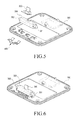
- FIG. 3 is a lateral view of a universal dock according to an exemplary embodiment of the present invention, after rotation of its connector.
- the universal dock 10 includes a base supporter 100, a universal cradle 200, and a connector 300.
- the base supporter 100 is placed on a table, and the cradle 200 is coupled to the base supporter 100 in a slanted position.
- the connector 300 is mounted on the cradle 200 and is always exposed.
- FIG. 2 shows the connector 300 when it stands upright with no external force acting on it according to an exemplary embodiment of the present invention
- FIG. 3 shows the connector 300 when it is acted on by an external force and rotated by a predetermined angle rearward according to an exemplary embodiment of the present invention.
- Reference numeral 110 in FIG. 1 refers to an opening.
- FIG. 4 is an exploded perspective view of a universal dock according to an exemplary embodiment of the present invention.
- the base supporter 100 has a pair of hinge arms 120 and 122 in the front area to enable rotation of a housing 350.
- the hinge arms 120 and 122 extend in the transverse direction.
- the cradle 200 is mounted on the base supporter 100 to support mobile phones of various sizes or types at a predetermined angle. Specifically, the cradle 200, when retaining a mobile phone, contacts and supports an area of the mobile phone below its middle (i.e., lower portion). The cradle may contact only the lower half of a mobile phone. For example, FIG. 10 shows a mobile phone retained on the cradle 200 in a slanted position.
- the cradle may support only up to the lower third, or lower quarter, or lower fifth portion of the mobile phone 500. Reducing the part of the mobile phone 500 that is in contact with the cradle 200 advantageously reduces the part of the cradle that is visible to the user.
- the cradle 200 includes a base 210 and a supporter 220 extending integrally from the base 210 in a predetermined direction.
- the connector 300 is rotatably received and arranged in the base 210, which is fixed to the base supporter 100.
- the base 210 is fixed to the base supporter 100 in a slanted position.
- the base 210 has an opening 212 for receiving the housing 350, to which the connector 300 is fixed, and a number of fasteners 214, e.g. hooks, positioned on the lower end to be fixed to the base supporter 100.
- the supporter 220 extends from the base 210 in an approximately perpendicular direction so that, when the base 210 is mounted on the platform in a slanted position, the supporter 220 extends a predetermined length from the base supporter 100 in a slanted direction.
- the supporter 220 has a plate shape, and is adapted to retain a mobile phone, which is connected to the connector 300, in a slanted position. That is, the supporter 220 contacts and supports the bottom surface of the retained mobile phone.
- the connector 300 which is a universal connector, is received in the base 210 and mounted so as to rotate.
- FIG. 2 shows the connector 300 prior to rotation
- FIG. 3 shows the connector 300 after rotation.
- the housing 350 is adapted to receive the connector 300 and rotate it inside the base, and has hinges 351 and 352 on both lateral ends, respectively.
- the housing 350 is supported by an elastic body 400, which exerts force so as to return the housing 350 to its initial position as shown in FIG. 2 .
- the elastic body 400 is mounted inside the base 210 and is positioned to remain forced against a predetermined portion of the housing 350, thereby providing force so as to always move the housing 350 towards its original position.
- the elastic body 400 has the shape of a leaf spring and includes a number of fixed ends 410, 411, and 412 and at least one free end 413 and 414.
- the fixed ends 410, 411, and 412 are fastened and fixed to the base 210, and the free ends 413 and 414 are positioned to be forced against the outer surface of the housing 350. Rotation of the housing 350 is followed by sliding of the free ends 413 and 414 on the outer surface of the housing.
- the free ends include left and right free ends 413 and 414 extending from the left and right fixed ends 411 and 412 in a perpendicular direction, respectively.
- the left and right free ends 413 and 414 are symmetric to each other, and are forced against the outer surface of the housing 350 symmetrically.
- the left and right free ends 413 and 414 have curved shapes, so that they can smoothly slide on the outer surface of the housing 350.
- the left and right fixed ends 411 and 412 are obtained by bending left and right extensions of the center fixed end 410 twice, respectively, and the left and right free ends 413 and 414 are obtained by bending extensions of the left and right fixed ends 411 and 412 a number of times, respectively.
- FIG. 5 is a perspective view of a universal dock according to an exemplary embodiment of the present invention, prior to mounting of a connector.
- FIG. 6 is a perspective view of a universal dock according to an exemplary embodiment of the present invention, after mounting of a connector.
- the connector is fixed to the housing, and the hinges of the housing are positioned on the support of the base, with the elastic body mounted between the housing and the base.
- the fixed ends of the elastic body are fixed by fasteners (not shown).
- FIG. 7 when the elastic body 400 is mounted on the base 210, the left and right free ends 413 and 414 remain forced against the outer surface of the housing 350, specifically its bottom surface, and support the housing 350 in the upright position.
- an external force acts on the housing 350, for example, when a mobile phone connects to the connector 300 and rotates due to its own weight, the left and right free ends 413 and 414 move approximately downwards and remain forced against a predetermined area of the bottom surface of the housing 350, thereby supporting the rotated housing 350.
- the elastic body 400 returns the housing 350 to its initial position as shown in FIG. 7 .
- the force necessary to return the housing 350 is provided by the elastic body 400.
- a predetermined portion of the outer surface of the housing 350 and the left and right free ends 413 and 414 make a sliding surface contact.
- FIG. 9 is a lateral view of a universal dock according to an exemplary embodiment of the present invention, before a mobile phone is connected to its connector.
- FIG. 10 is a lateral view of a universal dock according to an exemplary embodiment of the present invention, after a mobile phone is connected to its connector, rotated, and retained on the cradle in a slanted position.
- a process of retaining a mobile phone 500 on the universal dock will now be described with reference to FIGs. 9 and 10 .
- the connector 300 rotates due to the weight of the mobile phone 500, and the connected mobile phone 500 remains supported by the cradle 200.
- the elastic body returns the connector 300 to the upright position.
- the universal dock according to the present invention can retain mobile phones of various sizes or types, and thus has economical merits from the viewpoint of either users or manufacturers.
Landscapes
- Engineering & Computer Science (AREA)
- Theoretical Computer Science (AREA)
- Computer Hardware Design (AREA)
- General Engineering & Computer Science (AREA)
- Human Computer Interaction (AREA)
- Physics & Mathematics (AREA)
- General Physics & Mathematics (AREA)
- Signal Processing (AREA)
- Power Engineering (AREA)
- Telephone Set Structure (AREA)
- Connector Housings Or Holding Contact Members (AREA)
Abstract
Description
- The present invention relates to a mobile phone. More particularly, the present invention relates to a desktop-type universal dock capable of charging or retaining mobile phones of various sizes or types.
- In general, a mobile phone refers to a cellular phone, a Personal Digital Assistant (PDA), a smart phone, a tablet Personal Computer (PC), etc. A mobile phone can be used, when the power is depleted, after being recharged using a charging cradle, which can retain the mobile phone at an angle in a TV mode or Digital Multimedia Broadcasting (DMB) mode so that the user can conveniently watch the screen of the display unit.
- The mobile phone has an embedded or releasable battery, which is recharged by a charging cradle when power is used up. The charging cradle can retain the mobile phone in a horizontal or vertical position, but typically in a slanted position.
- There are various types of charging cradles, a typical example of which includes a dedicated receiving space, in which a mobile phone rests, and a connector for connection with a charging terminal of the mobile phone or with a charging terminal of a separate auxiliary battery pack.
- However, conventional cradles for mobile phones have a problem in that mobile phones of different specifications require dedicated charging cradles, meaning that, when a user needs to replace his/her malfunctioning or missing mobile phone, a dedicated charging cradle also needs to be purchased, which is uneconomical.
- Furthermore, each manufacturer makes a different charging cradle, or each cell phone model requires its own charging cradle. The fact that a dedicated charging cradle needs to be manufactured for each mobile phone increases the manufacturing cost.
- Therefore, a need exists for a universal dock for a mobile phone.
- Aspects of the present invention are to address at least the above-mentioned problems and/or disadvantages and to provide at least the advantages described below. Accordingly, an aspect of the present invention is to provide a (desktop-type) universal dock capable of retaining a mobile phone with no limitation on the mobile phone's overall size (transverse size, longitudinal size, thickness) or type (bar type, sliding type, folder type, etc.), thereby improving user convenience.
- With "universal dock" is meant that the dock supports various sizes and types of mobile phone. In particular, the universal dock supports a variety of conventional mobile phones. With "conventional mobile phone" is meant a mobile phone that has dimensions (transverse size, longitudinal size, thickness), weight, form factors, etc that are commonly accepted for a mobile phone.
- Another aspect of the present invention is to provide a desktop-type universal dock which can be manufactured at a lower cost, thereby giving its manufacturer economic merits.
- In accordance with an aspect of the present invention, a universal dock for a mobile phone is provided. The universal dock includes a base supporter, a universal cradle coupled to the base supporter and adapted to cradle mobile phones of various sizes or types, and a connector rotatably mounted on the universal cradle.
- In accordance with another aspect of the present invention, a universal dock for a mobile phone is provided. The universal dock includes a base supporter, a universal cradle coupled to the base supporter in a slanted position and adapted to cradle mobile phones of various sizes or types, a connector rotatably mounted on the universal cradle by a housing, and an elastic body mounted on the base supporter and adapted to remain forced against the housing and to support the connector so that the connector returns, in the absence of external forces, to a predetermined state. Further advantageous embodiments of the invention are defined in the appended claims.
- Aspects, advantages, and salient features of the invention will become apparent to those skilled in the art from the following detailed description, which, taken in conjunction with the annexed drawings, discloses exemplary embodiments of the invention.
- The above and other aspects, features, and advantages of certain exemplary embodiments of the present invention will be more apparent from the following description taken in conjunction with the accompanying drawings, in which:
-
FIG. 1 is an assembled perspective view of a universal dock according to an exemplary embodiment of the present invention; -
FIG. 2 is a lateral view of a universal dock according to an exemplary embodiment of the present invention, prior to rotation of its connector; -
FIG. 3 is a lateral view of a universal dock according to an exemplary embodiment of the present invention, after rotation of its connector; -
FIG. 4 is an exploded perspective view of a universal dock according to an exemplary embodiment of the present invention; -
FIG. 5 is a perspective view of a universal dock according to an exemplary embodiment of the present invention, prior to mounting of a connector; -
FIG. 6 is a perspective view of a universal dock according to an exemplary embodiment of the present invention, after mounting of a connector; -
FIG. 7 is a sectional view of a universal dock according to an exemplary embodiment of the present invention, prior to rotation of its connector; -
FIG. 8 is a sectional view of a universal dock according to an exemplary embodiment of the present invention, after rotation of its connector; -
FIG. 9 is a lateral view of a universal dock according to an exemplary embodiment of the present invention, before a mobile phone is connected to its connector; and -
FIG. 10 is a lateral view of a universal dock according to an exemplary embodiment of the present invention, after a mobile phone is connected to its connector, rotated, and retained on the cradle in a slanted position. - Throughout the drawings, it should be noted that like reference numbers are used to depict the same or similar elements, features, and structures.
- The following description with reference to the accompanying drawings is provided to assist in a comprehensive understanding of exemplary embodiments of the invention as defined by the claims and their equivalents. It includes various specific details to assist in that understanding but these are to be regarded as merely exemplary. Accordingly, those of ordinary skill in the art will recognize that various changes and modifications of the embodiments described herein can be made without departing from the scope and spirit of the invention. In addition, descriptions of well-known functions and constructions may be omitted for clarity and conciseness.
- The terms and words used in the following description and claims are not limited to the bibliographical meanings, but, are merely used by the inventor to enable a clear and consistent understanding of the invention. Accordingly, it should be apparent to those skilled in the art that the following description of exemplary embodiments of the present invention is provided for illustration purpose only and not for the purpose of limiting the invention as defined by the appended claims and their equivalents.
- It is to be understood that the singular forms "a," "an," and "the" include plural referents unless the context clearly dictates otherwise. Thus, for example, reference to "a component surface" includes reference to one or more of such surfaces.
-
FIG. 1 is an assembled perspective view of a universal dock according to an exemplary embodiment of the present invention. -
FIG. 1 shows a universal dock according to an exemplary embodiment of the present invention with reference to a three-dimensional Cartesian coordinate system, wherein the X-axis corresponds to the left/right (transverse) direction of the dock, the Y-axis corresponds to the front/rear (longitudinal) direction of the dock, and the Z-axis corresponds to the up/down (vertical) direction of the dock. - Referring to
FIG. 1 , auniversal dock 10 according to an exemplary embodiment of the present invention is used as a cradle or a charging cradle for a mobile phone, and more specifically as a cradle or a charging cradle for mobile phones of various sizes or types. As used herein, mobile phones of various sizes refer to mobile phones having various dimensions of transverse length, longitudinal length, and thickness. This means that theuniversal dock 10 according to an exemplary embodiment of the present invention is independent of the mobile phone size, in terms of mobile phone retaining, so that it can retain a mobile phone of any transverse length/longitudinal length/thickness at a predetermined angle. - In addition, mobile phones of various types include, in terms of appearance, bar types, sliding types, folder types, etc., as well as cellular phones, Personal Digital Assistants (PDAs), smart phones, tablet Personal Computers (PCs), electronic books, Motion Picture Experts Group (MPEG)-2 Audio Layer III (MP3) players, etc.
-
FIG. 2 is a lateral view of a universal dock according to an exemplary embodiment of the present invention, prior to rotation of its connector.FIG. 3 is a lateral view of a universal dock according to an exemplary embodiment of the present invention, after rotation of its connector. - Referring to
FIGs. 1-3 , theuniversal dock 10 includes abase supporter 100, auniversal cradle 200, and aconnector 300. Thebase supporter 100 is placed on a table, and thecradle 200 is coupled to thebase supporter 100 in a slanted position. Theconnector 300 is mounted on thecradle 200 and is always exposed.FIG. 2 shows theconnector 300 when it stands upright with no external force acting on it according to an exemplary embodiment of the present invention, andFIG. 3 shows theconnector 300 when it is acted on by an external force and rotated by a predetermined angle rearward according to an exemplary embodiment of the present invention.Reference numeral 110 inFIG. 1 refers to an opening. -
FIG. 4 is an exploded perspective view of a universal dock according to an exemplary embodiment of the present invention. - Referring to
FIG. 4 , thebase supporter 100 has a pair ofhinge arms housing 350. Thehinge arms cradle 200 is mounted on thebase supporter 100 to support mobile phones of various sizes or types at a predetermined angle. Specifically, thecradle 200, when retaining a mobile phone, contacts and supports an area of the mobile phone below its middle (i.e., lower portion). The cradle may contact only the lower half of a mobile phone. For example,FIG. 10 shows a mobile phone retained on thecradle 200 in a slanted position. The cradle may support only up to the lower third, or lower quarter, or lower fifth portion of themobile phone 500. Reducing the part of themobile phone 500 that is in contact with thecradle 200 advantageously reduces the part of the cradle that is visible to the user. - The
cradle 200 includes abase 210 and asupporter 220 extending integrally from the base 210 in a predetermined direction. Theconnector 300 is rotatably received and arranged in thebase 210, which is fixed to thebase supporter 100. Thebase 210 is fixed to thebase supporter 100 in a slanted position. Thebase 210 has an opening 212 for receiving thehousing 350, to which theconnector 300 is fixed, and a number offasteners 214, e.g. hooks, positioned on the lower end to be fixed to thebase supporter 100. - The
supporter 220 extends from the base 210 in an approximately perpendicular direction so that, when thebase 210 is mounted on the platform in a slanted position, thesupporter 220 extends a predetermined length from thebase supporter 100 in a slanted direction. Thesupporter 220 has a plate shape, and is adapted to retain a mobile phone, which is connected to theconnector 300, in a slanted position. That is, thesupporter 220 contacts and supports the bottom surface of the retained mobile phone. - The
connector 300, which is a universal connector, is received in thebase 210 and mounted so as to rotate.FIG. 2 shows theconnector 300 prior to rotation, andFIG. 3 shows theconnector 300 after rotation. - The
housing 350 is adapted to receive theconnector 300 and rotate it inside the base, and hashinges housing 350 is supported by anelastic body 400, which exerts force so as to return thehousing 350 to its initial position as shown inFIG. 2 . - The
elastic body 400 is mounted inside thebase 210 and is positioned to remain forced against a predetermined portion of thehousing 350, thereby providing force so as to always move thehousing 350 towards its original position. Theelastic body 400 has the shape of a leaf spring and includes a number of fixed ends 410, 411, and 412 and at least onefree end base 210, and the free ends 413 and 414 are positioned to be forced against the outer surface of thehousing 350. Rotation of thehousing 350 is followed by sliding of the free ends 413 and 414 on the outer surface of the housing. There are three fixed ends, including a center fixedend 410 and left and right fixed ends 411 and 412. The free ends include left and right free ends 413 and 414 extending from the left and right fixed ends 411 and 412 in a perpendicular direction, respectively. The left and right free ends 413 and 414 are symmetric to each other, and are forced against the outer surface of thehousing 350 symmetrically. The left and right free ends 413 and 414 have curved shapes, so that they can smoothly slide on the outer surface of thehousing 350. The left and right fixed ends 411 and 412 are obtained by bending left and right extensions of the center fixedend 410 twice, respectively, and the left and right free ends 413 and 414 are obtained by bending extensions of the left and right fixed ends 411 and 412 a number of times, respectively. -
FIG. 5 is a perspective view of a universal dock according to an exemplary embodiment of the present invention, prior to mounting of a connector.FIG. 6 is a perspective view of a universal dock according to an exemplary embodiment of the present invention, after mounting of a connector. - Referring to
FIGs. 5 and 6 , the connector is fixed to the housing, and the hinges of the housing are positioned on the support of the base, with the elastic body mounted between the housing and the base. The fixed ends of the elastic body are fixed by fasteners (not shown). - Rotation operations of the
housing 350, on which theconnector 300 is mounted, will be described with reference toFIGs. 7 and 8 . As shown inFIG. 7 , when theelastic body 400 is mounted on thebase 210, the left and right free ends 413 and 414 remain forced against the outer surface of thehousing 350, specifically its bottom surface, and support thehousing 350 in the upright position. When an external force acts on thehousing 350, for example, when a mobile phone connects to theconnector 300 and rotates due to its own weight, the left and right free ends 413 and 414 move approximately downwards and remain forced against a predetermined area of the bottom surface of thehousing 350, thereby supporting the rotatedhousing 350. When the mobile phone is disconnected from theconnector 300, theelastic body 400 returns thehousing 350 to its initial position as shown inFIG. 7 . The force necessary to return thehousing 350 is provided by theelastic body 400. During rotation of theconnector 300, a predetermined portion of the outer surface of thehousing 350 and the left and right free ends 413 and 414 make a sliding surface contact. -
FIG. 9 is a lateral view of a universal dock according to an exemplary embodiment of the present invention, before a mobile phone is connected to its connector.FIG. 10 is a lateral view of a universal dock according to an exemplary embodiment of the present invention, after a mobile phone is connected to its connector, rotated, and retained on the cradle in a slanted position. - A process of retaining a
mobile phone 500 on the universal dock will now be described with reference toFIGs. 9 and10 . When themobile phone 500 is connected to theconnector 300, theconnector 300 rotates due to the weight of themobile phone 500, and the connectedmobile phone 500 remains supported by thecradle 200. As described above, when themobile phone 500 is disconnected from theconnector 300, the elastic body returns theconnector 300 to the upright position. - As described above, the universal dock according to the present invention can retain mobile phones of various sizes or types, and thus has economical merits from the viewpoint of either users or manufacturers.
- While the invention has been shown and described with reference to certain exemplary embodiments thereof, it will be understood by those skilled in the art that various changes in form and details may be made therein without departing from the spirit and scope of the invention as defined by the appended claims and their equivalents.
Claims (13)
- A universal dock (10) for a mobile phone (500), characterized by:a base supporter (100);a universal cradle (200) coupled to the base supporter (100) and adapted to cradle any one mobile phones (500) from a set of mobile phones of various sizes or types; anda connector (300) for connecting to the mobile phone (500), said connector being rotatably mounted on the universal cradle (200).
- The universal dock (10) as claimed in claim 1, characterized in that the cradle (200) is adapted to support a lower portion of the mobile phone (500), such as the lower half of the mobile phone (500).
- The universal dock (10) as claimed in claim 1 or 2, characterized in that the cradle (200) comprises:a base (210) coupled to the base supporter (100) in a slanted position, the connector (300) being rotatably received and arranged in the base (210); anda supporter (220) extending from the base (210) in a substantially perpendicular direction to be positioned on the base supporter (100) in a slanted position, the supporter (220) being adapted to retain a mobile phone (500), when connected to the connector (300), in a slanted position.
- The universal dock (10) as claimed in claim 3, characterized in that the mobile phone (500), when connected to the connector (300), is rotated due to its own weight to be cradled on the support (220) in a slanted position.
- The universal dock (10) as claimed in any of the previous claims, characterized in that the cradle is adapted so that a conventional mobile phone (500) can be cradled on the cradle (200) independent of a conventional transverse length, longitudinal length, and thickness of the mobile phone.
- The universal dock (10) as claimed in any of the previous claims, characterized in that the connector (300) is rotatably mounted on the base supporter (100) by a housing (350).
- The universal dock (10) as claimed in claim 6, characterized in that the base (210) further comprises an elastic body (400) exerting force against a predetermined portion of the housing (350), and wherein the elastic body (400) is adapted to provide the force so as to maintain the connector (300) in an upright position.
- The universal dock (10) as claimed in claim 7, characterized in that the elastic body (400) comprises a shape of a leaf spring, and comprises:at least one fixed end (410, 411, 412) fixed inside the base (210); andat least one curved free end (413, 414) extending from the fixed end (411, 412), the curved free end (413, 414) being positioned to be forced against a predetermined portion of the housing (350) so as to make a sliding surface contact when the predetermined portion of the housing (350) rotates.
- The universal dock (10) as claimed in claim 8, characterized in that the fixed end comprises a center fixed end (410) fixed to the base (210) and left and right fixed ends (411, 412) symmetrically positioned on both sides of the center fixed end (410), respectively, the left and right fixed ends (411, 412) being formed by bending extensions from the center fixed end (410), and
the free end comprises left and right free ends (413, 414) extending from the left and right fixed ends (411, 412), respectively, the left and right free ends (411, 412) being formed by bending extensions from the left and right fixed ends (411,412). - The universal dock (10) as claimed in claim 9, characterized in that the left and right free ends (413, 414) are adapted to move substantially upwards/downwards inside the base (210) when the cradled mobile phone (500) rotates.
- A universal dock (10) as claimed in claims 1, 2, or 3,
wherein the universal cradle (200) is coupled to the base supporter (100) in a slanted position and the connector (300) is rotatably mounted on the universal cradle (200) by a housing (350); and wherein
an elastic body (400) is mounted on the base supporter (100) and adapted to remain forced against the housing (350) and to support the connector (300) so that the connector (300) returns to a predetermined state when released from an external force such as the weight of a connected mobile phone. - The universal dock (10) as claimed in claim 11, characterized in that the predetermined state of the connector (300) comprises an upright state.
- The universal dock (10) as claimed in claim 11 or 12, characterized in that the mobile phone (500) is structured so that, when connected to the connector (300), the mobile phone (500) rotates due to its own weight and is supported on the universal cradle (200).
Applications Claiming Priority (1)
| Application Number | Priority Date | Filing Date | Title |
|---|---|---|---|
| KR1020120015608A KR20130094402A (en) | 2012-02-16 | 2012-02-16 | Desk top-type universal dock |
Publications (3)
| Publication Number | Publication Date |
|---|---|
| EP2629172A2 true EP2629172A2 (en) | 2013-08-21 |
| EP2629172A3 EP2629172A3 (en) | 2016-03-16 |
| EP2629172B1 EP2629172B1 (en) | 2018-01-03 |
Family
ID=47900517
Family Applications (1)
| Application Number | Title | Priority Date | Filing Date |
|---|---|---|---|
| EP13155474.3A Not-in-force EP2629172B1 (en) | 2012-02-16 | 2013-02-15 | Desktop-type universal dock |
Country Status (4)
| Country | Link |
|---|---|
| US (1) | US9118749B2 (en) |
| EP (1) | EP2629172B1 (en) |
| KR (1) | KR20130094402A (en) |
| CN (1) | CN103259893B (en) |
Cited By (4)
| Publication number | Priority date | Publication date | Assignee | Title |
|---|---|---|---|---|
| EP3062402A1 (en) * | 2015-02-27 | 2016-08-31 | Samsung Electronics Co., Ltd. | Connector module and locking device including the same |
| NO20171893A1 (en) * | 2017-11-27 | 2019-05-28 | Customme As | Charger for charging of a mobile device |
| US20220045528A1 (en) * | 2020-08-10 | 2022-02-10 | Bsh Hausgeraete Gmbh | Docking station with detachable back support |
| RU218322U1 (en) * | 2022-11-22 | 2023-05-22 | Общество с ограниченной ответственностью "КЕМБОСС" | Mobile phone stand |
Families Citing this family (43)
| Publication number | Priority date | Publication date | Assignee | Title |
|---|---|---|---|---|
| WO2012094526A1 (en) | 2011-01-05 | 2012-07-12 | Mophie, Inc. | Tablet computer stand |
| JP5637567B2 (en) | 2012-09-26 | 2014-12-10 | Necプラットフォームズ株式会社 | Cradle device |
| TWM460316U (en) * | 2013-04-24 | 2013-08-21 | Quanta Comp Inc | Supporting structure and electronic device using the same |
| US9545549B2 (en) | 2013-05-15 | 2017-01-17 | Cobra Golf Incorporated | Golf bag with a docking station for an electronic device |
| USD741334S1 (en) * | 2013-08-01 | 2015-10-20 | Unify Gmbh & Co. Kg | Docking station for telephone and flat computer |
| WO2015054242A1 (en) * | 2013-10-09 | 2015-04-16 | Mophie, Inc. | Dock station with movable support |
| USD712369S1 (en) * | 2013-12-16 | 2014-09-02 | Panasonic Corporation | Telephone base unit |
| USD722062S1 (en) * | 2014-07-02 | 2015-02-03 | Evernote Corporation | Tablet dish |
| TWI562478B (en) * | 2014-09-24 | 2016-12-11 | Hon Hai Prec Ind Co Ltd | Connector device |
| US10437288B2 (en) | 2014-10-06 | 2019-10-08 | Fasetto, Inc. | Portable storage device with modular power and housing system |
| CN204190438U (en) * | 2014-10-22 | 2015-03-04 | 深圳沃鹏无线科技有限公司 | A kind of stent-type wireless charger |
| USD806022S1 (en) * | 2015-01-06 | 2017-12-26 | John Paul Waring | Charging station |
| CN204350081U (en) * | 2015-01-22 | 2015-05-20 | 京东方光科技有限公司 | Portable type electronic product |
| US9338903B1 (en) | 2015-01-27 | 2016-05-10 | John Loscalzo | Mobile device cradle |
| USD791072S1 (en) * | 2015-09-07 | 2017-07-04 | Gibson Innovations Belgium Nv | Charging stand |
| CN105226756A (en) * | 2015-10-27 | 2016-01-06 | 苏州凯丰电子电器有限公司 | A kind of handset charging holder easy to use |
| JP1561255S (en) * | 2015-12-18 | 2016-10-24 | ||
| CN107404555A (en) * | 2016-05-21 | 2017-11-28 | 麦广树 | Handset mounting with width adaptive mechanism |
| USD841576S1 (en) * | 2016-09-02 | 2019-02-26 | Design Pool Limited | Charging dock |
| CN210838302U (en) * | 2016-10-07 | 2020-06-23 | 菲力尔系统公司 | electronic module |
| CN107919549B (en) * | 2016-10-10 | 2020-05-19 | 神讯电脑(昆山)有限公司 | Transmission base of electronic device |
| US9742455B1 (en) * | 2016-10-18 | 2017-08-22 | Getac Technology Corporation | Transmission dock of electronic device |
| CN110461658A (en) | 2017-02-03 | 2019-11-15 | 法斯埃托股份有限公司 | Systems and methods for data storage in keyed devices |
| USD847739S1 (en) * | 2017-04-28 | 2019-05-07 | Spigen Korea Co., Ltd. | Charging stand for electronic devices |
| US10763630B2 (en) * | 2017-10-19 | 2020-09-01 | Fasetto, Inc. | Portable electronic device connection systems |
| AU2018374384A1 (en) | 2017-12-01 | 2020-07-23 | Fasetto, Inc. | Systems and methods for improved data encryption |
| USD859393S1 (en) | 2018-01-05 | 2019-09-10 | Mophie Inc. | Electronic device mount |
| JP6511178B1 (en) | 2018-03-02 | 2019-05-15 | 任天堂株式会社 | Power-on device |
| USD858530S1 (en) * | 2018-03-23 | 2019-09-03 | Gopod Group Ltd. | Multi-port docking station for mobile phone |
| MX2020010857A (en) | 2018-04-17 | 2021-01-15 | Fasetto Inc | DEVICE PRESENTATION WITH COMMENTS IN REAL TIME. |
| USD886827S1 (en) * | 2018-05-02 | 2020-06-09 | Ugreen Group Limited | Docking station |
| USD873260S1 (en) | 2018-06-22 | 2020-01-21 | Mophie Inc. | Mount for electronic device |
| USD873272S1 (en) | 2018-06-22 | 2020-01-21 | Mophie Inc. | Mount for electronic device |
| US10971875B2 (en) * | 2018-11-04 | 2021-04-06 | Kien Hoe Daniel Chin | Apparatus and method of securing adapters to a mobile device |
| US11014509B2 (en) | 2019-02-13 | 2021-05-25 | Mophie Inc. | Mount for holding a mobile electronic device |
| USD896226S1 (en) * | 2019-03-18 | 2020-09-15 | Shenzhen Guli Technology Co., Ltd | Magnetic dock set |
| WO2022090678A1 (en) * | 2020-11-02 | 2022-05-05 | Securinet | Alert device for a person in a dangerous situation and its method of use by psychological conditioning |
| US20220416554A1 (en) * | 2021-06-23 | 2022-12-29 | Tatung Technology Inc. | Charging stand, electronic apparatus, and method for operating charging stand |
| USD1021774S1 (en) * | 2022-03-16 | 2024-04-09 | Microsoft Corporation | Charging dock |
| JP1754823S (en) * | 2022-09-30 | 2023-10-10 | Wireless charging cradle for smartwatch | |
| USD1087903S1 (en) * | 2023-07-13 | 2025-08-12 | Shenzhen Colorii TECH Limited | Combined stand and docking for game tablet |
| USD1083932S1 (en) * | 2024-01-04 | 2025-07-15 | Ugreen Group Limited | Docking station |
| US12385594B1 (en) * | 2025-03-10 | 2025-08-12 | Pioneer Square Brands, Inc. | Stand system for portable electronic device |
Family Cites Families (19)
| Publication number | Priority date | Publication date | Assignee | Title |
|---|---|---|---|---|
| US6457996B1 (en) * | 2001-06-22 | 2002-10-01 | Jess-Link Products Co., Ltd. | Connector to PDA external keyboard |
| US7477919B2 (en) * | 2002-09-19 | 2009-01-13 | Peter Warren | Handheld input/output device providing enhanced user interface for a mobile telephone |
| TWM255438U (en) * | 2004-04-12 | 2005-01-11 | Uniwill Comp Corp | Improved extended device for a portable electronic device |
| KR100663535B1 (en) * | 2004-05-17 | 2007-01-02 | 삼성전자주식회사 | Speaker-compatible interchangeable mount / charger for portable devices |
| US7061757B2 (en) * | 2004-08-02 | 2006-06-13 | Uniwill Computer Corp. | Port replicator for portable electronic devices |
| US7764784B2 (en) * | 2004-09-08 | 2010-07-27 | Cradlepoint, Inc. | Handset cradle |
| US20070038434A1 (en) * | 2005-01-05 | 2007-02-15 | Jonatan Cvetko | Universal system interface |
| US20060181840A1 (en) * | 2005-01-05 | 2006-08-17 | Jonatan Cvetko | Cradle for portable devices on a vehicle |
| US7643283B2 (en) * | 2007-09-07 | 2010-01-05 | Microsoft Corporation | Adaptive dock for use with personal media players |
| KR101420876B1 (en) * | 2007-11-16 | 2014-07-17 | 삼성전자주식회사 | A holder of a portable terminal |
| US8559172B2 (en) * | 2008-05-02 | 2013-10-15 | Norman R. Byrne | Docking station |
| CA2726477C (en) * | 2008-06-09 | 2017-02-14 | Norman R. Byrne | Docking station for use with power and data center |
| US20110099507A1 (en) * | 2009-10-28 | 2011-04-28 | Google Inc. | Displaying a collection of interactive elements that trigger actions directed to an item |
| KR101701922B1 (en) * | 2009-11-17 | 2017-02-02 | 삼성전자 주식회사 | Docking apparatus for portable device |
| US8202114B2 (en) * | 2009-12-14 | 2012-06-19 | Mitac International Corp. | Mobile phone cradle with three-point retention of portable electronic device installed in the cradle |
| US8223483B2 (en) * | 2010-01-04 | 2012-07-17 | Apple Inc. | Dock with moveable connector for display device |
| US20120302288A1 (en) * | 2011-05-23 | 2012-11-29 | Joe Born | Cellular Telephone Docking Interface |
| JP2013025885A (en) * | 2011-07-15 | 2013-02-04 | Sony Corp | Connection device |
| KR101892082B1 (en) * | 2012-03-13 | 2018-08-28 | 삼성전자주식회사 | Universal dock for portable phone |
-
2012
- 2012-02-16 KR KR1020120015608A patent/KR20130094402A/en not_active Ceased
-
2013
- 2013-01-30 US US13/753,898 patent/US9118749B2/en not_active Expired - Fee Related
- 2013-02-15 EP EP13155474.3A patent/EP2629172B1/en not_active Not-in-force
- 2013-02-16 CN CN201310051351.0A patent/CN103259893B/en not_active Expired - Fee Related
Non-Patent Citations (1)
| Title |
|---|
| None |
Cited By (7)
| Publication number | Priority date | Publication date | Assignee | Title |
|---|---|---|---|---|
| EP3062402A1 (en) * | 2015-02-27 | 2016-08-31 | Samsung Electronics Co., Ltd. | Connector module and locking device including the same |
| US9742107B2 (en) | 2015-02-27 | 2017-08-22 | Samsung Electronics Co., Ltd. | Connector module and locking device including the same |
| NO20171893A1 (en) * | 2017-11-27 | 2019-05-28 | Customme As | Charger for charging of a mobile device |
| NO343978B1 (en) * | 2017-11-27 | 2019-08-05 | Customme As | Charger for charging of a mobile device |
| US20220045528A1 (en) * | 2020-08-10 | 2022-02-10 | Bsh Hausgeraete Gmbh | Docking station with detachable back support |
| US11817729B2 (en) * | 2020-08-10 | 2023-11-14 | Bsh Hausgeraete Gmbh | Docking station with detachable back support |
| RU218322U1 (en) * | 2022-11-22 | 2023-05-22 | Общество с ограниченной ответственностью "КЕМБОСС" | Mobile phone stand |
Also Published As
| Publication number | Publication date |
|---|---|
| CN103259893B (en) | 2017-07-18 |
| KR20130094402A (en) | 2013-08-26 |
| EP2629172B1 (en) | 2018-01-03 |
| CN103259893A (en) | 2013-08-21 |
| EP2629172A3 (en) | 2016-03-16 |
| US20130217448A1 (en) | 2013-08-22 |
| US9118749B2 (en) | 2015-08-25 |
Similar Documents
| Publication | Publication Date | Title |
|---|---|---|
| US9118749B2 (en) | Desktop-type universal dock | |
| US9318906B2 (en) | Universal dock for portable phone | |
| KR102251255B1 (en) | Multi-purpose interface for a portable electronic device | |
| US20170205852A1 (en) | Apparatus for port expansion | |
| GB2487482A (en) | Tablet computer and media player docking station with collapsible support | |
| US20140049851A1 (en) | Device and related systems and methods for securing accessories to hand held electronic devices | |
| US9207714B2 (en) | Support for a portable electronic device | |
| CN114484172B (en) | Support and terminal equipment subassembly | |
| CN218348348U (en) | Support and electronic device | |
| CN108413225A (en) | mobile terminal stand | |
| CN103425196A (en) | Electronic device | |
| CN201717903U (en) | Mobile terminal | |
| KR20130005046U (en) | Tablet pc case | |
| CN212115396U (en) | Foldable mobile phone desktop support | |
| KR101908013B1 (en) | Desk top-type universal dock | |
| CN211908882U (en) | Mobile terminal support and protective housing | |
| CN209962173U (en) | Docking station with wireless charging function | |
| CN203424508U (en) | Protective sleeve | |
| CN212929310U (en) | Support frame | |
| KR20120015146A (en) | Portable device holder | |
| CN221428960U (en) | Light filling lamp for cell-phone | |
| CN218497418U (en) | Mobile intelligent terminal protective sleeve | |
| CN116937725B (en) | Charging stand | |
| KR200484140Y1 (en) | Portable device holder | |
| CN217402207U (en) | Support frame |
Legal Events
| Date | Code | Title | Description |
|---|---|---|---|
| PUAI | Public reference made under article 153(3) epc to a published international application that has entered the european phase |
Free format text: ORIGINAL CODE: 0009012 |
|
| AK | Designated contracting states |
Kind code of ref document: A2 Designated state(s): AL AT BE BG CH CY CZ DE DK EE ES FI FR GB GR HR HU IE IS IT LI LT LU LV MC MK MT NL NO PL PT RO RS SE SI SK SM TR |
|
| AX | Request for extension of the european patent |
Extension state: BA ME |
|
| PUAL | Search report despatched |
Free format text: ORIGINAL CODE: 0009013 |
|
| AK | Designated contracting states |
Kind code of ref document: A3 Designated state(s): AL AT BE BG CH CY CZ DE DK EE ES FI FR GB GR HR HU IE IS IT LI LT LU LV MC MK MT NL NO PL PT RO RS SE SI SK SM TR |
|
| AX | Request for extension of the european patent |
Extension state: BA ME |
|
| RIC1 | Information provided on ipc code assigned before grant |
Ipc: H04M 1/04 20060101ALI20160210BHEP Ipc: G06F 1/16 20060101AFI20160210BHEP Ipc: H02J 7/00 20060101ALI20160210BHEP |
|
| 17P | Request for examination filed |
Effective date: 20160810 |
|
| RBV | Designated contracting states (corrected) |
Designated state(s): AL AT BE BG CH CY CZ DE DK EE ES FI FR GB GR HR HU IE IS IT LI LT LU LV MC MK MT NL NO PL PT RO RS SE SI SK SM TR |
|
| GRAP | Despatch of communication of intention to grant a patent |
Free format text: ORIGINAL CODE: EPIDOSNIGR1 |
|
| INTG | Intention to grant announced |
Effective date: 20170718 |
|
| GRAS | Grant fee paid |
Free format text: ORIGINAL CODE: EPIDOSNIGR3 |
|
| GRAJ | Information related to disapproval of communication of intention to grant by the applicant or resumption of examination proceedings by the epo deleted |
Free format text: ORIGINAL CODE: EPIDOSDIGR1 |
|
| GRAL | Information related to payment of fee for publishing/printing deleted |
Free format text: ORIGINAL CODE: EPIDOSDIGR3 |
|
| GRAR | Information related to intention to grant a patent recorded |
Free format text: ORIGINAL CODE: EPIDOSNIGR71 |
|
| GRAA | (expected) grant |
Free format text: ORIGINAL CODE: 0009210 |
|
| INTC | Intention to grant announced (deleted) | ||
| INTG | Intention to grant announced |
Effective date: 20171122 |
|
| AK | Designated contracting states |
Kind code of ref document: B1 Designated state(s): AL AT BE BG CH CY CZ DE DK EE ES FI FR GB GR HR HU IE IS IT LI LT LU LV MC MK MT NL NO PL PT RO RS SE SI SK SM TR |
|
| REG | Reference to a national code |
Ref country code: GB Ref legal event code: FG4D |
|
| REG | Reference to a national code |
Ref country code: CH Ref legal event code: EP Ref country code: AT Ref legal event code: REF Ref document number: 960862 Country of ref document: AT Kind code of ref document: T Effective date: 20180115 |
|
| REG | Reference to a national code |
Ref country code: IE Ref legal event code: FG4D |
|
| REG | Reference to a national code |
Ref country code: DE Ref legal event code: R096 Ref document number: 602013031536 Country of ref document: DE |
|
| REG | Reference to a national code |
Ref country code: NL Ref legal event code: FP |
|
| REG | Reference to a national code |
Ref country code: LT Ref legal event code: MG4D |
|
| REG | Reference to a national code |
Ref country code: AT Ref legal event code: MK05 Ref document number: 960862 Country of ref document: AT Kind code of ref document: T Effective date: 20180103 |
|
| PG25 | Lapsed in a contracting state [announced via postgrant information from national office to epo] |
Ref country code: FI Free format text: LAPSE BECAUSE OF FAILURE TO SUBMIT A TRANSLATION OF THE DESCRIPTION OR TO PAY THE FEE WITHIN THE PRESCRIBED TIME-LIMIT Effective date: 20180103 Ref country code: LT Free format text: LAPSE BECAUSE OF FAILURE TO SUBMIT A TRANSLATION OF THE DESCRIPTION OR TO PAY THE FEE WITHIN THE PRESCRIBED TIME-LIMIT Effective date: 20180103 Ref country code: HR Free format text: LAPSE BECAUSE OF FAILURE TO SUBMIT A TRANSLATION OF THE DESCRIPTION OR TO PAY THE FEE WITHIN THE PRESCRIBED TIME-LIMIT Effective date: 20180103 Ref country code: CY Free format text: LAPSE BECAUSE OF FAILURE TO SUBMIT A TRANSLATION OF THE DESCRIPTION OR TO PAY THE FEE WITHIN THE PRESCRIBED TIME-LIMIT Effective date: 20180103 Ref country code: ES Free format text: LAPSE BECAUSE OF FAILURE TO SUBMIT A TRANSLATION OF THE DESCRIPTION OR TO PAY THE FEE WITHIN THE PRESCRIBED TIME-LIMIT Effective date: 20180103 Ref country code: NO Free format text: LAPSE BECAUSE OF FAILURE TO SUBMIT A TRANSLATION OF THE DESCRIPTION OR TO PAY THE FEE WITHIN THE PRESCRIBED TIME-LIMIT Effective date: 20180403 |
|
| PG25 | Lapsed in a contracting state [announced via postgrant information from national office to epo] |
Ref country code: IS Free format text: LAPSE BECAUSE OF FAILURE TO SUBMIT A TRANSLATION OF THE DESCRIPTION OR TO PAY THE FEE WITHIN THE PRESCRIBED TIME-LIMIT Effective date: 20180503 Ref country code: BG Free format text: LAPSE BECAUSE OF FAILURE TO SUBMIT A TRANSLATION OF THE DESCRIPTION OR TO PAY THE FEE WITHIN THE PRESCRIBED TIME-LIMIT Effective date: 20180403 Ref country code: AT Free format text: LAPSE BECAUSE OF FAILURE TO SUBMIT A TRANSLATION OF THE DESCRIPTION OR TO PAY THE FEE WITHIN THE PRESCRIBED TIME-LIMIT Effective date: 20180103 Ref country code: SE Free format text: LAPSE BECAUSE OF FAILURE TO SUBMIT A TRANSLATION OF THE DESCRIPTION OR TO PAY THE FEE WITHIN THE PRESCRIBED TIME-LIMIT Effective date: 20180103 Ref country code: LV Free format text: LAPSE BECAUSE OF FAILURE TO SUBMIT A TRANSLATION OF THE DESCRIPTION OR TO PAY THE FEE WITHIN THE PRESCRIBED TIME-LIMIT Effective date: 20180103 Ref country code: RS Free format text: LAPSE BECAUSE OF FAILURE TO SUBMIT A TRANSLATION OF THE DESCRIPTION OR TO PAY THE FEE WITHIN THE PRESCRIBED TIME-LIMIT Effective date: 20180103 Ref country code: GR Free format text: LAPSE BECAUSE OF FAILURE TO SUBMIT A TRANSLATION OF THE DESCRIPTION OR TO PAY THE FEE WITHIN THE PRESCRIBED TIME-LIMIT Effective date: 20180404 Ref country code: PL Free format text: LAPSE BECAUSE OF FAILURE TO SUBMIT A TRANSLATION OF THE DESCRIPTION OR TO PAY THE FEE WITHIN THE PRESCRIBED TIME-LIMIT Effective date: 20180103 |
|
| REG | Reference to a national code |
Ref country code: CH Ref legal event code: PL |
|
| REG | Reference to a national code |
Ref country code: DE Ref legal event code: R097 Ref document number: 602013031536 Country of ref document: DE |
|
| PG25 | Lapsed in a contracting state [announced via postgrant information from national office to epo] |
Ref country code: EE Free format text: LAPSE BECAUSE OF FAILURE TO SUBMIT A TRANSLATION OF THE DESCRIPTION OR TO PAY THE FEE WITHIN THE PRESCRIBED TIME-LIMIT Effective date: 20180103 Ref country code: IT Free format text: LAPSE BECAUSE OF FAILURE TO SUBMIT A TRANSLATION OF THE DESCRIPTION OR TO PAY THE FEE WITHIN THE PRESCRIBED TIME-LIMIT Effective date: 20180103 Ref country code: RO Free format text: LAPSE BECAUSE OF FAILURE TO SUBMIT A TRANSLATION OF THE DESCRIPTION OR TO PAY THE FEE WITHIN THE PRESCRIBED TIME-LIMIT Effective date: 20180103 Ref country code: MC Free format text: LAPSE BECAUSE OF FAILURE TO SUBMIT A TRANSLATION OF THE DESCRIPTION OR TO PAY THE FEE WITHIN THE PRESCRIBED TIME-LIMIT Effective date: 20180103 Ref country code: AL Free format text: LAPSE BECAUSE OF FAILURE TO SUBMIT A TRANSLATION OF THE DESCRIPTION OR TO PAY THE FEE WITHIN THE PRESCRIBED TIME-LIMIT Effective date: 20180103 |
|
| PLBE | No opposition filed within time limit |
Free format text: ORIGINAL CODE: 0009261 |
|
| STAA | Information on the status of an ep patent application or granted ep patent |
Free format text: STATUS: NO OPPOSITION FILED WITHIN TIME LIMIT |
|
| REG | Reference to a national code |
Ref country code: IE Ref legal event code: MM4A |
|
| REG | Reference to a national code |
Ref country code: BE Ref legal event code: MM Effective date: 20180228 |
|
| PG25 | Lapsed in a contracting state [announced via postgrant information from national office to epo] |
Ref country code: CH Free format text: LAPSE BECAUSE OF NON-PAYMENT OF DUE FEES Effective date: 20180228 Ref country code: LI Free format text: LAPSE BECAUSE OF NON-PAYMENT OF DUE FEES Effective date: 20180228 Ref country code: DK Free format text: LAPSE BECAUSE OF FAILURE TO SUBMIT A TRANSLATION OF THE DESCRIPTION OR TO PAY THE FEE WITHIN THE PRESCRIBED TIME-LIMIT Effective date: 20180103 Ref country code: LU Free format text: LAPSE BECAUSE OF NON-PAYMENT OF DUE FEES Effective date: 20180215 Ref country code: SK Free format text: LAPSE BECAUSE OF FAILURE TO SUBMIT A TRANSLATION OF THE DESCRIPTION OR TO PAY THE FEE WITHIN THE PRESCRIBED TIME-LIMIT Effective date: 20180103 Ref country code: SM Free format text: LAPSE BECAUSE OF FAILURE TO SUBMIT A TRANSLATION OF THE DESCRIPTION OR TO PAY THE FEE WITHIN THE PRESCRIBED TIME-LIMIT Effective date: 20180103 Ref country code: CZ Free format text: LAPSE BECAUSE OF FAILURE TO SUBMIT A TRANSLATION OF THE DESCRIPTION OR TO PAY THE FEE WITHIN THE PRESCRIBED TIME-LIMIT Effective date: 20180103 |
|
| REG | Reference to a national code |
Ref country code: FR Ref legal event code: ST Effective date: 20181031 |
|
| 26N | No opposition filed |
Effective date: 20181005 |
|
| PG25 | Lapsed in a contracting state [announced via postgrant information from national office to epo] |
Ref country code: IE Free format text: LAPSE BECAUSE OF NON-PAYMENT OF DUE FEES Effective date: 20180215 |
|
| PG25 | Lapsed in a contracting state [announced via postgrant information from national office to epo] |
Ref country code: FR Free format text: LAPSE BECAUSE OF NON-PAYMENT OF DUE FEES Effective date: 20180305 Ref country code: BE Free format text: LAPSE BECAUSE OF NON-PAYMENT OF DUE FEES Effective date: 20180228 Ref country code: SI Free format text: LAPSE BECAUSE OF FAILURE TO SUBMIT A TRANSLATION OF THE DESCRIPTION OR TO PAY THE FEE WITHIN THE PRESCRIBED TIME-LIMIT Effective date: 20180103 |
|
| PG25 | Lapsed in a contracting state [announced via postgrant information from national office to epo] |
Ref country code: MT Free format text: LAPSE BECAUSE OF NON-PAYMENT OF DUE FEES Effective date: 20180215 |
|
| PG25 | Lapsed in a contracting state [announced via postgrant information from national office to epo] |
Ref country code: TR Free format text: LAPSE BECAUSE OF FAILURE TO SUBMIT A TRANSLATION OF THE DESCRIPTION OR TO PAY THE FEE WITHIN THE PRESCRIBED TIME-LIMIT Effective date: 20180103 |
|
| PGFP | Annual fee paid to national office [announced via postgrant information from national office to epo] |
Ref country code: DE Payment date: 20200121 Year of fee payment: 8 Ref country code: NL Payment date: 20200121 Year of fee payment: 8 Ref country code: GB Payment date: 20200123 Year of fee payment: 8 |
|
| PG25 | Lapsed in a contracting state [announced via postgrant information from national office to epo] |
Ref country code: HU Free format text: LAPSE BECAUSE OF FAILURE TO SUBMIT A TRANSLATION OF THE DESCRIPTION OR TO PAY THE FEE WITHIN THE PRESCRIBED TIME-LIMIT; INVALID AB INITIO Effective date: 20130215 Ref country code: PT Free format text: LAPSE BECAUSE OF FAILURE TO SUBMIT A TRANSLATION OF THE DESCRIPTION OR TO PAY THE FEE WITHIN THE PRESCRIBED TIME-LIMIT Effective date: 20180103 |
|
| PG25 | Lapsed in a contracting state [announced via postgrant information from national office to epo] |
Ref country code: MK Free format text: LAPSE BECAUSE OF NON-PAYMENT OF DUE FEES Effective date: 20180103 |
|
| REG | Reference to a national code |
Ref country code: DE Ref legal event code: R119 Ref document number: 602013031536 Country of ref document: DE |
|
| GBPC | Gb: european patent ceased through non-payment of renewal fee |
Effective date: 20210215 |
|
| REG | Reference to a national code |
Ref country code: NL Ref legal event code: MM Effective date: 20210301 |
|
| PG25 | Lapsed in a contracting state [announced via postgrant information from national office to epo] |
Ref country code: NL Free format text: LAPSE BECAUSE OF NON-PAYMENT OF DUE FEES Effective date: 20210301 |
|
| PG25 | Lapsed in a contracting state [announced via postgrant information from national office to epo] |
Ref country code: DE Free format text: LAPSE BECAUSE OF NON-PAYMENT OF DUE FEES Effective date: 20210901 Ref country code: GB Free format text: LAPSE BECAUSE OF NON-PAYMENT OF DUE FEES Effective date: 20210215 |