EP2629131A1 - Imaging lens - Google Patents
Imaging lens Download PDFInfo
- Publication number
- EP2629131A1 EP2629131A1 EP20130155067 EP13155067A EP2629131A1 EP 2629131 A1 EP2629131 A1 EP 2629131A1 EP 20130155067 EP20130155067 EP 20130155067 EP 13155067 A EP13155067 A EP 13155067A EP 2629131 A1 EP2629131 A1 EP 2629131A1
- Authority
- EP
- European Patent Office
- Prior art keywords
- lens
- refractive power
- imaging lens
- object side
- conditional expression
- Prior art date
- Legal status (The legal status is an assumption and is not a legal conclusion. Google has not performed a legal analysis and makes no representation as to the accuracy of the status listed.)
- Withdrawn
Links
Images


Classifications
-
- G—PHYSICS
- G02—OPTICS
- G02B—OPTICAL ELEMENTS, SYSTEMS OR APPARATUS
- G02B13/00—Optical objectives specially designed for the purposes specified below
- G02B13/001—Miniaturised objectives for electronic devices, e.g. portable telephones, webcams, PDAs, small digital cameras
- G02B13/0015—Miniaturised objectives for electronic devices, e.g. portable telephones, webcams, PDAs, small digital cameras characterised by the lens design
- G02B13/002—Miniaturised objectives for electronic devices, e.g. portable telephones, webcams, PDAs, small digital cameras characterised by the lens design having at least one aspherical surface
- G02B13/0045—Miniaturised objectives for electronic devices, e.g. portable telephones, webcams, PDAs, small digital cameras characterised by the lens design having at least one aspherical surface having five or more lenses
-
- G—PHYSICS
- G02—OPTICS
- G02B—OPTICAL ELEMENTS, SYSTEMS OR APPARATUS
- G02B9/00—Optical objectives characterised both by the number of the components and their arrangements according to their sign, i.e. + or -
- G02B9/60—Optical objectives characterised both by the number of the components and their arrangements according to their sign, i.e. + or - having five components only
-
- G—PHYSICS
- G02—OPTICS
- G02B—OPTICAL ELEMENTS, SYSTEMS OR APPARATUS
- G02B13/00—Optical objectives specially designed for the purposes specified below
-
- G—PHYSICS
- G02—OPTICS
- G02B—OPTICAL ELEMENTS, SYSTEMS OR APPARATUS
- G02B13/00—Optical objectives specially designed for the purposes specified below
- G02B13/18—Optical objectives specially designed for the purposes specified below with lenses having one or more non-spherical faces, e.g. for reducing geometrical aberration
-
- G—PHYSICS
- G02—OPTICS
- G02B—OPTICAL ELEMENTS, SYSTEMS OR APPARATUS
- G02B13/00—Optical objectives specially designed for the purposes specified below
- G02B13/001—Miniaturised objectives for electronic devices, e.g. portable telephones, webcams, PDAs, small digital cameras
- G02B13/0015—Miniaturised objectives for electronic devices, e.g. portable telephones, webcams, PDAs, small digital cameras characterised by the lens design
-
- G—PHYSICS
- G02—OPTICS
- G02B—OPTICAL ELEMENTS, SYSTEMS OR APPARATUS
- G02B13/00—Optical objectives specially designed for the purposes specified below
- G02B13/001—Miniaturised objectives for electronic devices, e.g. portable telephones, webcams, PDAs, small digital cameras
- G02B13/0015—Miniaturised objectives for electronic devices, e.g. portable telephones, webcams, PDAs, small digital cameras characterised by the lens design
- G02B13/002—Miniaturised objectives for electronic devices, e.g. portable telephones, webcams, PDAs, small digital cameras characterised by the lens design having at least one aspherical surface
-
- G—PHYSICS
- G02—OPTICS
- G02B—OPTICAL ELEMENTS, SYSTEMS OR APPARATUS
- G02B27/00—Optical systems or apparatus not provided for by any of the groups G02B1/00 - G02B26/00, G02B30/00
- G02B27/0025—Optical systems or apparatus not provided for by any of the groups G02B1/00 - G02B26/00, G02B30/00 for optical correction, e.g. distorsion, aberration
-
- G—PHYSICS
- G02—OPTICS
- G02B—OPTICAL ELEMENTS, SYSTEMS OR APPARATUS
- G02B5/00—Optical elements other than lenses
- G02B5/005—Diaphragms
Definitions
- the first lens (10) has a positive (+) refractive power
- the second lens (20) has a negative (-) refractive power
- the third lens (30) has a negative (-) refractive power
- the fourth lens (40) has a positive (+) refractive power
- the fifth lens (50) has a negative (-) refractive power.
- the third, fourth and fifth lenses are aspherical at both surfaces.
- the fourth lens (40) takes a meniscus form concavely formed at an object side surface.
- the photo-detector (70) is an image sensor, for example, CCD (Charge Coupled Device) or CMOS (Complementary Metal Oxide Semiconductor), etc.
- conditional expressions and exemplary embodiments are preferred embodiments enhancing an effect of interaction, it would be obvious to those skilled in the art that the present invention is not necessarily comprised of the following conditions. For example, only by satisfying some conditions of later-described conditional expressions, the lens construction (framework) of the present invention may have an enhanced effect of interaction.
- Conditional expressions 3 and 4 specify refractive indexes of the first to fifth lenses (10, 20, 30, 40, 50).
- Each of the first to fifth lenses (10, 20, 30, 40, 50) has refractive power having an appropriate compensation of spherical aberration and appropriate chromatic aberration according to the conditional expressions 3 and 4.
- the conditional expressions 5 and 6 specify Abbe's numbers of the first to fifth lenses (10, 20, 30, 40, 50).
- the specification of Abbe's numbers of each lens is a condition for better compensation of chromatic aberration.
- Aspheric mentioned in a later- exemplary embodiment is obtained from a known Equation 1, and 'E and its succeeding number' used in Conic constant k and aspheric coefficient A, B, C, D, E, F indicates 10's power.
- E+01 denotes 10 1
- E-02 denotes 10 -2 .
- Table 1 shows an exemplary embodiment matching the aforementioned conditional expressions.
- f1/f 0.64 that matches the conditional expression 1
- ⁇ T/f 1.21 that matches the conditional expression 2
- 1/f3 is 0.001 that matches the conditional expression 9.
- Table 2 shows an exemplary embodiment which is a more detailed exemplary embodiment over that of Table 1.
- Table 2 Surface number Curvature radius (R) Thickness or distance (d) Refractive index (N) 1* 1.636 0.589 1.53 2* -8.522 0.06 3* 29.657 0.30 1.64 4* 2.409 0.432 5* 7.211 0.35 1.53 6* 6.9787 0.323 7* -2.604 0.733 1.53 8* -0.922 0.168 9* 7.432 0.5 1.53 10* 1.022 0.569 11 Infinity 0.3 1.52 12 Infinity 0.624 image Infinity 0.000
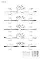
- FIGS. 2a and 2b are graphs each measuring coma aberration according to an exemplary embodiment of the present invention, where tangential aberration and sagittal aberration of each wavelength based on a field height are measured.
- a coma aberration correcting function is good as curves approach the X axis from a positive axis and a negative axis.
- coma aberration correction function demonstrates a superior figure.
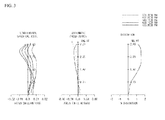
- FIG.3 is a graph illustrating an aberration according to an exemplary embodiment of the present invention.
- FIG.3 is a graph measuring longitudinal spherical aberration, astigmatic field curves and distortion in order from left side.
- a Y axis means size of an image
- an X axis means focal length (unit: mm) and distortion degree (unit: %).
- an aberration correcting function is good as curves approach the Y axis.
- spherical aberration, astigmatic aberration and distortion aberration all demonstrate a superior figure.
Landscapes
- Physics & Mathematics (AREA)
- General Physics & Mathematics (AREA)
- Optics & Photonics (AREA)
- Lenses (AREA)
Abstract
a third lens having negative (-) refractive power, a fourth lens having positive (+) refractive power, and a fifth lens having negative (-) refractive power, wherein the imaging lens meets a conditional expression of 0.8 < ∑T/((FLD)X2) < 1.2, where ∑T is a distance from an object side surface of the first lens to an image-forming surface, and FLD is a distance from an optical axis to a maximum image height.
Description
- The teachings in accordance with exemplary embodiments of this disclosure relate generally to an imaging lens.
- This section provides background information related to the present disclosure which is not necessarily prior art.
- Recently, vigorous research efforts are being made in the field of a mobile phone-purpose camera module, a digital still camera (DSC), a camcorder, and a PC camera (an imaging device attached to a person computer) all connected with an image pick-up system. One of the most important components in order that a camera module related to such image pickup system obtains an image is an imaging lens producing an image.
- Recently, there have been attempts to construct an imaging lens of high-resolution by using 5 pieces of lenses. Each of 5 pieces of lenses is comprised of lenses with a positive (+) refractive power and lenses with a negative (-) refractive power. For example, Korean Laid-open Patent Publication No.
2009-0048298 - An imaging lens of such a framework using 5 pieces of lenses must have satisfactory optic characteristics or aberration characteristics, and therefore an imaging lens with a high-resolution and a new power structure is required.
- This section provides a general summary of the disclosure, and is not a comprehensive disclosure of its full scope or all of its features.
- Accordingly, exemplary embodiments of the present disclosure may relate to an imaging lens that substantially obviates one or more of the above disadvantages/problems due to limitations and disadvantages of related art, and it is an object of the present disclosure to provide a miniaturized compact imaging lens configured to have a high resolution.
- Technical problems to be solved by the present disclosure are not restricted to the above-mentioned, and any other technical problems not mentioned so far will be clearly appreciated from the following description by skilled in the art.
- In one general aspect of the present disclosure, there is provided an imaging lens, the imaging lens comprising, in an ordered way from an object side,: a first lens having positive (+) refractive power; a second lens having negative (-) refractive power; a third lens having negative (-) refractive power; a fourth lens having positive (+) refractive power; and a fifth lens having negative (-) refractive power, wherein the imaging lens meets a conditional expression of 0.8 < ∑T/((FLD)X2) < 1.2, where ∑T is a distance from an object side surface of the first lens to an image-forming surface, and FLD is a distance from an optical axis to a maximum image height.
- Preferably, but not necessarily, the imaging lens may meet a conditional expression of 0.5 < f1/f < 1.5, where a focal length is f, and a focal length of the first lens is f1. Preferably, but not necessarily, the imaging lens may meet a conditional expression of 0.5 < ∑T/f < 1.5, where ∑T is a distance from an object side surface of the first lens to an image-forming surface, and a focal length is f.
- Preferably, but not necessarily, the imaging lens may meet a conditional expression of 1.6 < N2 < 1.7, where refractive index of the second lens is N2.
- Preferably, but not necessarily, the imaging lens may meet a conditional expression of 1.5 < N1 < 1.6, 1.5 < N3 < 1.6, 1.5 < N4 < 1.6, 1.5 < N5 < 1.6, where each refractive index of the first, third, fourth and fifth lens is respectively N1, N3, N4 and N5.
- Preferably, but not necessarily, the imaging lens may meet a conditional expression of 20 < V2 < 30, where Abbe's number of second lens is V2.
- Preferably, but not necessarily, the imaging lens may meet a conditional expression of 50 < V1 < 60, 50 < V3 < 60, 50 < V4 < 60, 50 < V5 < 60, where Abbe's number of each of the first, third, fourth and fifth lens is respectively V1, V3, V4 and V5.
- Preferably, but not necessarily, the imaging lens may meet a conditional expression of 0.6 < tanΘ < 0.8, where a half field angle of the maximum image height is tanΘ.
- Preferably, but not necessarily, all of the third, fourth and fifth lenses may be aspherical at both surfaces.
- Preferably, but not necessarily, the fourth lens may take a meniscus shape concavely formed at an object side surface.
- Preferably, but not necessarily, the fifth lens may take a meniscus shape convexly formed at an object side surface, and an object side surface and an image side surface may be all formed with inflection points.
- Preferably, but not necessarily, an object side surface and an image side surface of the third lens may be all formed with inflection points, and the third lens may have a smaller refractive power than that of other lenses.
- Preferably, but not necessarily, the imaging lens may meet a conditional expression of 0 < | 1/f3 | < 0.2, where a focal length of the third lens is f3.
- In another general aspect of the present disclosure, there is provided an imaging lens, the imaging lens comprising: in an ordered way from an object side,: a first lens having positive (+) refractive power; a second lens having negative (-) refractive power; a third lens having negative (-) refractive power; a fourth lens having positive (+) refractive power; and a fifth lens having negative (-) refractive power, wherein an object side surface and an image side surface of the third lens are all formed with inflection points.
- Preferably, but not necessarily, the third lens may have a smaller refractive power than that of the first, second, fourth and fifth lenses.
- Preferably, but not necessarily, the imaging lens may meet a conditional expression of 0.8 < ∑T/((FLD)X2) < 1.2, where ∑T is a distance from an object side surface of the first lens to an image-forming surface, and FLD is a distance from an optical axis to a maximum image height.
- Preferably, but not necessarily, the imaging lens may meet a conditional expression of 0.6 < tanΘ < 0.8, where a half field angle of the maximum image height is tanΘ.
- In still another general aspect of the present disclosure, there is provided an imaging lens, the imaging lens comprising: in an ordered way from an object side,: a first lens having positive (+) refractive power; a second lens having negative (-) refractivepower; a third lens having negative (-) refractive power; a fourth lens having positive (+) refractive power; and a fifth lens having negative (-) refractive power, wherein an object side surface and an image side surface of the fifth lens are all formed with inflection points.
- Preferably, but not necessarily, the imaging lens may meet a conditional expression of 0.8 < ∑T/((FLD)X2) < 1.2, where ∑T is a distance from an object side surface of the first lens to an image-forming surface, and FLD is a distance from an optical axis to a maximum image height.
- Preferably, but not necessarily, the third lens may have a smaller refractive power than that of the first, second, fourth and fifth lenses.
- The exemplary embodiments of the present disclosure have an advantageous effect in that the imaging lens is configured with 5 (five) pieces of lenses to have a high performance, a high resolution and a miniaturized construction.
-
-
FIG. 1 is a constructional view illustrating a camera module lens according to an exemplary embodiment of the present invention. -
FIGS. 2a and2b are graphs each measuring coma aberration according to an exemplary embodiment of the present invention. -
FIG.3 is a graph illustrating an aberration according to an exemplary embodiment of the present invention. - Exemplary embodiments of the present disclosure will be described in detail with reference to the accompanying drawings.
-
FIG. 1 is a constructional view illustrating a camera module lens according to an exemplary embodiment of the present invention. - The camera module lens according to an exemplary embodiment of the present invention is arranged with an imaging lens comprised of a plurality of lenses about an optical axis. In the constructional view of
FIG.1 , relative thickness, size and shape of a lens may be exaggerated or reduced for clarity and explanations throughout, and spherical or aspherical shape may be proposed as an example, and therefore the shape is not limited thereto. - Referring to
FIG. 1 , the camera lens module according to an exemplary embodiment of the present invention is arranged with, in an ordered way from an object side, a first lens (10), a second lens (20), a third lens (30), a fourth lens (40), a fifth lens (50), a filter (60) and a photo-detector (70). - Light corresponding to image information of a subject is incident on the photo-detector (70) by passing the first lens (10), the second lens (20), the third lens (30), the fourth lens (40), the fifth lens (50) and the filter (60).
- Hereinafter, in the description of the construction of each lens, an "object side surface" means a surface of a lens facing an object side with respect to an optical axis, and an "image side surface" means a surface of the lens facing a capturing surface with respect to the optical axis.
- The first lens (10) has a positive (+) refractive power, the second lens (20) has a negative (-) refractive power, the third lens (30) has a negative (-) refractive power, the fourth lens (40) has a positive (+) refractive power, and the fifth lens (50) has a negative (-) refractive power. At this time, the third, fourth and fifth lenses are aspherical at both surfaces. The fourth lens (40) takes a meniscus form concavely formed at an object side surface.
- The fifth lens (50) takes a meniscus shape convexly formed at an object side surface, and an object side surface and an image side surface are all formed with inflection points. An object side surface and an image side surface of the third lens (30) are all formed with inflection points, and the third lens (30) has a smaller refractive power than that of other lenses. Thus, an exemplary embodiment of the present disclosure can realize a high performance, a high resolution and a compact miniaturized imaging lens.
- For information, 'S1 and 'S2' of
FIG.1 are respectively an object side surface and an image side surface of the first lens (10), 'S3' and 'S4' are respectively an object side surface and an image side surface of the second lens(20), 'S5' and 'S6' are respectively an object side surface and an image side surface of the third lens(30), 'S7' and 'S8' are respectively an object side surface and an image side surface of the fourth lens(40), 'S9' and 'S10' are respectively an object side surface and an image side surface of the fifth lens(50), and 'S11' and 'S12' are respectively an object side surface and an image side surface of the filter (60). - The filter (60) may be any one optical filter selected from an infrared filter and a cover glass. The filter (60), if applied with the infrared filter, blocks radiant heat emitted from external light from being transferred to the photo-detector (70). Furthermore, the infrared filter transmits visible light, reflects infrared ray and outputs the reflected infrared ray to the outside.
- The photo-detector (70) is an image sensor, for example, CCD (Charge Coupled Device) or CMOS (Complementary Metal Oxide Semiconductor), etc.
- Because the later-described conditional expressions and exemplary embodiments are preferred embodiments enhancing an effect of interaction, it would be obvious to those skilled in the art that the present invention is not necessarily comprised of the following conditions. For example, only by satisfying some conditions of later-described conditional expressions, the lens construction (framework) of the present invention may have an enhanced effect of interaction.
- [Conditional expression 1] 0.5 < f1/f < 1.5
- [Conditional expression 2] 0.5 < ∑T/f < 1.5
- [Conditional expression 3] 1.6 < N2 < 1.7
- [Conditional expression 4] 1.5 < N1 < 1.6, 1.5 < N3 < 1.6, 1.5 < N4 < 1.6, 1.5 < N5 < 1.6
- [Conditional expression 5] 20 < V2 < 30
- [Conditional expression 6] 50 < V1 < 60, 50 < V3 < 60, 50 < V4 < 60, 50 < V5 < 60
- [Conditional expression 7] 0.8 < ∑T/((FLD)X2) < 1.2
- [Conditional expression 8] 0.6 < tanΘ < 0.8
- [Conditional expression 9] 0 < | 1/f3 | < 0.2,
-
Conditional expressions conditional expressions conditional expressions - Hereinafter, the action and effect of the present disclosure will be described with reference to a specific exemplary embodiment. Aspheric mentioned in a later- exemplary embodiment is obtained from a known
Equation 1, and 'E and its succeeding number' used in Conic constant k and aspheric coefficient A, B, C, D, E, F indicates 10's power. For example, E+01 denotes 101, and E-02 denotes 10-2.
where, z: a distance from the lens's top-point to an optical axis direction,
c: basic curvature of a lens , Y: a distance towards a direction perpendicular to an optical axis, K: Conic constant, and A, B, C, D, E, F: aspheric coefficients - The following Table 1 shows an exemplary embodiment matching the aforementioned conditional expressions.
[Table 1] Exemplary embodiment f 4.08 f1 2.62 f2 -4.07 f3 -851 f4 2.32 f5 -2.28 f1/f 0.64 ∑T 4.95 ∑T/f 1.21 N1 1.533 V1 56.5 N2 1.64 V2 23 N3,N4,N5 1.533 V3,V4,V5 56.5 tanΘ 0.71 FLD 2.93 - Referring to Table 1, it can be noted that f1/f is 0.64 that matches the
conditional expression 1, and ∑T/f is 1.21 that matches theconditional expression conditional expression 9. - The following Table 2 shows an exemplary embodiment which is a more detailed exemplary embodiment over that of Table 1.
[Table 2] Surface number Curvature radius (R) Thickness or distance (d) Refractive index (N) 1* 1.636 0.589 1.53 2* -8.522 0.06 3* 29.657 0.30 1.64 4* 2.409 0.432 5* 7.211 0.35 1.53 6* 6.9787 0.323 7* -2.604 0.733 1.53 8* -0.922 0.168 9* 7.432 0.5 1.53 10* 1.022 0.569 11 Infinity 0.3 1.52 12 Infinity 0.624 image Infinity 0.000 - The notation * in the above Table 2 and following Table 3, which is further written near the surface number indicates aspheric. The following Tables 3 and 4 show a value of aspheric coefficient of each lens in the exemplary embodiment of Table 2.
[Table 3] Surface number k A B C D E 1* 0 -0.278840E-01 -0.115063E-01 -0.314565E-02 0.436500E-02 -0.364702E-02 2* 0 -0.691104E-02 -0.212701E-01 0.124050E-01 -0.861190E-02 0.297906E-02 3* 0 -0.193793E-01 0.103822E-01 -0.133796E-02 -0.148393E-02 0.104056E-02 4* -4.310108 -0.198769E-01 0.309275E-01 -0.153250E-01 0.316803E -02 -0.164905E-04 5* 0 -0.508923E-01 0.134434E-01 -0.118161E-02 0 0 6* 0 -0.184261E-01 0.197696E-02 0.142627 E-03 0 0 7* -8.536520 -0.287370E-01 0.202006E-01 -0.841387E-02 0.244085E-02 -0.357293E-03 8* -1.771588 0.30330E-01 -0.176527E-01 0.367535E-02 0.161459E-03 -0.760293E-04 [Table 4] Surface number k AR4 AR5 AR6 AR7 AR8 9* -7.0056E+02 -1.2757E-01 1.1368E-02 4.1523E-02 -5.3501E-03 -1.2262E+02 AR9 AR10 AR11 AR12 AR13 AR14 4.4870E-04 2.8592E-03 4.8780E-04 -4.6489E-04 10* -6.8439E+00 -1.4989E-01 9.5116E-02 -1.6103E-02 -3.3468E-04 -4.3534E-03 AR9 AR10 AR11 AR12 AR13 AR14 9.3429E-04 8.5340E-04 -2.0891E-04 -2.1224E-05 -
FIGS. 2a and2b are graphs each measuring coma aberration according to an exemplary embodiment of the present invention, where tangential aberration and sagittal aberration of each wavelength based on a field height are measured. InFIGS.2a and2b , it is interpreted that a coma aberration correcting function is good as curves approach the X axis from a positive axis and a negative axis. In the measurement exemplary embodiments ofFIGS. 2a and2b , because values of images in nearly all fields proximate to the X axis, coma aberration correction function demonstrates a superior figure. - Furthermore,
FIG.3 is a graph illustrating an aberration according to an exemplary embodiment of the present invention. - That is,
FIG.3 is a graph measuring longitudinal spherical aberration, astigmatic field curves and distortion in order from left side. InFIG.3 , a Y axis means size of an image, and an X axis means focal length (unit: mm) and distortion degree (unit: %). InFIG.3 , it is interpreted that an aberration correcting function is good as curves approach the Y axis. In the shown aberration diagram, because values of images in nearly all fields appear proximate to the Y axis, spherical aberration, astigmatic aberration and distortion aberration all demonstrate a superior figure. - That is, a range of the longitudinal spherical aberration is -0.012mm ∼ +0.009mm, a range of astigmatic aberration is -0.035mm ∼ +0.017mm, and a range of distortion aberration is 0mm ∼ +1.5mm, such that the imaging lens according to the exemplary embodiments of the present invention can correct the characteristics of spherical aberration, astigmatic aberration and distortion aberration, whereby the imaging lens according to the exemplary embodiment of the present invention has an excellent lens characteristics.
- The previous description of the present invention is provided to enable any person skilled in the art to make or use the invention. Various modifications to the invention will be readily apparent to those skilled in the art, and the generic principles defined herein may be applied to other variations without departing from the spirit or scope of the invention. Thus, the invention is not intended to limit the examples described herein, but is to be accorded the widest scope consistent with the principles and novel features disclosed herein.
f1, f2, f3, f4, f5: a focus length of the first, second, third, fourth and fifth lens,
∑ T: a distance from an object side surface of the first lens to an image-forming surface,
tanΘ: a half field angle of the maximum image height is tanΘ,
N1, N2, N3, N4, N5: refractive index of first, second, third, fourth and fifth lens, and
V1, V2, V3, V4, V5: Abbe's numbers of the first to fifth lenses.
Claims (15)
- An imaging lens, the imaging lens comprising: in an ordered way from an object side, a first lens having positive (+) refractive power;
a second lens having negative (-) refractive power;
a third lens having negative (-) refractive power;
a fourth lens having positive (+) refractive power; and
a fifth lens having negative (-) refractive power, wherein the imaging lens meets a conditional expression of 0.8 < ∑T/((FLD)X2) < 1.2, where ∑T is a distance from an object side surface of the first lens to an image-forming surface, and FLD is a distance from an optical axis to a maximum image height. - The imaging lens of claim 1, meeting a conditional expression of 0.5 < f1/f < 1.5, where a focal length is f, and a focal length of the first lens is f1.
- The imaging lens of claim 1, meeting a conditional expression of 0.5 < ∑T/f < 1.5, where ∑T is a distance from an object side surface of the first lens to an image-forming surface, and a focal length is f.
- The imaging lens of claim 1, meeting a conditional expression of 1.6 < N2 < 1.7, where refractive index of the second lens is N2, or meeting a conditional expression of 1.5 < N1 < 1.6, 1.5 < N3 < 1.6, 1.5 < N4 < 1.6, 1.5 < N5 < 1.6, where each refractive index of the first, third, fourth and fifth lens is respectively N1, N3, N4 and N5.
- The imaging lens of claim 1, meeting a conditional expression of 20 < V2 < 30, where Abbe's number of second lens is V2, or meeting a conditional expression of 50 < V1 < 60, 50 < V3 < 60, 50 < V4 < 60, 50 < V5 < 60, where Abbe's number of each of the first, third, fourth and fifth lens is respectively V1, V3, V4 and V5.
- The imaging lens of claim 1, wherein all of the third, fourth and fifth lenses are aspherical at both surfaces.
- The imaging lens of claim 1, wherein the fourth lens takes a meniscus shape concavely formed at an object side surface.
- The imaging lens of claim 1,wherein the fifth lens takes a meniscus shape convexly formed at an object side surface, and an object side surface and an image side surface are all formed with inflection points.
- The imaging lens of claim 1, wherein an object side surface and an image side surface of the third lens are all formed with inflection points, and the third lens has a smaller refractive power than that of other lenses.
- The imaging lens of claim 1, meeting a conditional expression of 0 < | 1/f3 | < 0.2, where a focal length of the third lens is f3.
- An imaging lens, the imaging lens comprising: in an ordered way from an object side,
a first lens having positive (+) refractive power;
a second lens having negative (-) refractive power;
a third lens having negative (-) refractive power;
a fourth lens having positive (+) refractive power; and
a fifth lens having negative (-) refractive power, wherein an object side surface and an image side surface of the third lens are all formed with inflection points. - The imaging lens of claim 1 or claim 11, meeting a conditional expression of 0.6 < tanΘ < 0.8, where a half field angle of the maximum image height is tanΘ.
- An imaging lens, the imaging lens comprising: in an ordered way from an object side,
a first lens having positive (+) refractive power;
a second lens having negative (-) refractive power;
a third lens having negative (-) refractive power;
a fourth lens having positive (+) refractive power; and
a fifth lens having negative (-) refractive power, wherein an object side surface and an image side surface of the fifth lens are all formed with inflection points. - The imaging lens of claim 11 or claim 13, meeting a conditional expression of 0.8 < ∑T/((FLD)X2) < 1.2, where ∑T is a distance from an object side surface of the first lens to an image-forming surface, and FLD is a distance from an optical axis to a maximum image height.
- The imaging lens of claim 11 or claim 13, wherein the third lens has a smaller refractive power than that of the first, second, fourth and fifth lenses.
Applications Claiming Priority (1)
| Application Number | Priority Date | Filing Date | Title |
|---|---|---|---|
| KR1020120015698A KR101964297B1 (en) | 2012-02-16 | 2012-02-16 | Imaging lens |
Publications (1)
| Publication Number | Publication Date |
|---|---|
| EP2629131A1 true EP2629131A1 (en) | 2013-08-21 |
Family
ID=47722099
Family Applications (1)
| Application Number | Title | Priority Date | Filing Date |
|---|---|---|---|
| EP20130155067 Withdrawn EP2629131A1 (en) | 2012-02-16 | 2013-02-13 | Imaging lens |
Country Status (4)
| Country | Link |
|---|---|
| US (2) | US8958164B2 (en) |
| EP (1) | EP2629131A1 (en) |
| KR (1) | KR101964297B1 (en) |
| CN (1) | CN103257434B (en) |
Cited By (2)
| Publication number | Priority date | Publication date | Assignee | Title |
|---|---|---|---|---|
| EP3017326B1 (en) * | 2013-07-04 | 2021-01-06 | Corephotonics Ltd. | Miniature telephoto lens assembly |
| CN114167587A (en) * | 2021-12-29 | 2022-03-11 | 江西晶超光学有限公司 | Optical system, image capturing module and electronic equipment |
Families Citing this family (46)
| Publication number | Priority date | Publication date | Assignee | Title |
|---|---|---|---|---|
| KR101964297B1 (en) * | 2012-02-16 | 2019-04-01 | 엘지이노텍 주식회사 | Imaging lens |
| CN109194849B (en) | 2013-06-13 | 2021-01-15 | 核心光电有限公司 | Double-aperture zooming digital camera |
| US9857568B2 (en) | 2013-07-04 | 2018-01-02 | Corephotonics Ltd. | Miniature telephoto lens assembly |
| CN104007537B (en) * | 2014-01-27 | 2017-01-11 | 玉晶光电(厦门)有限公司 | Optical imaging lens and electronic device with optical imaging lens |
| CN104007536A (en) * | 2014-01-27 | 2014-08-27 | 玉晶光电(厦门)有限公司 | Portable electronic device and optical imaging lens thereof |
| US9392188B2 (en) | 2014-08-10 | 2016-07-12 | Corephotonics Ltd. | Zoom dual-aperture camera with folded lens |
| KR101710320B1 (en) * | 2014-11-18 | 2017-02-27 | 주식회사 코렌 | Photographic Lens Optical System |
| US10288840B2 (en) | 2015-01-03 | 2019-05-14 | Corephotonics Ltd | Miniature telephoto lens module and a camera utilizing such a lens module |
| TWI589916B (en) * | 2015-01-06 | 2017-07-01 | 先進光電科技股份有限公司 | Optical image capturing system |
| KR102369443B1 (en) * | 2016-12-29 | 2022-03-03 | 삼성전기주식회사 | Optical system and portable electronic device including the same |
| CN106646829B (en) | 2017-01-04 | 2018-08-14 | 浙江舜宇光学有限公司 | Telephoto lens and photographic device |
| US11347016B2 (en) | 2017-02-23 | 2022-05-31 | Corephotonics Ltd. | Folded camera lens designs |
| CN107193108B (en) | 2017-03-24 | 2019-10-15 | 玉晶光电(厦门)有限公司 | Optical imaging lens |
| KR20190022522A (en) | 2017-07-07 | 2019-03-06 | 코어포토닉스 리미티드 | Folding camera prism design to prevent stray light |
| EP4235249A3 (en) | 2017-07-23 | 2023-12-06 | Corephotonics Ltd. | Compact folded lenses with large apertures |
| CN107608057B (en) * | 2017-11-07 | 2023-12-01 | 浙江舜宇光学有限公司 | Image pickup lens group |
| KR102467648B1 (en) | 2018-03-02 | 2022-11-16 | 코어포토닉스 리미티드 | Spacer design to mitigate stray light |
| TWI644140B (en) * | 2018-05-11 | 2018-12-11 | 大立光電股份有限公司 | Optical imaging lens assembly, image capturing unit and electronic device |
| US12663617B2 (en) | 2018-05-14 | 2026-06-23 | Corephotonics Ltd. | Folded camera lens designs |
| CN114609756B (en) | 2018-05-14 | 2024-07-19 | 核心光电有限公司 | Lens assembly |
| EP4471485A3 (en) | 2019-01-03 | 2025-01-15 | Corephotonics Ltd. | Multi-aperture cameras with at least one two state zoom camera |
| KR102424008B1 (en) | 2019-02-25 | 2022-07-22 | 코어포토닉스 리미티드 | Multi-aperture camera with at least one two-state zoom camera |
| CN114578518B (en) | 2019-08-21 | 2025-01-21 | 核心光电有限公司 | Lens components |
| TWI795061B (en) * | 2019-08-30 | 2023-03-01 | 南韓商三星電機股份有限公司 | Optical imaging system |
| US12072609B2 (en) | 2019-09-24 | 2024-08-27 | Corephotonics Ltd. | Slim pop-out cameras and lenses for such cameras |
| US11656538B2 (en) | 2019-11-25 | 2023-05-23 | Corephotonics Ltd. | Folded zoom camera module with adaptive aperture |
| CN118158379A (en) | 2020-01-08 | 2024-06-07 | 核心光电有限公司 | Multi-hole zooming digital camera system |
| US12372742B2 (en) | 2020-05-15 | 2025-07-29 | Samsung Electronics Co., Ltd. | Wide-field imaging lens and optical image capturing device for electronic mobile devices |
| CN117518313A (en) | 2020-05-30 | 2024-02-06 | 核心光电有限公司 | System for obtaining super macro images |
| EP4014083A4 (en) | 2020-07-22 | 2022-09-21 | Corephotonics Ltd. | FOLDED CAMERA LENS MODELS |
| CN119376165A (en) | 2020-07-31 | 2025-01-28 | 核心光电有限公司 | camera |
| KR20220020015A (en) * | 2020-08-11 | 2022-02-18 | 엘지이노텍 주식회사 | Optical system |
| EP4127788A4 (en) | 2020-09-18 | 2024-06-19 | Corephotonics Ltd. | Pop-out zoom camera |
| US12271105B2 (en) | 2020-11-05 | 2025-04-08 | Corephotonics Ltd. | Scanning Tele camera based on two prism field of view scanning |
| CN114868065A (en) | 2020-12-01 | 2022-08-05 | 核心光电有限公司 | Folding camera with continuously adaptive zoom factor |
| CN117425062A (en) | 2021-01-25 | 2024-01-19 | 核心光电有限公司 | Lens systems for compact digital cameras |
| KR102723968B1 (en) | 2021-03-22 | 2024-10-29 | 코어포토닉스 리미티드 | Folded cameras with continuously adaptive zoom factor |
| US12228709B2 (en) | 2021-06-23 | 2025-02-18 | Corephotonics Ltd. | Compact folded tele cameras |
| KR102758730B1 (en) | 2021-09-23 | 2025-01-21 | 코어포토닉스 리미티드 | Large aperture continuous zoom folded tele cameras |
| CN119414560A (en) | 2021-11-02 | 2025-02-11 | 核心光电有限公司 | Camera module and mobile device |
| CN118541630B (en) | 2021-12-14 | 2025-06-13 | 核心光电有限公司 | Large aperture compact scan telephoto camera |
| KR20240124314A (en) | 2022-02-01 | 2024-08-16 | 코어포토닉스 리미티드 | Slim pop-out tele camera lens |
| US12348870B2 (en) | 2022-04-09 | 2025-07-01 | Corephotonics Ltd. | Spin-out 360-degree camera for smartphone |
| WO2024028811A1 (en) | 2022-08-05 | 2024-02-08 | Corephotonics Ltd. | Systems and methods for zoom digital camera with automatic adjustable zoom field of view |
| US12574642B1 (en) | 2022-10-19 | 2026-03-10 | Corephotonics Ltd. | Compact folded tele cameras |
| CN116931216A (en) * | 2023-09-01 | 2023-10-24 | 浙江舜宇光学有限公司 | Imaging system assembly |
Citations (4)
| Publication number | Priority date | Publication date | Assignee | Title |
|---|---|---|---|---|
| KR20090048298A (en) | 2007-11-08 | 2009-05-13 | 마이크롭틱스 주식회사 | Imaging lens |
| US20110013069A1 (en) * | 2009-07-14 | 2011-01-20 | Largan Precision Co., Ltd. | Imaging lens system |
| WO2011118554A1 (en) * | 2010-03-26 | 2011-09-29 | コニカミノルタオプト株式会社 | Imaging lens, imaging optical device, and digital equipment |
| CN202126531U (en) * | 2011-01-03 | 2012-01-25 | 大立光电股份有限公司 | Optical lens group for image capture |
Family Cites Families (11)
| Publication number | Priority date | Publication date | Assignee | Title |
|---|---|---|---|---|
| JP4650676B2 (en) * | 2005-03-03 | 2011-03-16 | ソニー株式会社 | Zoom lens and imaging device |
| JP4965199B2 (en) * | 2006-09-05 | 2012-07-04 | 富士フイルム株式会社 | Imaging lens |
| CN101470249B (en) * | 2007-12-25 | 2011-02-16 | 大立光电股份有限公司 | Four-piece type optical lens group for imaging |
| JP5201679B2 (en) * | 2008-12-25 | 2013-06-05 | 株式会社オプトロジック | Imaging lens |
| JP2012003077A (en) * | 2010-06-17 | 2012-01-05 | Olympus Imaging Corp | Imaging optical system and electronic imaging apparatus having the same |
| TWI418877B (en) * | 2010-12-15 | 2013-12-11 | Largan Precision Co | Imagery optical system |
| TWI429944B (en) * | 2011-01-07 | 2014-03-11 | Largan Precision Co | Image pickup optical lens assembly |
| JP5654384B2 (en) * | 2011-02-28 | 2015-01-14 | カンタツ株式会社 | Imaging lens |
| TWI429979B (en) * | 2011-04-13 | 2014-03-11 | Largan Precision Co Ltd | Optical image lens assembly |
| TWI447471B (en) * | 2011-05-24 | 2014-08-01 | Largan Precision Co Ltd | Image capturing lens assembly |
| KR101964297B1 (en) * | 2012-02-16 | 2019-04-01 | 엘지이노텍 주식회사 | Imaging lens |
-
2012
- 2012-02-16 KR KR1020120015698A patent/KR101964297B1/en active Active
-
2013
- 2013-02-06 US US13/760,343 patent/US8958164B2/en active Active
- 2013-02-13 EP EP20130155067 patent/EP2629131A1/en not_active Withdrawn
- 2013-02-18 CN CN201310052644.0A patent/CN103257434B/en active Active
-
2015
- 2015-01-14 US US14/597,021 patent/US9482846B2/en active Active
Patent Citations (6)
| Publication number | Priority date | Publication date | Assignee | Title |
|---|---|---|---|---|
| KR20090048298A (en) | 2007-11-08 | 2009-05-13 | 마이크롭틱스 주식회사 | Imaging lens |
| US20110013069A1 (en) * | 2009-07-14 | 2011-01-20 | Largan Precision Co., Ltd. | Imaging lens system |
| WO2011118554A1 (en) * | 2010-03-26 | 2011-09-29 | コニカミノルタオプト株式会社 | Imaging lens, imaging optical device, and digital equipment |
| US20130016278A1 (en) * | 2010-03-26 | 2013-01-17 | Keiji Matsusaka | Imaging Lens, Imaging Optical Device, and Digital Equipment |
| CN202126531U (en) * | 2011-01-03 | 2012-01-25 | 大立光电股份有限公司 | Optical lens group for image capture |
| US8179614B1 (en) * | 2011-01-03 | 2012-05-15 | Largan Precision Co. | Image pickup optical lens assembly |
Non-Patent Citations (1)
| Title |
|---|
| "Handbook of optical systems, Aberration theory and correction of optical systems", 1 January 2007, WILEY-VCH, Weinheim, DE, ISBN: 978-3-527-40379-0, article HERBERT GROSS ET AL: "Handbook of Optical Systems, Vol.3: Aberration Theory and Correction of Optical Systems", pages: 377 - 379, XP055258161 * |
Cited By (4)
| Publication number | Priority date | Publication date | Assignee | Title |
|---|---|---|---|---|
| EP3017326B1 (en) * | 2013-07-04 | 2021-01-06 | Corephotonics Ltd. | Miniature telephoto lens assembly |
| EP3017338B1 (en) * | 2013-07-04 | 2021-12-22 | Corephotonics Ltd. | Thin dual-aperture zoom digital camera |
| CN114167587A (en) * | 2021-12-29 | 2022-03-11 | 江西晶超光学有限公司 | Optical system, image capturing module and electronic equipment |
| CN114167587B (en) * | 2021-12-29 | 2023-11-24 | 江西晶超光学有限公司 | Optical systems, imaging modules and electronic equipment |
Also Published As
| Publication number | Publication date |
|---|---|
| CN103257434A (en) | 2013-08-21 |
| CN103257434B (en) | 2017-06-09 |
| KR20130094448A (en) | 2013-08-26 |
| KR101964297B1 (en) | 2019-04-01 |
| US20130215524A1 (en) | 2013-08-22 |
| US9482846B2 (en) | 2016-11-01 |
| US8958164B2 (en) | 2015-02-17 |
| US20150124335A1 (en) | 2015-05-07 |
Similar Documents
| Publication | Publication Date | Title |
|---|---|---|
| US9482846B2 (en) | Imaging lens | |
| KR101081187B1 (en) | Imaging Lens | |
| EP2718760B1 (en) | Imaging lens | |
| EP2725402B1 (en) | Imaging lens | |
| KR20110016152A (en) | Imaging lens | |
| KR20110071554A (en) | Imaging lens | |
| KR20110067548A (en) | Imaging lens | |
| KR20110024872A (en) | Lens module | |
| KR20100040357A (en) | Imaging lens | |
| US9658432B2 (en) | Imaging lens | |
| KR101933960B1 (en) | Imaging lens | |
| US20140340765A1 (en) | Optical image capturing system | |
| EP2761353B1 (en) | Imaging lens | |
| US9823440B2 (en) | Imaging lens | |
| KR101281368B1 (en) | Imaging lens | |
| KR102014454B1 (en) | Imaging lens | |
| KR20190035656A (en) | Imaging lens | |
| KR102292743B1 (en) | Imaging lens | |
| KR20100041385A (en) | Imaging lens | |
| KR20120137105A (en) | Imaging lens | |
| KR20150058122A (en) | Imaging Lens and Camera Moudule including the same |
Legal Events
| Date | Code | Title | Description |
|---|---|---|---|
| PUAI | Public reference made under article 153(3) epc to a published international application that has entered the european phase |
Free format text: ORIGINAL CODE: 0009012 |
|
| AK | Designated contracting states |
Kind code of ref document: A1 Designated state(s): AL AT BE BG CH CY CZ DE DK EE ES FI FR GB GR HR HU IE IS IT LI LT LU LV MC MK MT NL NO PL PT RO RS SE SI SK SM TR |
|
| AX | Request for extension of the european patent |
Extension state: BA ME |
|
| 17P | Request for examination filed |
Effective date: 20140212 |
|
| RBV | Designated contracting states (corrected) |
Designated state(s): AL AT BE BG CH CY CZ DE DK EE ES FI FR GB GR HR HU IE IS IT LI LT LU LV MC MK MT NL NO PL PT RO RS SE SI SK SM TR |
|
| RAP1 | Party data changed (applicant data changed or rights of an application transferred) |
Owner name: LG INNOTEK CO., LTD. |
|
| STAA | Information on the status of an ep patent application or granted ep patent |
Free format text: STATUS: EXAMINATION IS IN PROGRESS |
|
| 17Q | First examination report despatched |
Effective date: 20181015 |
|
| STAA | Information on the status of an ep patent application or granted ep patent |
Free format text: STATUS: THE APPLICATION IS DEEMED TO BE WITHDRAWN |
|
| 18D | Application deemed to be withdrawn |
Effective date: 20231010 |