EP2629006A1 - Light emitting diode and toy - Google Patents
Light emitting diode and toy Download PDFInfo
- Publication number
- EP2629006A1 EP2629006A1 EP13155463.6A EP13155463A EP2629006A1 EP 2629006 A1 EP2629006 A1 EP 2629006A1 EP 13155463 A EP13155463 A EP 13155463A EP 2629006 A1 EP2629006 A1 EP 2629006A1
- Authority
- EP
- European Patent Office
- Prior art keywords
- shell
- light emitting
- emitting diode
- toy
- eye
- Prior art date
- Legal status (The legal status is an assumption and is not a legal conclusion. Google has not performed a legal analysis and makes no representation as to the accuracy of the status listed.)
- Withdrawn
Links
- 210000001747 pupil Anatomy 0.000 claims description 8
- 230000008859 change Effects 0.000 claims description 6
- 210000001508 eye Anatomy 0.000 description 18
- 239000010410 layer Substances 0.000 description 10
- 239000000463 material Substances 0.000 description 8
- 239000004033 plastic Substances 0.000 description 6
- 239000004065 semiconductor Substances 0.000 description 6
- POIUWJQBRNEFGX-XAMSXPGMSA-N cathelicidin Chemical compound C([C@@H](C(=O)N[C@@H](CCCNC(N)=N)C(=O)N[C@@H](CCCCN)C(=O)N[C@@H](CO)C(=O)N[C@@H](CCCCN)C(=O)N[C@@H](CCC(O)=O)C(=O)N[C@@H](CCCCN)C(=O)N[C@@H]([C@@H](C)CC)C(=O)NCC(=O)N[C@@H](CCCCN)C(=O)N[C@@H](CCC(O)=O)C(=O)N[C@@H](CC=1C=CC=CC=1)C(=O)N[C@@H](CCCCN)C(=O)N[C@@H](CCCNC(N)=N)C(=O)N[C@@H]([C@@H](C)CC)C(=O)N[C@@H](C(C)C)C(=O)N[C@@H](CCC(N)=O)C(=O)N[C@@H](CCCNC(N)=N)C(=O)N[C@@H]([C@@H](C)CC)C(=O)N[C@@H](CCCCN)C(=O)N[C@@H](CC(O)=O)C(=O)N[C@@H](CC=1C=CC=CC=1)C(=O)N[C@@H](CC(C)C)C(=O)N[C@@H](CCCNC(N)=N)C(=O)N[C@@H](CC(N)=O)C(=O)N[C@@H](CC(C)C)C(=O)N[C@@H](C(C)C)C(=O)N1[C@@H](CCC1)C(=O)N[C@@H](CCCNC(N)=N)C(=O)N[C@@H]([C@@H](C)O)C(=O)N[C@@H](CCC(O)=O)C(=O)N[C@@H](CO)C(O)=O)NC(=O)[C@H](CC=1C=CC=CC=1)NC(=O)[C@H](CC(O)=O)NC(=O)CNC(=O)[C@H](CC(C)C)NC(=O)[C@@H](N)CC(C)C)C1=CC=CC=C1 POIUWJQBRNEFGX-XAMSXPGMSA-N 0.000 description 5
- 239000011248 coating agent Substances 0.000 description 3
- 238000000576 coating method Methods 0.000 description 3
- 230000000694 effects Effects 0.000 description 3
- 239000004593 Epoxy Substances 0.000 description 2
- 241000282326 Felis catus Species 0.000 description 2
- 230000008901 benefit Effects 0.000 description 2
- 238000010276 construction Methods 0.000 description 2
- 238000005286 illumination Methods 0.000 description 2
- 239000003973 paint Substances 0.000 description 2
- NIXOWILDQLNWCW-UHFFFAOYSA-N acrylic acid group Chemical group C(C=C)(=O)O NIXOWILDQLNWCW-UHFFFAOYSA-N 0.000 description 1
- 230000003213 activating effect Effects 0.000 description 1
- 239000000654 additive Substances 0.000 description 1
- 230000000996 additive effect Effects 0.000 description 1
- 239000000853 adhesive Substances 0.000 description 1
- 238000004026 adhesive bonding Methods 0.000 description 1
- 230000001070 adhesive effect Effects 0.000 description 1
- 210000005252 bulbus oculi Anatomy 0.000 description 1
- 210000003128 head Anatomy 0.000 description 1
- 239000012535 impurity Substances 0.000 description 1
- 238000004519 manufacturing process Methods 0.000 description 1
- 238000005259 measurement Methods 0.000 description 1
- 238000000034 method Methods 0.000 description 1
- 238000012986 modification Methods 0.000 description 1
- 230000004048 modification Effects 0.000 description 1
- 239000003607 modifier Substances 0.000 description 1
- 239000002991 molded plastic Substances 0.000 description 1
- 238000000465 moulding Methods 0.000 description 1
- 210000004279 orbit Anatomy 0.000 description 1
- 239000012044 organic layer Substances 0.000 description 1
- 238000004382 potting Methods 0.000 description 1
- 230000008569 process Effects 0.000 description 1
- 238000002310 reflectometry Methods 0.000 description 1
- 238000012360 testing method Methods 0.000 description 1
- 238000012546 transfer Methods 0.000 description 1
Images


Classifications
-
- F—MECHANICAL ENGINEERING; LIGHTING; HEATING; WEAPONS; BLASTING
- F21—LIGHTING
- F21V—FUNCTIONAL FEATURES OR DETAILS OF LIGHTING DEVICES OR SYSTEMS THEREOF; STRUCTURAL COMBINATIONS OF LIGHTING DEVICES WITH OTHER ARTICLES, NOT OTHERWISE PROVIDED FOR
- F21V9/00—Elements for modifying spectral properties, polarisation or intensity of the light emitted, e.g. filters
- F21V9/30—Elements containing photoluminescent material distinct from or spaced from the light source
-
- A—HUMAN NECESSITIES
- A63—SPORTS; GAMES; AMUSEMENTS
- A63H—TOYS, e.g. TOPS, DOLLS, HOOPS OR BUILDING BLOCKS
- A63H3/00—Dolls
- A63H3/36—Details; Accessories
- A63H3/38—Dolls' eyes
-
- F—MECHANICAL ENGINEERING; LIGHTING; HEATING; WEAPONS; BLASTING
- F21—LIGHTING
- F21V—FUNCTIONAL FEATURES OR DETAILS OF LIGHTING DEVICES OR SYSTEMS THEREOF; STRUCTURAL COMBINATIONS OF LIGHTING DEVICES WITH OTHER ARTICLES, NOT OTHERWISE PROVIDED FOR
- F21V33/00—Structural combinations of lighting devices with other articles, not otherwise provided for
- F21V33/008—Leisure, hobby or sport articles, e.g. toys, games or first-aid kits; Hand tools; Toolboxes
-
- F—MECHANICAL ENGINEERING; LIGHTING; HEATING; WEAPONS; BLASTING
- F21—LIGHTING
- F21V—FUNCTIONAL FEATURES OR DETAILS OF LIGHTING DEVICES OR SYSTEMS THEREOF; STRUCTURAL COMBINATIONS OF LIGHTING DEVICES WITH OTHER ARTICLES, NOT OTHERWISE PROVIDED FOR
- F21V9/00—Elements for modifying spectral properties, polarisation or intensity of the light emitted, e.g. filters
- F21V9/08—Elements for modifying spectral properties, polarisation or intensity of the light emitted, e.g. filters for producing coloured light, e.g. monochromatic; for reducing intensity of light
-
- F—MECHANICAL ENGINEERING; LIGHTING; HEATING; WEAPONS; BLASTING
- F21—LIGHTING
- F21Y—INDEXING SCHEME ASSOCIATED WITH SUBCLASSES F21K, F21L, F21S and F21V, RELATING TO THE FORM OR THE KIND OF THE LIGHT SOURCES OR OF THE COLOUR OF THE LIGHT EMITTED
- F21Y2115/00—Light-generating elements of semiconductor light sources
- F21Y2115/10—Light-emitting diodes [LED]
-
- H—ELECTRICITY
- H10—SEMICONDUCTOR DEVICES; ELECTRIC SOLID-STATE DEVICES NOT OTHERWISE PROVIDED FOR
- H10H—INORGANIC LIGHT-EMITTING SEMICONDUCTOR DEVICES HAVING POTENTIAL BARRIERS
- H10H20/00—Individual inorganic light-emitting semiconductor devices having potential barriers, e.g. light-emitting diodes [LED]
- H10H20/80—Constructional details
- H10H20/85—Packages
- H10H20/852—Encapsulations
- H10H20/854—Encapsulations characterised by their material, e.g. epoxy or silicone resins
Definitions
- LED light emitting diode
- lens for a LED
- LEDs Light emitting diodes
- LEDs have been used as a light source in part because of their relatively small size, low power/current requirements, long life, and variety of available output wavelengths, as well as compatibility with modem circuit construction.
- a light emitting diode for a toy includes a shell having a curved end.
- the curved end includes a colored translucent portion.
- a toy in another embodiment, includes a face having an eye.
- the eye includes a light emitting diode device arranged in the eye.
- a shell is disposed about the light emitting diode device and forming the exterior surface of the eye.
- the shell has a colored translucent portion.
- a toy figure having at least one eye.
- the toy includes a light emitting diode device disposed within the at least one eye.
- a shell is disposed about the light emitting diode device, the shell having an end portion forming an outer surface of the eye.
- a colored translucent portion coupled to the end portion and disposed to receive light from the light emitting diode device.
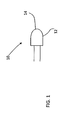
- FIG. 1 is a view of an LED
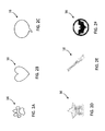
- FIGs. 2A-2F illustrates various configurations of shell or lens shapes in accordance with an embodiment of the present invention
- FIG. 3 illustrates a lens cap and lighting assembly in accordance with another embodiment of the present invention
- FIG. 4A-4B illustrates exemplary images produced by the embodiment illustrated in FIG. 3 ;
- FIG. 5 illustrates a lens cap and lighting assembly in accordance with yet another embodiment of the present invention
- FIG. 6 illustrates exemplary images produced by the embodiment illustrated in FIG. 5 ;
- FIG. 7 illustrates a side view of an LED device in accordance with another embodiment of the invention.
- FIG. 8 illustrates a top view of the LED device of FIG. 7 ;
- FIG. 9 illustrates a perspective view of a toy using the LED device of FIG. 7 .
- LED 10 is a semiconductor light source comprising a chip of semiconducting material doped with impurities to create a p-n junction.
- the semiconductor chip is typically potted in a shell 12.
- the shell 12 is molded out of a plastic material.
- the molded plastic shell 12 provides several functions one of which is to shape the light emission from the semiconductor by acting as a diffusing lens thereby allowing light to be emitted at a higher angle of incidence.
- an end portion 14 of the plastic shell has a curved surface.
- shell 12 and end portion 14 is configured to have a unique shape 16 corresponding to a desired feature.
- Non-limiting examples of such shapes are illustrated in FIGs. 2A-2F for example, a paw print, a heart, a star, a paintbrush, an insignia and a test balloon.
- FIGs. 2A-2F for example, a paw print, a heart, a star, a paintbrush, an insignia and a test balloon.
- numerous other configurations and/or shapes are considered to be within the scope of exemplary embodiments of the present invention. Accordingly and when illuminated by the LED, the unique shape represented by reconfigured shell 12 is also illuminated and may be projected to a certain distance from the end of the shell 12.
- the material comprising shell 12 e.g., plastic or any other equivalent material
- the material comprising shell 12 can be molded with a desired color or alternatively be clear and the LED itself provides the desired color.
- the reconfigured shell 12 adds esthetic value to the LED at little or no cost.
- the end portion 14 includes a decal, sticker, paint, adhesive or other tacky and/or opaque layer on the end portion 14.
- the opaque layer includes the unique shape 16.
- the unique shape 16 blocks emission of light in a pattern corresponding to the unique shape 16 such that a shadow of the shape appears within the LED's area of illumination.
- FIGS. 2 - 4 another embodiment of the present invention is illustrated.
- a lens cap or sleeve 18 is provided.
- the lens cap or sleeve 18 has a graphical image 20 disposed on either an interior surface 21 or exterior surface 23 of the lens cap 19.
- the lens cap or sleeve 18 is configured to be positioned over LED 10 and when the lens cap is placed over the LED 10 at a first focal length with respect to the LED 10, the graphical image 20 is projected on a surface 22.
- the lens cap 18 is movably mounted with respect to the LED 10 such that the lens cap 20 can be moved in the directions of arrows 24 (e.g., inwardly and outwardly with respect to the LED) to change the effect and focus of the image 20 being projected.
- the lens cap or sleeve 18 will change the appearance of image 20 being projected.
- the lens cap 18 is provided with multiple images 20 each being provided at different locations and/or having different focal lengths with respect to the LED 10 such that as the lens cap 18 moves in the directions of arrows 24 with respect to LED 10 different images may be generated or come into and out of focus as the lens cap 18 is moved in the directions of arrows 24 with respect to LED 10.
- an image projection system 26 is provided.
- projection of the image is desired to be approximately 6 centimeters from the lens cap or sleeve 18. It should be appreciated that distances greater or less than the aforementioned 6 cm are considered to be within the scope of exemplary embodiments of the present invention.
- the lens cap or sleeve 18 is provided with a lenticular lens 30 such that depending on the location of the lens cap or sleeve 18 with respect to the LED 10 and/or the position of an observer with respect to the projection system 26 different graphical images 20 or combinations thereof are provided. Accordingly and in this embodiment, the lens cap or sleeve 18 has multiple graphical images 20 disposed on either an interior or exterior surface of the lens cap that are projected or magnified through the use of a lenticular lens 30. Similar to the embodiment of FIGS.
- the lens cap or sleeve 18 is configured to be positioned over LED 10 and when the lens cap is placed over the LED 10, at least one of the graphical images 20 is projected on a surface or viewable upon a surface of the lens cap or sleeve 18.
- the lens cap or sleeve 18 is movably mounted with respect to the LED 10 such that the lens cap or sleeve 18 can be moved in the directions of arrows 24 (e.g., inwardly and outwardly with respect to the LED 10) to change the effect and focus of the image 20 and/or the image 20 being projected.
- the LED 40 is configured in the shape and appearance of an eye for a toy, such as a cat's eye for example.
- the LED 40 includes a shell 42 having a substantially cylindrical portion 44 and a curved end portion 46.
- the shell 42 is a molded member made from a suitable plastic material such as acrylic for example.
- the shell 42 may be manufactured from an epoxy.
- an LED device 48 Arranged within the shell 42 is an LED device 48 that generates light when current or voltage is applied to the leads 50, 52.
- the LED device 48 may include a semiconductor die and a lead frame comprising an anvil and a post.
- the semiconductor die may rest within a reflective cavity and be electrically connected to the anvil and post, which may serve as a cathode and an anode (e.g. leads 50, 52) for the LED device 48, respectively.
- the LED device 48 may include driver circuitry such as a ballast resistor or other electrical components as is known in the art.
- the LED 40 is sized and shaped to be used in a toy figure 60, such as a doll, for example, to represent a physical feature of the toy 60 such as an eye.
- the LED 40 includes an iris portion 54 and a pupil portion 56.
- the iris portion 54 comprises a tinted translucent or semi translucent layer potted within the shell 42.
- the translucent layer may include a thin colored plastic that is curved to match the interior curvature of the curved end portion 46.
- the potted translucent layer passes light generated by the LED device 48 through the curved end portion 46 of the LED 40.
- the pupil portion 56 may be opaque such that light generated by the LED device 48, is blocked from exiting the curved end portion 46 of the LED 40 through that portion.
- the pupil portion 56 includes a layer of dye or ink potted or embedded within the LED 40.
- the dye or ink may be printed, stamped, or otherwise affixed to the translucent layer that forms the iris portion 54.
- a circular portion 58 is disposed about the iris portion 54.
- the circular portion 58 may be opaque or translucent.
- the circular portion 58 is translucent and a different color than the iris portion 54.
- the circular portion 58 may serve to further distinguish the iris portion 54 from the remainder of the LED 40. Additional light generated by the LED device 48 may exit the LED 40 through other portions of the LED 40, such as the cylindrical portion 44 of the LED 40.
- the net effect of activating the exemplary LED 40 is to simulate an eye where the iris and the "white" of the eye glow. Potting or manufacturing a tinted layer within the LED 40, as opposed to on the external surface of the LED, may allow for a more realistic look to the eye. The thin epoxy layer between the tinted layer and the external surface of the LED 40 may more accurately simulate the look and reflectivity from the organic layer of moisture on a real eyeball.
- the iris 54 and a pupil 56 may be formed via a coating applied to the surface of the curved portion 46.
- the coating may be but is not limited to a paint, a gel-coat, and ink or other suitable material, for example.
- the coating may include phosphors that change the color of the light being emitted from the LED 40.
- the translucent iris portion 54 may be a colored additive material that is integrated with the plastic material during the molding process.
- the iris portion 54 or the pupil portion 56 may be a separately formed component that is coupled to the exterior of the shell 42, such as by adhesive bonding, for example.
- the LED 40 may be used in a toy figure 60, such as on a face of the toy 60 to simulate an eye, for example.
- the LED 40 may be embedded within an eye socket of the toy figure 60.
- the curved portion 46 may form the exterior portion of the eye visible to the user. When the LED is illuminated, the light will transfer through the shell 42 and the iris portion 54, while being blocked or partially blocked by the opaque pupil portion 56.
- the LED 40 may be electrically coupled to electronics, such as a processor and a power source, within the head and/or torso of the toy figure 60.
- the LED 40 may be controlled by the processor. For example, the level of illumination from the LED 40 may be controlled to provide the appearance of a cat's eye collecting and reflecting low levels of ambient light in near-dark conditions.
- the processor may control the LED 40 using pulse-width modulation in order to simulate a "twinkle" in the eye.
- the terms “first,” “second,” and the like, herein do not denote any order, quantity, or importance, but rather are used to distinguish one element from another, and the terms “a” and “an” herein do not denote a limitation of quantity, but rather denote the presence of at least one of the referenced item.
- the terms “bottom” and “top” are used herein, unless otherwise noted, merely for convenience of description, and are not limited to any one position or spatial orientation.
Landscapes
- Engineering & Computer Science (AREA)
- General Engineering & Computer Science (AREA)
- Physics & Mathematics (AREA)
- Spectroscopy & Molecular Physics (AREA)
- Toys (AREA)
Abstract
A light emitting diode (40) is provided to be used as a body part, such as an eye, for a toy. The light emitting diode includes a light emitting diode device (48) arranged in the eye. A shell (42) is disposed about the light emitting diode device and forming the exterior surface of the eye. A colored translucent portion (54) is arranged to form the iris of the eye and receive light from the light emitting device.
Description
- The present Application claims the benefit of United States Provisional Application Serial No.
61/713,077 filed on 12 October 2012 61/600,332 filed on 17 February 2012 - Various embodiments disclosed herein are related to a light emitting diode (LED), and more particularly a lens for a LED.
- Light emitting diodes (LEDs) have been used as a light source in part because of their relatively small size, low power/current requirements, long life, and variety of available output wavelengths, as well as compatibility with modem circuit construction.
- Accordingly, it is desirable to provide a light emitting diode with a lens or cover that expands upon existing uses.
- In one embodiment, a light emitting diode for a toy is provided. The light emitting diode includes a shell having a curved end. The curved end includes a colored translucent portion.
- In another embodiment, a toy is provided. The toy includes a face having an eye. The eye includes a light emitting diode device arranged in the eye. A shell is disposed about the light emitting diode device and forming the exterior surface of the eye. The shell has a colored translucent portion.
- In yet another embodiment, a toy figure is provided having at least one eye. The toy includes a light emitting diode device disposed within the at least one eye. A shell is disposed about the light emitting diode device, the shell having an end portion forming an outer surface of the eye. A colored translucent portion coupled to the end portion and disposed to receive light from the light emitting diode device.
- These and/or other features, aspects, and advantages of the present invention will become better understood when the following detailed description is read with reference to the accompanying drawings in which like characters represent like parts throughout the drawings, wherein:
-
FIG. 1 is a view of an LED; -
FIGs. 2A-2F illustrates various configurations of shell or lens shapes in accordance with an embodiment of the present invention; -
FIG. 3 illustrates a lens cap and lighting assembly in accordance with another embodiment of the present invention; -
FIG. 4A-4B illustrates exemplary images produced by the embodiment illustrated inFIG. 3 ; -
FIG. 5 illustrates a lens cap and lighting assembly in accordance with yet another embodiment of the present invention; -
FIG. 6 illustrates exemplary images produced by the embodiment illustrated inFIG. 5 ; -
FIG. 7 illustrates a side view of an LED device in accordance with another embodiment of the invention; -
FIG. 8 illustrates a top view of the LED device ofFIG. 7 ; and -
FIG. 9 illustrates a perspective view of a toy using the LED device ofFIG. 7 . - Although the drawings represent varied embodiments and features of the present invention, the drawings are not necessarily to scale and certain features may be exaggerated in order to illustrate and explain exemplary embodiments the present invention. The exemplification set forth herein illustrates several aspects of the invention, in one form, and such exemplification is not to be construed as limiting the scope of the invention in any manner.
- Referring now to the attached FIGS., a light emitting diode (LED) 10 is illustrated. As is known the
related arts LED 10 is a semiconductor light source comprising a chip of semiconducting material doped with impurities to create a p-n junction. The semiconductor chip is typically potted in ashell 12. In one implementation, theshell 12 is molded out of a plastic material. The moldedplastic shell 12 provides several functions one of which is to shape the light emission from the semiconductor by acting as a diffusing lens thereby allowing light to be emitted at a higher angle of incidence. - In a typical construction, an
end portion 14 of the plastic shell has a curved surface. In accordance with one non-limiting embodiment of the present invention,shell 12 andend portion 14 is configured to have aunique shape 16 corresponding to a desired feature. Non-limiting examples of such shapes are illustrated inFIGs. 2A-2F for example, a paw print, a heart, a star, a paintbrush, an insignia and a test balloon. Of course, numerous other configurations and/or shapes are considered to be within the scope of exemplary embodiments of the present invention. Accordingly and when illuminated by the LED, the unique shape represented by reconfiguredshell 12 is also illuminated and may be projected to a certain distance from the end of theshell 12. Furthermore, the material comprising shell 12 (e.g., plastic or any other equivalent material) can be molded with a desired color or alternatively be clear and the LED itself provides the desired color. As may be appreciated, the reconfiguredshell 12 adds esthetic value to the LED at little or no cost. - In alternative embodiments, the
end portion 14 includes a decal, sticker, paint, adhesive or other tacky and/or opaque layer on theend portion 14. The opaque layer includes theunique shape 16. Theunique shape 16 blocks emission of light in a pattern corresponding to theunique shape 16 such that a shadow of the shape appears within the LED's area of illumination. - Referring now to
FIGS. 2 - 4 , another embodiment of the present invention is illustrated. Here a lens cap orsleeve 18 is provided. In this embodiment, the lens cap orsleeve 18 has agraphical image 20 disposed on either aninterior surface 21 orexterior surface 23 of thelens cap 19. The lens cap orsleeve 18 is configured to be positioned overLED 10 and when the lens cap is placed over theLED 10 at a first focal length with respect to theLED 10, thegraphical image 20 is projected on asurface 22. Still further and in one embodiment, thelens cap 18 is movably mounted with respect to theLED 10 such that thelens cap 20 can be moved in the directions of arrows 24 (e.g., inwardly and outwardly with respect to the LED) to change the effect and focus of theimage 20 being projected. In other words and depending upon the focal point of theimage 20, movement of the lens cap orsleeve 18 will change the appearance ofimage 20 being projected. - In yet another implementation, the
lens cap 18 is provided withmultiple images 20 each being provided at different locations and/or having different focal lengths with respect to theLED 10 such that as thelens cap 18 moves in the directions ofarrows 24 with respect toLED 10 different images may be generated or come into and out of focus as thelens cap 18 is moved in the directions ofarrows 24 with respect toLED 10. - Accordingly and through the combination of
LED 10 andlens cap 18, animage projection system 26 is provided. In one embodiment, projection of the image is desired to be approximately 6 centimeters from the lens cap orsleeve 18. It should be appreciated that distances greater or less than the aforementioned 6 cm are considered to be within the scope of exemplary embodiments of the present invention. - Referring now to
FIGS. 5 and 6 , another alternative embodiment of the present invention is illustrated. Here the lens cap orsleeve 18 is provided with alenticular lens 30 such that depending on the location of the lens cap orsleeve 18 with respect to theLED 10 and/or the position of an observer with respect to theprojection system 26 differentgraphical images 20 or combinations thereof are provided. Accordingly and in this embodiment, the lens cap orsleeve 18 has multiplegraphical images 20 disposed on either an interior or exterior surface of the lens cap that are projected or magnified through the use of alenticular lens 30. Similar to the embodiment ofFIGS. 3 and 4 , the lens cap orsleeve 18 is configured to be positioned overLED 10 and when the lens cap is placed over theLED 10, at least one of thegraphical images 20 is projected on a surface or viewable upon a surface of the lens cap orsleeve 18. As previously mentioned, the lens cap orsleeve 18 is movably mounted with respect to theLED 10 such that the lens cap orsleeve 18 can be moved in the directions of arrows 24 (e.g., inwardly and outwardly with respect to the LED 10) to change the effect and focus of theimage 20 and/or theimage 20 being projected. - Referring now
FIG.7-FIG.9 , anotherexemplary LED 40 is shown where theLED 40 is configured in the shape and appearance of an eye for a toy, such as a cat's eye for example. In this embodiment, theLED 40 includes ashell 42 having a substantiallycylindrical portion 44 and acurved end portion 46. Theshell 42 is a molded member made from a suitable plastic material such as acrylic for example. In alternative embodiments, theshell 42 may be manufactured from an epoxy. Arranged within theshell 42 is anLED device 48 that generates light when current or voltage is applied to theleads LED device 48 may include a semiconductor die and a lead frame comprising an anvil and a post. The semiconductor die may rest within a reflective cavity and be electrically connected to the anvil and post, which may serve as a cathode and an anode (e.g. leads 50, 52) for theLED device 48, respectively. It should be appreciated that theLED device 48 may include driver circuitry such as a ballast resistor or other electrical components as is known in the art. - The
LED 40 is sized and shaped to be used in a toy figure 60, such as a doll, for example, to represent a physical feature of thetoy 60 such as an eye. To simulate the look of an eye, theLED 40 includes aniris portion 54 and apupil portion 56. In one exemplary embodiment, theiris portion 54 comprises a tinted translucent or semi translucent layer potted within theshell 42. The translucent layer may include a thin colored plastic that is curved to match the interior curvature of thecurved end portion 46. The potted translucent layer passes light generated by theLED device 48 through thecurved end portion 46 of theLED 40. Thepupil portion 56 may be opaque such that light generated by theLED device 48, is blocked from exiting thecurved end portion 46 of theLED 40 through that portion. In some embodiments, thepupil portion 56 includes a layer of dye or ink potted or embedded within theLED 40. The dye or ink may be printed, stamped, or otherwise affixed to the translucent layer that forms theiris portion 54. In some embodiments, acircular portion 58 is disposed about theiris portion 54. Thecircular portion 58 may be opaque or translucent. In one embodiment, thecircular portion 58 is translucent and a different color than theiris portion 54. Thecircular portion 58 may serve to further distinguish theiris portion 54 from the remainder of theLED 40. Additional light generated by theLED device 48 may exit theLED 40 through other portions of theLED 40, such as thecylindrical portion 44 of theLED 40. The net effect of activating theexemplary LED 40 is to simulate an eye where the iris and the "white" of the eye glow. Potting or manufacturing a tinted layer within theLED 40, as opposed to on the external surface of the LED, may allow for a more realistic look to the eye. The thin epoxy layer between the tinted layer and the external surface of theLED 40 may more accurately simulate the look and reflectivity from the organic layer of moisture on a real eyeball. - In other embodiments, the
iris 54 and apupil 56 may be formed via a coating applied to the surface of thecurved portion 46. The coating may be but is not limited to a paint, a gel-coat, and ink or other suitable material, for example. In one embodiment the coating may include phosphors that change the color of the light being emitted from theLED 40. In other embodiments thetranslucent iris portion 54 may be a colored additive material that is integrated with the plastic material during the molding process. In still other embodiments, theiris portion 54 or thepupil portion 56 may be a separately formed component that is coupled to the exterior of theshell 42, such as by adhesive bonding, for example. - The
LED 40 may be used in a toy figure 60, such as on a face of thetoy 60 to simulate an eye, for example. TheLED 40 may be embedded within an eye socket of the toy figure 60. Thecurved portion 46 may form the exterior portion of the eye visible to the user. When the LED is illuminated, the light will transfer through theshell 42 and theiris portion 54, while being blocked or partially blocked by theopaque pupil portion 56. TheLED 40 may be electrically coupled to electronics, such as a processor and a power source, within the head and/or torso of the toy figure 60. TheLED 40 may be controlled by the processor. For example, the level of illumination from theLED 40 may be controlled to provide the appearance of a cat's eye collecting and reflecting low levels of ambient light in near-dark conditions. In other embodiments, the processor may control theLED 40 using pulse-width modulation in order to simulate a "twinkle" in the eye. - As used herein, the terms "first," "second," and the like, herein do not denote any order, quantity, or importance, but rather are used to distinguish one element from another, and the terms "a" and "an" herein do not denote a limitation of quantity, but rather denote the presence of at least one of the referenced item. In addition, it is noted that the terms "bottom" and "top" are used herein, unless otherwise noted, merely for convenience of description, and are not limited to any one position or spatial orientation.
- The modifier "about" used in connection with a quantity is inclusive of the stated value and has the meaning dictated by the context (e.g., includes the degree of error associated with measurement of the particular quantity).
- While the invention has been described with reference to an exemplary embodiment, it will be understood by those skilled in the art that various changes may be made and equivalents may be substituted for elements thereof without departing from the scope of the invention. In addition, many modifications may be made to adapt a particular situation or material to the teachings of the invention without departing from the essential scope thereof. Therefore, it is intended that the invention not be limited to the particular embodiment disclosed as the best mode contemplated for carrying out this invention, but that the invention will include all embodiments falling within the scope of the appended claims.
Claims (14)
- A light emitting diode for a toy, comprising:a shell having a curved end;a colored translucent portion having a predetermined shape operably coupled to the curved end; anda light generating portion disposed within the shell, the light generating portion configured to direct light towards the translucent portion.
- The light emitting diode as in claim 1, wherein the shell is formed in the shape of an eye and the translucent portion is embedded within the shell and forms an iris portion of the eye.
- The light emitting diode as in claim 2 further comprising an opaque portion on the curved end that forms a pupil portion of the eye.
- The light emitting diode as in claim 1, further comprising a sleeve movably disposed over the shell, the translucent portion being operably coupled to the sleeve on an end opposite the light generating portion.
- The light emitting diode as in claim 1 wherein the translucent portion is formed from a gel-coat.
- The light emitting diode as in claim 3 wherein the translucent portion includes phosphors configured to change the color of the light passing through the translucent portion.
- A toy comprising:a face having an eye;a light emitting diode device arranged in the eye;a shell disposed about the light emitting diode device and forming the exterior surface of the eye; anda colored translucent portion operably coupled to the shell.
- The toy of claim 7, wherein the translucent portion is formed from a layer embedded within the shell.
- The toy of claim 8 wherein the translucent portion includes phosphors configured to change the color of light received from the light emitting diode device.
- The toy as in claim 9 further comprising an opaque portion centrally positioned on the translucent portion.
- The toy of claim 10 wherein the opaque portion forms a pupil of the eye.
- The toy of claim 7 further comprising a sleeve disposed a least partially over the shell, the translucent portion being operably coupled to the sleeve..
- The toy of claim 12 further comprising a lens cap disposed on an end of the sleeve opposite the shell.
- The toy of claim 13 wherein the translucent portion is disposed on a surface of the lens cap.
Applications Claiming Priority (2)
| Application Number | Priority Date | Filing Date | Title |
|---|---|---|---|
| US201261600332P | 2012-02-17 | 2012-02-17 | |
| US201261713077P | 2012-10-12 | 2012-10-12 |
Publications (1)
| Publication Number | Publication Date |
|---|---|
| EP2629006A1 true EP2629006A1 (en) | 2013-08-21 |
Family
ID=47912893
Family Applications (1)
| Application Number | Title | Priority Date | Filing Date |
|---|---|---|---|
| EP13155463.6A Withdrawn EP2629006A1 (en) | 2012-02-17 | 2013-02-15 | Light emitting diode and toy |
Country Status (3)
| Country | Link |
|---|---|
| US (1) | US20130217300A1 (en) |
| EP (1) | EP2629006A1 (en) |
| CN (1) | CN103256557A (en) |
Families Citing this family (4)
| Publication number | Priority date | Publication date | Assignee | Title |
|---|---|---|---|---|
| US10360859B1 (en) * | 2016-03-23 | 2019-07-23 | Valerie J. Heilbron | Eye animation device and method to show eye expression in 2D and 3D lighted displays |
| JP2018061718A (en) * | 2016-10-13 | 2018-04-19 | トヨタ自動車株式会社 | Communication device |
| JP2019101492A (en) * | 2017-11-28 | 2019-06-24 | トヨタ自動車株式会社 | Communication apparatus |
| US12157067B2 (en) | 2023-01-16 | 2024-12-03 | Nicholas Black | Durable programmable illuminated replica eye and a method of making the same |
Citations (10)
| Publication number | Priority date | Publication date | Assignee | Title |
|---|---|---|---|---|
| US5004443A (en) * | 1990-01-22 | 1991-04-02 | Michael Su | Electronic eyeball of doll |
| DE4302572A1 (en) * | 1993-01-29 | 1994-08-04 | Scharrer & Koch Sigikid | Eye operating arrangement for eg. teddy bear |
| EP1279426A2 (en) * | 2001-07-27 | 2003-01-29 | Annemarie Schellmann | Toy object in the shape of a reproduction of a living creature |
| FR2849212A1 (en) * | 2002-12-24 | 2004-06-25 | Patrice Annic | Device for reproducing optical illusion of eye in statue comprises convergent hemispherical lens with plane rear face and colored zone in center representing iris, rear face lit by fiber optic bundle |
| US20060169998A1 (en) * | 2005-02-02 | 2006-08-03 | Gelcore, Llc | Red line emitting phosphor materials for use in LED applications |
| US20080285257A1 (en) * | 2007-05-18 | 2008-11-20 | King Kristopher C | Audio speaker illumination system |
| US20090318057A1 (en) * | 2008-06-18 | 2009-12-24 | Hong Fu Jin Precision Industry (Shenzhen) Co., Ltd. | Toy eye |
| US20100105279A1 (en) * | 2008-10-27 | 2010-04-29 | Hong Fu Jin Precision Industry (Shenzhen) Co., Ltd | Simulative eye for toy |
| US20100136880A1 (en) * | 2008-12-01 | 2010-06-03 | Hong Fu Jin Precision Industry (Shenzhen) Co., Ltd | Replica eye |
| DE102011001928A1 (en) * | 2011-04-08 | 2012-10-11 | Lumitech Produktion Und Entwicklung Gmbh | Color conversion element and lamp |
Family Cites Families (10)
| Publication number | Priority date | Publication date | Assignee | Title |
|---|---|---|---|---|
| US3232004A (en) * | 1963-01-15 | 1966-02-01 | Felsher William | Electrical flashing and sounding toys |
| US5314336A (en) * | 1992-02-07 | 1994-05-24 | Mark Diamond | Toy and method providing audio output representative of message optically sensed by the toy |
| US5672090A (en) * | 1995-11-22 | 1997-09-30 | Lcd International L.L.C. | Equine-shaped toy figure |
| US6048209A (en) * | 1998-05-26 | 2000-04-11 | Bailey; William V. | Doll simulating adaptive infant behavior |
| US7566142B2 (en) * | 2004-02-13 | 2009-07-28 | Jam Strait, Inc. | Changing color LEDS |
| WO2005029163A1 (en) * | 2003-09-17 | 2005-03-31 | Segan Industries, Inc. | Flash imaging devices, methods for making and using the same |
| US8052502B2 (en) * | 2004-11-17 | 2011-11-08 | Sally Lee Connolly | Illuminated artificial eye structures for toys, mannequins and the like |
| US7566258B2 (en) * | 2004-11-17 | 2009-07-28 | Sally Lee Connolly | Interactive plush toy |
| US7611396B2 (en) * | 2007-02-27 | 2009-11-03 | Disney Enterprises, Inc. | Illuminated balloon with an externally mounted, rear projector |
| US8647167B2 (en) * | 2009-08-20 | 2014-02-11 | Valerie J. Heilbron | Lighted display devices for producing static or animated visual displays, including animated facial features |
-
2013
- 2013-02-15 US US13/768,338 patent/US20130217300A1/en not_active Abandoned
- 2013-02-15 EP EP13155463.6A patent/EP2629006A1/en not_active Withdrawn
- 2013-02-17 CN CN2013100520251A patent/CN103256557A/en active Pending
Patent Citations (10)
| Publication number | Priority date | Publication date | Assignee | Title |
|---|---|---|---|---|
| US5004443A (en) * | 1990-01-22 | 1991-04-02 | Michael Su | Electronic eyeball of doll |
| DE4302572A1 (en) * | 1993-01-29 | 1994-08-04 | Scharrer & Koch Sigikid | Eye operating arrangement for eg. teddy bear |
| EP1279426A2 (en) * | 2001-07-27 | 2003-01-29 | Annemarie Schellmann | Toy object in the shape of a reproduction of a living creature |
| FR2849212A1 (en) * | 2002-12-24 | 2004-06-25 | Patrice Annic | Device for reproducing optical illusion of eye in statue comprises convergent hemispherical lens with plane rear face and colored zone in center representing iris, rear face lit by fiber optic bundle |
| US20060169998A1 (en) * | 2005-02-02 | 2006-08-03 | Gelcore, Llc | Red line emitting phosphor materials for use in LED applications |
| US20080285257A1 (en) * | 2007-05-18 | 2008-11-20 | King Kristopher C | Audio speaker illumination system |
| US20090318057A1 (en) * | 2008-06-18 | 2009-12-24 | Hong Fu Jin Precision Industry (Shenzhen) Co., Ltd. | Toy eye |
| US20100105279A1 (en) * | 2008-10-27 | 2010-04-29 | Hong Fu Jin Precision Industry (Shenzhen) Co., Ltd | Simulative eye for toy |
| US20100136880A1 (en) * | 2008-12-01 | 2010-06-03 | Hong Fu Jin Precision Industry (Shenzhen) Co., Ltd | Replica eye |
| DE102011001928A1 (en) * | 2011-04-08 | 2012-10-11 | Lumitech Produktion Und Entwicklung Gmbh | Color conversion element and lamp |
Also Published As
| Publication number | Publication date |
|---|---|
| CN103256557A (en) | 2013-08-21 |
| US20130217300A1 (en) | 2013-08-22 |
Similar Documents
| Publication | Publication Date | Title |
|---|---|---|
| KR100649540B1 (en) | Safety indicator light bulb | |
| US7086756B2 (en) | Lighting element using electronically activated light emitting elements and method of making same | |
| US5882110A (en) | Elongated, decorative, flexible, light-transmitting assembly | |
| EP2629006A1 (en) | Light emitting diode and toy | |
| US8496346B2 (en) | Illuminated novelty topper | |
| EP1618540A2 (en) | Lighted balloons | |
| CN104415542A (en) | Illuminated doll | |
| US4646208A (en) | Vehicle top mark | |
| US6145999A (en) | Battery device | |
| US7232251B2 (en) | Night light with fiber optics | |
| US20180202620A1 (en) | Lighted animals | |
| KR101712734B1 (en) | Breathable gaiters secured | |
| JPS58196067A (en) | Luminous body with light emitting diode as light source | |
| US20130301138A1 (en) | Marking board with back-focusing and brightness enhancement effect | |
| US9476553B2 (en) | Flashing night light | |
| US20170184281A1 (en) | Conformal coated lighting or lumination system | |
| US20130258298A1 (en) | LED image projection apparatus | |
| US9295308B2 (en) | Animated display badge | |
| CN201391798Y (en) | Luminous strip structure with free shaping ability | |
| KR200203917Y1 (en) | Detachable luminous eyes | |
| KR200454032Y1 (en) | LED-Fiber Optic Interlocking Luminescent Umbrella with Child Protection | |
| KR200467624Y1 (en) | Device for providing luminous printing image | |
| CN222010544U (en) | 3D vision residual fan | |
| CN221463669U (en) | Light-emitting assembly | |
| TWM361596U (en) | Illumination strip capable of freely shaping |
Legal Events
| Date | Code | Title | Description |
|---|---|---|---|
| PUAI | Public reference made under article 153(3) epc to a published international application that has entered the european phase |
Free format text: ORIGINAL CODE: 0009012 |
|
| AK | Designated contracting states |
Kind code of ref document: A1 Designated state(s): AL AT BE BG CH CY CZ DE DK EE ES FI FR GB GR HR HU IE IS IT LI LT LU LV MC MK MT NL NO PL PT RO RS SE SI SK SM TR |
|
| AX | Request for extension of the european patent |
Extension state: BA ME |
|
| STAA | Information on the status of an ep patent application or granted ep patent |
Free format text: STATUS: THE APPLICATION IS DEEMED TO BE WITHDRAWN |
|
| 18D | Application deemed to be withdrawn |
Effective date: 20140222 |