EP2628934A2 - Thermoelectric generator in turbine engine nozzles - Google Patents
Thermoelectric generator in turbine engine nozzles Download PDFInfo
- Publication number
- EP2628934A2 EP2628934A2 EP13155543.5A EP13155543A EP2628934A2 EP 2628934 A2 EP2628934 A2 EP 2628934A2 EP 13155543 A EP13155543 A EP 13155543A EP 2628934 A2 EP2628934 A2 EP 2628934A2
- Authority
- EP
- European Patent Office
- Prior art keywords
- core
- plenum
- thermoelectric generator
- nozzle
- fan
- Prior art date
- Legal status (The legal status is an assumption and is not a legal conclusion. Google has not performed a legal analysis and makes no representation as to the accuracy of the status listed.)
- Granted
Links
Images





Classifications
-
- F—MECHANICAL ENGINEERING; LIGHTING; HEATING; WEAPONS; BLASTING
- F02—COMBUSTION ENGINES; HOT-GAS OR COMBUSTION-PRODUCT ENGINE PLANTS
- F02C—GAS-TURBINE PLANTS; AIR INTAKES FOR JET-PROPULSION PLANTS; CONTROLLING FUEL SUPPLY IN AIR-BREATHING JET-PROPULSION PLANTS
- F02C6/00—Plural gas-turbine plants; Combinations of gas-turbine plants with other apparatus; Adaptations of gas-turbine plants for special use
- F02C6/18—Plural gas-turbine plants; Combinations of gas-turbine plants with other apparatus; Adaptations of gas-turbine plants for special use using the waste heat of gas-turbine plants outside the plants themselves, e.g. gas-turbine power heat plants
-
- F—MECHANICAL ENGINEERING; LIGHTING; HEATING; WEAPONS; BLASTING
- F01—MACHINES OR ENGINES IN GENERAL; ENGINE PLANTS IN GENERAL; STEAM ENGINES
- F01D—NON-POSITIVE DISPLACEMENT MACHINES OR ENGINES, e.g. STEAM TURBINES
- F01D15/00—Adaptations of machines or engines for special use; Combinations of engines with devices driven thereby
- F01D15/10—Adaptations for driving, or combinations with, electric generators
-
- F—MECHANICAL ENGINEERING; LIGHTING; HEATING; WEAPONS; BLASTING
- F02—COMBUSTION ENGINES; HOT-GAS OR COMBUSTION-PRODUCT ENGINE PLANTS
- F02C—GAS-TURBINE PLANTS; AIR INTAKES FOR JET-PROPULSION PLANTS; CONTROLLING FUEL SUPPLY IN AIR-BREATHING JET-PROPULSION PLANTS
- F02C6/00—Plural gas-turbine plants; Combinations of gas-turbine plants with other apparatus; Adaptations of gas-turbine plants for special use
- F02C6/04—Gas-turbine plants providing heated or pressurised working fluid for other apparatus, e.g. without mechanical power output
-
- F—MECHANICAL ENGINEERING; LIGHTING; HEATING; WEAPONS; BLASTING
- F02—COMBUSTION ENGINES; HOT-GAS OR COMBUSTION-PRODUCT ENGINE PLANTS
- F02K—JET-PROPULSION PLANTS
- F02K1/00—Plants characterised by the form or arrangement of the jet pipe or nozzle; Jet pipes or nozzles peculiar thereto
-
- F—MECHANICAL ENGINEERING; LIGHTING; HEATING; WEAPONS; BLASTING
- F02—COMBUSTION ENGINES; HOT-GAS OR COMBUSTION-PRODUCT ENGINE PLANTS
- F02K—JET-PROPULSION PLANTS
- F02K1/00—Plants characterised by the form or arrangement of the jet pipe or nozzle; Jet pipes or nozzles peculiar thereto
- F02K1/78—Other construction of jet pipes
- F02K1/82—Jet pipe walls, e.g. liners
-
- F—MECHANICAL ENGINEERING; LIGHTING; HEATING; WEAPONS; BLASTING
- F02—COMBUSTION ENGINES; HOT-GAS OR COMBUSTION-PRODUCT ENGINE PLANTS
- F02K—JET-PROPULSION PLANTS
- F02K3/00—Plants including a gas turbine driving a compressor or a ducted fan
- F02K3/02—Plants including a gas turbine driving a compressor or a ducted fan in which part of the working fluid by-passes the turbine and combustion chamber
- F02K3/04—Plants including a gas turbine driving a compressor or a ducted fan in which part of the working fluid by-passes the turbine and combustion chamber the plant including ducted fans, i.e. fans with high volume, low pressure outputs, for augmenting the jet thrust, e.g. of double-flow type
- F02K3/06—Plants including a gas turbine driving a compressor or a ducted fan in which part of the working fluid by-passes the turbine and combustion chamber the plant including ducted fans, i.e. fans with high volume, low pressure outputs, for augmenting the jet thrust, e.g. of double-flow type with front fan
-
- H—ELECTRICITY
- H10—SEMICONDUCTOR DEVICES; ELECTRIC SOLID-STATE DEVICES NOT OTHERWISE PROVIDED FOR
- H10N—ELECTRIC SOLID-STATE DEVICES NOT OTHERWISE PROVIDED FOR
- H10N10/00—Thermoelectric devices comprising a junction of dissimilar materials, i.e. devices exhibiting Seebeck or Peltier effects
- H10N10/10—Thermoelectric devices comprising a junction of dissimilar materials, i.e. devices exhibiting Seebeck or Peltier effects operating with only the Peltier or Seebeck effects
- H10N10/13—Thermoelectric devices comprising a junction of dissimilar materials, i.e. devices exhibiting Seebeck or Peltier effects operating with only the Peltier or Seebeck effects characterised by the heat-exchanging means at the junction
-
- F—MECHANICAL ENGINEERING; LIGHTING; HEATING; WEAPONS; BLASTING
- F02—COMBUSTION ENGINES; HOT-GAS OR COMBUSTION-PRODUCT ENGINE PLANTS
- F02C—GAS-TURBINE PLANTS; AIR INTAKES FOR JET-PROPULSION PLANTS; CONTROLLING FUEL SUPPLY IN AIR-BREATHING JET-PROPULSION PLANTS
- F02C7/00—Features, components parts, details or accessories, not provided for in, or of interest apart form groups F02C1/00 - F02C6/00; Air intakes for jet-propulsion plants
- F02C7/32—Arrangement, mounting, or driving, of auxiliaries
-
- F—MECHANICAL ENGINEERING; LIGHTING; HEATING; WEAPONS; BLASTING
- F05—INDEXING SCHEMES RELATING TO ENGINES OR PUMPS IN VARIOUS SUBCLASSES OF CLASSES F01-F04
- F05D—INDEXING SCHEME FOR ASPECTS RELATING TO NON-POSITIVE-DISPLACEMENT MACHINES OR ENGINES, GAS-TURBINES OR JET-PROPULSION PLANTS
- F05D2220/00—Application
- F05D2220/70—Application in combination with
- F05D2220/76—Application in combination with an electrical generator
-
- Y—GENERAL TAGGING OF NEW TECHNOLOGICAL DEVELOPMENTS; GENERAL TAGGING OF CROSS-SECTIONAL TECHNOLOGIES SPANNING OVER SEVERAL SECTIONS OF THE IPC; TECHNICAL SUBJECTS COVERED BY FORMER USPC CROSS-REFERENCE ART COLLECTIONS [XRACs] AND DIGESTS
- Y02—TECHNOLOGIES OR APPLICATIONS FOR MITIGATION OR ADAPTATION AGAINST CLIMATE CHANGE
- Y02T—CLIMATE CHANGE MITIGATION TECHNOLOGIES RELATED TO TRANSPORTATION
- Y02T50/00—Aeronautics or air transport
- Y02T50/50—On board measures aiming to increase energy efficiency
-
- Y—GENERAL TAGGING OF NEW TECHNOLOGICAL DEVELOPMENTS; GENERAL TAGGING OF CROSS-SECTIONAL TECHNOLOGIES SPANNING OVER SEVERAL SECTIONS OF THE IPC; TECHNICAL SUBJECTS COVERED BY FORMER USPC CROSS-REFERENCE ART COLLECTIONS [XRACs] AND DIGESTS
- Y02—TECHNOLOGIES OR APPLICATIONS FOR MITIGATION OR ADAPTATION AGAINST CLIMATE CHANGE
- Y02T—CLIMATE CHANGE MITIGATION TECHNOLOGIES RELATED TO TRANSPORTATION
- Y02T50/00—Aeronautics or air transport
- Y02T50/60—Efficient propulsion technologies, e.g. for aircraft
Definitions
- the subject matter described herein relates to gas turbine engines, and more particularly to nozzle configurations for gas turbine engines.
- thermoelectric generator is a device that can generate electricity when a temperature differential is applied across the device.
- a TEG device is typically square or rectangular with the upper and lower end-caps having the same dimension and typically power generated by TEGs is transmitted via a set of power wires.
- TEG devices are typically thin (e.g., in the order of a couple of millimeters thick), small (e.g., a couple of square centimeters), flat, and brittle. Accordingly, TEG devices can be difficult to handle individually, especially for applications in vehicles, such as automobiles, aircraft and the like. Additionally, these devices can be subject to harsh enviromnental conditions, such as vibration, constant temperature variations and other harsh conditions.
- TEG devices Because of their size and the fact that each TEG device generates only a small amount of power, many TEG devices are bundled together in order to generate a useful amount of power. Further, TEG devices generally provide greater energy conversion efficiency at high temperature differentials. This can cause relatively large thermal expansion in materials. Because of thermal gradients and different thermal coefficients of expansion associated with different materials, thermally induced stresses may result.
- Efficiency of TEG devices generally increases with greater temperature differentials, i.e., the delta temperature between two opposite sides, typically called the heat source (hot side) and heat sink (cold side) of the TEG device. Also, energy conversion efficiency is maximized for any installation that channels heat flow through the TEG devices only without any thermal energy leaks through the surrounding structural material or gaps.
- gas turbine engine configurations are provided.
- gas turbine engines may be adapted to incorporate one or more thermoelectric generator assemblies to generate electricity from heat differentials in the gas turbine engine.
- a portion of the gas stream from the core may be diverted into a plenum where it flows across a first surface of a thermoelectric generator assembly.
- a portion of the air stream from the fan may be diverted into the plenum where it flows across a second surface of the thermoelectric generator assembly.
- the thermoelectric generator assembly generates electricity in response to a temperature differential between the gas stream from the core and the air stream from the fan.
- a core nozzle for a gas turbine engine comprising a core nozzle wall defining a core through which a core stream flows, a cowling assembly coupled to the core nozzle wall, wherein the core nozzle wall and the cowling assembly define a plenum to receive a portion of the core stream flow from the core nozzle, and a thermoelectric generator assembly positioned in the plenum.
- the assembly comprises an engine assembly, a core nozzle positioned adjacent the engine assembly to direct a core flow generated by the engine assembly, a fan nozzle surrounding at least a portion of the core nozzle to direct a fan flow wherein the core nozzle defines a plenum to receive a portion of the core stream flow from the core nozzle, and a thermoelectric generator assembly positioned in the plenum.
- a method to generate electricity in a gas turbine engine comprising generating a core stream flow in the gas turbine engine, redirecting a portion of the core stream flow from a core nozzle positioned downstream of the gas turbine engine into a plenum defined by the core nozzle, and passing the portion of the core stream flow redirected into the plenum over a first surface of a thermoelectric generator assembly.
- a core nozzle for a gas turbine engine comprising: a core nozzle wall defining a core through which a core stream flows; and a cowling assembly coupled to the core nozzle wall, wherein the core nozzle wall and the cowling assembly define a plenum to receive a portion of the core stream flow from the core nozzle; and a thermoelectric generator assembly positioned in the plenum.
- the core nozzle further comprises: a first heat transfer fin positioned in the plenum to transfer heat from a portion of the core stream flow from the core nozzle to the thermoelectric generator assembly; a second heat transfer fin positioned in the plenum to transfer heat from the thermoelectric generator assembly to a portion of a fan stream flow from a fan nozzle; wherein: the first heat transfer fin comprises at least one of a surface inlet or a scoop inlet; and the second heat transfer fin comprises at least one of a surface inlet or a scoop inlet; wherein: the thermoelectric generator assembly has a first surface positioned adjacent to the core stream flow and a second surface positioned adjacent the fan stream flow; wherein the thermoelectric generator assembly comprises at least one of peaked three-dimensional surfaces or corrugated three-dimensional surfaces; and wherein the thermoelectric generator assembly comprises: a frame; a plurality thermoelectric generator devices mounted on the frame; and a power bus to transport energy generated by the thermoelectric generator devices.
- a gas turbine engine assembly comprising: an engine assembly; a core nozzle positioned adjacent the engine assembly to direct a core stream flow generated by the engine assembly; a fan nozzle surrounding at least a portion of the core nozzle to direct a fan stream flow; wherein the core nozzle defines a plenum to receive a portion of the core stream flow from the core nozzle; and a thermoelectric generator assembly positioned in the plenum.
- the gas turbine engine assembly further comprises: a first heat transfer fin positioned in the plenum to transfer heat from a portion of the core stream flow from the core nozzle to the thermoelectric generator assembly; a second heat transfer fin positioned in the plenum to transfer heat from the thermoelectric generator assembly to a portion of the fan stream flow from the fan nozzle; wherein: the first heat transfer fin comprises at least one of a surface inlet or a scoop inlet; and the second heat transfer fin comprises at least one of a surface inlet or a scoop inlet; wherein: the thermoelectric generator assembly has a first surface positioned adjacent to the core stream flow and a second surface positioned adjacent the fan stream flow; wherein the thermoelectric generator assembly comprises at least one of peaked three-dimensional surfaces or corrugated three-dimensional surfaces; wherein the thermoelectric generator assembly comprises: a frame; a plurality thermoelectric generator devices mounted on the frame; and a power bus to transport energy generated by the thermoelectric generator devices.
- a method to generate electricity in a gas turbine engine comprising: generating a core stream flow in the gas turbine engine; redirecting a portion of the core stream flow from a core nozzle positioned downstream of the gas turbine engine into a plenum defined by the core nozzle; and passing the portion of the core stream flow redirected into the plenum over a first surface of a thermoelectric generator assembly.
- the method further comprises: generating a fan stream flow; redirecting a portion of the fan stream flow from a fan nozzle into the plenum defined by the core nozzle; and passing the portion of the fan stream flow redirected into the plenum over a second surface of a thermoelectric generator assembly; wherein the plenum is defined by core nozzle wall and cowling assembly of the core nozzle, and wherein one or more heat transfer fins transfer heat in the plenum; wherein airflow velocity in the plenum is different than airflow velocity in the core stream; and further comprising ejecting the portion of the core stream flow redirected into the plenum from the plenum into the fan stream flow; transporting electricity from the thermoelectric generator assembly on a power bus.
- a gas turbine engine core nozzle comprises a housing which defines a plenum.
- One or more thermoelectric generator devices may be disposed in the plenum. A portion of the gas flow from the engine core is diverted into the plenum, where it flows across a first surface of the thermoelectric generator to create a temperature differential across the thermoelectric generator.
- a portion of the fan stream may be directed into the plenum, where it flows across a second surface of the thermoelectric generator. Electricity generated by the thermoelectric generator may be transported via a power bus.
- thermoelectric generators may be implemented in gas turbine aircraft engines.
- Most common modem aircraft jet engines are either turbojet engines or turbofan engines.
- a turbojet engine air is drawn into the engine through an inlet by a compressor, compressed, mixed with fuel, and burned to produce a high temperature and pressure gas stream. Part of the energy in the high pressure gas is extracted by a turbine to run a compressor and to provide power for aircraft systems. After the turbine stage, high pressure gas is accelerated by a nozzle and exhausted to the atmosphere to produce thrust.
- This part of the engine is commonly referred to as the core or gas generator of the engine.
- the physical passage for the core gas flow is commonly referred to as the core duct and the external hardware to the core duct is known as the core cowling.
- the nozzle for the hot core exhaust stream is known as the core nozzle.
- a portion of the air flow down stream of the inlet is bypassed around the core and compressed by rotating blades.
- This air stream is not mixed with fuel and burned therefore is only slightly warmer than the atmosphere due to the energy addition from the blades.
- the high pressure air is then accelerated through a fan nozzle to produce thrust.
- This part of the engine is commonly referred to as the fan.
- the physical passage for the fan flow is commonly referred to as the fan duct and the external hardware to the fan duct is commonly referred to as the fan cowling.
- the nozzle for the cold fan exhaust stream is commonly referred to as the fan nozzle.
- Thrust produced by each stream is determined by the engine design and by the ratio of air mass flow in the bypass or fan stream to the core stream, sometimes referred to as the bypass ratio of the engine.
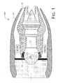
- Figs. 1-3 are schematic cross-sectional illustrations of gas turbine engine configurations into which thermoelectric generators may be installed, according to embodiments.
- a gas turbine engine configuration comprises an engine 110, a fan 112, a core nozzle 120 extending downstream from the engine and a fan nozzle 130 surrounding at least a portion of the core nozzle 120.
- the engine 110 creates a core flow of gas which is expelled via the core nozzle 120.
- the engine 110 also drives a fan 112, the blades 114 of which compress the bypassed flow of air referred to as the fan flow through the fan nozzle 130.
- Figs. 2 and 3 are schematic cross-sectional illustrations of gas turbine engine configurations similar to the configuration depicted in Fig. 1 .
- the primary difference between the embodiments depicted in Figs. 1-3 concerns the length of the fan nozzle 130 relative to the core nozzle 120.
- the fan nozzle 130 terminates at a point just short of the termination of core nozzle 120.
- the fan nozzle 130 terminates at a point well short of the termination of the core nozzle 120, such that the fan flow and the core flow are expelled in separate streams.
- the fan nozzle 130 terminates behind the termination of the core nozzle 120.
- the core nozzle 120 is adapted to define a plenum in which a thermoelectric generator assembly may be mounted.
- a thermoelectric generator assembly may be mounted.
- the core nozzle 120 comprises a core nozzle wall 122 defining a core through which a core stream flows.
- the core nozzle further comprises a cowling assembly 124 coupled to the core nozzle wall 120. Together, the core nozzle wall 122 and the cowling assembly 124 define a plenum 140 to receive a portion of the core stream flow from the core nozzle 120.
- a first heat transfer fin 142 is positioned in the plenum to transfer heat from a portion of the core stream flow from the core nozzle 120 to the thermoelectric generator assembly 150.
- a second heat transfer fin 144 may be positioned in the plenum to transfer heat from the thermoelectric generator assembly 150 to a portion of the fan stream flow from the fan nozzle 130.
- a scoop inlet 148 which is an inlet with an opening, or a scoop, that is placed into the flow stream with the opening facing the oncoming flow.
- a scoop inlet 148 is an inlet with an opening, or a scoop, that is placed into the flow stream with the opening facing the oncoming flow.
- thermoelectric generator assembly 150 is positioned in the plenum 140.
- the thermoelectric generator assembly 150 has a first surface 152 positioned adjacent to the core stream flow and a second surface 154 positioned adjacent the fan stream flow. Gas in the plenum 140 is expelled into the fan stream in the fan nozzle 130, such that the propulsive value of the gas is captured.
- the plenum 140 may define a sufficiently large volume such the airflow velocity in the plenum 140 may be different than airflow velocity in the core stream.
- the heat from the core flow gas creates a temperature differential across the thermoelectric generator assembly 150, which in turn causes the thermoelectric generator assembly 150 to generate an electrical current.
- thermoelectric generator assembly 150 may be constructed substantially in accordance with one or more of the embodiments described in commonly assigned and copending U.S. Patent Publication No. 2011/0108080 to Kwok, et al. , entitled Thermoelectric Generator Assembly and System, and U.S. Patent Publication No. 2009/0159110 to Kwok, et al. , entitled Thermoelectric Generation System.
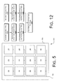
- Fig. 5 is a simplified schematic illustration of a thermoelectric generator assembly 150 suitable for use herein.
- a thermoelectric generator assembly 150 comprises a frame 156, a plurality thermoelectric generator devices 158 mounted on the frame, and a power bus 160 to transport the energy generated by the thermoelectric generator devices.
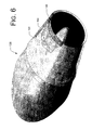
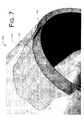
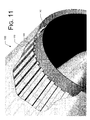
- Figs. 6-11 are schematic, perspective views of thermoelectric generator assemblies installed on gas turbine engines, according to embodiments.
- the fan nozzle is cut away to show the core nozzle 120, a portion of the thermoelectric generator assembly 150 disposed in the plenum 140.
- the plenum 140 may extend along a substantial portion of the length of the core nozzle 120.
- a plurality of frames 156 of thermoelectric generator assembly 150 may be disposed in the plenum 140 to generate electricity as described above.
- Figs. 8-9 illustrate a second embodiment in which the frames are arranged in the plenum 140 to define a peaked three-dimensional surface.
- Figs. 10-11 illustrate a second embodiment in which the TEG frames are arranged in the plenum 140 to define a corrugated three-dimensional surface.
- Fig. 12 is a flowchart illustrating operations in a method to generate electricity in a gas turbine engine, according to embodiments.
- a core stream flow is generated and at operation 1215 a fan stream flow is generated.
- operations 1210 and 1215 may be implemented by a gas turbine engine such as, e.g., a jet engine, when the engine is activated.
- a portion of the core stream flow is redirected from the core nozzle through the plenum, e.g., by using a heat transfer fin 142 as described above.
- a portion of the fan stream flow is redirected through the plenum, e.g., by using a heat transfer fin 144 as described above.
- thermoelectric generator assembly 150 produces electricity from the temperature differential between the first surface and the second surface of the thermoelectric generator assembly 150.
- the streams are expelled from the plenum into the fan stream.
- Fig. 13 is a schematic illustration of an aircraft 1300 having a nozzle configured according to embodiments.
- an aircraft 1300 comprises wings 1302, a fuselage 1301, and a propulsion system 1304.
- the illustrated propulsion system 1304 comprises at least one gas turbine engine, which may be implemented as a turbofan engine carried by the wings 1302.
- One or more of the propulsion systems 1304 may be embodied as described above to include one or more thermoelectic generator assemblies 150.
- gas turbine engine assemblies which bleed off a small portion of the core gas flow to generate electricity.
- overall performance for the engine may be reduced. But when heat energy is extracted from the core stream and put back into the fan stream, as in the embodiments described herein, engine performance does not suffer. In fact, overall engine performance may be increased. This is the reason why a turbofan outperfonns a turbojet in efficiency.
- energy is extracted from the hot gas in the engine core by a turbine. Through a mechanical shaft, the turbine drives a fan to move air in the fan stream. Energy in the fan stream increases by the energy extracted by the turbine from the core stream minus the system mechanical inefficiency. Propulsive efficiency for the fan is higher than that for the core. Therefore overall performance increases.
- thermoelectric generator assembly 150 As described herein, in some embodiments a relative small amount of hot gas in the core stream is bled off at the core nozzle wall. A portion of the heat energy in the hot gas is extracted and diverted through the thermoelectric generator assembly 150. Electric power is generated by the thermoelectric generator assembly 150. Remaining heat energy flow through the thermoelectric generator assembly 150 is cooled by a stream of cold fan air which is also bled similarly at core cowling. The now warmer cooling air is returned back to the fan stream prior to the fan nozzle exit. The amount of energy that is used to generate power is the product of the energy extracted into the TEG and the efficiency of the thermoelectric generator assembly 150, i.e.
- thermoelectric generator assembly 150 energy used to power generation is twenty percent of the energy extracted and flow into the thermoelectric generator assembly 150; eighty percent of the unused extracted energy is put into the fan stream by the cooling air and returned back within the control volume of the engine.
Landscapes
- Engineering & Computer Science (AREA)
- Mechanical Engineering (AREA)
- General Engineering & Computer Science (AREA)
- Chemical & Material Sciences (AREA)
- Combustion & Propulsion (AREA)
- Structures Of Non-Positive Displacement Pumps (AREA)
- Turbine Rotor Nozzle Sealing (AREA)
Abstract
wherein the core nozzle defines a plenum to receive a portion of the core stream flow from the core nozzle and a thermoelectric generator assembly positioned in the plenum. Other embodiments may be described.
Description
- The subject matter described herein relates to gas turbine engines, and more particularly to nozzle configurations for gas turbine engines.
- A thermoelectric generator (TEG) is a device that can generate electricity when a temperature differential is applied across the device. A TEG device is typically square or rectangular with the upper and lower end-caps having the same dimension and typically power generated by TEGs is transmitted via a set of power wires. TEG devices are typically thin (e.g., in the order of a couple of millimeters thick), small (e.g., a couple of square centimeters), flat, and brittle. Accordingly, TEG devices can be difficult to handle individually, especially for applications in vehicles, such as automobiles, aircraft and the like. Additionally, these devices can be subject to harsh enviromnental conditions, such as vibration, constant temperature variations and other harsh conditions. Because of their size and the fact that each TEG device generates only a small amount of power, many TEG devices are bundled together in order to generate a useful amount of power. Further, TEG devices generally provide greater energy conversion efficiency at high temperature differentials. This can cause relatively large thermal expansion in materials. Because of thermal gradients and different thermal coefficients of expansion associated with different materials, thermally induced stresses may result.
- Efficiency of TEG devices generally increases with greater temperature differentials, i.e., the delta temperature between two opposite sides, typically called the heat source (hot side) and heat sink (cold side) of the TEG device. Also, energy conversion efficiency is maximized for any installation that channels heat flow through the TEG devices only without any thermal energy leaks through the surrounding structural material or gaps.
- Accordingly, techniques to utilize TEG devices may find utility.
- In various aspects, gas turbine engine configurations are provided. By way of example, gas turbine engines may be adapted to incorporate one or more thermoelectric generator assemblies to generate electricity from heat differentials in the gas turbine engine. In some embodiments a portion of the gas stream from the core may be diverted into a plenum where it flows across a first surface of a thermoelectric generator assembly. In further embodiments a portion of the air stream from the fan may be diverted into the plenum where it flows across a second surface of the thermoelectric generator assembly. The thermoelectric generator assembly generates electricity in response to a temperature differential between the gas stream from the core and the air stream from the fan.
- Thus, in one aspect there is provided a core nozzle for a gas turbine engine comprising a core nozzle wall defining a core through which a core stream flows, a cowling assembly coupled to the core nozzle wall, wherein the core nozzle wall and the cowling assembly define a plenum to receive a portion of the core stream flow from the core nozzle, and a thermoelectric generator assembly positioned in the plenum.
- In another aspect there is provided a gas turbine engine assembly. In one embodiment, the assembly comprises an engine assembly, a core nozzle positioned adjacent the engine assembly to direct a core flow generated by the engine assembly, a fan nozzle surrounding at least a portion of the core nozzle to direct a fan flow wherein the core nozzle defines a plenum to receive a portion of the core stream flow from the core nozzle, and a thermoelectric generator assembly positioned in the plenum.
- In another aspect, there is provided a method to generate electricity in a gas turbine engine, comprising generating a core stream flow in the gas turbine engine, redirecting a portion of the core stream flow from a core nozzle positioned downstream of the gas turbine engine into a plenum defined by the core nozzle, and passing the portion of the core stream flow redirected into the plenum over a first surface of a thermoelectric generator assembly.
- In yet another aspect, there is provided a core nozzle for a gas turbine engine, comprising: a core nozzle wall defining a core through which a core stream flows; and a cowling assembly coupled to the core nozzle wall, wherein the core nozzle wall and the cowling assembly define a plenum to receive a portion of the core stream flow from the core nozzle; and a thermoelectric generator assembly positioned in the plenum.
- The core nozzle further comprises: a first heat transfer fin positioned in the plenum to transfer heat from a portion of the core stream flow from the core nozzle to the thermoelectric generator assembly; a second heat transfer fin positioned in the plenum to transfer heat from the thermoelectric generator assembly to a portion of a fan stream flow from a fan nozzle; wherein: the first heat transfer fin comprises at least one of a surface inlet or a scoop inlet; and the second heat transfer fin comprises at least one of a surface inlet or a scoop inlet; wherein: the thermoelectric generator assembly has a first surface positioned adjacent to the core stream flow and a second surface positioned adjacent the fan stream flow; wherein the thermoelectric generator assembly comprises at least one of peaked three-dimensional surfaces or corrugated three-dimensional surfaces; and wherein the thermoelectric generator assembly comprises: a frame; a plurality thermoelectric generator devices mounted on the frame; and a power bus to transport energy generated by the thermoelectric generator devices.
- In yet another aspect, there is provided a gas turbine engine assembly, comprising: an engine assembly; a core nozzle positioned adjacent the engine assembly to direct a core stream flow generated by the engine assembly; a fan nozzle surrounding at least a portion of the core nozzle to direct a fan stream flow; wherein the core nozzle defines a plenum to receive a portion of the core stream flow from the core nozzle; and a thermoelectric generator assembly positioned in the plenum.
- The gas turbine engine assembly further comprises: a first heat transfer fin positioned in the plenum to transfer heat from a portion of the core stream flow from the core nozzle to the thermoelectric generator assembly; a second heat transfer fin positioned in the plenum to transfer heat from the thermoelectric generator assembly to a portion of the fan stream flow from the fan nozzle; wherein: the first heat transfer fin comprises at least one of a surface inlet or a scoop inlet; and the second heat transfer fin comprises at least one of a surface inlet or a scoop inlet; wherein: the thermoelectric generator assembly has a first surface positioned adjacent to the core stream flow and a second surface positioned adjacent the fan stream flow; wherein the thermoelectric generator assembly comprises at least one of peaked three-dimensional surfaces or corrugated three-dimensional surfaces; wherein the thermoelectric generator assembly comprises: a frame; a plurality thermoelectric generator devices mounted on the frame; and a power bus to transport energy generated by the thermoelectric generator devices.
- In yet another aspect, there is provided a method to generate electricity in a gas turbine engine, comprising: generating a core stream flow in the gas turbine engine; redirecting a portion of the core stream flow from a core nozzle positioned downstream of the gas turbine engine into a plenum defined by the core nozzle; and passing the portion of the core stream flow redirected into the plenum over a first surface of a thermoelectric generator assembly.
- The method further comprises: generating a fan stream flow; redirecting a portion of the fan stream flow from a fan nozzle into the plenum defined by the core nozzle; and passing the portion of the fan stream flow redirected into the plenum over a second surface of a thermoelectric generator assembly; wherein the plenum is defined by core nozzle wall and cowling assembly of the core nozzle, and wherein one or more heat transfer fins transfer heat in the plenum; wherein airflow velocity in the plenum is different than airflow velocity in the core stream; and further comprising ejecting the portion of the core stream flow redirected into the plenum from the plenum into the fan stream flow; transporting electricity from the thermoelectric generator assembly on a power bus.
- The features, functions and advantages discussed herein can be achieved independently in various embodiments described herein or may be combined in yet other embodiments, further details of which can be seen with reference to the following description and drawings.
- The detailed description is described with reference to the accompanying figures.
-
Figs. 1-3 are schematic cross-sectional illustrations of gas turbine engine configurations into which thermoelectric generators may be installed, according to embodiments. -
Fig. 4 is a schematic cross-sectional view of a gas turbine engine into which a thermoelectric generator has been installed, according to embodiments. -
Fig. 5 is a schematic top view of a thermoelectric generator assembly, according to embodiments. -
Figs. 6-11 are schematic, perspective views of thermoelectric generator assemblies installed on gas turbine engines, according to embodiments. -
Fig. 12 is a flowchart illustrating operations in a method to generate electricity in a gas turbine engine, according to embodiments. -
Fig. 13 is a schematic illustration an aircraft which may incorporate one or more gas turbine engine assemblies adapted to include a thermoelectric generator assembly, according to embodiments. - Described herein are exemplary gas turbine engine nozzle configurations and methods to operate gas turbine engines, and aircraft incorporating such nozzles. In some embodiments, a gas turbine engine core nozzle comprises a housing which defines a plenum. One or more thermoelectric generator devices may be disposed in the plenum. A portion of the gas flow from the engine core is diverted into the plenum, where it flows across a first surface of the thermoelectric generator to create a temperature differential across the thermoelectric generator. In some embodiments, a portion of the fan stream may be directed into the plenum, where it flows across a second surface of the thermoelectric generator. Electricity generated by the thermoelectric generator may be transported via a power bus.
- In the following description, numerous specific details are set forth to provide a thorough understanding of various embodiments. However, it will be understood by those skilled in the art that the various embodiments may be practiced without the specific details. In other instances, well-known methods, procedures, components, and circuits have not been illustrated or described in detail so as not to obscure the particular embodiments.
- In some embodiments thermoelectric generators may be implemented in gas turbine aircraft engines. Most common modem aircraft jet engines are either turbojet engines or turbofan engines. In a turbojet engine, air is drawn into the engine through an inlet by a compressor, compressed, mixed with fuel, and burned to produce a high temperature and pressure gas stream. Part of the energy in the high pressure gas is extracted by a turbine to run a compressor and to provide power for aircraft systems. After the turbine stage, high pressure gas is accelerated by a nozzle and exhausted to the atmosphere to produce thrust. This part of the engine is commonly referred to as the core or gas generator of the engine. The physical passage for the core gas flow is commonly referred to as the core duct and the external hardware to the core duct is known as the core cowling. The nozzle for the hot core exhaust stream is known as the core nozzle.
- In a turbofan engine, a portion of the air flow down stream of the inlet is bypassed around the core and compressed by rotating blades. This air stream is not mixed with fuel and burned therefore is only slightly warmer than the atmosphere due to the energy addition from the blades. The high pressure air is then accelerated through a fan nozzle to produce thrust. This part of the engine is commonly referred to as the fan. The physical passage for the fan flow is commonly referred to as the fan duct and the external hardware to the fan duct is commonly referred to as the fan cowling. The nozzle for the cold fan exhaust stream is commonly referred to as the fan nozzle.
- Thrust produced by each stream is determined by the engine design and by the ratio of air mass flow in the bypass or fan stream to the core stream, sometimes referred to as the bypass ratio of the engine.
-
Figs. 1-3 are schematic cross-sectional illustrations of gas turbine engine configurations into which thermoelectric generators may be installed, according to embodiments. Referring toFig. 1 , a gas turbine engine configuration comprises anengine 110, afan 112, acore nozzle 120 extending downstream from the engine and afan nozzle 130 surrounding at least a portion of thecore nozzle 120. As described above, in operation theengine 110 creates a core flow of gas which is expelled via thecore nozzle 120. Theengine 110 also drives afan 112, theblades 114 of which compress the bypassed flow of air referred to as the fan flow through thefan nozzle 130. -
Figs. 2 and3 are schematic cross-sectional illustrations of gas turbine engine configurations similar to the configuration depicted inFig. 1 . The primary difference between the embodiments depicted inFigs. 1-3 concerns the length of thefan nozzle 130 relative to thecore nozzle 120. InFig. 1 thefan nozzle 130 terminates at a point just short of the termination ofcore nozzle 120. By contrast, inFig. 2 thefan nozzle 130 terminates at a point well short of the termination of thecore nozzle 120, such that the fan flow and the core flow are expelled in separate streams. While inFig. 3 thefan nozzle 130 terminates behind the termination of thecore nozzle 120. - In some embodiments the
core nozzle 120 is adapted to define a plenum in which a thermoelectric generator assembly may be mounted. One such embodiment is depicted inFig. 4 . Referring toFig. 4 , in some embodiments thecore nozzle 120 comprises acore nozzle wall 122 defining a core through which a core stream flows. The core nozzle further comprises acowling assembly 124 coupled to thecore nozzle wall 120. Together, thecore nozzle wall 122 and thecowling assembly 124 define aplenum 140 to receive a portion of the core stream flow from thecore nozzle 120. - In some embodiments a first
heat transfer fin 142 is positioned in the plenum to transfer heat from a portion of the core stream flow from thecore nozzle 120 to thethermoelectric generator assembly 150. Similarly, in some embodiments a secondheat transfer fin 144 may be positioned in the plenum to transfer heat from thethermoelectric generator assembly 150 to a portion of the fan stream flow from thefan nozzle 130. In the embodiment depicted inFig. 4 gas flows to the firstheat transfer fin 142 via asurface inlet 146, sometimes called a submerged inlet, which is an inlet design that consists of a shallow ramp with curved walls recessed into an exposed surface of a streamlined body which allows air to flow into theplenum 140. By contrast, air flows to the secondheat transfer fin 144 via ascoop inlet 148, which is an inlet with an opening, or a scoop, that is placed into the flow stream with the opening facing the oncoming flow. One skilled in the art will recognize that the respective first and secondheat transfer fins respective surface inlets 146 orscoop inlets 148. - A
thermoelectric generator assembly 150 is positioned in theplenum 140. In some embodiments thethermoelectric generator assembly 150 has afirst surface 152 positioned adjacent to the core stream flow and asecond surface 154 positioned adjacent the fan stream flow. Gas in theplenum 140 is expelled into the fan stream in thefan nozzle 130, such that the propulsive value of the gas is captured. - In practice, the
plenum 140 may define a sufficiently large volume such the airflow velocity in theplenum 140 may be different than airflow velocity in the core stream. In operation, the heat from the core flow gas creates a temperature differential across thethermoelectric generator assembly 150, which in turn causes thethermoelectric generator assembly 150 to generate an electrical current. - In some embodiments the
thermoelectric generator assembly 150 may be constructed substantially in accordance with one or more of the embodiments described in commonly assigned and copendingU.S. Patent Publication No. 2011/0108080 to Kwok, et al. , entitled Thermoelectric Generator Assembly and System, andU.S. Patent Publication No. 2009/0159110 to Kwok, et al. , entitled Thermoelectric Generation System.Fig. 5 is a simplified schematic illustration of athermoelectric generator assembly 150 suitable for use herein. Referring toFig. 5 , in some embodiments athermoelectric generator assembly 150 comprises aframe 156, a pluralitythermoelectric generator devices 158 mounted on the frame, and apower bus 160 to transport the energy generated by the thermoelectric generator devices. -
Figs. 6-11 are schematic, perspective views of thermoelectric generator assemblies installed on gas turbine engines, according to embodiments. In the embodiments depicted inFigs. 6-11 the fan nozzle is cut away to show thecore nozzle 120, a portion of thethermoelectric generator assembly 150 disposed in theplenum 140. Referring first toFigs. 6-7 , in some embodiments theplenum 140 may extend along a substantial portion of the length of thecore nozzle 120. A plurality offrames 156 ofthermoelectric generator assembly 150 may be disposed in theplenum 140 to generate electricity as described above.Figs. 8-9 illustrate a second embodiment in which the frames are arranged in theplenum 140 to define a peaked three-dimensional surface.Figs. 10-11 illustrate a second embodiment in which the TEG frames are arranged in theplenum 140 to define a corrugated three-dimensional surface. -
Fig. 12 is a flowchart illustrating operations in a method to generate electricity in a gas turbine engine, according to embodiments. Referring toFig. 12 , at operation 1210 a core stream flow is generated and at operation 1215 a fan stream flow is generated. In some embodiments,operations - At operation 1220 a portion of the core stream flow is redirected from the core nozzle through the plenum, e.g., by using a
heat transfer fin 142 as described above. Similarly, at operation 1225 a portion of the fan stream flow is redirected through the plenum, e.g., by using aheat transfer fin 144 as described above. - At
operation 1230 the redirected portion of the core stream flow is passed over the first surface of thethermoelectric generator assembly 150, and atoperation 1235 the redirected portion of the fan stream flow is passed over the second surface of thethermoelectric generator assembly 150. Atoperation 1240 thethermoelectric generator assembly 150 produces electricity from the temperature differential between the first surface and the second surface of thethermoelectric generator assembly 150. At operation 1245 the streams are expelled from the plenum into the fan stream. -
Fig. 13 is a schematic illustration of anaircraft 1300 having a nozzle configured according to embodiments. Referring toFig. 13 , anaircraft 1300 compriseswings 1302, afuselage 1301, and apropulsion system 1304. The illustratedpropulsion system 1304 comprises at least one gas turbine engine, which may be implemented as a turbofan engine carried by thewings 1302. One or more of thepropulsion systems 1304 may be embodied as described above to include one or morethermoelectic generator assemblies 150. - Thus, described herein are embodiments of gas turbine engine assemblies which bleed off a small portion of the core gas flow to generate electricity. When energy is removed permanently from either flow stream in an aircraft engine, overall performance for the engine may be reduced. But when heat energy is extracted from the core stream and put back into the fan stream, as in the embodiments described herein, engine performance does not suffer. In fact, overall engine performance may be increased. This is the reason why a turbofan outperfonns a turbojet in efficiency. In a turbofan, energy is extracted from the hot gas in the engine core by a turbine. Through a mechanical shaft, the turbine drives a fan to move air in the fan stream. Energy in the fan stream increases by the energy extracted by the turbine from the core stream minus the system mechanical inefficiency. Propulsive efficiency for the fan is higher than that for the core. Therefore overall performance increases.
- As described herein, in some embodiments a relative small amount of hot gas in the core stream is bled off at the core nozzle wall. A portion of the heat energy in the hot gas is extracted and diverted through the
thermoelectric generator assembly 150. Electric power is generated by thethermoelectric generator assembly 150. Remaining heat energy flow through thethermoelectric generator assembly 150 is cooled by a stream of cold fan air which is also bled similarly at core cowling. The now warmer cooling air is returned back to the fan stream prior to the fan nozzle exit. The amount of energy that is used to generate power is the product of the energy extracted into the TEG and the efficiency of thethermoelectric generator assembly 150, i.e. for a twenty percent efficientthermoelectric generator assembly 150, energy used to power generation is twenty percent of the energy extracted and flow into thethermoelectric generator assembly 150; eighty percent of the unused extracted energy is put into the fan stream by the cooling air and returned back within the control volume of the engine. - The remaining hot gas that was bled for power generation, which is now cooler, is put into the fan stream, again, returned back within the control volume of the engine. Adding mass flow in the fan stream increases thrust output from the fan stream directly. Adding energy into the fan stream increases the internal energy in the stream which also increases thrust from the fan stream. For an inviscid (frictionless) system, it can be shown that thrust gained from mass and energy transfer from the core stream into the fan stream is greater than the thrust lost from the same mass decrement in the core stream. In a real system, thrust balance is the result from performance efficiency of the installation.
- Reference in the specification to "one embodiment" or "some embodiments" means that a particular feature, structure, or characteristic described in connection with the embodiment is included in at least an implementation. The appearances of the phrase "in one embodiment" in various places in the specification may or may not be all referring to the same embodiment.
- Although embodiments have been described in language specific to structural features and/or methodological acts, it is to be understood that claimed subject matter may not be limited to the specific features or acts described. Rather, the specific features and acts are disclosed as sample forms of implementing the claimed subject matter.
Claims (13)
- A core nozzle for a gas turbine engine, comprising:a core nozzle wall defining a core through which a core stream flows; anda cowling assembly coupled to the core nozzle wall, wherein the core nozzle wall and the cowling assembly define a plenum to receive a portion of the core stream flow from the core nozzle; anda thermoelectric generator assembly positioned in the plenum.
- The core nozzle of claim 1, further comprising:a first heat transfer fin positioned in the plenum to transfer heat from a portion of the core stream flow from the core nozzle to the thermoelectric generator assembly.
- The core nozzle of claim 2, further comprising:a second heat transfer fin positioned in the plenum to transfer heat from the thermoelectric generator assembly to a portion of a fan stream flow from a fan nozzle.
- The core nozzle of claim 3, wherein:the first heat transfer fin comprises at least one of a surface inlet or a scoop inlet; andthe second heat transfer fin comprises at least one of a surface inlet or a scoop inlet.
- The core nozzle of claim 4, wherein:the thermoelectric generator assembly has a first surface positioned adjacent to the core stream flow and a second surface positioned adjacent the fan stream flow.
- The core nozzle of any preceding claim, wherein the thermoelectric generator assembly comprises at least one of peaked three-dimensional surfaces or corrugated three-dimensional surfaces.
- The core nozzle of any preceding claim, wherein the thermoelectric generator assembly comprises:a frame;a plurality thermoelectric generator devices mounted on the frame; anda power bus to transport energy generated by the thermoelectric generator devices.
- A method to generate electricity in a gas turbine engine, comprising:generating a core stream flow in the gas turbine engine;redirecting a portion of the core stream flow from a core nozzle positioned downstream of the gas turbine engine into a plenum defined by the core nozzle; andpassing the portion of the core stream flow redirected into the plenum over a first surface of a thermoelectric generator assembly.
- The method of claim 8, further comprising:generating a fan stream flow;redirecting a portion of the fan stream flow from a fan nozzle into the plenum defined by the core nozzle; andpassing the portion of the fan stream flow redirected into the plenum over a second surface of a thermoelectric generator assembly.
- The method of claim 9, wherein the plenum is defined by core nozzle wall and cowling assembly of the core nozzle, and wherein one or more heat transfer fins transfer heat in the plenum.
- The method of claim 10, wherein airflow velocity in the plenum is different than airflow velocity in the core stream.
- The method of any of claims 9 to 11, further comprising ejecting the portion of the core stream flow redirected into the plenum from the plenum into the fan stream flow.
- The method of any of claims 8 to 12 further comprising transporting electricity from the thermoelectric generator assembly on a power bus.
Applications Claiming Priority (1)
| Application Number | Priority Date | Filing Date | Title |
|---|---|---|---|
| US13/397,436 US9388740B2 (en) | 2012-02-15 | 2012-02-15 | Thermoelectric generator in turbine engine nozzles |
Publications (3)
| Publication Number | Publication Date |
|---|---|
| EP2628934A2 true EP2628934A2 (en) | 2013-08-21 |
| EP2628934A3 EP2628934A3 (en) | 2017-12-13 |
| EP2628934B1 EP2628934B1 (en) | 2019-12-11 |
Family
ID=47757337
Family Applications (1)
| Application Number | Title | Priority Date | Filing Date |
|---|---|---|---|
| EP13155543.5A Active EP2628934B1 (en) | 2012-02-15 | 2013-02-15 | Thermoelectric generator in turbine engine nozzles |
Country Status (5)
| Country | Link |
|---|---|
| US (1) | US9388740B2 (en) |
| EP (1) | EP2628934B1 (en) |
| JP (1) | JP6122651B2 (en) |
| CN (1) | CN103256147B (en) |
| CA (1) | CA2795647C (en) |
Cited By (2)
| Publication number | Priority date | Publication date | Assignee | Title |
|---|---|---|---|---|
| WO2016062928A1 (en) * | 2014-10-21 | 2016-04-28 | Hutchinson | Thermoelectric and thermal insulation device for an aircraft engine nacelle, nacelle and method of manufacture of the device |
| FR3032943A1 (en) * | 2015-07-31 | 2016-08-26 | Aircelle Sa | NACELLE FOR A DOUBLE FLOW AIRCRAFT AIRCRAFT |
Families Citing this family (45)
| Publication number | Priority date | Publication date | Assignee | Title |
|---|---|---|---|---|
| FR2989734B1 (en) * | 2012-04-24 | 2014-04-18 | Snecma | TURBOREACTOR INCORPORATING THERMOELECTRIC GENERATORS |
| WO2015073101A2 (en) * | 2013-09-16 | 2015-05-21 | United Technologies Corporation | Systems for generating auxillary electrical power for jet aircraft propulsion systems |
| KR101551725B1 (en) * | 2015-05-12 | 2015-09-16 | 김용태 | Thermoelectric module using combustion gas as its heat absorbing media and gas heater a portion of which heat of gas combustion is applied to light led lamps mounted on the gas heater by using the thermoelectric module |
| US10040560B2 (en) * | 2015-09-30 | 2018-08-07 | The Boeing Company | Trailing edge core compartment vent for an aircraft engine |
| US10208641B2 (en) | 2015-11-25 | 2019-02-19 | The Boeing Company | Thermal electric assembly attached on an outer surface of a hot section of a gas turbine engine to generate electrical power |
| US20170159563A1 (en) * | 2015-12-07 | 2017-06-08 | General Electric Company | Method and system for pre-cooler exhaust energy recovery |
| US10074791B2 (en) | 2016-02-10 | 2018-09-11 | The Boeing Company | System for recapturing energy lost to plasma or ionization heating |
| USD795787S1 (en) * | 2016-02-19 | 2017-08-29 | Neva Aerospace Limited | Turbine |
| US10711693B2 (en) * | 2017-07-12 | 2020-07-14 | General Electric Company | Gas turbine engine with an engine rotor element turning device |
| CN108757218B (en) * | 2018-05-30 | 2020-12-04 | 北京理工大学 | A Novel Thermoelectric Cycle Combined Engine |
| US10815764B1 (en) | 2019-09-13 | 2020-10-27 | Bj Energy Solutions, Llc | Methods and systems for operating a fleet of pumps |
| US10961914B1 (en) | 2019-09-13 | 2021-03-30 | BJ Energy Solutions, LLC Houston | Turbine engine exhaust duct system and methods for noise dampening and attenuation |
| CA3092863C (en) | 2019-09-13 | 2023-07-18 | Bj Energy Solutions, Llc | Fuel, communications, and power connection systems and related methods |
| CA3191280A1 (en) | 2019-09-13 | 2021-03-13 | Bj Energy Solutions, Llc | Methods and systems for supplying fuel to gas turbine engines |
| US10895202B1 (en) | 2019-09-13 | 2021-01-19 | Bj Energy Solutions, Llc | Direct drive unit removal system and associated methods |
| CA3092865C (en) | 2019-09-13 | 2023-07-04 | Bj Energy Solutions, Llc | Power sources and transmission networks for auxiliary equipment onboard hydraulic fracturing units and associated methods |
| US12065968B2 (en) | 2019-09-13 | 2024-08-20 | BJ Energy Solutions, Inc. | Systems and methods for hydraulic fracturing |
| US12338772B2 (en) | 2019-09-13 | 2025-06-24 | Bj Energy Solutions, Llc | Systems, assemblies, and methods to enhance intake air flow to a gas turbine engine of a hydraulic fracturing unit |
| US11002189B2 (en) | 2019-09-13 | 2021-05-11 | Bj Energy Solutions, Llc | Mobile gas turbine inlet air conditioning system and associated methods |
| CA3092859A1 (en) | 2019-09-13 | 2021-03-13 | Bj Energy Solutions, Llc | Fuel, communications, and power connection systems and related methods |
| US11015594B2 (en) | 2019-09-13 | 2021-05-25 | Bj Energy Solutions, Llc | Systems and method for use of single mass flywheel alongside torsional vibration damper assembly for single acting reciprocating pump |
| CN110736928B (en) * | 2019-10-24 | 2021-08-31 | 重庆大学 | A method for identifying internal connections and contact effects in TEG systems |
| US11708829B2 (en) | 2020-05-12 | 2023-07-25 | Bj Energy Solutions, Llc | Cover for fluid systems and related methods |
| US10968837B1 (en) | 2020-05-14 | 2021-04-06 | Bj Energy Solutions, Llc | Systems and methods utilizing turbine compressor discharge for hydrostatic manifold purge |
| US11428165B2 (en) | 2020-05-15 | 2022-08-30 | Bj Energy Solutions, Llc | Onboard heater of auxiliary systems using exhaust gases and associated methods |
| US11208880B2 (en) | 2020-05-28 | 2021-12-28 | Bj Energy Solutions, Llc | Bi-fuel reciprocating engine to power direct drive turbine fracturing pumps onboard auxiliary systems and related methods |
| US11208953B1 (en) | 2020-06-05 | 2021-12-28 | Bj Energy Solutions, Llc | Systems and methods to enhance intake air flow to a gas turbine engine of a hydraulic fracturing unit |
| US11109508B1 (en) | 2020-06-05 | 2021-08-31 | Bj Energy Solutions, Llc | Enclosure assembly for enhanced cooling of direct drive unit and related methods |
| US10954770B1 (en) | 2020-06-09 | 2021-03-23 | Bj Energy Solutions, Llc | Systems and methods for exchanging fracturing components of a hydraulic fracturing unit |
| US11066915B1 (en) | 2020-06-09 | 2021-07-20 | Bj Energy Solutions, Llc | Methods for detection and mitigation of well screen out |
| US11933153B2 (en) | 2020-06-22 | 2024-03-19 | Bj Energy Solutions, Llc | Systems and methods to operate hydraulic fracturing units using automatic flow rate and/or pressure control |
| US11125066B1 (en) | 2020-06-22 | 2021-09-21 | Bj Energy Solutions, Llc | Systems and methods to operate a dual-shaft gas turbine engine for hydraulic fracturing |
| US11028677B1 (en) | 2020-06-22 | 2021-06-08 | Bj Energy Solutions, Llc | Stage profiles for operations of hydraulic systems and associated methods |
| US11939853B2 (en) | 2020-06-22 | 2024-03-26 | Bj Energy Solutions, Llc | Systems and methods providing a configurable staged rate increase function to operate hydraulic fracturing units |
| US20220065125A1 (en) * | 2020-06-23 | 2022-03-03 | Bj Energy Solutions, Llc | Energy recovery for high power pumping systems and methods using exhaust gas heat to generate thermoelectric power |
| US11466680B2 (en) | 2020-06-23 | 2022-10-11 | Bj Energy Solutions, Llc | Systems and methods of utilization of a hydraulic fracturing unit profile to operate hydraulic fracturing units |
| US11473413B2 (en) | 2020-06-23 | 2022-10-18 | Bj Energy Solutions, Llc | Systems and methods to autonomously operate hydraulic fracturing units |
| US11220895B1 (en) | 2020-06-24 | 2022-01-11 | Bj Energy Solutions, Llc | Automated diagnostics of electronic instrumentation in a system for fracturing a well and associated methods |
| US11149533B1 (en) | 2020-06-24 | 2021-10-19 | Bj Energy Solutions, Llc | Systems to monitor, detect, and/or intervene relative to cavitation and pulsation events during a hydraulic fracturing operation |
| US11193361B1 (en) | 2020-07-17 | 2021-12-07 | Bj Energy Solutions, Llc | Methods, systems, and devices to enhance fracturing fluid delivery to subsurface formations during high-pressure fracturing operations |
| US12063858B2 (en) * | 2020-12-01 | 2024-08-13 | Soliton Holdings Corporation, Delaware Corporation | Apparatuses based on jet-effect and thermoelectric effect |
| US11639654B2 (en) | 2021-05-24 | 2023-05-02 | Bj Energy Solutions, Llc | Hydraulic fracturing pumps to enhance flow of fracturing fluid into wellheads and related methods |
| US12378864B2 (en) | 2021-10-25 | 2025-08-05 | Bj Energy Solutions, Llc | Systems and methods to reduce acoustic resonance or disrupt standing wave formation in a fluid manifold of a high-pressure fracturing system |
| US11665963B1 (en) * | 2022-04-22 | 2023-05-30 | Hamilton Sundstrand Corporation | Waste heat capture using tail cone of a gas turbine engine |
| US12571325B2 (en) | 2022-11-01 | 2026-03-10 | General Electric Company | Thermoelectric generator for a turbine engine |
Citations (2)
| Publication number | Priority date | Publication date | Assignee | Title |
|---|---|---|---|---|
| US20090159110A1 (en) | 2007-12-21 | 2009-06-25 | Kwok David W | Thermoelectric generation system |
| US20110108080A1 (en) | 2009-11-06 | 2011-05-12 | Kwok David W | Thermoelectric generator assembly and system |
Family Cites Families (41)
| Publication number | Priority date | Publication date | Assignee | Title |
|---|---|---|---|---|
| US3290177A (en) * | 1963-12-30 | 1966-12-06 | Westinghouse Electric Corp | Thermoelectric heat exchange apparatus |
| FR1504078A (en) * | 1965-11-09 | 1967-12-01 | Plessey Co Ltd | Electricity generator device for gas turbine power units |
| US3782927A (en) * | 1971-08-24 | 1974-01-01 | M Nicolaou | Material for direct thermoelectric energy conversion with a high figure of merit |
| US4215536A (en) * | 1978-12-26 | 1980-08-05 | The Boeing Company | Gas turbine mixer apparatus |
| KR860000371Y1 (en) * | 1981-12-02 | 1986-03-17 | 도오교오 덴기 가가꾸 고오교오 가부시기 가이샤 | Thermo electricity element |
| GB2149456B (en) * | 1983-11-08 | 1987-07-29 | Rolls Royce | Exhaust mixing in turbofan aeroengines |
| US5269135A (en) * | 1991-10-28 | 1993-12-14 | General Electric Company | Gas turbine engine fan cooled heat exchanger |
| US5584183A (en) * | 1994-02-18 | 1996-12-17 | Solid State Cooling Systems | Thermoelectric heat exchanger |
| US5738493A (en) * | 1997-01-03 | 1998-04-14 | General Electric Company | Turbulator configuration for cooling passages of an airfoil in a gas turbine engine |
| US6388185B1 (en) * | 1998-08-07 | 2002-05-14 | California Institute Of Technology | Microfabricated thermoelectric power-generation devices |
| JP3051919B2 (en) * | 1998-11-13 | 2000-06-12 | セイコーインスツルメンツ株式会社 | Thermoelectric electronics |
| JP2001284663A (en) * | 2000-03-31 | 2001-10-12 | Tokyo Yogyo Co Ltd | Thermoelectric generator device |
| US6443003B1 (en) * | 2000-11-14 | 2002-09-03 | International Business Machines Corporation | Thermoelectric air flow sensor |
| JP2002238272A (en) * | 2001-02-06 | 2002-08-23 | Tokyo Gas Co Ltd | High-temperature waste heat power generator |
| US7942010B2 (en) * | 2001-02-09 | 2011-05-17 | Bsst, Llc | Thermoelectric power generating systems utilizing segmented thermoelectric elements |
| US6959555B2 (en) * | 2001-02-09 | 2005-11-01 | Bsst Llc | High power density thermoelectric systems |
| EP1311048A3 (en) * | 2001-11-09 | 2005-02-16 | Matsushita Electric Industrial Co., Ltd. | Power controller, power generation system and control method of power controller |
| US20080257395A1 (en) * | 2001-12-12 | 2008-10-23 | Hi-Z Corporation | Miniature quantum well thermoelectric device |
| US20110209740A1 (en) * | 2002-08-23 | 2011-09-01 | Bsst, Llc | High capacity thermoelectric temperature control systems |
| US20040045594A1 (en) * | 2002-09-10 | 2004-03-11 | Enhanced Energy Systems, Inc. | Turbine engine with thermoelectric waste heat recovery system |
| US7100369B2 (en) * | 2003-05-06 | 2006-09-05 | Denso Corporation | Thermoelectric generating device |
| US20050022855A1 (en) * | 2003-07-30 | 2005-02-03 | Raver Bernard J. | Thermoelectric power generator for a gas turbine engine |
| JP4423989B2 (en) * | 2004-02-05 | 2010-03-03 | トヨタ自動車株式会社 | Thermoelectric generator for internal combustion engine |
| ITMI20040079U1 (en) * | 2004-03-02 | 2004-06-02 | Peltech Srl | IMPROVEMENTS TO THERMOELECTRIC HEAT PUMPS |
| US20050268955A1 (en) * | 2004-06-08 | 2005-12-08 | Meyerkord Daniel J | Diesel-electric locomotive engine waste heat recovery system |
| WO2006046976A2 (en) * | 2004-06-14 | 2006-05-04 | University Of Florida Research Foundation, Inc. | Turbine system with exhaust gas recirculation and absorption refrigeration system |
| US20060032525A1 (en) * | 2004-08-13 | 2006-02-16 | Olsen Larry C | Boron carbide films with improved thermoelectric and electric properties |
| EP2378577A3 (en) * | 2006-07-28 | 2012-12-05 | Bsst Llc | Thermoelectric power generating systems utilizing segmented thermoelectric elements |
| US8102096B2 (en) * | 2006-08-30 | 2012-01-24 | Tempronics, Inc. | Closely spaced electrodes with a uniform gap |
| WO2008097385A1 (en) * | 2006-10-18 | 2008-08-14 | The Board Of Governors For Higher Education, State Of Rhode Island And Providence Plantations | Nano-composites for thermal barrier coatings and thermo-electric generators |
| WO2008054015A1 (en) * | 2006-11-02 | 2008-05-08 | Toyota Jidosha Kabushiki Kaisha | Thermoelectric element and thermoelectric module |
| US20080236643A1 (en) * | 2007-04-02 | 2008-10-02 | Li John H | Thermoelectric composite semiconductor |
| US8371806B2 (en) * | 2007-10-03 | 2013-02-12 | United Technologies Corporation | Gas turbine engine having core auxiliary duct passage |
| US8633371B2 (en) * | 2007-11-09 | 2014-01-21 | The Boeing Company | Device and method for generating electrical power |
| US8387599B2 (en) * | 2008-01-07 | 2013-03-05 | Mcalister Technologies, Llc | Methods and systems for reducing the formation of oxides of nitrogen during combustion in engines |
| US8635985B2 (en) * | 2008-01-07 | 2014-01-28 | Mcalister Technologies, Llc | Integrated fuel injectors and igniters and associated methods of use and manufacture |
| DE102008021450A1 (en) * | 2008-04-29 | 2009-11-05 | Rolls-Royce Deutschland Ltd & Co Kg | Thermoelectric generator with concentration element |
| US20100018316A1 (en) * | 2008-07-24 | 2010-01-28 | United Technologies Corporation | NSMS flight laser detector cooling system |
| FR2942077B1 (en) * | 2009-02-06 | 2013-08-16 | Turbomeca | THERMOELECTRIC GENERATION FOR GAS TURBINE |
| US8484983B2 (en) * | 2009-12-07 | 2013-07-16 | The Boeing Company | Thermoelectric generator on an aircraft bleed system |
| US8578696B2 (en) * | 2010-08-03 | 2013-11-12 | General Electric Company | Turbulated arrangement of thermoelectric elements for utilizing waste heat generated from turbine engine |
-
2012
- 2012-02-15 US US13/397,436 patent/US9388740B2/en active Active
- 2012-11-14 CA CA2795647A patent/CA2795647C/en active Active
-
2013
- 2013-02-07 CN CN201310049894.9A patent/CN103256147B/en active Active
- 2013-02-15 EP EP13155543.5A patent/EP2628934B1/en active Active
- 2013-02-15 JP JP2013027409A patent/JP6122651B2/en active Active
Patent Citations (2)
| Publication number | Priority date | Publication date | Assignee | Title |
|---|---|---|---|---|
| US20090159110A1 (en) | 2007-12-21 | 2009-06-25 | Kwok David W | Thermoelectric generation system |
| US20110108080A1 (en) | 2009-11-06 | 2011-05-12 | Kwok David W | Thermoelectric generator assembly and system |
Cited By (2)
| Publication number | Priority date | Publication date | Assignee | Title |
|---|---|---|---|---|
| WO2016062928A1 (en) * | 2014-10-21 | 2016-04-28 | Hutchinson | Thermoelectric and thermal insulation device for an aircraft engine nacelle, nacelle and method of manufacture of the device |
| FR3032943A1 (en) * | 2015-07-31 | 2016-08-26 | Aircelle Sa | NACELLE FOR A DOUBLE FLOW AIRCRAFT AIRCRAFT |
Also Published As
| Publication number | Publication date |
|---|---|
| CN103256147B (en) | 2017-04-26 |
| US9388740B2 (en) | 2016-07-12 |
| EP2628934A3 (en) | 2017-12-13 |
| JP6122651B2 (en) | 2017-04-26 |
| CA2795647A1 (en) | 2013-08-15 |
| JP2013167248A (en) | 2013-08-29 |
| CA2795647C (en) | 2016-02-02 |
| CN103256147A (en) | 2013-08-21 |
| EP2628934B1 (en) | 2019-12-11 |
| US20130205798A1 (en) | 2013-08-15 |
Similar Documents
| Publication | Publication Date | Title |
|---|---|---|
| CA2795647C (en) | Thermoelectric generator in turbine engine nozzles | |
| US10533481B2 (en) | Thermal electric assembly attached on an outer surface of a hot section of a gas turbine engine to generate electrical power | |
| US10654579B2 (en) | Cooled cooling air system for a gas turbine | |
| US7716913B2 (en) | Engine | |
| US7690188B2 (en) | Combination engines for aircraft | |
| US20170159563A1 (en) | Method and system for pre-cooler exhaust energy recovery | |
| CN106762221B (en) | Turbo ramjet engine ram-air turbine heat to electricity conversion and forecooling method | |
| CN102139764A (en) | Aircraft propulsion unit with a cooler installed at engine nacelle | |
| EP4265895B1 (en) | Waste heat capture using tail cone of a gas turbine engine | |
| CN108843460A (en) | Heat to electricity conversion and pushing method is pre-chilled in turbo ramjet engine | |
| Kim et al. | Control volume analysis of boundary layer ingesting propulsion systems with or without shock wave ahead of the inlet | |
| Kormann et al. | An intercooled recuperative aero engine for regional jets | |
| KR20260012705A (en) | Device for reducing turbulent flow surface friction using carbon dioxide, riblets and suction holes | |
| US20260081554A1 (en) | Thermophotovoltaic (tpv) power generator | |
| Wessley et al. | Parametric analysis of a down-scaled turbo jet engine suitable for drone and UAV propulsion | |
| Hanus et al. | New trends in aircraft propulsion system development and vision 2050 | |
| GB2535811A (en) | Pre-cooling for aerospace engines | |
| Andriani et al. | Low-fuel consumption gas turbine engines for extended-range UAVs | |
| Tagashira et al. | Consideration on gas turbine performance improvement by an advanced cooling system |
Legal Events
| Date | Code | Title | Description |
|---|---|---|---|
| PUAI | Public reference made under article 153(3) epc to a published international application that has entered the european phase |
Free format text: ORIGINAL CODE: 0009012 |
|
| 17P | Request for examination filed |
Effective date: 20130215 |
|
| AK | Designated contracting states |
Kind code of ref document: A2 Designated state(s): AL AT BE BG CH CY CZ DE DK EE ES FI FR GB GR HR HU IE IS IT LI LT LU LV MC MK MT NL NO PL PT RO RS SE SI SK SM TR |
|
| AX | Request for extension of the european patent |
Extension state: BA ME |
|
| PUAL | Search report despatched |
Free format text: ORIGINAL CODE: 0009013 |
|
| AK | Designated contracting states |
Kind code of ref document: A3 Designated state(s): AL AT BE BG CH CY CZ DE DK EE ES FI FR GB GR HR HU IE IS IT LI LT LU LV MC MK MT NL NO PL PT RO RS SE SI SK SM TR |
|
| AX | Request for extension of the european patent |
Extension state: BA ME |
|
| RIC1 | Information provided on ipc code assigned before grant |
Ipc: F02C 6/18 20060101ALI20171109BHEP Ipc: F02C 6/04 20060101ALI20171109BHEP Ipc: F02K 1/00 20060101AFI20171109BHEP Ipc: H01L 35/30 20060101ALI20171109BHEP Ipc: F01D 15/10 20060101ALI20171109BHEP Ipc: F02C 7/32 20060101ALI20171109BHEP Ipc: F02K 3/06 20060101ALI20171109BHEP Ipc: F02K 1/82 20060101ALI20171109BHEP |
|
| STAA | Information on the status of an ep patent application or granted ep patent |
Free format text: STATUS: EXAMINATION IS IN PROGRESS |
|
| 17Q | First examination report despatched |
Effective date: 20181002 |
|
| GRAP | Despatch of communication of intention to grant a patent |
Free format text: ORIGINAL CODE: EPIDOSNIGR1 |
|
| STAA | Information on the status of an ep patent application or granted ep patent |
Free format text: STATUS: GRANT OF PATENT IS INTENDED |
|
| INTG | Intention to grant announced |
Effective date: 20190717 |
|
| GRAS | Grant fee paid |
Free format text: ORIGINAL CODE: EPIDOSNIGR3 |
|
| GRAA | (expected) grant |
Free format text: ORIGINAL CODE: 0009210 |
|
| STAA | Information on the status of an ep patent application or granted ep patent |
Free format text: STATUS: THE PATENT HAS BEEN GRANTED |
|
| AK | Designated contracting states |
Kind code of ref document: B1 Designated state(s): AL AT BE BG CH CY CZ DE DK EE ES FI FR GB GR HR HU IE IS IT LI LT LU LV MC MK MT NL NO PL PT RO RS SE SI SK SM TR |
|
| REG | Reference to a national code |
Ref country code: GB Ref legal event code: FG4D |
|
| REG | Reference to a national code |
Ref country code: CH Ref legal event code: EP |
|
| REG | Reference to a national code |
Ref country code: AT Ref legal event code: REF Ref document number: 1212429 Country of ref document: AT Kind code of ref document: T Effective date: 20191215 |
|
| REG | Reference to a national code |
Ref country code: DE Ref legal event code: R096 Ref document number: 602013063807 Country of ref document: DE |
|
| REG | Reference to a national code |
Ref country code: IE Ref legal event code: FG4D |
|
| REG | Reference to a national code |
Ref country code: NL Ref legal event code: MP Effective date: 20191211 |
|
| REG | Reference to a national code |
Ref country code: LT Ref legal event code: MG4D |
|
| PG25 | Lapsed in a contracting state [announced via postgrant information from national office to epo] |
Ref country code: BG Free format text: LAPSE BECAUSE OF FAILURE TO SUBMIT A TRANSLATION OF THE DESCRIPTION OR TO PAY THE FEE WITHIN THE PRESCRIBED TIME-LIMIT Effective date: 20200311 Ref country code: FI Free format text: LAPSE BECAUSE OF FAILURE TO SUBMIT A TRANSLATION OF THE DESCRIPTION OR TO PAY THE FEE WITHIN THE PRESCRIBED TIME-LIMIT Effective date: 20191211 Ref country code: LV Free format text: LAPSE BECAUSE OF FAILURE TO SUBMIT A TRANSLATION OF THE DESCRIPTION OR TO PAY THE FEE WITHIN THE PRESCRIBED TIME-LIMIT Effective date: 20191211 Ref country code: SE Free format text: LAPSE BECAUSE OF FAILURE TO SUBMIT A TRANSLATION OF THE DESCRIPTION OR TO PAY THE FEE WITHIN THE PRESCRIBED TIME-LIMIT Effective date: 20191211 Ref country code: ES Free format text: LAPSE BECAUSE OF FAILURE TO SUBMIT A TRANSLATION OF THE DESCRIPTION OR TO PAY THE FEE WITHIN THE PRESCRIBED TIME-LIMIT Effective date: 20191211 Ref country code: LT Free format text: LAPSE BECAUSE OF FAILURE TO SUBMIT A TRANSLATION OF THE DESCRIPTION OR TO PAY THE FEE WITHIN THE PRESCRIBED TIME-LIMIT Effective date: 20191211 Ref country code: GR Free format text: LAPSE BECAUSE OF FAILURE TO SUBMIT A TRANSLATION OF THE DESCRIPTION OR TO PAY THE FEE WITHIN THE PRESCRIBED TIME-LIMIT Effective date: 20200312 Ref country code: NO Free format text: LAPSE BECAUSE OF FAILURE TO SUBMIT A TRANSLATION OF THE DESCRIPTION OR TO PAY THE FEE WITHIN THE PRESCRIBED TIME-LIMIT Effective date: 20200311 |
|
| PG25 | Lapsed in a contracting state [announced via postgrant information from national office to epo] |
Ref country code: RS Free format text: LAPSE BECAUSE OF FAILURE TO SUBMIT A TRANSLATION OF THE DESCRIPTION OR TO PAY THE FEE WITHIN THE PRESCRIBED TIME-LIMIT Effective date: 20191211 Ref country code: HR Free format text: LAPSE BECAUSE OF FAILURE TO SUBMIT A TRANSLATION OF THE DESCRIPTION OR TO PAY THE FEE WITHIN THE PRESCRIBED TIME-LIMIT Effective date: 20191211 |
|
| PG25 | Lapsed in a contracting state [announced via postgrant information from national office to epo] |
Ref country code: AL Free format text: LAPSE BECAUSE OF FAILURE TO SUBMIT A TRANSLATION OF THE DESCRIPTION OR TO PAY THE FEE WITHIN THE PRESCRIBED TIME-LIMIT Effective date: 20191211 |
|
| PG25 | Lapsed in a contracting state [announced via postgrant information from national office to epo] |
Ref country code: NL Free format text: LAPSE BECAUSE OF FAILURE TO SUBMIT A TRANSLATION OF THE DESCRIPTION OR TO PAY THE FEE WITHIN THE PRESCRIBED TIME-LIMIT Effective date: 20191211 Ref country code: CZ Free format text: LAPSE BECAUSE OF FAILURE TO SUBMIT A TRANSLATION OF THE DESCRIPTION OR TO PAY THE FEE WITHIN THE PRESCRIBED TIME-LIMIT Effective date: 20191211 Ref country code: RO Free format text: LAPSE BECAUSE OF FAILURE TO SUBMIT A TRANSLATION OF THE DESCRIPTION OR TO PAY THE FEE WITHIN THE PRESCRIBED TIME-LIMIT Effective date: 20191211 Ref country code: PT Free format text: LAPSE BECAUSE OF FAILURE TO SUBMIT A TRANSLATION OF THE DESCRIPTION OR TO PAY THE FEE WITHIN THE PRESCRIBED TIME-LIMIT Effective date: 20200506 Ref country code: EE Free format text: LAPSE BECAUSE OF FAILURE TO SUBMIT A TRANSLATION OF THE DESCRIPTION OR TO PAY THE FEE WITHIN THE PRESCRIBED TIME-LIMIT Effective date: 20191211 |
|
| PG25 | Lapsed in a contracting state [announced via postgrant information from national office to epo] |
Ref country code: SK Free format text: LAPSE BECAUSE OF FAILURE TO SUBMIT A TRANSLATION OF THE DESCRIPTION OR TO PAY THE FEE WITHIN THE PRESCRIBED TIME-LIMIT Effective date: 20191211 Ref country code: IS Free format text: LAPSE BECAUSE OF FAILURE TO SUBMIT A TRANSLATION OF THE DESCRIPTION OR TO PAY THE FEE WITHIN THE PRESCRIBED TIME-LIMIT Effective date: 20200411 Ref country code: SM Free format text: LAPSE BECAUSE OF FAILURE TO SUBMIT A TRANSLATION OF THE DESCRIPTION OR TO PAY THE FEE WITHIN THE PRESCRIBED TIME-LIMIT Effective date: 20191211 |
|
| REG | Reference to a national code |
Ref country code: DE Ref legal event code: R097 Ref document number: 602013063807 Country of ref document: DE |
|
| REG | Reference to a national code |
Ref country code: CH Ref legal event code: PL |
|
| REG | Reference to a national code |
Ref country code: AT Ref legal event code: MK05 Ref document number: 1212429 Country of ref document: AT Kind code of ref document: T Effective date: 20191211 |
|
| PLBE | No opposition filed within time limit |
Free format text: ORIGINAL CODE: 0009261 |
|
| STAA | Information on the status of an ep patent application or granted ep patent |
Free format text: STATUS: NO OPPOSITION FILED WITHIN TIME LIMIT |
|
| REG | Reference to a national code |
Ref country code: BE Ref legal event code: MM Effective date: 20200229 |
|
| PG25 | Lapsed in a contracting state [announced via postgrant information from national office to epo] |
Ref country code: MC Free format text: LAPSE BECAUSE OF FAILURE TO SUBMIT A TRANSLATION OF THE DESCRIPTION OR TO PAY THE FEE WITHIN THE PRESCRIBED TIME-LIMIT Effective date: 20191211 Ref country code: LU Free format text: LAPSE BECAUSE OF NON-PAYMENT OF DUE FEES Effective date: 20200215 Ref country code: DK Free format text: LAPSE BECAUSE OF FAILURE TO SUBMIT A TRANSLATION OF THE DESCRIPTION OR TO PAY THE FEE WITHIN THE PRESCRIBED TIME-LIMIT Effective date: 20191211 |
|
| 26N | No opposition filed |
Effective date: 20200914 |
|
| PG25 | Lapsed in a contracting state [announced via postgrant information from national office to epo] |
Ref country code: PL Free format text: LAPSE BECAUSE OF FAILURE TO SUBMIT A TRANSLATION OF THE DESCRIPTION OR TO PAY THE FEE WITHIN THE PRESCRIBED TIME-LIMIT Effective date: 20191211 Ref country code: AT Free format text: LAPSE BECAUSE OF FAILURE TO SUBMIT A TRANSLATION OF THE DESCRIPTION OR TO PAY THE FEE WITHIN THE PRESCRIBED TIME-LIMIT Effective date: 20191211 Ref country code: SI Free format text: LAPSE BECAUSE OF FAILURE TO SUBMIT A TRANSLATION OF THE DESCRIPTION OR TO PAY THE FEE WITHIN THE PRESCRIBED TIME-LIMIT Effective date: 20191211 Ref country code: LI Free format text: LAPSE BECAUSE OF NON-PAYMENT OF DUE FEES Effective date: 20200229 Ref country code: CH Free format text: LAPSE BECAUSE OF NON-PAYMENT OF DUE FEES Effective date: 20200229 |
|
| PG25 | Lapsed in a contracting state [announced via postgrant information from national office to epo] |
Ref country code: IT Free format text: LAPSE BECAUSE OF FAILURE TO SUBMIT A TRANSLATION OF THE DESCRIPTION OR TO PAY THE FEE WITHIN THE PRESCRIBED TIME-LIMIT Effective date: 20191211 Ref country code: IE Free format text: LAPSE BECAUSE OF NON-PAYMENT OF DUE FEES Effective date: 20200215 |
|
| PG25 | Lapsed in a contracting state [announced via postgrant information from national office to epo] |
Ref country code: BE Free format text: LAPSE BECAUSE OF NON-PAYMENT OF DUE FEES Effective date: 20200229 |
|
| PG25 | Lapsed in a contracting state [announced via postgrant information from national office to epo] |
Ref country code: TR Free format text: LAPSE BECAUSE OF FAILURE TO SUBMIT A TRANSLATION OF THE DESCRIPTION OR TO PAY THE FEE WITHIN THE PRESCRIBED TIME-LIMIT Effective date: 20191211 Ref country code: MT Free format text: LAPSE BECAUSE OF FAILURE TO SUBMIT A TRANSLATION OF THE DESCRIPTION OR TO PAY THE FEE WITHIN THE PRESCRIBED TIME-LIMIT Effective date: 20191211 Ref country code: CY Free format text: LAPSE BECAUSE OF FAILURE TO SUBMIT A TRANSLATION OF THE DESCRIPTION OR TO PAY THE FEE WITHIN THE PRESCRIBED TIME-LIMIT Effective date: 20191211 |
|
| PG25 | Lapsed in a contracting state [announced via postgrant information from national office to epo] |
Ref country code: MK Free format text: LAPSE BECAUSE OF FAILURE TO SUBMIT A TRANSLATION OF THE DESCRIPTION OR TO PAY THE FEE WITHIN THE PRESCRIBED TIME-LIMIT Effective date: 20191211 |
|
| P01 | Opt-out of the competence of the unified patent court (upc) registered |
Effective date: 20230516 |
|
| PGFP | Annual fee paid to national office [announced via postgrant information from national office to epo] |
Ref country code: GB Payment date: 20260227 Year of fee payment: 14 |
|
| PGFP | Annual fee paid to national office [announced via postgrant information from national office to epo] |
Ref country code: DE Payment date: 20260227 Year of fee payment: 14 |
|
| PGFP | Annual fee paid to national office [announced via postgrant information from national office to epo] |
Ref country code: FR Payment date: 20260225 Year of fee payment: 14 |