EP2628918A1 - Method for operating an internal combustion engine with a turbocharger arrangement and control unit for an engine with a turbocharger arrangement - Google Patents
Method for operating an internal combustion engine with a turbocharger arrangement and control unit for an engine with a turbocharger arrangement Download PDFInfo
- Publication number
- EP2628918A1 EP2628918A1 EP12155511.4A EP12155511A EP2628918A1 EP 2628918 A1 EP2628918 A1 EP 2628918A1 EP 12155511 A EP12155511 A EP 12155511A EP 2628918 A1 EP2628918 A1 EP 2628918A1
- Authority
- EP
- European Patent Office
- Prior art keywords
- pressure
- low
- turbocharger
- engine
- internal combustion
- Prior art date
- Legal status (The legal status is an assumption and is not a legal conclusion. Google has not performed a legal analysis and makes no representation as to the accuracy of the status listed.)
- Granted
Links
Images




Classifications
-
- F—MECHANICAL ENGINEERING; LIGHTING; HEATING; WEAPONS; BLASTING
- F02—COMBUSTION ENGINES; HOT-GAS OR COMBUSTION-PRODUCT ENGINE PLANTS
- F02D—CONTROLLING COMBUSTION ENGINES
- F02D43/00—Conjoint electrical control of two or more functions, e.g. ignition, fuel-air mixture, recirculation, supercharging or exhaust-gas treatment
- F02D43/04—Conjoint electrical control of two or more functions, e.g. ignition, fuel-air mixture, recirculation, supercharging or exhaust-gas treatment using only digital means
-
- F—MECHANICAL ENGINEERING; LIGHTING; HEATING; WEAPONS; BLASTING
- F02—COMBUSTION ENGINES; HOT-GAS OR COMBUSTION-PRODUCT ENGINE PLANTS
- F02B—INTERNAL-COMBUSTION PISTON ENGINES; COMBUSTION ENGINES IN GENERAL
- F02B37/00—Engines characterised by provision of pumps driven at least for part of the time by exhaust
- F02B37/013—Engines characterised by provision of pumps driven at least for part of the time by exhaust with exhaust-driven pumps arranged in series
-
- F—MECHANICAL ENGINEERING; LIGHTING; HEATING; WEAPONS; BLASTING
- F02—COMBUSTION ENGINES; HOT-GAS OR COMBUSTION-PRODUCT ENGINE PLANTS
- F02B—INTERNAL-COMBUSTION PISTON ENGINES; COMBUSTION ENGINES IN GENERAL
- F02B37/00—Engines characterised by provision of pumps driven at least for part of the time by exhaust
- F02B37/12—Control of the pumps
- F02B37/18—Control of the pumps by bypassing exhaust from the inlet to the outlet of turbine or to the atmosphere
-
- F—MECHANICAL ENGINEERING; LIGHTING; HEATING; WEAPONS; BLASTING
- F02—COMBUSTION ENGINES; HOT-GAS OR COMBUSTION-PRODUCT ENGINE PLANTS
- F02B—INTERNAL-COMBUSTION PISTON ENGINES; COMBUSTION ENGINES IN GENERAL
- F02B39/00—Component parts, details, or accessories relating to, driven charging or scavenging pumps, not provided for in groups F02B33/00 - F02B37/00
- F02B39/16—Other safety measures for, or other control of, pumps
-
- F—MECHANICAL ENGINEERING; LIGHTING; HEATING; WEAPONS; BLASTING
- F02—COMBUSTION ENGINES; HOT-GAS OR COMBUSTION-PRODUCT ENGINE PLANTS
- F02D—CONTROLLING COMBUSTION ENGINES
- F02D41/00—Electrical control of supply of combustible mixture or its constituents
- F02D41/0002—Controlling intake air
- F02D41/0007—Controlling intake air for control of turbo-charged or super-charged engines
-
- F—MECHANICAL ENGINEERING; LIGHTING; HEATING; WEAPONS; BLASTING
- F02—COMBUSTION ENGINES; HOT-GAS OR COMBUSTION-PRODUCT ENGINE PLANTS
- F02D—CONTROLLING COMBUSTION ENGINES
- F02D41/00—Electrical control of supply of combustible mixture or its constituents
- F02D41/02—Circuit arrangements for generating control signals
- F02D41/18—Circuit arrangements for generating control signals by measuring intake air flow
- F02D41/182—Circuit arrangements for generating control signals by measuring intake air flow for the control of a fuel injection device
-
- F—MECHANICAL ENGINEERING; LIGHTING; HEATING; WEAPONS; BLASTING
- F02—COMBUSTION ENGINES; HOT-GAS OR COMBUSTION-PRODUCT ENGINE PLANTS
- F02D—CONTROLLING COMBUSTION ENGINES
- F02D41/00—Electrical control of supply of combustible mixture or its constituents
- F02D41/22—Safety or indicating devices for abnormal conditions
- F02D41/221—Safety or indicating devices for abnormal conditions relating to the failure of actuators or electrically driven elements
-
- F—MECHANICAL ENGINEERING; LIGHTING; HEATING; WEAPONS; BLASTING
- F02—COMBUSTION ENGINES; HOT-GAS OR COMBUSTION-PRODUCT ENGINE PLANTS
- F02D—CONTROLLING COMBUSTION ENGINES
- F02D2200/00—Input parameters for engine control
- F02D2200/70—Input parameters for engine control said parameters being related to the vehicle exterior
- F02D2200/703—Atmospheric pressure
-
- F—MECHANICAL ENGINEERING; LIGHTING; HEATING; WEAPONS; BLASTING
- F02—COMBUSTION ENGINES; HOT-GAS OR COMBUSTION-PRODUCT ENGINE PLANTS
- F02D—CONTROLLING COMBUSTION ENGINES
- F02D2250/00—Engine control related to specific problems or objectives
- F02D2250/18—Control of the engine output torque
- F02D2250/26—Control of the engine output torque by applying a torque limit
-
- Y—GENERAL TAGGING OF NEW TECHNOLOGICAL DEVELOPMENTS; GENERAL TAGGING OF CROSS-SECTIONAL TECHNOLOGIES SPANNING OVER SEVERAL SECTIONS OF THE IPC; TECHNICAL SUBJECTS COVERED BY FORMER USPC CROSS-REFERENCE ART COLLECTIONS [XRACs] AND DIGESTS
- Y02—TECHNOLOGIES OR APPLICATIONS FOR MITIGATION OR ADAPTATION AGAINST CLIMATE CHANGE
- Y02T—CLIMATE CHANGE MITIGATION TECHNOLOGIES RELATED TO TRANSPORTATION
- Y02T10/00—Road transport of goods or passengers
- Y02T10/10—Internal combustion engine [ICE] based vehicles
- Y02T10/12—Improving ICE efficiencies
Definitions
- the present invention relates to a method for operating an internal combustion engine equipped with a turbocharger arrangement and to a control unit for such an engine.
- turbochargers Internal combustion engines, in particular diesel and gasoline engines, are frequently equipped with turbochargers.
- a turbocharger operates by compression of the intake airflow into the engine in order to achieve more power.
- a predetermined power can be generated by a turbocharged engine with a smaller displacement volume and thus smaller size and less weight, thereby achieving an increased specific power and a reduction of fuel consumption.
- turbochargers are driven by the exhaust flow of the internal combustion engine.
- a turbocharger comprises a turbine arranged in the exhaust flow of the internal combustion engine, driving a compressor for compressing the intake airflow of the engine via a connecting drive shaft.
- a regulated two-stage turbocharging system comprises a low-pressure (LP) stage for peak power and a high-pressure (HP) stage for performance and for fulfilling the back pressure requirements for driving exhaust gas recirculation, which is needed for NO x pollutant emission reduction.
- the HP turbine usually is smaller and more responsive than the LP turbine.
- the HP and LP turbines are arranged sequentially in the exhaust flow of the internal combustion engine, the LP turbine being located downstream the HP turbine.
- the LP and HP compressors are arranged sequentially as well, the HP compressor being located in the intake airflow downstream the LP compressor.
- the exhaust flow and/or the intake airflow are controlled by one or more bypass valves located in branches of the exhaust and/or intake system, which are parallel to the respective turbine and/or compressor.
- the exhaust flow may be controlled by a bypass valve of the HP turbine (turbine bypass valve, TBV) and a wastegate (WG) for bypassing the LP turbine. With the bypass valve closed, the respective turbine is driven maximally, while with the bypass valve partially or fully opened, the parallel branch is passed by at least part of the exhaust flow, the respective turbine being driven at a reduced rate.
- the intake airflow may be controlled by a compressor bypass valve of the HP compressor (CBV).
- the bypass valves ensure a smooth operation of the engine and also ensure respecting various further constraints, concerning for example exhaust composition, compressor outlet temperature and turbine inlet temperature, as well as avoiding turbocharger surge or overspeed.
- the bypass valves may be controlled actively, for example, electrically or by vacuum, and may comprise a position feedback sensor.
- HP turbine bypass valve TBV
- WG LP turbine bypass valve
- the LP turbine bypass valve WG usually also is actively operated.
- the wastegate (WG) actuator normally is used as a boost pressure limiter, hence high levels of accuracy are not required and consequently no position feedback is required for the WG.
- the compressor bypass valve (CBV) may be equipped for active actuation with position feedback, but for reasons of cost and complexity reduction, it usually is passive with no position feedback, i.e. it opens or closes due to the pressure difference across it, and, in particular, has only two possible positions, which are the fully open and the fully closed positions.
- the active valves usually have a default or "failsafe" position into which they move when there is no vacuum or electrical supply.
- the failsafe position normally is either fully open or fully closed.
- the default setting is determined by factors such as safety and engine power requirements at altitude.
- the TBV is fully open, and the WG is fully closed, in order to ensure minimal damage to the HP compressor and some basic driveability.
- only the LP turbocharger is used, since the HP turbine is effectively bypassed. With a suitable calibration, it may be possible to achieve low particle emission even in this case.
- the inventive method for operating an internal combustion engine refers to an internal combustion engine that is equipped with a turbocharger arrangement or turbocharger system comprising a low-pressure turbocharging stage and a high-pressure turbocharging stage, which are arranged sequentially.
- the low-pressure turbocharging stage comprises a low-pressure turbocharger which comprises a low-pressure turbine driving a low-pressure compressor.
- the high-pressure turbocharging stage comprises a high-pressure turbocharger, comprising, in particular, a high-pressure turbine driving a high-pressure compressor.
- the high-pressure compressor is arranged downstream the low-pressure compressor in the intake airflow of the internal combustion engine.
- the low-pressure turbine is located downstream the high-pressure turbine in the exhaust flow of the engine.
- the turbocharger arrangement further comprises at least one turbocharger control valve for controlling the turbocharger arrangement.
- the low-pressure turbine may exhibit a low-pressure turbine bypass valve (WG).
- the high-pressure turbine may exhibit a high-pressure turbine bypass valve (TBV).
- the at least one turbocharger control valve is configured to be actuated actively by a turbocharger valve supply system, which may comprise, for example, vacuum or electric transmission means.
- the at least one turbocharger control valve may be operated in a closed-loop control, employing the boost pressure for controlling the valve, for example.
- the turbocharger arrangement may comprise further valves.
- the high-pressure compressor may exhibit a compressor bypass valve (CBV).
- CBV compressor bypass valve
- the CBV may be passive, i.e. operated only by the pressure difference acting across it.
- the compressor bypass valve may be limited to only two operational states, which are the fully open and the fully closed positions.
- a supply system fai lure in particular a failure of the electrical or vacuum system employed for actuating the at least one turbocharger control valve, may be detected by a diagnostic system in a standard engine control unit (ECU), which evaluates one or several sensor signals for detecting failure modes.
- ECU engine control unit
- a failure of the turbocharger valve supply system may as well be detectable by a dedicated sensor system.
- An exemplary method for detecting a failure mode of the low-pressure turbine bypass valve, which may be indicative of a supply system failure is disclosed in EP 11155167.7 , which is incorporated into the present application by reference.
- a low-pressure compressor flow is determined.
- the intake airway of the engine may be equipped with a flow sensor for measuring the low-pressure compressor flow.
- the flow sensor may be located, for example, directly downstream of the air filter.
- the low-pressure compressor flow may be determined as well, however, based on any other single or multiplicity of sensor signals representative of intake mass airflow.
- the low-pressure compressor flow may be measured only after a supply system failure has been detected or may be monitored continuously.
- an engine control parameter setpoint is limited, the limit depending on the low-pressure compressor flow.
- the control parameter subject to the modified setpoint is employed for controlling the engine.
- the engine parameter that is limited depending on the low-pressure compressor flow is the quantity of fuel provided to the engine per time unit, in particular the fuel quantity injected per time unit.
- the fuel quantity is controllable by the driver by pressing the accelerator pedal.
- the fuel quantity depends on the pedal position, however, according to the invention the fuel quantity preferably is subject to an additional limitation depending on the low-pressure compressor flow. In this way, turbocharger surge or overspeed protection can be achieved in a particularly simple and cost-effective manner.
- the fuel quantity setpoint is limited by imposing an offset to the fuel quantity injected, the offset being controlled in a closed loop.
- the offset may be controlled depending on the low-pressure compressor pressure ratio.
- the engine torque may be limited depending on the low-pressure compressor flow.
- the torque produced by the engine generally is controllable by the driver by pressing the accelerator pedal; however, according to the invention it may be limited depending on low-pressure compressor flow. In this way, turbocharger surge or overspeed can also be avoided in a particularly simple and cost-effective manner.
- setpoint does not necessarily imply the presence of an underlying control loop.
- injected fuel quantity or torque need not be measured, although there might be as well a corresponding measurement fed into a control loop.
- the driver input via the pedal may be considered a torque request which is filtered and limited, or augmented in some way for various reasons, e.g. for engine overheating protection or vehicle dynamics torque interventions.
- a torque setpoint results, which may be subject to a further limitation according to the present invention.
- the torque setpoint may be converted into a fuel quantity request that is passed to the fuel injector drivers. Such fuel setpoint may be limited according to the invention as well.
- the engine control parameter is limited only when the low-pressure compressor flow is in a predetermined range, the predetermined range representing, in particular, low-pressure compressor flow values at or near surge or overspeed condition.
- the engine control parameter need not be modified even in case of turbocharger valve supply system failure.
- surge or overspeed protection can be achieved without affecting engine operation, when conditions are not critical.
- the limit imposed on the engine control parameter depends on ambient conditions, in particular on ambient pressure. As surge or overspeed are more likely to occur at high altitude, in this way a particularly effective surge or overspeed protection can be provided.
- a control unit for controlling a turbocharger arrangement of an internal combustion engine is configured to operate according to a method as described above.
- the control unit comprises at least one signal input port for capturing at least one sensor signal indicative of a turbocharger valve supply system failure, or a diagnostic function for detecting a turbocharger valve supply system failure based on other information available to the control unit.
- the control unit comprises at least one signal input port for capturing at least one sensor signal indicative of the low-pressure compressor flow, or is configured for determining the low-pressure compressor flow based on other information available.
- the control unit further comprises data processing means; the data processing means being configured for establishing a limit to an engine control parameter setpoint, depending on the low-pressure compressor flow.
- the processing means may be, in particular, configured for limiting fuel quantity or torque depending on the low-pressure compressor flow.
- the control unit may further comprise data storage means for storing a map or a lookup table, for example, employed in determining the limit to the engine control parameter.
- the control unit is further configured for feeding such modified control parameter setpoint to the engine control for controlling, for example, fuel quantity or torque according to the modified setpoint.
- the control unit may be or may be part of an electronic engine control unit (ECU). Further aspects of the present invention will be apparent from the Figures and from the description of preferred embodiments that follows.
- an internal combustion engine 1 exhibits a turbocharger arrangement 2 or turbocharger system comprising a high-pressure turbocharger 3 and a low-pressure turbocharger 4.
- the high-pressure turbocharger 3 comprises a high-pressure turbine 5 and a high-pressure compressor 6, the compressor 6 being driven by the turbine 5 via a drive shaft 7.
- the low-pressure turbocharger 4 comprises a low-pressure turbine 8 driving a low-pressure compressor 9 by means of a drive shaft 10.
- the turbines 5, 8 are arranged sequentially in the exhaust system 11 of the internal combustion engine, the high-pressure turbine 5 being arranged upstream the low-pressure turbine 8, i.e. in a section with higher pressure.
- the compressors 6, 9 are arranged sequentially in the intake system 12 of the engine 1, the high-pressure compressor 6 being located downstream the low-pressure compressor 9.
- the direction of airflow in the intake system 12 and the direction of exhaust flow in the exhaust system 11 are indicated by the arrows 13, 14, respectively.
- the high-pressure turbine 5 and the high-pressure compressor 6 are smaller than the low-pressure turbine 8 and the low-pressure compressor 9, respectively.
- An intercooler 18 is included downstream the HP compressor, which is indicated symbolically in Fig. 1 .
- a high-pressure turbine bypass valve 15 (TBV) is arranged in a parallel branch of the exhaust system parallel to the high-pressure turbine 5. Therefore, a full or partial opening of the high-pressure turbine bypass valve 15 creates a bypass for the exhaust flow to partially or completely bypass the high-pressure turbine 5. If the exhaust flow partially or completely passes through the bypass valve 15, the high-pressure turbine 5 is consequently driven at a reduced rate.
- the operation of the high-pressure turbocharger 3 can thus be controlled by the operation of the TBV 15.
- the TBV 15 is actively controlled, serving as an actuator in the turbocharger arrangement 2, by an electrical or vacuum valve supply system (not shown).
- a low-pressure turbine bypass valve 16 (WG) is arranged in a parallel branch of the exhaust system 11 parallel to the low-pressure turbine 8.
- the WG 16 is also actively operated, serving as an actuator, by an electrical or vacuum valve supply system (not shown).
- the intake air flows through the low-pressure compressor 9, being compressed in a first stage of compression. Thereafter, the intake air flows through the high-pressure compressor 6 representing a second stage of compression, or through a parallel branch arranged parallel to the high-pressure compressor 6.
- the parallel branch can be opened or closed by a compressor bypass valve 17 (CBV).
- the CBV 17 is passive, i.e. operated by the pressure difference acting across it.
- One or several flow and/or pressure sensors may be located in the intake system 12, a sensor 19 being indicated symbolically in Fig. 1 .
- the boost pressure which is provided by the turbocharger arrangement 2 and which is fed into the internal combustion engine, may be measured roughly at the same position.
- the engine 1 may be also equipped with an exhaust gas recirculation, which is not shown in Fig. 1 .
- the turbocharger arrangement 2 is operated according to the engine speed and/or torque.
- the WG 16 is set to the fully closed position, and the TBV 15 is employed for controlling the boost pressure of the turbocharger arrangement 2, preferably in a closed-loop control, according to an engine operation point. Due to the pressure difference acting, the CBV 17 is forced into the fully closed position. In this way, optimal performance in the lowspeed/torque domain can be provided, as well as the back pressure required for exhaust gas recirculation.
- the TBV 15 is set to the fully open position, and the WG 16 is employed for controlling the boost pressure of the turbocharger arrangement 2, preferably in a closed-loop control employing the boost pressure.
- both of the low-pressure and the high-pressure turbine valves 15, 16 can be set simultaneously to optimal positions, which may both be intermediate positions between fully closed and fully opened. This means that closed-loop control employing both, the low-pressure and the high-pressure turbine valves is performed.
- the valves 15, 16 have a failsafe position to which they move when the supply system fails. Such default setting is, in the example shown, the TBV 15 being fully open, and the WG 16 being fully closed. Thus, in case of vacuum or electrical supply failure, the high-pressure turbine 5 is bypassed, the high-pressure compressor not being driven by the exhaust. The low-pressure turbine 8 and thus the low-pressure compressor 9 is driven by the entire exhaust in that case, which provides advantages for maximizing engine power and minimizing particle emission, however bears the risk of turbocharger surge or overspeed.
- a sensor for detecting a failure of the vacuum or electric supply system of the valves 15, 16 may be provided (not shown).
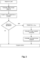
- the engine speed n and the accelerator pedal position ped are employed in the usual manner for establishing a nominal torque of the engine, i.e. a driver-determined torque setpoint. If no turbocharger supply system failure has been detected, the driver-determined torque setpoint, which is a function of n and ped, is fed to the engine control for controlling the torque actually provided by the engine, for example by controlling the fuel injection parameters accordingly.
- the corrected low-pressure compressor flow ⁇ LPC and the ambient pressure p amb are acquired and employed for determining a correction value, which is used for modifying the driver-determined torque setpoint to obtain a corrected torque setpoint.
- the correction value is chosen to limit to torque setpoint such that turbocharger surge or overspeed is safely avoided.
- the torque request is reduced as a function of ambient pressure p amb and corrected low-pressure compressor flow ⁇ LPC .
- the ambient pressure p amb mainly is due to altitude.
- the corrected low-pressure compressor flow ⁇ LPC can be determined from the total flow, i.e. fuel plus air flow, corrected in terms of temperature and pressure.
- T inlet and T ref are inlet and reference temperatures
- p inlet and p ref are inlet and reference pressures, respectively.
- the corrected torque setpoint is provided to the engine control.
- the fuel injection parameters are controlled such that no surge or overspeed can occur.
- Fig. 3 shows an example of a closed-loop control based on pressure ratio control.
- the flow diagram shown in Fig. 3 refers to the case that a turbocharger valve supply system failure has been detected, corresponding to the lower-right branch in Fig. 2 .
- the pressure ratio PR meas in the air intake system is measured, which in the case of valve failure in particular is the ratio between the downstream and the upstream pressures of the low-pressure compressor.
- the current flow in the intake airway is measured; in particular the corrected low-pressure compressor flow ⁇ LPC is determined.
- a limiting pressure ratio PR limit is determined according to a pre-determined map.
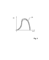
- Fig. 4 symbolically shows a typical compressor map according to which the limiting pressure ratio PR limit is determined.
- the map comprises a hysteresis band 20 for real-time implementation.
- the lower curve represents the measured PR meas
- the upper curve represents the limiting pressure ratio PR limit .
- the measured pressure ratio PR meas must not exceed the limiting pressure ratio PR limit .
- the limiting pressure ratio PR limt is compared to the measured pressure ratio PR meas . If PR meas does not exceed PR limit , a fuel quantity setpoint is determined, and fed to the engine control including the actual fuel quantity fq meas . In this case, the low-pressure compressor is far enough from surge or overspeed conditions, so that effectively no fuel quantity limitation is required. On the other hand, if PR meas exceeds PR limit , a fuel quantity offset is calculated and employed for calculating a corrected fuel quantity setpoint which is limited to avoid turbocharger surge or overspeed. The offset is calculated by using a pressure ratio setpoint that is within the hysteresis band (see Fig. 4 ).
- the compressor pressure ratio can be kept within the PR limit threshold.
- the corrected fuel quantity setpoint is employed by the engine control, including the measured fuel quantity fq meas for closed-loop control.
- FIG. 5 A further embodiment of the invention is shown in Fig. 5 also corresponding to the lower-right branch in Fig. 2 , i.e. the case that a turbocharger valve supply system failure has been detected.
- the limiting torque curve is based on the corrected low-pressure compressor flow ⁇ LPC and the ambient pressure p amb .
- a minimum function providing the minimum of the torque setpoint tq sp , LPC determined in this way and a fixed torque setpoint limit tq limit to the engine control ensures that the permissible torque threshold is never exceeded.
- the engine speed n a desired inner torque tq inr
- the corrected low-pressure compressor flow ⁇ LPC the ambient pressure p amb
- the inner torque tq inr is the torque due to combustion only, excluding losses by pumping, friction, accessory loads, etc.
- the torque-to-quantity map is modified including the low-pressure flow and the ambient pressure.
- the 4-dimensional lookup table or map may depend on the engine operating mode, thus different lookup tables or maps may be employed in normal engine operation, in diesel particle filter regeneration mode, in NO x aftertreatment mode, etc.
Landscapes
- Engineering & Computer Science (AREA)
- Chemical & Material Sciences (AREA)
- Combustion & Propulsion (AREA)
- Mechanical Engineering (AREA)
- General Engineering & Computer Science (AREA)
- Supercharger (AREA)
Abstract
Description
- The present invention relates to a method for operating an internal combustion engine equipped with a turbocharger arrangement and to a control unit for such an engine.
- Internal combustion engines, in particular diesel and gasoline engines, are frequently equipped with turbochargers. A turbocharger operates by compression of the intake airflow into the engine in order to achieve more power. In particular, a predetermined power can be generated by a turbocharged engine with a smaller displacement volume and thus smaller size and less weight, thereby achieving an increased specific power and a reduction of fuel consumption. In general, turbochargers are driven by the exhaust flow of the internal combustion engine. To this end, a turbocharger comprises a turbine arranged in the exhaust flow of the internal combustion engine, driving a compressor for compressing the intake airflow of the engine via a connecting drive shaft.
- Recently, in particular for in-line engines, series sequential turbocharging has become popular. A regulated two-stage turbocharging system comprises a low-pressure (LP) stage for peak power and a high-pressure (HP) stage for performance and for fulfilling the back pressure requirements for driving exhaust gas recirculation, which is needed for NOx pollutant emission reduction. Moreover, the HP turbine usually is smaller and more responsive than the LP turbine. The HP and LP turbines are arranged sequentially in the exhaust flow of the internal combustion engine, the LP turbine being located downstream the HP turbine. The LP and HP compressors are arranged sequentially as well, the HP compressor being located in the intake airflow downstream the LP compressor.
- The exhaust flow and/or the intake airflow are controlled by one or more bypass valves located in branches of the exhaust and/or intake system, which are parallel to the respective turbine and/or compressor. In particular, the exhaust flow may be controlled by a bypass valve of the HP turbine (turbine bypass valve, TBV) and a wastegate (WG) for bypassing the LP turbine. With the bypass valve closed, the respective turbine is driven maximally, while with the bypass valve partially or fully opened, the parallel branch is passed by at least part of the exhaust flow, the respective turbine being driven at a reduced rate. Similarly, the intake airflow may be controlled by a compressor bypass valve of the HP compressor (CBV). The bypass valves ensure a smooth operation of the engine and also ensure respecting various further constraints, concerning for example exhaust composition, compressor outlet temperature and turbine inlet temperature, as well as avoiding turbocharger surge or overspeed.
- The bypass valves may be controlled actively, for example, electrically or by vacuum, and may comprise a position feedback sensor. As the HP turbine bypass valve (TBV) is critical to emissions control, it is usually actively controlled and equipped with a position feedback sensor. The LP turbine bypass valve (WG) usually also is actively operated. For high speeds and loads, the wastegate (WG) actuator normally is used as a boost pressure limiter, hence high levels of accuracy are not required and consequently no position feedback is required for the WG. The compressor bypass valve (CBV) may be equipped for active actuation with position feedback, but for reasons of cost and complexity reduction, it usually is passive with no position feedback, i.e. it opens or closes due to the pressure difference across it, and, in particular, has only two possible positions, which are the fully open and the fully closed positions.
- The active valves usually have a default or "failsafe" position into which they move when there is no vacuum or electrical supply. The failsafe position normally is either fully open or fully closed. The default setting is determined by factors such as safety and engine power requirements at altitude. In particular, with a vacuum or electrical supply failure, the TBV is fully open, and the WG is fully closed, in order to ensure minimal damage to the HP compressor and some basic driveability. In that case, only the LP turbocharger is used, since the HP turbine is effectively bypassed. With a suitable calibration, it may be possible to achieve low particle emission even in this case.
- However, this is not sufficient to ensure avoidance of compressor surge or overspeed, since these events can occur at exhaust lambda values greater than 1.2. As in this case the valve actuators are inoperable, there is no effective boost pressure control for surge or overspeed protection. At altitude, this effect is more pronounced.
- It is an object of the present invention to provide a method for operating an internal combustion engine equipped with a turbocharger arrangement, the method permitting improved turbocharger surge or overspeed protection in case of turbocharger valve supply failure. It is a further object of the invention to provide a control unit for an internal combustion engine with a turbocharger arrangement permitting improved turbocharger surge or overspeed protection in case of such valve supply failure.
- This object is met by a method according to
claim 1 and by a control unit according toclaim 7. - The inventive method for operating an internal combustion engine refers to an internal combustion engine that is equipped with a turbocharger arrangement or turbocharger system comprising a low-pressure turbocharging stage and a high-pressure turbocharging stage, which are arranged sequentially. The low-pressure turbocharging stage comprises a low-pressure turbocharger which comprises a low-pressure turbine driving a low-pressure compressor. The high-pressure turbocharging stage comprises a high-pressure turbocharger, comprising, in particular, a high-pressure turbine driving a high-pressure compressor. The high-pressure compressor is arranged downstream the low-pressure compressor in the intake airflow of the internal combustion engine. The low-pressure turbine is located downstream the high-pressure turbine in the exhaust flow of the engine.
- The turbocharger arrangement further comprises at least one turbocharger control valve for controlling the turbocharger arrangement. In particular, the low-pressure turbine may exhibit a low-pressure turbine bypass valve (WG). The high-pressure turbine may exhibit a high-pressure turbine bypass valve (TBV). The at least one turbocharger control valve is configured to be actuated actively by a turbocharger valve supply system, which may comprise, for example, vacuum or electric transmission means. The at least one turbocharger control valve may be operated in a closed-loop control, employing the boost pressure for controlling the valve, for example.
- The turbocharger arrangement may comprise further valves. Thus, for example, the high-pressure compressor may exhibit a compressor bypass valve (CBV). The CBV may be passive, i.e. operated only by the pressure difference acting across it. The compressor bypass valve may be limited to only two operational states, which are the fully open and the fully closed positions.
- According to the inventive method, it is determined whether the turbocharger valve supply system is in an operational state or in a failure state. A supply system fai lure, in particular a failure of the electrical or vacuum system employed for actuating the at least one turbocharger control valve, may be detected by a diagnostic system in a standard engine control unit (ECU), which evaluates one or several sensor signals for detecting failure modes. A failure of the turbocharger valve supply system may as well be detectable by a dedicated sensor system. An exemplary method for detecting a failure mode of the low-pressure turbine bypass valve, which may be indicative of a supply system failure, is disclosed in
EP 11155167.7 - If a failure of the turbocharger valve supply system is detected, a low-pressure compressor flow is determined. The intake airway of the engine may be equipped with a flow sensor for measuring the low-pressure compressor flow. The flow sensor may be located, for example, directly downstream of the air filter. The low-pressure compressor flow may be determined as well, however, based on any other single or multiplicity of sensor signals representative of intake mass airflow. The low-pressure compressor flow may be measured only after a supply system failure has been detected or may be monitored continuously.
- According to the inventive method, an engine control parameter setpoint is limited, the limit depending on the low-pressure compressor flow. The control parameter subject to the modified setpoint is employed for controlling the engine.
- By limiting an engine control parameter setpoint, the limit depending on the low-pressure compressor flow, it can be ensured that turbocharger surge or overspeed, in particular of the low-pressure turbocharger, is avoided. Moreover, in spite of valve system supply failure, least interference with engine control and optimal power, drivability and emissions control can be achieved.
- According to a preferred embodiment of the invention, the engine parameter that is limited depending on the low-pressure compressor flow is the quantity of fuel provided to the engine per time unit, in particular the fuel quantity injected per time unit. The fuel quantity is controllable by the driver by pressing the accelerator pedal. Thus, in general, the fuel quantity depends on the pedal position, however, according to the invention the fuel quantity preferably is subject to an additional limitation depending on the low-pressure compressor flow. In this way, turbocharger surge or overspeed protection can be achieved in a particularly simple and cost-effective manner.
- Preferably, the fuel quantity setpoint is limited by imposing an offset to the fuel quantity injected, the offset being controlled in a closed loop. In particular, the offset may be controlled depending on the low-pressure compressor pressure ratio.
- Alternatively or additionally, the engine torque may be limited depending on the low-pressure compressor flow. The torque produced by the engine generally is controllable by the driver by pressing the accelerator pedal; however, according to the invention it may be limited depending on low-pressure compressor flow. In this way, turbocharger surge or overspeed can also be avoided in a particularly simple and cost-effective manner.
- The term "setpoint" as employed in the present invention does not necessarily imply the presence of an underlying control loop. In particular, injected fuel quantity or torque need not be measured, although there might be as well a corresponding measurement fed into a control loop. Thus, for example, the driver input via the pedal may be considered a torque request which is filtered and limited, or augmented in some way for various reasons, e.g. for engine overheating protection or vehicle dynamics torque interventions. At the end of this procedure, a torque setpoint results, which may be subject to a further limitation according to the present invention. The torque setpoint may be converted into a fuel quantity request that is passed to the fuel injector drivers. Such fuel setpoint may be limited according to the invention as well.
- According to a preferred embodiment of the invention, the engine control parameter is limited only when the low-pressure compressor flow is in a predetermined range, the predetermined range representing, in particular, low-pressure compressor flow values at or near surge or overspeed condition. As outside that range there is no risk of surge or overspeed, the engine control parameter need not be modified even in case of turbocharger valve supply system failure. Thus, surge or overspeed protection can be achieved without affecting engine operation, when conditions are not critical.
- Most preferably, the limit imposed on the engine control parameter, for example the fuel quantity or torque limit, depends on ambient conditions, in particular on ambient pressure. As surge or overspeed are more likely to occur at high altitude, in this way a particularly effective surge or overspeed protection can be provided.
- According to a further aspect of the invention, a control unit for controlling a turbocharger arrangement of an internal combustion engine is configured to operate according to a method as described above. In particular, the control unit comprises at least one signal input port for capturing at least one sensor signal indicative of a turbocharger valve supply system failure, or a diagnostic function for detecting a turbocharger valve supply system failure based on other information available to the control unit. The control unit comprises at least one signal input port for capturing at least one sensor signal indicative of the low-pressure compressor flow, or is configured for determining the low-pressure compressor flow based on other information available. The control unit further comprises data processing means; the data processing means being configured for establishing a limit to an engine control parameter setpoint, depending on the low-pressure compressor flow. The processing means may be, in particular, configured for limiting fuel quantity or torque depending on the low-pressure compressor flow. The control unit may further comprise data storage means for storing a map or a lookup table, for example, employed in determining the limit to the engine control parameter. The control unit is further configured for feeding such modified control parameter setpoint to the engine control for controlling, for example, fuel quantity or torque according to the modified setpoint. The control unit may be or may be part of an electronic engine control unit (ECU). Further aspects of the present invention will be apparent from the Figures and from the description of preferred embodiments that follows.
- Fig. 1
- shows a simplified block diagram of an internal combustion engine with a series sequential turbocharger arrangement;
- Fig. 2
- is a simplified flow diagram of a method for controlling an internal combustion engine according to a first embodiment of the invention;
- Fig. 3
- is a simplified flow diagram of a method for controlling an internal combustion engine according to a second embodiment of the invention;
- Fig. 4
- shows an exemplary relationship between low-pressure compressor flow and pressure ratio;
- Fig. 5
- is a simplified flow diagram of a method for controlling an internal combustion engine according to a third embodiment of the invention, and
- Fig. 6
- is a simplified flow diagram of a method for controlling an internal combustion engine according to a fourth embodiment of the invention.
- According to the example shown schematically in
Fig. 1 , aninternal combustion engine 1 exhibits aturbocharger arrangement 2 or turbocharger system comprising a high-pressure turbocharger 3 and a low-pressure turbocharger 4. The high-pressure turbocharger 3 comprises a high-pressure turbine 5 and a high-pressure compressor 6, thecompressor 6 being driven by theturbine 5 via adrive shaft 7. The low-pressure turbocharger 4 comprises a low-pressure turbine 8 driving a low-pressure compressor 9 by means of adrive shaft 10. Theturbines exhaust system 11 of the internal combustion engine, the high-pressure turbine 5 being arranged upstream the low-pressure turbine 8, i.e. in a section with higher pressure. Correspondingly, thecompressors intake system 12 of theengine 1, the high-pressure compressor 6 being located downstream the low-pressure compressor 9. The direction of airflow in theintake system 12 and the direction of exhaust flow in theexhaust system 11 are indicated by thearrows pressure turbine 5 and the high-pressure compressor 6 are smaller than the low-pressure turbine 8 and the low-pressure compressor 9, respectively. Anintercooler 18 is included downstream the HP compressor, which is indicated symbolically inFig. 1 . - A high-pressure turbine bypass valve 15 (TBV) is arranged in a parallel branch of the exhaust system parallel to the high-
pressure turbine 5. Therefore, a full or partial opening of the high-pressureturbine bypass valve 15 creates a bypass for the exhaust flow to partially or completely bypass the high-pressure turbine 5. If the exhaust flow partially or completely passes through thebypass valve 15, the high-pressure turbine 5 is consequently driven at a reduced rate. The operation of the high-pressure turbocharger 3 can thus be controlled by the operation of theTBV 15. For this purpose, theTBV 15 is actively controlled, serving as an actuator in theturbocharger arrangement 2, by an electrical or vacuum valve supply system (not shown). In a similar manner, a low-pressure turbine bypass valve 16 (WG) is arranged in a parallel branch of theexhaust system 11 parallel to the low-pressure turbine 8. TheWG 16 is also actively operated, serving as an actuator, by an electrical or vacuum valve supply system (not shown). - In the
intake system 12, the intake air flows through the low-pressure compressor 9, being compressed in a first stage of compression. Thereafter, the intake air flows through the high-pressure compressor 6 representing a second stage of compression, or through a parallel branch arranged parallel to the high-pressure compressor 6. The parallel branch can be opened or closed by a compressor bypass valve 17 (CBV). TheCBV 17 is passive, i.e. operated by the pressure difference acting across it. - One or several flow and/or pressure sensors may be located in the
intake system 12, asensor 19 being indicated symbolically inFig. 1 . The boost pressure, which is provided by theturbocharger arrangement 2 and which is fed into the internal combustion engine, may be measured roughly at the same position. Theengine 1 may be also equipped with an exhaust gas recirculation, which is not shown inFig. 1 . - In normal operation, the
turbocharger arrangement 2 is operated according to the engine speed and/or torque. At low engine speed and/or torque, theWG 16 is set to the fully closed position, and theTBV 15 is employed for controlling the boost pressure of theturbocharger arrangement 2, preferably in a closed-loop control, according to an engine operation point. Due to the pressure difference acting, theCBV 17 is forced into the fully closed position. In this way, optimal performance in the lowspeed/torque domain can be provided, as well as the back pressure required for exhaust gas recirculation. At higher engine speed and/or torque, theTBV 15 is set to the fully open position, and theWG 16 is employed for controlling the boost pressure of theturbocharger arrangement 2, preferably in a closed-loop control employing the boost pressure. TheCBV 17 moves into the fully open position. In this way, peak power can be provided. Alternatively, depending on the current engine speed and/or load and the current position of theCBV 17, both of the low-pressure and the high-pressure turbine valves - The
valves TBV 15 being fully open, and theWG 16 being fully closed. Thus, in case of vacuum or electrical supply failure, the high-pressure turbine 5 is bypassed, the high-pressure compressor not being driven by the exhaust. The low-pressure turbine 8 and thus the low-pressure compressor 9 is driven by the entire exhaust in that case, which provides advantages for maximizing engine power and minimizing particle emission, however bears the risk of turbocharger surge or overspeed. A sensor for detecting a failure of the vacuum or electric supply system of thevalves - As shown in
Fig. 2 , according to a first embodiment of the invention, the engine speed n and the accelerator pedal position ped are employed in the usual manner for establishing a nominal torque of the engine, i.e. a driver-determined torque setpoint. If no turbocharger supply system failure has been detected, the driver-determined torque setpoint, which is a function of n and ped, is fed to the engine control for controlling the torque actually provided by the engine, for example by controlling the fuel injection parameters accordingly. - If, however, a failure of the valve supply system has been detected, the corrected low-pressure compressor flow ϕ LPC and the ambient pressure pamb are acquired and employed for determining a correction value, which is used for modifying the driver-determined torque setpoint to obtain a corrected torque setpoint. The correction value is chosen to limit to torque setpoint such that turbocharger surge or overspeed is safely avoided. Effectively, the torque request is reduced as a function of ambient pressure pamb and corrected low-pressure compressor flow ϕ LPC . The ambient pressure pamb mainly is due to altitude. The corrected low-pressure compressor flow ϕ LPC can be determined from the total flow, i.e. fuel plus air flow, corrected in terms of temperature and pressure. For example, the corrected low-pressure compressor flow ϕ LPC may be calculated by

- where Tinlet and Tref are inlet and reference temperatures, and pinlet and pref are inlet and reference pressures, respectively. The corrected torque setpoint is provided to the engine control. Thus, the fuel injection parameters are controlled such that no surge or overspeed can occur.
-
Fig. 3 shows an example of a closed-loop control based on pressure ratio control. The flow diagram shown inFig. 3 refers to the case that a turbocharger valve supply system failure has been detected, corresponding to the lower-right branch inFig. 2 . - According to
Fig. 3 , the pressure ratio PRmeas in the air intake system is measured, which in the case of valve failure in particular is the ratio between the downstream and the upstream pressures of the low-pressure compressor. Moreover, the current flow in the intake airway is measured; in particular the corrected low-pressure compressor flow ϕ LPC is determined. Depending on the current values of the pressure ratio PRmeas and the corrected low-pressure compressor flow ϕ LPC , a limiting pressure ratio PRlimit is determined according to a pre-determined map. -
Fig. 4 symbolically shows a typical compressor map according to which the limiting pressure ratio PRlimit is determined. The map comprises ahysteresis band 20 for real-time implementation. The lower curve represents the measured PRmeas , while the upper curve represents the limiting pressure ratio PRlimit. For component integrity, the measured pressure ratio PRmeas must not exceed the limiting pressure ratio PRlimit . - Returning to
Fig. 3 , the limiting pressure ratio PRlimt is compared to the measured pressure ratio PRmeas. If PRmeas does not exceed PRlimit , a fuel quantity setpoint is determined, and fed to the engine control including the actual fuel quantity fqmeas. In this case, the low-pressure compressor is far enough from surge or overspeed conditions, so that effectively no fuel quantity limitation is required. On the other hand, if PRmeas exceeds PRlimit , a fuel quantity offset is calculated and employed for calculating a corrected fuel quantity setpoint which is limited to avoid turbocharger surge or overspeed. The offset is calculated by using a pressure ratio setpoint that is within the hysteresis band (seeFig. 4 ). Thus, by adding a controlled, negative fuel offset, the compressor pressure ratio can be kept within the PRlimit threshold. There may be maximum fuel quantity offset to be added, which cannot be exceeded. The corrected fuel quantity setpoint is employed by the engine control, including the measured fuel quantity fqmeas for closed-loop control. - A further embodiment of the invention is shown in
Fig. 5 also corresponding to the lower-right branch inFig. 2 , i.e. the case that a turbocharger valve supply system failure has been detected. According toFig. 5 , the limiting torque curve is based on the corrected low-pressure compressor flow ϕ LPC and the ambient pressure pamb. A minimum function providing the minimum of the torque setpoint tq sp,LPC determined in this way and a fixed torque setpoint limit tqlimit to the engine control ensures that the permissible torque threshold is never exceeded. - As shown symbolically in
Fig. 6 , in the case that a turbocharger valve supply system failure has been detected (lower right branch inFig. 2 ), the engine speed n, a desired inner torque tqinr , the corrected low-pressure compressor flow ϕ LPC , and the ambient pressure pamb are acquired in conjunction, and employing a 4-dimensional lookup table a corrected fuel quantity setpoint can be determined directly. The inner torque tqinr is the torque due to combustion only, excluding losses by pumping, friction, accessory loads, etc. Shortly speaking, thus the torque-to-quantity map is modified including the low-pressure flow and the ambient pressure. The 4-dimensional lookup table or map may depend on the engine operating mode, thus different lookup tables or maps may be employed in normal engine operation, in diesel particle filter regeneration mode, in NOx aftertreatment mode, etc. - In any of the examples shown, safe protection against turbocharger surge or overspeed can be achieved.
-
- 1
- Internal combustion engine
- 2
- Turbocharger arrangement
- 3
- High-pressure turbocharger
- 4
- Low-pressure turbocharger
- 5
- High-pressure turbine
- 6
- High-pressure compressor
- 7
- Drive shaft
- 8
- Low-pressure turbine
- 9
- Low-pressure compressor
- 10
- Drive shaft
- 11
- Exhaust system
- 12
- Intake system
- 13
- Flow direction intake air
- 14
- Flow direction exhaust gas
- 15
- High-pressure turbine bypass valve
- 16
- Low-pressure turbine bypass valve
- 17
- Compressor bypass valve
- 18
- Sensor
- 19
- Intercooler
- 20
- Hysteresis band
Claims (7)
- Method for operating an internal combustion engine (1) with a turbocharger arrangement (2) comprising a low-pressure and a high-pressure stage arranged sequentially, the low-pressure stage comprising a low-pressure compressor (9), and at least one turbocharger control valve (15, 16) operable by a supply system, the method comprising detecting a supply system failure, determining a low-pressure compressor flow and limiting an engine control parameter setpoint depending on the low-pressure compressor flow.
- Method according to claim 1,
characterized in that
a fuel quantity setpoint is limited. - Method according to claim 2,
characterized in that
the fuel quantity setpoint is limited by imposing an offset to the fuel quantity, the offset being controlled in a closed loop. - Method according to any one of the preceding claims,
characterized in that
an engine torque setpoint is limited. - Method according to any one of the preceding claims,
characterized in that
the engine control parameter limit is limited only when the low-pressure compressor flow is in a predetermined range. - Method according to any one of the preceding claims,
characterized in that
the engine control parameter limit depends on ambient pressure p amb. - Control unit for an internal combustion engine (1) with a turbocharger arrangement (2) comprising a low-pressure and a high-pressure stage arranged sequentially, the low-pressure stage comprising a low-pressure compressor (9), and at least one turbocharger control valve operable by a supply system,
characterized in that
the control unit is configured for controlling the internal combustion engine (1) according to a method according to any one of the preceding claims.
Priority Applications (3)
| Application Number | Priority Date | Filing Date | Title |
|---|---|---|---|
| EP12155511.4A EP2628918B1 (en) | 2012-02-15 | 2012-02-15 | Method for operating an internal combustion engine with a turbocharger arrangement and control unit for an engine with a turbocharger arrangement |
| US13/750,821 US9169796B2 (en) | 2012-02-15 | 2013-01-25 | Method for operating an internal combustion engine with a turbocharger arrangement and control unit for an engine with a turbocharger arrangement |
| CN201310049035.XA CN103256129B (en) | 2012-02-15 | 2013-02-07 | The operating method and its control unit of the internal combustion engine with turbo charging installation |
Applications Claiming Priority (1)
| Application Number | Priority Date | Filing Date | Title |
|---|---|---|---|
| EP12155511.4A EP2628918B1 (en) | 2012-02-15 | 2012-02-15 | Method for operating an internal combustion engine with a turbocharger arrangement and control unit for an engine with a turbocharger arrangement |
Publications (2)
| Publication Number | Publication Date |
|---|---|
| EP2628918A1 true EP2628918A1 (en) | 2013-08-21 |
| EP2628918B1 EP2628918B1 (en) | 2020-04-22 |
Family
ID=45655795
Family Applications (1)
| Application Number | Title | Priority Date | Filing Date |
|---|---|---|---|
| EP12155511.4A Not-in-force EP2628918B1 (en) | 2012-02-15 | 2012-02-15 | Method for operating an internal combustion engine with a turbocharger arrangement and control unit for an engine with a turbocharger arrangement |
Country Status (3)
| Country | Link |
|---|---|
| US (1) | US9169796B2 (en) |
| EP (1) | EP2628918B1 (en) |
| CN (1) | CN103256129B (en) |
Cited By (2)
| Publication number | Priority date | Publication date | Assignee | Title |
|---|---|---|---|---|
| EP3567234A1 (en) * | 2018-05-07 | 2019-11-13 | Garrett Transportation I Inc. | Method for controlling an inlet-adjustment mechanism for a turbocharger compressor |
| CN113279865A (en) * | 2021-04-21 | 2021-08-20 | 潍柴动力股份有限公司 | Control method of engine, controller of engine and vehicle |
Families Citing this family (19)
| Publication number | Priority date | Publication date | Assignee | Title |
|---|---|---|---|---|
| BRPI1004924B1 (en) * | 2009-01-13 | 2020-07-21 | Man Truck & Bus Ag. | "method for operating exhaust gas after-treatment components and exhaust gas after-treatment device" |
| FR2980525B1 (en) * | 2011-09-26 | 2013-08-30 | Renault Sa | METHOD AND SYSTEM FOR DIAGNOSING A MOTOR PUMPS GROUP WITH TWO TURBOCHARGERS. |
| EP2786909A4 (en) * | 2011-12-02 | 2015-12-30 | Toyota Motor Co Ltd | HYBRID VEHICLE |
| JP6201524B2 (en) * | 2013-08-26 | 2017-09-27 | マツダ株式会社 | Turbocharger for vehicle engine |
| WO2016048359A1 (en) * | 2014-09-26 | 2016-03-31 | Cummins, Inc. | Systems and methods for multiple actuators to limit engine speed |
| US10738720B2 (en) | 2014-09-29 | 2020-08-11 | Volvo Truck Corporation | Method for controlling an air boosting apparatus in a two-stroke, opposed piston engine, and a two-stroke, opposed piston engine with an air boosting apparatus |
| US9745906B2 (en) * | 2014-12-10 | 2017-08-29 | Ford Global Technologies, Llc | Methods and system for improving compressor recirculation valve operation |
| JP6557618B2 (en) * | 2016-03-02 | 2019-08-07 | アズビル株式会社 | Flow control device |
| US10066541B2 (en) * | 2016-04-29 | 2018-09-04 | Fca Us Llc | Physics-based vehicle turbocharger control techniques |
| US10584630B2 (en) | 2016-06-06 | 2020-03-10 | Fca Us Llc | Power-based turbocharger boost control techniques |
| JP6785712B2 (en) * | 2017-04-26 | 2020-11-18 | ヤンマーパワーテクノロジー株式会社 | Multi-stage turbocharging system |
| US11022060B2 (en) * | 2017-06-08 | 2021-06-01 | Cummins Inc. | Diagnostic systems and methods for isolating failure modes of a vehicle |
| GB2570152B8 (en) * | 2018-01-04 | 2020-06-03 | Ford Global Tech Llc | A method of operating an engine assembly |
| CN110657991B (en) * | 2018-06-29 | 2021-05-07 | 中国航发商用航空发动机有限责任公司 | Surge monitoring method and surge monitoring system of aircraft engine |
| BE1026577B1 (en) * | 2018-08-29 | 2020-03-30 | Atlas Copco Airpower Nv | Compressor or pump provided with a control for the control of a control parameter and method for the control applied |
| CN109611193B (en) * | 2018-10-23 | 2021-05-11 | 航天时代飞鸿技术有限公司 | Control method for small-sized aviation piston two-stroke turbocharged engine |
| JP7243420B2 (en) * | 2019-05-07 | 2023-03-22 | トヨタ自動車株式会社 | vehicle |
| CN112431786B (en) * | 2020-11-12 | 2022-03-11 | 一汽解放汽车有限公司 | A structure for preventing surge of a supercharger and an engine intake and exhaust system |
| SE545437C2 (en) * | 2020-12-11 | 2023-09-12 | Scania Cv Ab | Controlling Valve Actuation of an Internal Combustion Engine |
Citations (5)
| Publication number | Priority date | Publication date | Assignee | Title |
|---|---|---|---|---|
| EP1115516A1 (en) | 1998-09-24 | 2001-07-18 | Metaalbedrijf Busschers B.V. | Apparatus and method for bending tubular or rod-shaped material |
| DE102008005800A1 (en) * | 2008-01-24 | 2009-07-30 | Ford Global Technologies, LLC, Dearborn | Method for boost pressure limitation in internal combustion engine provided with turbocharger system, involves presetting boost pressure reference value for limiting boost pressure depending on variable characteristic for air mass flow |
| DE102008018133A1 (en) * | 2008-04-10 | 2010-03-18 | Ford Global Technologies, LLC, Dearborn | Method for operating internal-combustion engine, involves arranging exhaust turbocharger, another exhaust turbocharger and shut-off valves in fresh air branch or exhaust gas branch with exhaust turbocharger arrangement |
| DE102009043408A1 (en) * | 2008-10-15 | 2010-04-22 | Denso Corporation, Kariya-City | Malfunction detection device for use in intake air system of internal combustion engine i.e. diesel engine, has supercharger evaluating leakage of intake air when charging pressure is lower than threshold valve |
| JP2010216402A (en) * | 2009-03-18 | 2010-09-30 | Isuzu Motors Ltd | Diagnostic device for supercharged engine provided with a plurality of turbochargers |
Family Cites Families (14)
| Publication number | Priority date | Publication date | Assignee | Title |
|---|---|---|---|---|
| DE4310261A1 (en) * | 1993-03-30 | 1994-10-06 | Bosch Gmbh Robert | Protection system for an internal combustion engine operated with supercharging |
| JPH07208230A (en) * | 1994-01-27 | 1995-08-08 | Daihatsu Motor Co Ltd | Engine boost pressure control method |
| US5447031A (en) * | 1994-04-20 | 1995-09-05 | Caterpillar Inc. | Wastegate failure detection apparatus and method for operating same |
| US5873248A (en) * | 1996-06-21 | 1999-02-23 | Caterpillar Inc. | Turbocharger control system |
| JP4024423B2 (en) * | 1999-03-31 | 2007-12-19 | 日産ディーゼル工業株式会社 | Fuel injection amount control device for an internal combustion engine with a turbocharger |
| US6155050A (en) * | 1999-06-01 | 2000-12-05 | Cummins Engine Co Inc | System and method for protecting a turbocharger in the event of a wastegate failure |
| DE10207469A1 (en) * | 2002-02-21 | 2003-09-18 | Audi Ag | Method and device for checking the function of a bypass element of a boost pressure control of a turbo engine |
| US6655141B1 (en) * | 2002-05-14 | 2003-12-02 | Caterpillar Inc | Airflow system for engine with series turbochargers |
| CN101082318B (en) * | 2006-05-31 | 2011-09-21 | 卡特彼勒公司 | Turbo-charger control system |
| EP2455595A4 (en) * | 2009-07-16 | 2018-01-03 | Toyota Jidosha Kabushiki Kaisha | Device for determining abnormality of control valve in internal combustion engine |
| EP2489850B1 (en) | 2011-02-21 | 2013-08-21 | Ford Global Technologies, LLC | Method for operating a turbocharger arrangement and control unit for a turbocharger arrangement |
| EP2489851B1 (en) * | 2011-02-21 | 2016-08-17 | Ford Global Technologies, LLC | Method for operating a turbocharger arrangement and control unit for a turbocharger arrangement |
| US8701477B2 (en) * | 2011-09-16 | 2014-04-22 | General Electric Company | Methods and systems for diagnosing a turbocharger |
| US8849548B2 (en) * | 2011-11-21 | 2014-09-30 | Caterpillar Inc. | Anti-sticking and diagnostic strategy for exhaust system valves |
-
2012
- 2012-02-15 EP EP12155511.4A patent/EP2628918B1/en not_active Not-in-force
-
2013
- 2013-01-25 US US13/750,821 patent/US9169796B2/en active Active
- 2013-02-07 CN CN201310049035.XA patent/CN103256129B/en not_active Expired - Fee Related
Patent Citations (5)
| Publication number | Priority date | Publication date | Assignee | Title |
|---|---|---|---|---|
| EP1115516A1 (en) | 1998-09-24 | 2001-07-18 | Metaalbedrijf Busschers B.V. | Apparatus and method for bending tubular or rod-shaped material |
| DE102008005800A1 (en) * | 2008-01-24 | 2009-07-30 | Ford Global Technologies, LLC, Dearborn | Method for boost pressure limitation in internal combustion engine provided with turbocharger system, involves presetting boost pressure reference value for limiting boost pressure depending on variable characteristic for air mass flow |
| DE102008018133A1 (en) * | 2008-04-10 | 2010-03-18 | Ford Global Technologies, LLC, Dearborn | Method for operating internal-combustion engine, involves arranging exhaust turbocharger, another exhaust turbocharger and shut-off valves in fresh air branch or exhaust gas branch with exhaust turbocharger arrangement |
| DE102009043408A1 (en) * | 2008-10-15 | 2010-04-22 | Denso Corporation, Kariya-City | Malfunction detection device for use in intake air system of internal combustion engine i.e. diesel engine, has supercharger evaluating leakage of intake air when charging pressure is lower than threshold valve |
| JP2010216402A (en) * | 2009-03-18 | 2010-09-30 | Isuzu Motors Ltd | Diagnostic device for supercharged engine provided with a plurality of turbochargers |
Cited By (4)
| Publication number | Priority date | Publication date | Assignee | Title |
|---|---|---|---|---|
| EP3567234A1 (en) * | 2018-05-07 | 2019-11-13 | Garrett Transportation I Inc. | Method for controlling an inlet-adjustment mechanism for a turbocharger compressor |
| US10876467B2 (en) | 2018-05-07 | 2020-12-29 | Garrett Transportation I Inc. | Method for controlling an inlet-adjustment mechanism for a turbocharger compressor |
| CN113279865A (en) * | 2021-04-21 | 2021-08-20 | 潍柴动力股份有限公司 | Control method of engine, controller of engine and vehicle |
| CN113279865B (en) * | 2021-04-21 | 2022-04-26 | 潍柴动力股份有限公司 | Control method of engine, controller of engine and vehicle |
Also Published As
| Publication number | Publication date |
|---|---|
| US9169796B2 (en) | 2015-10-27 |
| EP2628918B1 (en) | 2020-04-22 |
| CN103256129B (en) | 2017-06-06 |
| US20130211693A1 (en) | 2013-08-15 |
| CN103256129A (en) | 2013-08-21 |
Similar Documents
| Publication | Publication Date | Title |
|---|---|---|
| EP2628918B1 (en) | Method for operating an internal combustion engine with a turbocharger arrangement and control unit for an engine with a turbocharger arrangement | |
| US9303556B2 (en) | Method for operating a turbocharger arrangement and control unit for a turbocharger arrangement | |
| EP2489851B1 (en) | Method for operating a turbocharger arrangement and control unit for a turbocharger arrangement | |
| KR101776591B1 (en) | Charged internal combustion engine | |
| US9046104B2 (en) | Turbocharger system with electric motor assist for high pressure turbocharger | |
| US8087402B2 (en) | Method and device for the operation of an internal combustion engine comprising an exhaust-gas turbocharger | |
| US8640459B2 (en) | Turbocharger control systems and methods for improved transient performance | |
| US20110192161A1 (en) | Engine | |
| JPH02504178A (en) | Control of supercharged internal combustion engines | |
| US20100242470A1 (en) | Model-based control of airpath pressure limits by modulating a turbo charger by-pass valve and a variable-geometry turbine | |
| CN103890353A (en) | Control device for diesel engine with turbosupercharger | |
| CN114962020B (en) | Vehicle and engine boost control methods, systems and computer equipment | |
| US8484969B2 (en) | Engine | |
| US8997559B2 (en) | Method and device for diagnosing a blowoff valve for a supercharging device of an internal combustion engine | |
| US9212612B2 (en) | Method and device for performing a control, in particular for use in a motor vehicle | |
| US20190010863A1 (en) | Control device of internal combustion engine | |
| US20140260189A1 (en) | Forced induction system with regenerative charge air control | |
| US7295914B2 (en) | Internal combustion engine with speed recovery power boost | |
| CN107829836B (en) | Air inlet control method for turbocharged engine | |
| WO2009020418A1 (en) | A surge control method | |
| JP2007291961A (en) | Control device for internal combustion engine provided with centrifugal compressor | |
| EP2772629B1 (en) | Control device for diesel engine equipped with turbocharger | |
| JPH0529768B2 (en) | ||
| JP5733162B2 (en) | Control device for diesel engine with turbocharger |
Legal Events
| Date | Code | Title | Description |
|---|---|---|---|
| PUAI | Public reference made under article 153(3) epc to a published international application that has entered the european phase |
Free format text: ORIGINAL CODE: 0009012 |
|
| AK | Designated contracting states |
Kind code of ref document: A1 Designated state(s): AL AT BE BG CH CY CZ DE DK EE ES FI FR GB GR HR HU IE IS IT LI LT LU LV MC MK MT NL NO PL PT RO RS SE SI SK SM TR |
|
| AX | Request for extension of the european patent |
Extension state: BA ME |
|
| 17P | Request for examination filed |
Effective date: 20140221 |
|
| RBV | Designated contracting states (corrected) |
Designated state(s): AL AT BE BG CH CY CZ DE DK EE ES FI FR GB GR HR HU IE IS IT LI LT LU LV MC MK MT NL NO PL PT RO RS SE SI SK SM TR |
|
| STAA | Information on the status of an ep patent application or granted ep patent |
Free format text: STATUS: EXAMINATION IS IN PROGRESS |
|
| 17Q | First examination report despatched |
Effective date: 20190627 |
|
| GRAP | Despatch of communication of intention to grant a patent |
Free format text: ORIGINAL CODE: EPIDOSNIGR1 |
|
| STAA | Information on the status of an ep patent application or granted ep patent |
Free format text: STATUS: GRANT OF PATENT IS INTENDED |
|
| INTG | Intention to grant announced |
Effective date: 20200211 |
|
| GRAS | Grant fee paid |
Free format text: ORIGINAL CODE: EPIDOSNIGR3 |
|
| GRAA | (expected) grant |
Free format text: ORIGINAL CODE: 0009210 |
|
| STAA | Information on the status of an ep patent application or granted ep patent |
Free format text: STATUS: THE PATENT HAS BEEN GRANTED |
|
| AK | Designated contracting states |
Kind code of ref document: B1 Designated state(s): AL AT BE BG CH CY CZ DE DK EE ES FI FR GB GR HR HU IE IS IT LI LT LU LV MC MK MT NL NO PL PT RO RS SE SI SK SM TR |
|
| REG | Reference to a national code |
Ref country code: GB Ref legal event code: FG4D |
|
| REG | Reference to a national code |
Ref country code: CH Ref legal event code: EP |
|
| REG | Reference to a national code |
Ref country code: DE Ref legal event code: R096 Ref document number: 602012069403 Country of ref document: DE |
|
| REG | Reference to a national code |
Ref country code: IE Ref legal event code: FG4D |
|
| REG | Reference to a national code |
Ref country code: AT Ref legal event code: REF Ref document number: 1260373 Country of ref document: AT Kind code of ref document: T Effective date: 20200515 |
|
| REG | Reference to a national code |
Ref country code: LT Ref legal event code: MG4D |
|
| REG | Reference to a national code |
Ref country code: NL Ref legal event code: MP Effective date: 20200422 |
|
| PG25 | Lapsed in a contracting state [announced via postgrant information from national office to epo] |
Ref country code: LT Free format text: LAPSE BECAUSE OF FAILURE TO SUBMIT A TRANSLATION OF THE DESCRIPTION OR TO PAY THE FEE WITHIN THE PRESCRIBED TIME-LIMIT Effective date: 20200422 Ref country code: PT Free format text: LAPSE BECAUSE OF FAILURE TO SUBMIT A TRANSLATION OF THE DESCRIPTION OR TO PAY THE FEE WITHIN THE PRESCRIBED TIME-LIMIT Effective date: 20200824 Ref country code: SE Free format text: LAPSE BECAUSE OF FAILURE TO SUBMIT A TRANSLATION OF THE DESCRIPTION OR TO PAY THE FEE WITHIN THE PRESCRIBED TIME-LIMIT Effective date: 20200422 Ref country code: NL Free format text: LAPSE BECAUSE OF FAILURE TO SUBMIT A TRANSLATION OF THE DESCRIPTION OR TO PAY THE FEE WITHIN THE PRESCRIBED TIME-LIMIT Effective date: 20200422 Ref country code: FI Free format text: LAPSE BECAUSE OF FAILURE TO SUBMIT A TRANSLATION OF THE DESCRIPTION OR TO PAY THE FEE WITHIN THE PRESCRIBED TIME-LIMIT Effective date: 20200422 Ref country code: NO Free format text: LAPSE BECAUSE OF FAILURE TO SUBMIT A TRANSLATION OF THE DESCRIPTION OR TO PAY THE FEE WITHIN THE PRESCRIBED TIME-LIMIT Effective date: 20200722 Ref country code: GR Free format text: LAPSE BECAUSE OF FAILURE TO SUBMIT A TRANSLATION OF THE DESCRIPTION OR TO PAY THE FEE WITHIN THE PRESCRIBED TIME-LIMIT Effective date: 20200723 Ref country code: IS Free format text: LAPSE BECAUSE OF FAILURE TO SUBMIT A TRANSLATION OF THE DESCRIPTION OR TO PAY THE FEE WITHIN THE PRESCRIBED TIME-LIMIT Effective date: 20200822 |
|
| REG | Reference to a national code |
Ref country code: AT Ref legal event code: MK05 Ref document number: 1260373 Country of ref document: AT Kind code of ref document: T Effective date: 20200422 |
|
| PG25 | Lapsed in a contracting state [announced via postgrant information from national office to epo] |
Ref country code: HR Free format text: LAPSE BECAUSE OF FAILURE TO SUBMIT A TRANSLATION OF THE DESCRIPTION OR TO PAY THE FEE WITHIN THE PRESCRIBED TIME-LIMIT Effective date: 20200422 Ref country code: LV Free format text: LAPSE BECAUSE OF FAILURE TO SUBMIT A TRANSLATION OF THE DESCRIPTION OR TO PAY THE FEE WITHIN THE PRESCRIBED TIME-LIMIT Effective date: 20200422 Ref country code: RS Free format text: LAPSE BECAUSE OF FAILURE TO SUBMIT A TRANSLATION OF THE DESCRIPTION OR TO PAY THE FEE WITHIN THE PRESCRIBED TIME-LIMIT Effective date: 20200422 Ref country code: BG Free format text: LAPSE BECAUSE OF FAILURE TO SUBMIT A TRANSLATION OF THE DESCRIPTION OR TO PAY THE FEE WITHIN THE PRESCRIBED TIME-LIMIT Effective date: 20200722 |
|
| PG25 | Lapsed in a contracting state [announced via postgrant information from national office to epo] |
Ref country code: AL Free format text: LAPSE BECAUSE OF FAILURE TO SUBMIT A TRANSLATION OF THE DESCRIPTION OR TO PAY THE FEE WITHIN THE PRESCRIBED TIME-LIMIT Effective date: 20200422 |
|
| REG | Reference to a national code |
Ref country code: DE Ref legal event code: R097 Ref document number: 602012069403 Country of ref document: DE |
|
| PG25 | Lapsed in a contracting state [announced via postgrant information from national office to epo] |
Ref country code: ES Free format text: LAPSE BECAUSE OF FAILURE TO SUBMIT A TRANSLATION OF THE DESCRIPTION OR TO PAY THE FEE WITHIN THE PRESCRIBED TIME-LIMIT Effective date: 20200422 Ref country code: RO Free format text: LAPSE BECAUSE OF FAILURE TO SUBMIT A TRANSLATION OF THE DESCRIPTION OR TO PAY THE FEE WITHIN THE PRESCRIBED TIME-LIMIT Effective date: 20200422 Ref country code: IT Free format text: LAPSE BECAUSE OF FAILURE TO SUBMIT A TRANSLATION OF THE DESCRIPTION OR TO PAY THE FEE WITHIN THE PRESCRIBED TIME-LIMIT Effective date: 20200422 Ref country code: CZ Free format text: LAPSE BECAUSE OF FAILURE TO SUBMIT A TRANSLATION OF THE DESCRIPTION OR TO PAY THE FEE WITHIN THE PRESCRIBED TIME-LIMIT Effective date: 20200422 Ref country code: SM Free format text: LAPSE BECAUSE OF FAILURE TO SUBMIT A TRANSLATION OF THE DESCRIPTION OR TO PAY THE FEE WITHIN THE PRESCRIBED TIME-LIMIT Effective date: 20200422 Ref country code: EE Free format text: LAPSE BECAUSE OF FAILURE TO SUBMIT A TRANSLATION OF THE DESCRIPTION OR TO PAY THE FEE WITHIN THE PRESCRIBED TIME-LIMIT Effective date: 20200422 Ref country code: AT Free format text: LAPSE BECAUSE OF FAILURE TO SUBMIT A TRANSLATION OF THE DESCRIPTION OR TO PAY THE FEE WITHIN THE PRESCRIBED TIME-LIMIT Effective date: 20200422 Ref country code: DK Free format text: LAPSE BECAUSE OF FAILURE TO SUBMIT A TRANSLATION OF THE DESCRIPTION OR TO PAY THE FEE WITHIN THE PRESCRIBED TIME-LIMIT Effective date: 20200422 |
|
| PG25 | Lapsed in a contracting state [announced via postgrant information from national office to epo] |
Ref country code: SK Free format text: LAPSE BECAUSE OF FAILURE TO SUBMIT A TRANSLATION OF THE DESCRIPTION OR TO PAY THE FEE WITHIN THE PRESCRIBED TIME-LIMIT Effective date: 20200422 Ref country code: PL Free format text: LAPSE BECAUSE OF FAILURE TO SUBMIT A TRANSLATION OF THE DESCRIPTION OR TO PAY THE FEE WITHIN THE PRESCRIBED TIME-LIMIT Effective date: 20200422 |
|
| PLBE | No opposition filed within time limit |
Free format text: ORIGINAL CODE: 0009261 |
|
| STAA | Information on the status of an ep patent application or granted ep patent |
Free format text: STATUS: NO OPPOSITION FILED WITHIN TIME LIMIT |
|
| 26N | No opposition filed |
Effective date: 20210125 |
|
| PG25 | Lapsed in a contracting state [announced via postgrant information from national office to epo] |
Ref country code: SI Free format text: LAPSE BECAUSE OF FAILURE TO SUBMIT A TRANSLATION OF THE DESCRIPTION OR TO PAY THE FEE WITHIN THE PRESCRIBED TIME-LIMIT Effective date: 20200422 |
|
| PG25 | Lapsed in a contracting state [announced via postgrant information from national office to epo] |
Ref country code: MC Free format text: LAPSE BECAUSE OF FAILURE TO SUBMIT A TRANSLATION OF THE DESCRIPTION OR TO PAY THE FEE WITHIN THE PRESCRIBED TIME-LIMIT Effective date: 20200422 |
|
| GBPC | Gb: european patent ceased through non-payment of renewal fee |
Effective date: 20210215 |
|
| REG | Reference to a national code |
Ref country code: BE Ref legal event code: MM Effective date: 20210228 |
|
| PG25 | Lapsed in a contracting state [announced via postgrant information from national office to epo] |
Ref country code: LI Free format text: LAPSE BECAUSE OF NON-PAYMENT OF DUE FEES Effective date: 20210228 Ref country code: LU Free format text: LAPSE BECAUSE OF NON-PAYMENT OF DUE FEES Effective date: 20210215 Ref country code: CH Free format text: LAPSE BECAUSE OF NON-PAYMENT OF DUE FEES Effective date: 20210228 |
|
| PG25 | Lapsed in a contracting state [announced via postgrant information from national office to epo] |
Ref country code: FR Free format text: LAPSE BECAUSE OF NON-PAYMENT OF DUE FEES Effective date: 20210228 Ref country code: IE Free format text: LAPSE BECAUSE OF NON-PAYMENT OF DUE FEES Effective date: 20210215 Ref country code: GB Free format text: LAPSE BECAUSE OF NON-PAYMENT OF DUE FEES Effective date: 20210215 |
|
| PG25 | Lapsed in a contracting state [announced via postgrant information from national office to epo] |
Ref country code: BE Free format text: LAPSE BECAUSE OF NON-PAYMENT OF DUE FEES Effective date: 20210228 |
|
| PG25 | Lapsed in a contracting state [announced via postgrant information from national office to epo] |
Ref country code: HU Free format text: LAPSE BECAUSE OF FAILURE TO SUBMIT A TRANSLATION OF THE DESCRIPTION OR TO PAY THE FEE WITHIN THE PRESCRIBED TIME-LIMIT; INVALID AB INITIO Effective date: 20120215 Ref country code: CY Free format text: LAPSE BECAUSE OF FAILURE TO SUBMIT A TRANSLATION OF THE DESCRIPTION OR TO PAY THE FEE WITHIN THE PRESCRIBED TIME-LIMIT Effective date: 20200422 |
|
| P01 | Opt-out of the competence of the unified patent court (upc) registered |
Effective date: 20230620 |
|
| PG25 | Lapsed in a contracting state [announced via postgrant information from national office to epo] |
Ref country code: MK Free format text: LAPSE BECAUSE OF FAILURE TO SUBMIT A TRANSLATION OF THE DESCRIPTION OR TO PAY THE FEE WITHIN THE PRESCRIBED TIME-LIMIT Effective date: 20200422 |
|
| PGFP | Annual fee paid to national office [announced via postgrant information from national office to epo] |
Ref country code: DE Payment date: 20240109 Year of fee payment: 13 |
|
| PG25 | Lapsed in a contracting state [announced via postgrant information from national office to epo] |
Ref country code: TR Free format text: LAPSE BECAUSE OF FAILURE TO SUBMIT A TRANSLATION OF THE DESCRIPTION OR TO PAY THE FEE WITHIN THE PRESCRIBED TIME-LIMIT Effective date: 20200422 |
|
| PG25 | Lapsed in a contracting state [announced via postgrant information from national office to epo] |
Ref country code: MT Free format text: LAPSE BECAUSE OF FAILURE TO SUBMIT A TRANSLATION OF THE DESCRIPTION OR TO PAY THE FEE WITHIN THE PRESCRIBED TIME-LIMIT Effective date: 20200422 |
|
| REG | Reference to a national code |
Ref country code: DE Ref legal event code: R119 Ref document number: 602012069403 Country of ref document: DE |
|
| PG25 | Lapsed in a contracting state [announced via postgrant information from national office to epo] |
Ref country code: DE Free format text: LAPSE BECAUSE OF NON-PAYMENT OF DUE FEES Effective date: 20250902 |