EP2628897A2 - Gas turbine system - Google Patents
Gas turbine system Download PDFInfo
- Publication number
- EP2628897A2 EP2628897A2 EP13152940.6A EP13152940A EP2628897A2 EP 2628897 A2 EP2628897 A2 EP 2628897A2 EP 13152940 A EP13152940 A EP 13152940A EP 2628897 A2 EP2628897 A2 EP 2628897A2
- Authority
- EP
- European Patent Office
- Prior art keywords
- wheel
- gas turbine
- turbine system
- airflow
- center bore
- Prior art date
- Legal status (The legal status is an assumption and is not a legal conclusion. Google has not performed a legal analysis and makes no representation as to the accuracy of the status listed.)
- Withdrawn
Links
- 230000007704 transition Effects 0.000 description 5
- 230000009467 reduction Effects 0.000 description 2
- 230000004075 alteration Effects 0.000 description 1
- 238000001816 cooling Methods 0.000 description 1
- 230000003993 interaction Effects 0.000 description 1
- 238000006467 substitution reaction Methods 0.000 description 1
- 238000011144 upstream manufacturing Methods 0.000 description 1
Images



Classifications
-
- F—MECHANICAL ENGINEERING; LIGHTING; HEATING; WEAPONS; BLASTING
- F01—MACHINES OR ENGINES IN GENERAL; ENGINE PLANTS IN GENERAL; STEAM ENGINES
- F01D—NON-POSITIVE DISPLACEMENT MACHINES OR ENGINES, e.g. STEAM TURBINES
- F01D5/00—Blades; Blade-carrying members; Heating, heat-insulating, cooling or antivibration means on the blades or the members
- F01D5/02—Blade-carrying members, e.g. rotors
- F01D5/08—Heating, heat-insulating or cooling means
- F01D5/085—Heating, heat-insulating or cooling means cooling fluid circulating inside the rotor
-
- F—MECHANICAL ENGINEERING; LIGHTING; HEATING; WEAPONS; BLASTING
- F01—MACHINES OR ENGINES IN GENERAL; ENGINE PLANTS IN GENERAL; STEAM ENGINES
- F01D—NON-POSITIVE DISPLACEMENT MACHINES OR ENGINES, e.g. STEAM TURBINES
- F01D25/00—Component parts, details, or accessories, not provided for in, or of interest apart from, other groups
- F01D25/08—Cooling; Heating; Heat-insulation
- F01D25/12—Cooling
-
- F—MECHANICAL ENGINEERING; LIGHTING; HEATING; WEAPONS; BLASTING
- F01—MACHINES OR ENGINES IN GENERAL; ENGINE PLANTS IN GENERAL; STEAM ENGINES
- F01D—NON-POSITIVE DISPLACEMENT MACHINES OR ENGINES, e.g. STEAM TURBINES
- F01D5/00—Blades; Blade-carrying members; Heating, heat-insulating, cooling or antivibration means on the blades or the members
- F01D5/02—Blade-carrying members, e.g. rotors
- F01D5/08—Heating, heat-insulating or cooling means
- F01D5/085—Heating, heat-insulating or cooling means cooling fluid circulating inside the rotor
- F01D5/087—Heating, heat-insulating or cooling means cooling fluid circulating inside the rotor in the radial passages of the rotor disc
-
- F—MECHANICAL ENGINEERING; LIGHTING; HEATING; WEAPONS; BLASTING
- F04—POSITIVE - DISPLACEMENT MACHINES FOR LIQUIDS; PUMPS FOR LIQUIDS OR ELASTIC FLUIDS
- F04D—NON-POSITIVE-DISPLACEMENT PUMPS
- F04D29/00—Details, component parts, or accessories
- F04D29/26—Rotors specially for elastic fluids
- F04D29/32—Rotors specially for elastic fluids for axial flow pumps
- F04D29/321—Rotors specially for elastic fluids for axial flow pumps for axial flow compressors
-
- F—MECHANICAL ENGINEERING; LIGHTING; HEATING; WEAPONS; BLASTING
- F05—INDEXING SCHEMES RELATING TO ENGINES OR PUMPS IN VARIOUS SUBCLASSES OF CLASSES F01-F04
- F05D—INDEXING SCHEME FOR ASPECTS RELATING TO NON-POSITIVE-DISPLACEMENT MACHINES OR ENGINES, GAS-TURBINES OR JET-PROPULSION PLANTS
- F05D2210/00—Working fluids
- F05D2210/10—Kind or type
- F05D2210/12—Kind or type gaseous, i.e. compressible
Landscapes
- Engineering & Computer Science (AREA)
- Mechanical Engineering (AREA)
- General Engineering & Computer Science (AREA)
- Structures Of Non-Positive Displacement Pumps (AREA)
- Turbine Rotor Nozzle Sealing (AREA)
Abstract
Description
- The subject matter disclosed herein relates to gas turbine systems, and more particularly to a compressor section of gas turbine systems.
- Typically, in gas turbine systems, bucket supply secondary cooling airflow is extracted from a late stage of the compressor and directed radially inward through a flute, impellers, or a gap between compressor wheels. The airflow travels toward a center bore of the wheels. During the transition from the flute to the center bore, swirling vortices result and therefore an undesirably high pressure drop occurs within and proximate the center bore. A reduction of airflow swirling, and hence the pressure drop associated therewith would be advantageous.
- According to one aspect of the invention, provided is a gas turbine system that includes a compressor section, a combustor section and a turbine section. The gas turbine system includes a first wheel and a second wheel having a center bore extending axially therethrough, wherein the first wheel and the second wheel are relatively adjacent each other. Also included is a gap disposed between the first wheel and the second wheel, wherein airflow is directed radially inward within the gap toward the center bore of the second wheel. The compressor section further includes an airflow manipulation device disposed within the gap and at least partially extending into the center bore, wherein the airflow manipulation device includes at least one slot extending axially into the center bore.
- According to another aspect of the invention, a compressor section of a gas turbine system includes a front wheel. Also included is a rear wheel having a center bore extending axially therethrough and a plurality of impellers defining at least one impeller slot. Further included is a cavity disposed between the front wheel and the rear wheel. Yet further included is an air deflector having at least one vane that extends from proximate the cavity to an interior region of the center bore of the rear wheel. According to yet another aspect of the invention, a compressor section of a gas turbine system includes a front wheel and a rear wheel. Also included is an airflow manipulation device disposed between the front wheel and the rear wheel, wherein the airflow manipulation device comprises a plurality of vanes that extend into an axial center bore of the rear wheel, and wherein the airflow manipulation device is operably coupled to the front wheel or the rear wheel.
- These and other advantages and features will become more apparent from the following description taken in conjunction with the drawings.
- Embodiments of the present invention will now be described, by way of example only, with reference to the accompanying drawings in which:
-
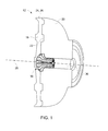
FIG. 1 is a perspective view of a region of a compressor section of a gas turbine system; -
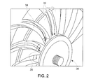
FIG. 2 is a perspective view of an air manipulation device disposed within a rear wheel of the compressor section; -
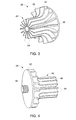
FIG. 3 is a rear perspective view of the air manipulation device; -
FIG. 4 is a side perspective view of the air manipulation device; -
FIG. 5 is an elevational, cross-sectional view of the air manipulation device disposed between a front wheel and the rear wheel; -
FIG. 6 is a schematic view of smooth airflow transition into a center bore of the rear wheel; -
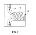
FIG. 7 is a schematic view of swirling airflow transition into the center bore of the rear wheel; -
FIG. 8 is a perspective view of an embodiment of the air manipulation device attaching to the front wheel; and -
FIG. 9 is a perspective view of another embodiment of the air manipulation device attaching to the front wheel. - The detailed description explains embodiments of the invention, together with advantages and features, by way of example with reference to the drawings.
- Referring to
FIGS. 1 and2 , a gas turbine system 10 includes acompressor section 12 comprising a plurality of wheels for accelerating airflow through the gas turbine system and into a combustor section (not illustrated). The last two wheels that the airflow passes through are referred to as afront wheel 18 andrear wheel 20, respectively. In a common gas turbine system, thecompressor section 12 may include a plurality of wheels which includes two rear wheels, thereby making thefront wheel 18 correspond to the second to last wheel and therear wheel 20 correspond to the rearmost wheel. Irrespective of the precise number of wheels disposed within thecompressor section 12, the wheels referenced are with respect to the last two wheels of thecompressor section 12. - The
front wheel 18 and therear wheel 20 are disposed within thecompressor section 12 in a manner that forms anaxial gap 22 between the two wheels, with thegap 22 extending radially inward from an outer radial location 24 that corresponds substantially to an outer diameter 26 of at least one of thewheels gap 22 is configured to allow airflow from the outer radial location 24 toward acenter axis 28 that extends axially through acenter bore 30 of therear wheel 20. The airflow passes through the center bore 30 and towards a turbine section containing a plurality of turbine wheels. Although the aforementioned description relates to thefront wheel 18 and therear wheel 20 being disposed within thecompressor section 12, it is to be understood that the wheels referred to may be disposed anywhere in the gas turbine system 10, including but not limited to the turbine section 16. - The rear wheel includes a plurality of
impellers 32 that define at least oneimpeller slot 34. The number ofimpeller slots 34 is a function of howmany impellers 32 are present, with eachimpeller slot 34 defined by adjacent pairs ofimpellers 32. Theimpeller slots 34 extend radially inward from a location proximate the outer radial location 24 toward thecenter bore 30 and may take on a curved configuration, as defined by the geometry of theimpellers 32. Typically, theimpeller slots 34 will extend to a location proximate aninlet 35 of the center bore 30. Eachimpeller 32 extends axially forward, or upstream, to directly contact or come in close contact with thefront wheel 18. In the case of theimpellers 32 directly contacting or abutting thefront wheel 18, the airflow is solely transferred radially inward through theimpeller slots 34. - Referring now to
FIGS. 3 and 4 , anairflow manipulation device 36 having abase portion 38 and avane portion 40 is disposed between thefront wheel 18 and therear wheel 20. Thebase portion 38 is substantially circular with anouter base diameter 42, but it is conceivable that other geometries may be employed. Thebase portion 38 is disposed to directly abut or come closely in contact with thefront wheel 18. Thevane portion 40 includes at least one, and typically a plurality ofvanes 44 that extend from thebase portion 38 axially rearward and into the center bore 30. Thevanes 44 may extend radially inward as well, as thevanes 44 extend axially rearward into the center bore 30. Thevanes 44 are aligned in such a manner that disposes a portion of thevanes 44 within theimpeller slots 34, thereby imposing an extension of theimpeller slots 34 directly into thecenter bore 30. Specifically, thevanes 44 form a plurality ofvane slots 46 that function to serve as extensions of theimpeller slots 34, such that airflow rushing radially inward through theimpeller slots 34 smoothly transitions into thevane slots 46, and thereby the center bore 30. Alternatively, thevanes 44 may be adjustable, such that thevanes 44 extend to various regions, including up to or in to theimpeller slots 34. - Referring to
FIGS. 5-7 , the effect of theairflow manipulation device 36, and more specifically thevane slots 46, is illustrated. A smooth deflection and transition of the airflow rushing inward toward thecenter bore 30 is established by the interaction of thevanes 44 and theimpeller slots 34. This is in contrast to airflow that converts to aswirling vortex 48 in a system that does not extendvanes 44 into the center bore 30 (FIG. 9 ). Reduction of such swirling airflow advantageously reduces the pressure drop of the airflow as it passes into thecenter bore 30. - Referring now to
FIGS. 8 and9 , attachment of theairflow manipulation device 36 to thecompressor section 12 may be facilitated in a number of ways. As described above, it is to be appreciated that theairflow manipulation device 36 and the associatedwheels compressor section 12. A first embodiment includes a threadedfastener 50 that extends rearward from thebase portion 38 of theairflow manipulation device 36. Thefront wheel 18 includes a corresponding threadedportion 52 that is configured to matably receive the threadedfastener 50, and thereby theairflow manipulation device 36. Another embodiment includes acenter aperture 54 extending axially throughout theairflow manipulation device 36 and sized to receive amechanical fastener 56, such as a stud therein. Themechanical fastener 56 includes arear flange 58 that engages a region of theairflow manipulation device 36 proximate thecenter aperture 54 at a rearward location. Additionally, the front of themechanical fastener 56 includes a threaded portion that matably engages the corresponding threadedportion 52 of thefront wheel 18. The aforementioned embodiments are merely exemplary structures that facilitate attaching theairflow manipulation device 36 and it is conceivable that several other fasteners may be employed. For example, even press fit or interference fit ofbase portion 38 into thefront wheel 18 can be used to secure theflow manipulation device 36 into place. - While the invention has been described in detail in connection with only a limited number of embodiments, it should be readily understood that the invention is not limited to such disclosed embodiments. Rather, the invention can be modified to incorporate any number of variations, alterations, substitutions or equivalent arrangements not heretofore described, but which are commensurate with the spirit and scope of the invention. Additionally, while various embodiments of the invention have been described, it is to be understood that aspects of the invention may include only some of the described embodiments. Accordingly, the invention is not to be seen as limited by the foregoing description, but is only limited by the scope of the appended claims.
Claims (11)
- A gas turbine system (10) having a compressor section (12), a combustor section and a turbine section, comprising:a first wheel (18);a second wheel (20) having a center bore (30) extending axially therethrough, wherein the first wheel (18) and the second wheel (20) are relatively adjacent each other;a gap (22) disposed between the first wheel (18) and the second wheel (20), wherein airflow is directed radially inward within the gap (22) toward the center bore (30) of the second wheel (20); andan airflow manipulation device (36) disposed within the gap (22) and at least partially extending into the center bore (30), wherein the airflow manipulation device (36) includes at least one vane (44) extending axially into the center bore (30).
- The gas turbine system of claim 1, wherein the second wheel (20) is located axially rearward of the first wheel (18).
- The gas turbine system of claim 1 or 2, wherein at least one of the first wheel (18) and the second wheel (20) includes a plurality of impeller blades (32) defining a plurality of impeller slots (34).
- The gas turbine system of any of claims 1 to 3, the airflow manipulation device (36) comprising:a base portion (38) having an outer diameter (42); anda vane portion (40) that includes a plurality of vanes (44).
- The gas turbine system of claim 4, wherein the plurality of vanes (44) extend from proximate the outer diameter (42) of the base portion (38) radially inward and axially rearward into the center bore (30).
- The gas turbine system of claim 4 or 5, wherein at least one of the plurality of vanes (44) adjustably extends up to or in to one of the plurality of impeller slots (34).
- The gas turbine system of any preceding claim, wherein the airflow manipulation device (36) is operably coupled to the first wheel (18).
- The gas turbine system of claim 7, wherein the airflow manipulation device (36) is fixed directly to the first wheel (18).
- The gas turbine system of claim 7, wherein the airflow manipulation device is indirectly coupled to the first wheel (18) by a mechanical fastener (56).
- The gas turbine system of any preceding claim, wherein the first wheel (18) and the second wheel (20) are disposed within the compressor section (12).
- The gas turbine system of any of claims 1 to 9, wherein the first wheel (18) and the second wheel (20) are disposed within the turbine section.
Applications Claiming Priority (1)
| Application Number | Priority Date | Filing Date | Title |
|---|---|---|---|
| US13/365,685 US20130199207A1 (en) | 2012-02-03 | 2012-02-03 | Gas turbine system |
Publications (2)
| Publication Number | Publication Date |
|---|---|
| EP2628897A2 true EP2628897A2 (en) | 2013-08-21 |
| EP2628897A3 EP2628897A3 (en) | 2015-12-16 |
Family
ID=47631334
Family Applications (1)
| Application Number | Title | Priority Date | Filing Date |
|---|---|---|---|
| EP13152940.6A Withdrawn EP2628897A3 (en) | 2012-02-03 | 2013-01-28 | Gas turbine system |
Country Status (5)
| Country | Link |
|---|---|
| US (1) | US20130199207A1 (en) |
| EP (1) | EP2628897A3 (en) |
| JP (1) | JP2013160232A (en) |
| CN (1) | CN103244269A (en) |
| RU (1) | RU2013104194A (en) |
Cited By (2)
| Publication number | Priority date | Publication date | Assignee | Title |
|---|---|---|---|---|
| WO2016072998A1 (en) * | 2014-11-07 | 2016-05-12 | General Electric Company | Compressor bleed passage with auxiliary impeller in an axial shaft bore |
| EP3199755A1 (en) * | 2016-01-27 | 2017-08-02 | Ansaldo Energia Switzerland AG | Anti-vortex structure for a gas turbine |
Families Citing this family (4)
| Publication number | Priority date | Publication date | Assignee | Title |
|---|---|---|---|---|
| EP2826957A1 (en) * | 2013-07-17 | 2015-01-21 | Siemens Aktiengesellschaft | Rotor for a thermal turbomachine |
| EP2826958A1 (en) * | 2013-07-17 | 2015-01-21 | Siemens Aktiengesellschaft | Rotor for a thermal flow engine |
| KR102184778B1 (en) * | 2013-12-19 | 2020-11-30 | 한화에어로스페이스 주식회사 | Swirler for gas turbine |
| CN112360761A (en) * | 2021-01-12 | 2021-02-12 | 中国航发上海商用航空发动机制造有限责任公司 | Centripetal pressurization air entraining device and system |
Family Cites Families (11)
| Publication number | Priority date | Publication date | Assignee | Title |
|---|---|---|---|---|
| US2618433A (en) * | 1948-06-23 | 1952-11-18 | Curtiss Wright Corp | Means for bleeding air from compressors |
| US3311344A (en) * | 1964-12-08 | 1967-03-28 | John V Yost | Turbine wheel |
| US4541774A (en) * | 1980-05-01 | 1985-09-17 | General Electric Company | Turbine cooling air deswirler |
| FR2552164B1 (en) * | 1983-09-21 | 1986-12-26 | Snecma | COMPRESSOR DISC WITH INTEGRATED CENTRIPTIC ACCELERATOR FOR SUCTION OF AIR IN A GAS TURBINE COOLING DEVICE |
| GB2217393B (en) * | 1988-04-14 | 1992-07-08 | Rolls Royce Plc | Nose bullet anti-icing for gas turbine engines |
| US6398487B1 (en) * | 2000-07-14 | 2002-06-04 | General Electric Company | Methods and apparatus for supplying cooling airflow in turbine engines |
| JP4675638B2 (en) * | 2005-02-08 | 2011-04-27 | 本田技研工業株式会社 | Secondary air supply device for gas turbine engine |
| US20080141677A1 (en) * | 2006-12-15 | 2008-06-19 | Siemens Power Generation, Inc. | Axial tangential radial on-board cooling air injector for a gas turbine |
| US7708519B2 (en) * | 2007-03-26 | 2010-05-04 | Honeywell International Inc. | Vortex spoiler for delivery of cooling airflow in a turbine engine |
| US8453463B2 (en) * | 2009-05-27 | 2013-06-04 | Pratt & Whitney Canada Corp. | Anti-vortex device for a gas turbine engine compressor |
| US8348599B2 (en) * | 2010-03-26 | 2013-01-08 | General Electric Company | Turbine rotor wheel |
-
2012
- 2012-02-03 US US13/365,685 patent/US20130199207A1/en not_active Abandoned
-
2013
- 2013-01-28 EP EP13152940.6A patent/EP2628897A3/en not_active Withdrawn
- 2013-02-01 JP JP2013017984A patent/JP2013160232A/en active Pending
- 2013-02-01 CN CN2013100428344A patent/CN103244269A/en active Pending
- 2013-02-01 RU RU2013104194/06A patent/RU2013104194A/en not_active Application Discontinuation
Non-Patent Citations (1)
| Title |
|---|
| None |
Cited By (3)
| Publication number | Priority date | Publication date | Assignee | Title |
|---|---|---|---|---|
| WO2016072998A1 (en) * | 2014-11-07 | 2016-05-12 | General Electric Company | Compressor bleed passage with auxiliary impeller in an axial shaft bore |
| CN107076165A (en) * | 2014-11-07 | 2017-08-18 | 通用电气公司 | The compressor bleed air path with auxiliary movable vane in axial axis bore |
| EP3199755A1 (en) * | 2016-01-27 | 2017-08-02 | Ansaldo Energia Switzerland AG | Anti-vortex structure for a gas turbine |
Also Published As
| Publication number | Publication date |
|---|---|
| EP2628897A3 (en) | 2015-12-16 |
| RU2013104194A (en) | 2014-08-10 |
| US20130199207A1 (en) | 2013-08-08 |
| JP2013160232A (en) | 2013-08-19 |
| CN103244269A (en) | 2013-08-14 |
Similar Documents
| Publication | Publication Date | Title |
|---|---|---|
| EP2628897A2 (en) | Gas turbine system | |
| US7862295B2 (en) | Device for guiding a stream of air entering a combustion chamber of a turbomachine | |
| EP2256299A2 (en) | Deflector for a gas turbine strut and vane assembly | |
| EP2357366A1 (en) | Heat exchange module for vehicle and vehicle with same | |
| US8882443B2 (en) | Turbomachine compressor with an air injection system | |
| US20170292536A1 (en) | Return stage of a multi-stage turbocompressor or turboexpander having rough wall surfaces | |
| US10815789B2 (en) | Impingement holes for a turbine engine component | |
| CN110966261B (en) | Gas-entraining structure and method for casing of gas compressor and aircraft engine | |
| US10533458B2 (en) | Turbine ventilation structure | |
| US10151206B2 (en) | Turbomachine, circulation structure and method | |
| JP2011226286A (en) | Turbine stationary blade of gas turbine | |
| US20130129498A1 (en) | Diffuser, in particular for an axial flow machine | |
| US20160123236A1 (en) | Compressor and gas turbine | |
| US20200011206A1 (en) | Steam turbine exhaust chamber and steam turbine | |
| US9903382B2 (en) | Axial compressor for fluid-flow machines | |
| US20120027578A1 (en) | Systems and apparatus relating to diffusers in combustion turbine engines | |
| EP2261567B1 (en) | Gas turbine and method of forming insertion hole for combustor of gas turbine | |
| US20170321606A1 (en) | Airflow manipulation device for compressor | |
| US9546600B2 (en) | Nozzle having an orifice plug for a gas turbomachine | |
| US8591179B2 (en) | Axial-flow compressor with a flow pulse generator | |
| CN112576321A (en) | Outflow region of a turbine of an exhaust-gas turbocharger | |
| EP3156602B1 (en) | Airfoil for axial flow machine | |
| EP2615263A2 (en) | Diffuser for a gas turbine | |
| JP2014234729A (en) | Centrifugal compressor and gas turbine engine | |
| GB2497420A (en) | Turbine blade cooling |
Legal Events
| Date | Code | Title | Description |
|---|---|---|---|
| PUAI | Public reference made under article 153(3) epc to a published international application that has entered the european phase |
Free format text: ORIGINAL CODE: 0009012 |
|
| AK | Designated contracting states |
Kind code of ref document: A2 Designated state(s): AL AT BE BG CH CY CZ DE DK EE ES FI FR GB GR HR HU IE IS IT LI LT LU LV MC MK MT NL NO PL PT RO RS SE SI SK SM TR |
|
| AX | Request for extension of the european patent |
Extension state: BA ME |
|
| PUAL | Search report despatched |
Free format text: ORIGINAL CODE: 0009013 |
|
| AK | Designated contracting states |
Kind code of ref document: A3 Designated state(s): AL AT BE BG CH CY CZ DE DK EE ES FI FR GB GR HR HU IE IS IT LI LT LU LV MC MK MT NL NO PL PT RO RS SE SI SK SM TR |
|
| AX | Request for extension of the european patent |
Extension state: BA ME |
|
| RIC1 | Information provided on ipc code assigned before grant |
Ipc: F01D 5/08 20060101AFI20151110BHEP Ipc: F01D 25/12 20060101ALI20151110BHEP |
|
| STAA | Information on the status of an ep patent application or granted ep patent |
Free format text: STATUS: THE APPLICATION IS DEEMED TO BE WITHDRAWN |
|
| 18D | Application deemed to be withdrawn |
Effective date: 20160617 |