EP2628679A2 - Control system for reconfigurable rotary wing aircraft - Google Patents
Control system for reconfigurable rotary wing aircraft Download PDFInfo
- Publication number
- EP2628679A2 EP2628679A2 EP13155177.2A EP13155177A EP2628679A2 EP 2628679 A2 EP2628679 A2 EP 2628679A2 EP 13155177 A EP13155177 A EP 13155177A EP 2628679 A2 EP2628679 A2 EP 2628679A2
- Authority
- EP
- European Patent Office
- Prior art keywords
- module
- control system
- constraints
- mode
- aircraft
- Prior art date
- Legal status (The legal status is an assumption and is not a legal conclusion. Google has not performed a legal analysis and makes no representation as to the accuracy of the status listed.)
- Granted
Links
Images

Classifications
-
- G—PHYSICS
- G05—CONTROLLING; REGULATING
- G05D—SYSTEMS FOR CONTROLLING OR REGULATING NON-ELECTRIC VARIABLES
- G05D1/00—Control of position, course, altitude or attitude of land, water, air or space vehicles, e.g. using automatic pilots
- G05D1/08—Control of attitude, i.e. control of roll, pitch, or yaw
- G05D1/0808—Control of attitude, i.e. control of roll, pitch, or yaw specially adapted for aircraft
- G05D1/0858—Control of attitude, i.e. control of roll, pitch, or yaw specially adapted for aircraft specially adapted for vertical take-off of aircraft
Definitions
- the subject matter disclosed herein relates generally to control systems, and in particular to a control system for a reconfigurable rotary wing aircraft.
- Vehicles such as rotary wing aircraft, typically employ a control system that receives operator commands and interfaces those commands to components of the aircraft.
- a control system that receives operator commands and interfaces those commands to components of the aircraft.
- existing rotary wing aircraft may employ a primary flight control system (PFCS) and an automatic flight control system (AFCS) that receive operator commands and control aircraft operation.
- PFCS primary flight control system
- AFCS automatic flight control system
- These control systems also sense vehicle status to provide feedback and improve control of the rotary wing aircraft.
- a given control system may have a plurality of goals and a plurality of limits.
- Limits are inequality constraints on system dynamic variables.
- An example limit may be to prevent an engine temperature from exceeding a certain temperature in order to prevent meltdown or rapid deterioration.
- An example goal may be to achieve a certain engine thrust level, such as a thrust of 10,000 pounds. While it is desirable to achieve goals, it is necessary to meet limits.
- a multivariable system may include a number of effectors that can be adjusted to meet system goals and limits. In some cases, a system may be cross-coupled, which means that each effector change may affect goals and limits with varying dynamics.
- Model predictive control is a multivariable control theory that explicitly includes limits and, therefore, provides a good match with practical systems. MPC can also be configured to respond in realtime to changes in the system, such as actuator faults. Thus, MPC provides a formal method of control algorithm design for multivariable systems that can decouple responses, as well as physically possible, even as limits are hit and faults occur.
- One embodiment is a control system for a rotary wing aircraft having a reconfigurable element.
- the control system includes a model predictive control module receiving operator commands, objectives and constraints; and a dynamic inversion module receiving an output of the model predictive control module, the dynamic inversion module providing control commands to reconfigure the reconfigurable element of the rotary wing aircraft.
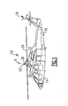
- FIG. 1 illustrates and exemplary rotary wing aircraft
- FIG. 2 depicts a control system in an exemplary embodiment.
- FIG. 1 schematically illustrates a rotary wing aircraft 10 having a main rotor assembly 12.
- the aircraft 10 includes an airframe 14 having an extending tail 16 which mounts a tail rotor system 18, such as an anti-torque system, a translational thrust system, a pusher propeller, a rotor propulsion system, and the like.
- the main rotor assembly 12 is driven about an axis of rotation R through a main gearbox (illustrated schematically at 20) by one or more engines 22.
- the main rotor assembly 12 includes a multiple of rotor blades 24 mounted to a rotor hub 26.
- helicopter configuration is illustrated and described in the disclosed embodiment, other configurations and/or machines, such as high speed compound rotary wing aircraft with supplemental translational thrust systems, dual contra-rotating, coaxial rotor system aircraft, turbo-props, tilt-rotors and tilt-wing aircraft, will also benefit from embodiments of the invention.
- the rotary wing aircraft 10 may include reconfigurable elements.
- Rotary wing aircraft performance and mission effectiveness can be increased by including reconfigurable or "adaptive" elements which allow the vehicle characteristics to be tailored to specific tasks.
- These reconfigurable elements include a variety of technologies which can be switched and combined such that certain flying characteristics can be enhanced.
- the reconfigurable elements when selectively activated based on mission requirements, may, for example, increase maximum rotor blade 24 lift, suppress characteristics such as vibration and/or noise, increase flight speed, improve hover performance at high gross weights, increase maneuverability, or the like.
- An on-blade reconfigurable element typically enhances one or two rotor attributes such as low noise, low vibration, efficiency, maneuverability, payload, or speed.
- the reconfigurable elements can be turned on or off as the mission segment requires.
- the reconfigurable elements are also designed to work synergistically to maximize rotor capabilities.
- Reconfigurable elements also provide an inherent control redundancy.
- the switching and combining of reconfigurable elements can occur both rapidly (rotor time scale) and slowly (between missions) since changing flight conditions dictate continually changing priorities.
- Embodiments described herein provide a control system architecture which insures acceptable flying qualities for rotorcraft while simultaneously arbitrating between competing requirements to determine the optimal allocation of control resources. Also, this control system can re-distribute control commands following system failures when redundant control surfaces are available.
- the control system is responsible for managing the reconfigurable elements while providing acceptable flying qualities for the vehicle.
- the control system provides several functions which are useful for implementing reconfigurable elements, namely: system stability, robustness, constraint avoidance, technology arbitration, and mission mode switching.
- FIG. 2 depicts a control system 100 in an exemplary embodiment.
- the control system may be implemented by a microprocessor-based controller executing software code stored in a storage medium to implement the functions described herein.
- Control system 10 may also be implemented in hardware, or a combination of hardware and software.
- the control system 100 may be implemented as part of a flight control system present in the rotary wing aircraft 10. It is understood that many of the functions of the flight control system are not shown in FIG. 2 for ease of description of embodiments of the invention.
- Operator commands 102 are provided as inputs to the control system 100.
- Operator commands 102 include commands from a pilot, in a manned aircraft, which may include pilot inceptor inputs, and activation of various buttons and switches. Alternatively, operator commands 102 may come from another control system if the aircraft is unmanned.
- Operator commands 102 may also include a mode selection for the rotary wing aircraft 10.
- the aircraft modes relate to the aircraft task, such as attack/scout mode, stealth mode, speed mode, utility mode, cargo mode, etc.
- the aircraft modes may also include day and night versions for each mode. Further, each aircraft mode may include one or more sub-modes that identify a desired operating characteristic such as controlling vibration, reducing acoustic noise, using minimal power, providing maximum maneuverability, providing damage compensation, etc.
- An active operating mode module 104 receives operator commands and determines the desired aircraft operational mode and sub-mode (if any).
- the active operating mode module 104 may identity the aircraft mode based on a mode/sub-mode selection command from the operator commands 102.
- the active operating mode module 104 can automatically select a mode/sub-mode based on operator commands, without a mode/sub-mode selection command. For example, if the operator commands include arming weapons systems, the active operating mode module 104 switches the aircraft mode to a combat mode, without requiring an express mode selection.
- Constraint compatibility module 106 determines constraints on aircraft operation in response to the mode/sub-mode from the active operating mode module 104. These constraints associated with the modes/sub-modes are parsed using predetermined compatibility criteria, which make binary selections between competing constraints.
- a constraint selection and prioritization module 108 determines the constraints that will be applied to model predictive control (MPC) module 110.
- the constraints are assembled in constraint selection and prioritization module 108 as a set of primary, secondary, and global constraints and passed to the MPC module 110. Assembly of the constraints at frequent intervals allows for dynamic reconfiguration with rapidly changing conditions.
- the constraint selection and prioritization module 108 prioritizes the variety of aircraft constraints in order of importance. In the case of conflicting constraints, constraints are first divided into hard and soft constraints. Hard constraints are critical constraints which cannot be relaxed; only soft-constraints are relaxed. Within the category of soft constraints, each constraint is assigned a priority which determines the amount by which the soft constraint is relaxed relative to other constraints.
- Objective selection module 112 translates the operator commands into predetermined objectives and prioritizes the objectives in order of importance. Objectives are prioritized in module 112 using finite-state logic and variable weightings (fixed and adaptive) based on operator commands, current flight conditions, and predetermined precedence criteria. The mode/sub-mode selections are mapped to scheduled models in objective selection module 112, and all models are assembled and passed to the MPC module 110.
- control system 100 supports the translation of operator commands including mission mode, as well as sub-modes, into a set of objectives and constraints for the MPC module 110 which best preserve handling qualities and aircraft safety.
- the operator commands may select modes and sub-modes. These modes are converted to objective functions and constraints which capture the best handling tradeoffs for the mode/sub-mode.
- MPC module 110 receives the operator commands 102, constraints from constraint selection module 106 and objectives from objective selection module 112, to predict aircraft response.
- MPC module 110 employs model-based feed forward and feedback control, as shown at 114.
- MPC module 110 uses feed-forward command shaping and tailors the commands to avoid the applicable system constraints. MPC module 110 accomplishes this function by continuously solving an optimization problem so that the operator commands 102 are followed as closely as possible without violating the system constraints.
- Dynamic inversion module 116 generates control commands for the reconfigurable aircraft 118. This includes reconfigurable elements (e.g., mission adaptive rotor elements) and other components (e.g., swashplate).
- the dynamic inversion module 116 provides control allocation when redundant effectors are present and allows for adaptation of the control allocation in the event of failure.
- the dynamic inversion module 116 also provides the feedback stabilization over a wide range of operating conditions.
- the dynamic inversion module 116 is used to maintain stability properties in accordance with expected changes in aircraft configuration.
- the dynamic inversion module 116 focuses on capturing and canceling the dominant aircraft dynamics with low order aircraft models, but also has the flexibility to target specific higher-order modes for inversion. These include, for example, variable rotor modes which change with varying rotor speed configurations.
- the hybrid, adaptive flight control system 100 composed of both dynamic inversion and model predictive control strategies, has advantages over existing model-following, dynamic inversion, and model predictive control strategies.
- This hybrid control system 100 combines the benefits of each of the architectures while compensating for their weaknesses.
- Control system 100 takes advantage of model-predictive control's capability of integrating system constraints into the control algorithm providing the benefit of anticipation of, and compensation for, system constraints.
- Control system 100 also has the ability to dynamically change objectives and constraints in real time. Control system 100 does not suffer from the disadvantages of pure MPC architectures, such as stability guarantees and computation overhead requirements.
- the ability to dynamically change constraints and generate a control command to avoid this constraint is an inherent weakness of both model following and dynamic inversion, when used individually.
- Control system 100 also takes advantage of dynamic inversion's partition of an inner loop designed for stability and robustness, and an outer loop designed for handling qualities. Also, control system 100 has consistent plant dynamics for all flight conditions eliminating the need for controller gain scheduling, which is a weakness of model-following control architectures. Another benefit of control system 100, derived from the dynamic inversion module 116, is the plant dynamics are reduced to an integrator which has ideal gain and phase margins. This is an advantage over both pure model-following and MPC architectures.
- hybrid control system 100 can arbitrate between competing objectives to enhance vehicle capabilities and avoid system constraints, while maintaining stability.
- Control system 100 is beneficial for rotorcraft utilizing mission adaptive rotors and redundant control surfaces, or for rotorcraft which undergo significant aircraft state changes either due to physical configuration changes or aerodynamic effects.
- the MPC module 110 is used in parallel with a backup command model in case of unexpected solver infeasibility.
Landscapes
- Engineering & Computer Science (AREA)
- Aviation & Aerospace Engineering (AREA)
- Radar, Positioning & Navigation (AREA)
- Remote Sensing (AREA)
- Physics & Mathematics (AREA)
- General Physics & Mathematics (AREA)
- Automation & Control Theory (AREA)
- Feedback Control In General (AREA)
- Control Of Position, Course, Altitude, Or Attitude Of Moving Bodies (AREA)
Abstract
Description
- The subject matter disclosed herein relates generally to control systems, and in particular to a control system for a reconfigurable rotary wing aircraft.
- Vehicles, such as rotary wing aircraft, typically employ a control system that receives operator commands and interfaces those commands to components of the aircraft. For example, existing rotary wing aircraft may employ a primary flight control system (PFCS) and an automatic flight control system (AFCS) that receive operator commands and control aircraft operation. These control systems also sense vehicle status to provide feedback and improve control of the rotary wing aircraft.
- A given control system may have a plurality of goals and a plurality of limits. Limits are inequality constraints on system dynamic variables. An example limit may be to prevent an engine temperature from exceeding a certain temperature in order to prevent meltdown or rapid deterioration. Another might be to prevent a rotor speed from exceeding a certain angular velocity to maintain structural integrity and aircraft control power. An example goal may be to achieve a certain engine thrust level, such as a thrust of 10,000 pounds. While it is desirable to achieve goals, it is necessary to meet limits. A multivariable system may include a number of effectors that can be adjusted to meet system goals and limits. In some cases, a system may be cross-coupled, which means that each effector change may affect goals and limits with varying dynamics. In a cross-coupled system, it is not possible to change a single effector in isolation to affect only a single goal or limit, as a change in one effector may affect a plurality of goals or limits. Calculating effector commands in a cross-coupled multivariable system can therefore be complex and computationally demanding.
- Model predictive control (MPC) is a multivariable control theory that explicitly includes limits and, therefore, provides a good match with practical systems. MPC can also be configured to respond in realtime to changes in the system, such as actuator faults. Thus, MPC provides a formal method of control algorithm design for multivariable systems that can decouple responses, as well as physically possible, even as limits are hit and faults occur.
- One embodiment is a control system for a rotary wing aircraft having a reconfigurable element. The control system includes a model predictive control module receiving operator commands, objectives and constraints; and a dynamic inversion module receiving an output of the model predictive control module, the dynamic inversion module providing control commands to reconfigure the reconfigurable element of the rotary wing aircraft.
- Other aspects, features, and techniques of the invention will become more apparent from the following description taken in conjunction with the drawings.
Further embodiments of the invention are set out in the following numbered paragraphs: - 1. A control system for a rotary wing aircraft having a reconfigurable element, the control system comprising:
- a model predictive control module receiving operator commands, objectives and constraints; and
- a dynamic inversion module receiving an output of the model predictive control module, the dynamic inversion module providing control commands to reconfigure the reconfigurable element of the rotary wing aircraft.
- 2. The control system of paragraph 1 further comprising:
- an active operating mode module receiving operator commands and determining an aircraft mode in response to the operator commands;
- wherein the output of the model predictive control module is dependent upon the aircraft mode.
- 3. The control system of paragraph 2 wherein:
- the aircraft mode includes a sub-mode.
- 4. The control system of paragraph 2 wherein:
- the active operating mode module identifies the aircraft mode based on a mode/sub-mode selection command.
- 5. The control system of paragraph 2 further comprising:
- a constraint compatibility module for determining the constraints on aircraft operation in response to the aircraft mode; and
- a constraint selection and prioritization module for prioritizing the constraints in order of importance.
- 6. The control system of paragraph 5 wherein:
- the constraint compatibility module parses constraints using predetermined compatibility criteria to make binary selections between competing constraints.
- 7. The control system of paragraph 5 wherein:
- the constraint selection and prioritization module divides the constraints into hard and soft constraints, wherein hard constraints are constraints which cannot be relaxed.
- 8. The control system of paragraph 7 wherein:
- each soft constraint is assigned a priority to determine an amount by which a soft constraint is relaxed relative to other constraints, the constraint selection and prioritization module providing the constraints to the model predictive control module.
- 9. The control system of paragraph 5 further comprising:
- an objective selection module for translating the operator commands into predetermined objectives and prioritizing the objectives in order of importance.
- 10. The control system of paragraph 9 wherein:
- the objective selection module prioritizes objectives using finite-state logic and variable weightings.
- 11. The control system of paragraph 1 wherein:
- the model predictive control module includes model-based feed forward and feedback control.
- 12. The control system of paragraph 1 wherein:
- the dynamic inversion module provides control allocation to redundant effectors for the reconfigurable element.
- Referring now to the drawings wherein like elements are numbered alike in the several FIGURES, in which:
-
FIG. 1 illustrates and exemplary rotary wing aircraft; and -
FIG. 2 depicts a control system in an exemplary embodiment. -
FIG. 1 schematically illustrates a rotary wing aircraft 10 having amain rotor assembly 12. The aircraft 10 includes anairframe 14 having an extending tail 16 which mounts a tail rotor system 18, such as an anti-torque system, a translational thrust system, a pusher propeller, a rotor propulsion system, and the like. Themain rotor assembly 12 is driven about an axis of rotation R through a main gearbox (illustrated schematically at 20) by one ormore engines 22. Themain rotor assembly 12 includes a multiple ofrotor blades 24 mounted to arotor hub 26. Although a particular helicopter configuration is illustrated and described in the disclosed embodiment, other configurations and/or machines, such as high speed compound rotary wing aircraft with supplemental translational thrust systems, dual contra-rotating, coaxial rotor system aircraft, turbo-props, tilt-rotors and tilt-wing aircraft, will also benefit from embodiments of the invention. - The rotary wing aircraft 10 may include reconfigurable elements. Rotary wing aircraft performance and mission effectiveness can be increased by including reconfigurable or "adaptive" elements which allow the vehicle characteristics to be tailored to specific tasks. These reconfigurable elements include a variety of technologies which can be switched and combined such that certain flying characteristics can be enhanced. The reconfigurable elements, when selectively activated based on mission requirements, may, for example, increase
maximum rotor blade 24 lift, suppress characteristics such as vibration and/or noise, increase flight speed, improve hover performance at high gross weights, increase maneuverability, or the like. An on-blade reconfigurable element typically enhances one or two rotor attributes such as low noise, low vibration, efficiency, maneuverability, payload, or speed. The reconfigurable elements can be turned on or off as the mission segment requires. The reconfigurable elements are also designed to work synergistically to maximize rotor capabilities. - Reconfigurable elements also provide an inherent control redundancy. The switching and combining of reconfigurable elements can occur both rapidly (rotor time scale) and slowly (between missions) since changing flight conditions dictate continually changing priorities. Embodiments described herein provide a control system architecture which insures acceptable flying qualities for rotorcraft while simultaneously arbitrating between competing requirements to determine the optimal allocation of control resources. Also, this control system can re-distribute control commands following system failures when redundant control surfaces are available.
- The control system is responsible for managing the reconfigurable elements while providing acceptable flying qualities for the vehicle. The reconfigurable element enabling technologies, while enhancing the vehicle capabilities, also greatly expands the operating conditions over which stability and robustness are controlled by the control system. The control system provides several functions which are useful for implementing reconfigurable elements, namely: system stability, robustness, constraint avoidance, technology arbitration, and mission mode switching.
-
FIG. 2 depicts a control system 100 in an exemplary embodiment. The control system may be implemented by a microprocessor-based controller executing software code stored in a storage medium to implement the functions described herein. Control system 10 may also be implemented in hardware, or a combination of hardware and software. The control system 100 may be implemented as part of a flight control system present in the rotary wing aircraft 10. It is understood that many of the functions of the flight control system are not shown inFIG. 2 for ease of description of embodiments of the invention. - Operator commands 102 are provided as inputs to the control system 100. Operator commands 102 include commands from a pilot, in a manned aircraft, which may include pilot inceptor inputs, and activation of various buttons and switches. Alternatively, operator commands 102 may come from another control system if the aircraft is unmanned. Operator commands 102 may also include a mode selection for the rotary wing aircraft 10. The aircraft modes relate to the aircraft task, such as attack/scout mode, stealth mode, speed mode, utility mode, cargo mode, etc. The aircraft modes may also include day and night versions for each mode. Further, each aircraft mode may include one or more sub-modes that identify a desired operating characteristic such as controlling vibration, reducing acoustic noise, using minimal power, providing maximum maneuverability, providing damage compensation, etc.
- An active
operating mode module 104 receives operator commands and determines the desired aircraft operational mode and sub-mode (if any). The activeoperating mode module 104 may identity the aircraft mode based on a mode/sub-mode selection command from the operator commands 102. Alternatively, the activeoperating mode module 104 can automatically select a mode/sub-mode based on operator commands, without a mode/sub-mode selection command. For example, if the operator commands include arming weapons systems, the activeoperating mode module 104 switches the aircraft mode to a combat mode, without requiring an express mode selection. - The aircraft mode determined by active
operating mode module 104 is provided toconstraint compatibility module 106.Constraint compatibility module 106 determines constraints on aircraft operation in response to the mode/sub-mode from the activeoperating mode module 104. These constraints associated with the modes/sub-modes are parsed using predetermined compatibility criteria, which make binary selections between competing constraints. - Once the applicable constraints are identified, a constraint selection and
prioritization module 108 determines the constraints that will be applied to model predictive control (MPC)module 110. The constraints are assembled in constraint selection andprioritization module 108 as a set of primary, secondary, and global constraints and passed to theMPC module 110. Assembly of the constraints at frequent intervals allows for dynamic reconfiguration with rapidly changing conditions. The constraint selection andprioritization module 108 prioritizes the variety of aircraft constraints in order of importance. In the case of conflicting constraints, constraints are first divided into hard and soft constraints. Hard constraints are critical constraints which cannot be relaxed; only soft-constraints are relaxed. Within the category of soft constraints, each constraint is assigned a priority which determines the amount by which the soft constraint is relaxed relative to other constraints. -
Objective selection module 112 translates the operator commands into predetermined objectives and prioritizes the objectives in order of importance. Objectives are prioritized inmodule 112 using finite-state logic and variable weightings (fixed and adaptive) based on operator commands, current flight conditions, and predetermined precedence criteria. The mode/sub-mode selections are mapped to scheduled models inobjective selection module 112, and all models are assembled and passed to theMPC module 110. - Through the
constraint selection module 106 andobjective selection module 112, control system 100 supports the translation of operator commands including mission mode, as well as sub-modes, into a set of objectives and constraints for theMPC module 110 which best preserve handling qualities and aircraft safety. As noted above, the operator commands may select modes and sub-modes. These modes are converted to objective functions and constraints which capture the best handling tradeoffs for the mode/sub-mode. -
MPC module 110 receives the operator commands 102, constraints fromconstraint selection module 106 and objectives fromobjective selection module 112, to predict aircraft response.MPC module 110 employs model-based feed forward and feedback control, as shown at 114.MPC module 110 uses feed-forward command shaping and tailors the commands to avoid the applicable system constraints.MPC module 110 accomplishes this function by continuously solving an optimization problem so that the operator commands 102 are followed as closely as possible without violating the system constraints. -
Dynamic inversion module 116 generates control commands for thereconfigurable aircraft 118. This includes reconfigurable elements (e.g., mission adaptive rotor elements) and other components (e.g., swashplate). Thedynamic inversion module 116 provides control allocation when redundant effectors are present and allows for adaptation of the control allocation in the event of failure. Thedynamic inversion module 116 also provides the feedback stabilization over a wide range of operating conditions. Thedynamic inversion module 116 is used to maintain stability properties in accordance with expected changes in aircraft configuration. Thedynamic inversion module 116 focuses on capturing and canceling the dominant aircraft dynamics with low order aircraft models, but also has the flexibility to target specific higher-order modes for inversion. These include, for example, variable rotor modes which change with varying rotor speed configurations. - The hybrid, adaptive flight control system 100, composed of both dynamic inversion and model predictive control strategies, has advantages over existing model-following, dynamic inversion, and model predictive control strategies. This hybrid control system 100 combines the benefits of each of the architectures while compensating for their weaknesses. Control system 100 takes advantage of model-predictive control's capability of integrating system constraints into the control algorithm providing the benefit of anticipation of, and compensation for, system constraints. Control system 100 also has the ability to dynamically change objectives and constraints in real time. Control system 100 does not suffer from the disadvantages of pure MPC architectures, such as stability guarantees and computation overhead requirements. The ability to dynamically change constraints and generate a control command to avoid this constraint is an inherent weakness of both model following and dynamic inversion, when used individually.
- Control system 100 also takes advantage of dynamic inversion's partition of an inner loop designed for stability and robustness, and an outer loop designed for handling qualities. Also, control system 100 has consistent plant dynamics for all flight conditions eliminating the need for controller gain scheduling, which is a weakness of model-following control architectures. Another benefit of control system 100, derived from the
dynamic inversion module 116, is the plant dynamics are reduced to an integrator which has ideal gain and phase margins. This is an advantage over both pure model-following and MPC architectures. - By combining the benefits of
MPC module 110 anddynamic inversion module 116, and compensating their weakness, hybrid control system 100 can arbitrate between competing objectives to enhance vehicle capabilities and avoid system constraints, while maintaining stability. Control system 100 is beneficial for rotorcraft utilizing mission adaptive rotors and redundant control surfaces, or for rotorcraft which undergo significant aircraft state changes either due to physical configuration changes or aerodynamic effects. Additionally, theMPC module 110 is used in parallel with a backup command model in case of unexpected solver infeasibility. - The terminology used herein is for the purpose of describing particular embodiments only and is not intended to be limiting of the invention. While the description of the present invention has been presented for purposes of illustration and description, it is not intended to be exhaustive or limited to the invention in the form disclosed. Many modifications, variations, alterations, substitutions, or equivalent arrangement not hereto described will be apparent to those of ordinary skill in the art without departing from the scope and spirit of the invention. Additionally, while various embodiment of the invention have been described, it is to be understood that aspects of the invention may include only some of the described embodiments. Accordingly, the invention is not to be seen as limited by the foregoing description, but is only limited by the scope of the appended claims.
Claims (12)
- A control system for a rotary wing aircraft having a reconfigurable element, the control system comprising:a model predictive control module receiving operator commands, objectives and constraints; anda dynamic inversion module receiving an output of the model predictive control module, the dynamic inversion module providing control commands to reconfigure the reconfigurable element of the rotary wing aircraft.
- The control system of claim 1 further comprising:an active operating mode module receiving operator commands and determining an aircraft mode in response to the operator commands;wherein the output of the model predictive control module is dependent upon the aircraft mode.
- The control system of claim 2 wherein:the aircraft mode includes a sub-mode.
- The control system of claim 2 or 3 wherein:the active operating mode module identifies the aircraft mode based on a mode/sub-mode selection command.
- The control system of any of claims 2 to 4 further comprising:a constraint compatibility module for determining the constraints on aircraft operation in response to the aircraft mode; anda constraint selection and prioritization module for prioritizing the constraints in order of importance.
- The control system of claim 5 wherein:the constraint compatibility module parses constraints using predetermined compatibility criteria to make binary selections between competing constraints.
- The control system of claim 5 or 6 wherein:the constraint selection and prioritization module divides the constraints into hard and soft constraints, wherein hard constraints are constraints which cannot be relaxed.
- The control system of claim 7 wherein:each soft constraint is assigned a priority to determine an amount by which a soft constraint is relaxed relative to other constraints, the constraint selection and prioritization module providing the constraints to the model predictive control module.
- The control system of any of the preceding claims further comprising:an objective selection module for translating the operator commands into predetermined objectives and prioritizing the objectives in order of importance.
- The control system of claim 9 wherein:the objective selection module prioritizes objectives using finite-state logic and variable weightings.
- The control system of any of the preceding claims wherein:the model predictive control module includes model-based feed forward and feedback control.
- The control system of any of the preceding claims wherein:the dynamic inversion module provides control allocation to redundant effectors for the reconfigurable element.
Applications Claiming Priority (1)
| Application Number | Priority Date | Filing Date | Title |
|---|---|---|---|
| US13/396,769 US10025320B2 (en) | 2012-02-15 | 2012-02-15 | Control system for reconfigurable rotary wing aircraft |
Publications (3)
| Publication Number | Publication Date |
|---|---|
| EP2628679A2 true EP2628679A2 (en) | 2013-08-21 |
| EP2628679A3 EP2628679A3 (en) | 2018-01-03 |
| EP2628679B1 EP2628679B1 (en) | 2019-06-12 |
Family
ID=47843049
Family Applications (1)
| Application Number | Title | Priority Date | Filing Date |
|---|---|---|---|
| EP13155177.2A Active EP2628679B1 (en) | 2012-02-15 | 2013-02-14 | Control system for reconfigurable rotary wing aircraft |
Country Status (2)
| Country | Link |
|---|---|
| US (1) | US10025320B2 (en) |
| EP (1) | EP2628679B1 (en) |
Cited By (1)
| Publication number | Priority date | Publication date | Assignee | Title |
|---|---|---|---|---|
| CN108958258A (en) * | 2018-07-25 | 2018-12-07 | 吉林大学 | A kind of track follow-up control method, control system and the relevant apparatus of unmanned vehicle |
Families Citing this family (17)
| Publication number | Priority date | Publication date | Assignee | Title |
|---|---|---|---|---|
| US9494925B2 (en) * | 2011-12-20 | 2016-11-15 | United Technologies Corporation | Hybrid control system |
| US9317042B2 (en) * | 2014-01-28 | 2016-04-19 | Sikorsky Aircraft Corporation | Pitch feedback control splitting for helicopters with redundant actuators |
| US9429952B2 (en) * | 2014-04-04 | 2016-08-30 | Sikorsky Aircraft Corporation | Rotorcraft control laws for sea-based operations |
| US9747543B1 (en) * | 2014-09-30 | 2017-08-29 | Hrl Laboratories, Llc | System and method for controller adaptation |
| WO2016200457A2 (en) * | 2015-03-23 | 2016-12-15 | Sikorsky Aircraft Corporation | Aerial vehicle including autonomous rotor speed control |
| CN105739513B (en) * | 2016-02-05 | 2018-06-12 | 北京航空航天大学 | A kind of quadrotor flying robot nonlinear loci tracking control unit and its tracking and controlling method |
| CN107065897B (en) * | 2016-06-20 | 2019-12-24 | 浙江工业大学 | Explicit model predictive control method for a three-degree-of-freedom helicopter |
| US10831192B1 (en) * | 2016-09-20 | 2020-11-10 | Piasecki Aircraft Corporation | Control system for an aircraft |
| US20180114199A1 (en) * | 2016-10-24 | 2018-04-26 | Sikorsky Aircraft Corporation | Task sharing and scheduling interface |
| US10759528B2 (en) * | 2016-11-15 | 2020-09-01 | Sikorsky Aircraft Corporation | Model following control for torque and rotor speed |
| US10189559B2 (en) * | 2016-11-22 | 2019-01-29 | Sikorsky Aircraft Corporation | Rotor speed control using a feed-forward rotor speed command |
| CN108873862B (en) * | 2018-06-15 | 2021-06-29 | 上海航天控制技术研究所 | Comprehensive evaluation method for stability of control system of aircraft |
| CN109062237B (en) * | 2018-09-17 | 2021-07-20 | 南京航空航天大学 | Active disturbance rejection attitude control method for unmanned tiltrotor aircraft |
| JP7528923B2 (en) * | 2019-03-20 | 2024-08-06 | 日本電気株式会社 | Unmanned aircraft control system, method, and program |
| CN109946971B (en) * | 2019-04-04 | 2021-09-24 | 南京航空航天大学 | A smooth switching control method for the transition section of a tilt-rotor UAV |
| CN116774729A (en) * | 2023-06-27 | 2023-09-19 | 哈尔滨工业大学(深圳)(哈尔滨工业大学深圳科技创新研究院) | Overdrive rotor unmanned aerial vehicle and adaptive predictive control method thereof |
| CN117647925B (en) * | 2024-01-30 | 2024-04-09 | 成都正扬博创电子技术有限公司 | Redundancy flight control calculation method, device, equipment and storage medium |
Family Cites Families (14)
| Publication number | Priority date | Publication date | Assignee | Title |
|---|---|---|---|---|
| US5141177A (en) * | 1991-08-28 | 1992-08-25 | United Technologies Corporation | Model following control system |
| US5238203A (en) * | 1991-08-28 | 1993-08-24 | United Technologies Corporation | High speed turn coordination for rotary wing aircraft |
| US5213283A (en) * | 1991-08-28 | 1993-05-25 | United Technologies Corporation | Low speed turn coordination for rotary wing aircraft |
| US5446666A (en) * | 1994-05-17 | 1995-08-29 | The Boeing Company | Ground state-fly state transition control for unique-trim aircraft flight control system |
| US6932569B2 (en) | 2002-05-17 | 2005-08-23 | Sikorsky Aircraft Corporation | Active control of multi-element rotor blade airfoils |
| US6882889B2 (en) * | 2002-12-02 | 2005-04-19 | United Technologies Corporation | Constrained dynamic inversion control algorithm |
| US7328074B2 (en) | 2002-12-02 | 2008-02-05 | United Technologies Corporation | Real-time quadratic programming for control of dynamical systems |
| US20060235584A1 (en) * | 2005-04-14 | 2006-10-19 | Honeywell International Inc. | Decentralized maneuver control in heterogeneous autonomous vehicle networks |
| US20080125880A1 (en) * | 2006-07-31 | 2008-05-29 | Kahn Aaron D | Method and apparatus for an adaptive control system |
| US7438259B1 (en) | 2006-08-16 | 2008-10-21 | Piasecki Aircraft Corporation | Compound aircraft control system and method |
| US7970498B2 (en) * | 2007-06-01 | 2011-06-28 | Sikorsky Aircraft Corporation | Model based sensor system for loads aware control laws |
| US8185255B2 (en) | 2007-11-30 | 2012-05-22 | The Boeing Company | Robust control effector allocation |
| US7949416B2 (en) | 2008-05-06 | 2011-05-24 | United Technologies Corporation | Multivariable control system |
| US8145329B2 (en) * | 2009-06-02 | 2012-03-27 | Honeywell International Inc. | Method and system for combining feedback and feedforward in model predictive control |
-
2012
- 2012-02-15 US US13/396,769 patent/US10025320B2/en active Active
-
2013
- 2013-02-14 EP EP13155177.2A patent/EP2628679B1/en active Active
Non-Patent Citations (1)
| Title |
|---|
| None |
Cited By (2)
| Publication number | Priority date | Publication date | Assignee | Title |
|---|---|---|---|---|
| CN108958258A (en) * | 2018-07-25 | 2018-12-07 | 吉林大学 | A kind of track follow-up control method, control system and the relevant apparatus of unmanned vehicle |
| CN108958258B (en) * | 2018-07-25 | 2021-06-25 | 吉林大学 | Track following control method, control system and related device for unmanned vehicle |
Also Published As
| Publication number | Publication date |
|---|---|
| EP2628679A3 (en) | 2018-01-03 |
| EP2628679B1 (en) | 2019-06-12 |
| US20130206899A1 (en) | 2013-08-15 |
| US10025320B2 (en) | 2018-07-17 |
Similar Documents
| Publication | Publication Date | Title |
|---|---|---|
| EP2628679B1 (en) | Control system for reconfigurable rotary wing aircraft | |
| EP2296064B1 (en) | Life improving flight control system | |
| US11235860B2 (en) | Control inceptor management system | |
| US11649038B2 (en) | Hybrid electric powerplant (HEP) control architecture | |
| EP3162713B1 (en) | Power leveling controller | |
| EP3357810B1 (en) | Power demand anticipation systems for rotorcraft | |
| EP2170700B1 (en) | Fly-by-wire flight control system with electronic lead/lag damper algorithm | |
| CN108502196B (en) | Reverse haptic cues for rotorcraft rotor overspeed protection | |
| Mazeh et al. | Fault-tolerant control of an hexarotor unmanned aerial vehicle applying outdoor tests and experiments | |
| US9771145B2 (en) | Rotorcraft fly-by-wire control laws | |
| US9567091B2 (en) | System and method for maximizing aircraft safe landing capability during one engine inoperative operation | |
| EP3249587A1 (en) | Task allocation and variable autonomy levels | |
| US9429952B2 (en) | Rotorcraft control laws for sea-based operations | |
| CA2904282A1 (en) | Method and system for model based control for variable pitch fan engines and turbo-shaft, turbo-propeller engines | |
| US20180348794A1 (en) | System and Method for Controlling Rotorcraft Load Priority | |
| Tang et al. | Prognostics-enhanced automated contingency management for advanced autonomous systems | |
| US9174730B2 (en) | Automated rotating tail rotor control | |
| CN110498038A (en) | Rotorcraft and its control method | |
| Kai | Full-envelope flight control for compound vertical takeoff and landing aircraft | |
| Landis et al. | Advanced flight control research and development at Boeing Helicopters | |
| US12291326B2 (en) | Supplemental engine power control | |
| US11247782B2 (en) | System and method for controlling rotorcraft | |
| Arnold et al. | Closed loop IBC results from CH-53G flight tests | |
| Chamseddine et al. | Control allocation for a modified quadrotor helicopter based on reliability analysis | |
| Rajendran et al. | Fault tolerant control of a small helicopter with Tail Rotor Failures in hovering mode |
Legal Events
| Date | Code | Title | Description |
|---|---|---|---|
| PUAI | Public reference made under article 153(3) epc to a published international application that has entered the european phase |
Free format text: ORIGINAL CODE: 0009012 |
|
| AK | Designated contracting states |
Kind code of ref document: A2 Designated state(s): AL AT BE BG CH CY CZ DE DK EE ES FI FR GB GR HR HU IE IS IT LI LT LU LV MC MK MT NL NO PL PT RO RS SE SI SK SM TR |
|
| AX | Request for extension of the european patent |
Extension state: BA ME |
|
| PUAL | Search report despatched |
Free format text: ORIGINAL CODE: 0009013 |
|
| AK | Designated contracting states |
Kind code of ref document: A3 Designated state(s): AL AT BE BG CH CY CZ DE DK EE ES FI FR GB GR HR HU IE IS IT LI LT LU LV MC MK MT NL NO PL PT RO RS SE SI SK SM TR |
|
| AX | Request for extension of the european patent |
Extension state: BA ME |
|
| RIC1 | Information provided on ipc code assigned before grant |
Ipc: B64C 17/00 20060101AFI20171128BHEP Ipc: B64C 27/00 20060101ALI20171128BHEP |
|
| STAA | Information on the status of an ep patent application or granted ep patent |
Free format text: STATUS: REQUEST FOR EXAMINATION WAS MADE |
|
| 17P | Request for examination filed |
Effective date: 20180627 |
|
| RBV | Designated contracting states (corrected) |
Designated state(s): AL AT BE BG CH CY CZ DE DK EE ES FI FR GB GR HR HU IE IS IT LI LT LU LV MC MK MT NL NO PL PT RO RS SE SI SK SM TR |
|
| RIC1 | Information provided on ipc code assigned before grant |
Ipc: B64C 17/00 20060101AFI20180924BHEP Ipc: G05D 1/08 20060101ALI20180924BHEP Ipc: B64C 27/00 20060101ALI20180924BHEP |
|
| GRAP | Despatch of communication of intention to grant a patent |
Free format text: ORIGINAL CODE: EPIDOSNIGR1 |
|
| STAA | Information on the status of an ep patent application or granted ep patent |
Free format text: STATUS: GRANT OF PATENT IS INTENDED |
|
| INTG | Intention to grant announced |
Effective date: 20181219 |
|
| GRAS | Grant fee paid |
Free format text: ORIGINAL CODE: EPIDOSNIGR3 |
|
| GRAA | (expected) grant |
Free format text: ORIGINAL CODE: 0009210 |
|
| STAA | Information on the status of an ep patent application or granted ep patent |
Free format text: STATUS: THE PATENT HAS BEEN GRANTED |
|
| AK | Designated contracting states |
Kind code of ref document: B1 Designated state(s): AL AT BE BG CH CY CZ DE DK EE ES FI FR GB GR HR HU IE IS IT LI LT LU LV MC MK MT NL NO PL PT RO RS SE SI SK SM TR |
|
| REG | Reference to a national code |
Ref country code: GB Ref legal event code: FG4D |
|
| REG | Reference to a national code |
Ref country code: CH Ref legal event code: EP |
|
| REG | Reference to a national code |
Ref country code: AT Ref legal event code: REF Ref document number: 1142221 Country of ref document: AT Kind code of ref document: T Effective date: 20190615 |
|
| REG | Reference to a national code |
Ref country code: DE Ref legal event code: R096 Ref document number: 602013056397 Country of ref document: DE |
|
| REG | Reference to a national code |
Ref country code: IE Ref legal event code: FG4D |
|
| REG | Reference to a national code |
Ref country code: NL Ref legal event code: MP Effective date: 20190612 |
|
| REG | Reference to a national code |
Ref country code: LT Ref legal event code: MG4D |
|
| PG25 | Lapsed in a contracting state [announced via postgrant information from national office to epo] |
Ref country code: FI Free format text: LAPSE BECAUSE OF FAILURE TO SUBMIT A TRANSLATION OF THE DESCRIPTION OR TO PAY THE FEE WITHIN THE PRESCRIBED TIME-LIMIT Effective date: 20190612 Ref country code: LT Free format text: LAPSE BECAUSE OF FAILURE TO SUBMIT A TRANSLATION OF THE DESCRIPTION OR TO PAY THE FEE WITHIN THE PRESCRIBED TIME-LIMIT Effective date: 20190612 Ref country code: ES Free format text: LAPSE BECAUSE OF FAILURE TO SUBMIT A TRANSLATION OF THE DESCRIPTION OR TO PAY THE FEE WITHIN THE PRESCRIBED TIME-LIMIT Effective date: 20190612 Ref country code: HR Free format text: LAPSE BECAUSE OF FAILURE TO SUBMIT A TRANSLATION OF THE DESCRIPTION OR TO PAY THE FEE WITHIN THE PRESCRIBED TIME-LIMIT Effective date: 20190612 Ref country code: AL Free format text: LAPSE BECAUSE OF FAILURE TO SUBMIT A TRANSLATION OF THE DESCRIPTION OR TO PAY THE FEE WITHIN THE PRESCRIBED TIME-LIMIT Effective date: 20190612 Ref country code: SE Free format text: LAPSE BECAUSE OF FAILURE TO SUBMIT A TRANSLATION OF THE DESCRIPTION OR TO PAY THE FEE WITHIN THE PRESCRIBED TIME-LIMIT Effective date: 20190612 Ref country code: NO Free format text: LAPSE BECAUSE OF FAILURE TO SUBMIT A TRANSLATION OF THE DESCRIPTION OR TO PAY THE FEE WITHIN THE PRESCRIBED TIME-LIMIT Effective date: 20190912 |
|
| PG25 | Lapsed in a contracting state [announced via postgrant information from national office to epo] |
Ref country code: GR Free format text: LAPSE BECAUSE OF FAILURE TO SUBMIT A TRANSLATION OF THE DESCRIPTION OR TO PAY THE FEE WITHIN THE PRESCRIBED TIME-LIMIT Effective date: 20190913 Ref country code: LV Free format text: LAPSE BECAUSE OF FAILURE TO SUBMIT A TRANSLATION OF THE DESCRIPTION OR TO PAY THE FEE WITHIN THE PRESCRIBED TIME-LIMIT Effective date: 20190612 Ref country code: RS Free format text: LAPSE BECAUSE OF FAILURE TO SUBMIT A TRANSLATION OF THE DESCRIPTION OR TO PAY THE FEE WITHIN THE PRESCRIBED TIME-LIMIT Effective date: 20190612 Ref country code: BG Free format text: LAPSE BECAUSE OF FAILURE TO SUBMIT A TRANSLATION OF THE DESCRIPTION OR TO PAY THE FEE WITHIN THE PRESCRIBED TIME-LIMIT Effective date: 20190912 |
|
| REG | Reference to a national code |
Ref country code: AT Ref legal event code: MK05 Ref document number: 1142221 Country of ref document: AT Kind code of ref document: T Effective date: 20190612 |
|
| PG25 | Lapsed in a contracting state [announced via postgrant information from national office to epo] |
Ref country code: RO Free format text: LAPSE BECAUSE OF FAILURE TO SUBMIT A TRANSLATION OF THE DESCRIPTION OR TO PAY THE FEE WITHIN THE PRESCRIBED TIME-LIMIT Effective date: 20190612 Ref country code: SK Free format text: LAPSE BECAUSE OF FAILURE TO SUBMIT A TRANSLATION OF THE DESCRIPTION OR TO PAY THE FEE WITHIN THE PRESCRIBED TIME-LIMIT Effective date: 20190612 Ref country code: PT Free format text: LAPSE BECAUSE OF FAILURE TO SUBMIT A TRANSLATION OF THE DESCRIPTION OR TO PAY THE FEE WITHIN THE PRESCRIBED TIME-LIMIT Effective date: 20191014 Ref country code: CZ Free format text: LAPSE BECAUSE OF FAILURE TO SUBMIT A TRANSLATION OF THE DESCRIPTION OR TO PAY THE FEE WITHIN THE PRESCRIBED TIME-LIMIT Effective date: 20190612 Ref country code: AT Free format text: LAPSE BECAUSE OF FAILURE TO SUBMIT A TRANSLATION OF THE DESCRIPTION OR TO PAY THE FEE WITHIN THE PRESCRIBED TIME-LIMIT Effective date: 20190612 Ref country code: NL Free format text: LAPSE BECAUSE OF FAILURE TO SUBMIT A TRANSLATION OF THE DESCRIPTION OR TO PAY THE FEE WITHIN THE PRESCRIBED TIME-LIMIT Effective date: 20190612 Ref country code: EE Free format text: LAPSE BECAUSE OF FAILURE TO SUBMIT A TRANSLATION OF THE DESCRIPTION OR TO PAY THE FEE WITHIN THE PRESCRIBED TIME-LIMIT Effective date: 20190612 |
|
| PG25 | Lapsed in a contracting state [announced via postgrant information from national office to epo] |
Ref country code: IT Free format text: LAPSE BECAUSE OF FAILURE TO SUBMIT A TRANSLATION OF THE DESCRIPTION OR TO PAY THE FEE WITHIN THE PRESCRIBED TIME-LIMIT Effective date: 20190612 Ref country code: SM Free format text: LAPSE BECAUSE OF FAILURE TO SUBMIT A TRANSLATION OF THE DESCRIPTION OR TO PAY THE FEE WITHIN THE PRESCRIBED TIME-LIMIT Effective date: 20190612 Ref country code: IS Free format text: LAPSE BECAUSE OF FAILURE TO SUBMIT A TRANSLATION OF THE DESCRIPTION OR TO PAY THE FEE WITHIN THE PRESCRIBED TIME-LIMIT Effective date: 20191012 |
|
| REG | Reference to a national code |
Ref country code: DE Ref legal event code: R097 Ref document number: 602013056397 Country of ref document: DE |
|
| PG25 | Lapsed in a contracting state [announced via postgrant information from national office to epo] |
Ref country code: TR Free format text: LAPSE BECAUSE OF FAILURE TO SUBMIT A TRANSLATION OF THE DESCRIPTION OR TO PAY THE FEE WITHIN THE PRESCRIBED TIME-LIMIT Effective date: 20190612 |
|
| PLBE | No opposition filed within time limit |
Free format text: ORIGINAL CODE: 0009261 |
|
| STAA | Information on the status of an ep patent application or granted ep patent |
Free format text: STATUS: NO OPPOSITION FILED WITHIN TIME LIMIT |
|
| PG25 | Lapsed in a contracting state [announced via postgrant information from national office to epo] |
Ref country code: DK Free format text: LAPSE BECAUSE OF FAILURE TO SUBMIT A TRANSLATION OF THE DESCRIPTION OR TO PAY THE FEE WITHIN THE PRESCRIBED TIME-LIMIT Effective date: 20190612 Ref country code: PL Free format text: LAPSE BECAUSE OF FAILURE TO SUBMIT A TRANSLATION OF THE DESCRIPTION OR TO PAY THE FEE WITHIN THE PRESCRIBED TIME-LIMIT Effective date: 20190612 |
|
| 26N | No opposition filed |
Effective date: 20200313 |
|
| PG25 | Lapsed in a contracting state [announced via postgrant information from national office to epo] |
Ref country code: SI Free format text: LAPSE BECAUSE OF FAILURE TO SUBMIT A TRANSLATION OF THE DESCRIPTION OR TO PAY THE FEE WITHIN THE PRESCRIBED TIME-LIMIT Effective date: 20190612 Ref country code: IS Free format text: LAPSE BECAUSE OF FAILURE TO SUBMIT A TRANSLATION OF THE DESCRIPTION OR TO PAY THE FEE WITHIN THE PRESCRIBED TIME-LIMIT Effective date: 20200224 |
|
| PG2D | Information on lapse in contracting state deleted |
Ref country code: IS |
|
| REG | Reference to a national code |
Ref country code: CH Ref legal event code: PL |
|
| REG | Reference to a national code |
Ref country code: BE Ref legal event code: MM Effective date: 20200229 |
|
| PG25 | Lapsed in a contracting state [announced via postgrant information from national office to epo] |
Ref country code: LU Free format text: LAPSE BECAUSE OF NON-PAYMENT OF DUE FEES Effective date: 20200214 Ref country code: MC Free format text: LAPSE BECAUSE OF FAILURE TO SUBMIT A TRANSLATION OF THE DESCRIPTION OR TO PAY THE FEE WITHIN THE PRESCRIBED TIME-LIMIT Effective date: 20190612 |
|
| PG25 | Lapsed in a contracting state [announced via postgrant information from national office to epo] |
Ref country code: LI Free format text: LAPSE BECAUSE OF NON-PAYMENT OF DUE FEES Effective date: 20200229 Ref country code: CH Free format text: LAPSE BECAUSE OF NON-PAYMENT OF DUE FEES Effective date: 20200229 |
|
| PG25 | Lapsed in a contracting state [announced via postgrant information from national office to epo] |
Ref country code: IE Free format text: LAPSE BECAUSE OF NON-PAYMENT OF DUE FEES Effective date: 20200214 |
|
| PG25 | Lapsed in a contracting state [announced via postgrant information from national office to epo] |
Ref country code: BE Free format text: LAPSE BECAUSE OF NON-PAYMENT OF DUE FEES Effective date: 20200229 |
|
| PG25 | Lapsed in a contracting state [announced via postgrant information from national office to epo] |
Ref country code: MT Free format text: LAPSE BECAUSE OF FAILURE TO SUBMIT A TRANSLATION OF THE DESCRIPTION OR TO PAY THE FEE WITHIN THE PRESCRIBED TIME-LIMIT Effective date: 20190612 Ref country code: CY Free format text: LAPSE BECAUSE OF FAILURE TO SUBMIT A TRANSLATION OF THE DESCRIPTION OR TO PAY THE FEE WITHIN THE PRESCRIBED TIME-LIMIT Effective date: 20190612 |
|
| PG25 | Lapsed in a contracting state [announced via postgrant information from national office to epo] |
Ref country code: MK Free format text: LAPSE BECAUSE OF FAILURE TO SUBMIT A TRANSLATION OF THE DESCRIPTION OR TO PAY THE FEE WITHIN THE PRESCRIBED TIME-LIMIT Effective date: 20190612 |
|
| P01 | Opt-out of the competence of the unified patent court (upc) registered |
Effective date: 20230519 |
|
| PGFP | Annual fee paid to national office [announced via postgrant information from national office to epo] |
Ref country code: DE Payment date: 20250227 Year of fee payment: 13 |
|
| PGFP | Annual fee paid to national office [announced via postgrant information from national office to epo] |
Ref country code: FR Payment date: 20250225 Year of fee payment: 13 |
|
| PGFP | Annual fee paid to national office [announced via postgrant information from national office to epo] |
Ref country code: GB Payment date: 20250227 Year of fee payment: 13 |