EP2628404A1 - Slide fastener, top stop for slide fasteners and slide fastener production method - Google Patents
Slide fastener, top stop for slide fasteners and slide fastener production method Download PDFInfo
- Publication number
- EP2628404A1 EP2628404A1 EP10858391.5A EP10858391A EP2628404A1 EP 2628404 A1 EP2628404 A1 EP 2628404A1 EP 10858391 A EP10858391 A EP 10858391A EP 2628404 A1 EP2628404 A1 EP 2628404A1
- Authority
- EP
- European Patent Office
- Prior art keywords
- fastener
- storage
- decorative part
- stopper
- body unit
- Prior art date
- Legal status (The legal status is an assumption and is not a legal conclusion. Google has not performed a legal analysis and makes no representation as to the accuracy of the status listed.)
- Granted
Links
Images




Classifications
-
- A—HUMAN NECESSITIES
- A44—HABERDASHERY; JEWELLERY
- A44B—BUTTONS, PINS, BUCKLES, SLIDE FASTENERS, OR THE LIKE
- A44B19/00—Slide fasteners
- A44B19/24—Details
- A44B19/36—Means for permanently uniting the stringers at the end; Means for stopping movement of slider at the end
-
- A—HUMAN NECESSITIES
- A41—WEARING APPAREL
- A41D—OUTERWEAR; PROTECTIVE GARMENTS; ACCESSORIES
- A41D27/00—Details of garments or of their making
- A41D27/08—Trimmings; Ornaments
-
- A—HUMAN NECESSITIES
- A44—HABERDASHERY; JEWELLERY
- A44B—BUTTONS, PINS, BUCKLES, SLIDE FASTENERS, OR THE LIKE
- A44B19/00—Slide fasteners
- A44B19/02—Slide fasteners with a series of separate interlocking members secured to each stringer tape
-
- A—HUMAN NECESSITIES
- A44—HABERDASHERY; JEWELLERY
- A44B—BUTTONS, PINS, BUCKLES, SLIDE FASTENERS, OR THE LIKE
- A44B19/00—Slide fasteners
- A44B19/24—Details
-
- A—HUMAN NECESSITIES
- A44—HABERDASHERY; JEWELLERY
- A44B—BUTTONS, PINS, BUCKLES, SLIDE FASTENERS, OR THE LIKE
- A44B19/00—Slide fasteners
- A44B19/24—Details
- A44B19/26—Sliders
- A44B19/262—Pull members; Ornamental attachments for sliders
-
- A—HUMAN NECESSITIES
- A44—HABERDASHERY; JEWELLERY
- A44B—BUTTONS, PINS, BUCKLES, SLIDE FASTENERS, OR THE LIKE
- A44B19/00—Slide fasteners
- A44B19/42—Making by processes not fully provided for in one other class, e.g. B21D53/50, B21F45/18, B22D17/16, B29D5/00
Definitions
- the present invention relates to a slide fastener, and more particularly relates to a slide fastener in which decorative parts are arranged on configuration members of the slide fastener, and a top stopper for the slide fastener, and a method of producing the slide fastener.
- a slider In a slide fastener, a slider is inserted into left and right element chains that are attached to tape side edges opposite to a pair of left and right fastener tapes, and since the slider is slid along the element chains, the element chains are engaged or separated.
- decorative parts are arranged on the surfaces of fastener elements and the like, and decoration property is given to improve its esthetic appearance.
- Japanese Patent No. 3176936 discloses an element to which the decoration property is given.
- the above patent describes that concave grooves are formed on the surface of the element, and decoration stones are fitted onto the concave grooves.
- Patent Document 1 Japanese Patent No. 3176936
- the present invention provides a slide fastener in which a decorative part and a slide fastener configuration member can be connected stronger and the design level is improved, a top stopper for the slide fastener, and a method of producing the slide fastener.
- a slide fastener which includes: a pair of fastener tapes; chains of fastener elements arranged along opposing tape side edges of the fastener tapes; a slider for engaging and separating the fastener elements; a bottom stopper arranged at one ends of the chains of the fastener elements on the pair of fastener tapes; and a pair of top stoppers arranged at the other ends of the chains of the fastener elements
- the slide fastener includes: a concave storage provided on a surface of at least one of the fastener elements, the slider, the bottom stopper and the top stoppers; a decorative part stored in the storage; and a fixer, which is formed integrally with the storage and protrudes from the storage and fixes the decorative part in the storage.
- the decorative part includes a body unit, a surface exposure portion, and a maximum diameter portion whose cross-section has a maximum diameter of the decorative part and defines a boundary between the body unit and the surface exposure portion, wherein the body unit is positioned lower than the maximum diameter portion and the surface exposure portion is tapered upwardly from the body unit, wherein the maximum diameter portion of the decorative part is fixed to inside the storage so as to be arranged lower than the surface of the fastener elements, the slider, the bottom stopper or the top stoppers where the decorative part is arranged.
- the decorative part includes a body unit, a surface exposure portion, and a maximum diameter portion whose cross-section has a maximum diameter of the decorative part and defines a boundary between the body unit and the surface exposure portion, wherein the body unit is positioned lower than the maximum diameter portion and the surface exposure portion is tapered upwardly from the body unit, wherein a top surface of the surface exposure portion of the decorative part is fixed to inside the storage so as to be located on the same flat surface as the surface of the fastener elements, the slider, the bottom stopper or the top stoppers or located lower than the surface.
- the decorative part includes a body unit, a surface exposure portion, and a maximum diameter portion whose cross-section has a maximum diameter of the decorative part and defines a boundary between the body unit and the surface exposure portion, wherein the body unit is positioned lower than the maximum diameter portion and the surface exposure portion is tapered upwardly from the body unit, wherein the storage includes a first groove which stores the body unit and a second groove connected to the first groove above the first groove and stores the surface exposure portion, and wherein the fixer is expansively protruded from a side wall of the second groove and covers a part of the surface exposure portion.
- a length in a lateral direction of the fastener tapes embedded in the fastener elements or the top stoppers is 50 % or less of the maximum diameter of the storage.
- the fastener tapes are arranged away from a center of the storage so that the fastener tapes are not embedded on a central axis of the storage.
- a top stopper for a slide fastener encompassing: a first top stopper made of resin which includes a concave first storage which is arranged on a tape side edge of a first fastener tape and formed on a surface, a first decorative part stored in the first storage, and a first fixer that is integrated with the first storage and protrudes from the first storage and fixes the first decorative part; a second top stopper which includes a concave second storage which is arranged on a tape side edge of a second fastener tape opposite to the first fastener tape and formed on the surface, a second decorative part stored in the second storage, and a second fixer which is integrated with the second storage and protrudes from the second storage and fixes the second decorative part; and a stopper, which is arranged on the tape side edge and located opposite to the fastener element located closest to the side of the first top stopper in the chains of the fastener elements arranged along the tape side edge of the first fastener tape and formed integrally with
- a center of the first top stopper is arranged so as to be shifted to a side of the second fastener tape from a tip of the first fastener tape embedded in the first top stopper, and a center of the second top stopper is arranged to be shifted to a side of the first fastener tape from a tip of the second fastener tape embedded in the second top stopper.
- the present invention provides, in still another aspect, a method of producing a slide fastener which includes a pair of fastener tapes; chains of fastener elements arranged along opposing tape side edges of the fastener tapes; a slider for engaging and separating the fastener elements; a bottom stopper arranged at one ends of the chains of the fastener elements on the pair of fastener tapes; and a pair of top stoppers arranged at the other ends of the chains of the fastener elements, the method includes: a step of forming a concave storage on a surface of at least one of the fastener elements, the slider, the bottom stopper and the top stoppers; a step of storing a decorative part in the storage; and a step of partially melting a part of the storage and forming a fixer protruding into the storage and fixing the decorative part to inside the storage by using the fixer.
- the step of partially melting the part of the storage and forming the fixer protruding into the storage includes a step of applying supersonic vibration to the storage and melting a part of the storage.
- the slide fastener in which the decorative part and the slide fastener configuration member can be connected more strongly and the design level is improved, and the top stoppers for the slide fastener, and the method of producing the slide fastener.
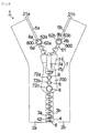
- a slide fastener 1 includes: a pair of fastener tapes 2a, 2b; chains of fastener elements 3a, 3b arranged along opposing tape side edges 21a, 21b of the fastener tapes 2a, 2b; a slider 7 for engaging and separating the fastener elements 3a, 3b; a bottom stopper 4 arranged to straddle the pair of fastener tapes 2a, 2b at one ends of the chains of the fastener elements 3a, 3b; and a pair of top stoppers 6a, 6b arranged at the other ends of the chains of the fastener elements 3a, 3b.
- one ends of the chains of the fastener elements 3a, 3b refers to ends on the sides that face a direction in which the slide fastener 1 is opened when the slider 7 is slid in the longitudinal direction of the fastener tapes 2a, 2b.
- the other ends of the chains of the fastener elements 3a, 3b refers to ends on the side that face a direction in which the slide fastener 1 is closed when the slider 7 is slid in the longitudinal direction of the fastener tapes 2a, 2b.
- a front-rear direction of the fastener tapes 2a, 2b is defined as "an upper-lower direction” or "a height (depth) direction”. That is, this embodiment is described under an assumption that the front surface side of the fastener tapes 2a, 2b is defined as “an upper portion” and the rear surface side of the fastener tapes 2a, 2b is defined as "a lower portion”.
- fastener tapes 2a, 2b For the fastener tapes 2a, 2b, a band-shaped material that is woven or knitted from synthetic fiber or natural fiber is used, and cores 5a, 5b are arranged along tape side edges 21a, 21b extending in the longitudinal direction.
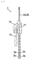
- the fastener elements 3a, 3b are shaped substantially symmetric with respect to the front and rear surfaces of the fastener tapes 2a, 2b, with the fastener tapes 2a, 2b as centers, as shown in Fig. 2 .
- the fastener element 3b includes a base 35 fixed onto the fastener tape 2b, a neck 36 protruding from the base 35 to the side of the opposite fastener tape 2a, and an engagement head 37 further expanding to the side of the fastener tape 2a from the neck 36. Since the slider 7 shown in Fig. 1 is slid from one ends to the other ends of the chains of the fastener elements 3a, 3b, the chains of the fastener elements 3a, 3b can be engaged or separated.
- the slider 7 includes: a slider body 71 which accommodates the fastener elements 3a, 3b therein so that the fastener elements 3a, 3b are engaged or separated; a puller holder 74 arranged on the surface of the slider body 71; and a puller 75 supported by the puller holder 74.
- the bottom stopper 4 is a part that is molded at the vicinity of the bottom ends of the chains of the fastener elements 3a, 3b by mold injection, as shown in Fig. 1 , and has the outer appearance of an approximate rectangle.
- the top stoppers 6a, 6b are parts that are molded at the vicinities of the top ends of the chains of the fastener elements 3a, 3b, and in Fig. 1 , its planar viewing is circular.
- the top stoppers 6a, 6b are formed to have the heights at a degree that the top stoppers 6a, 6b do not enter the front port ends of the slider 7 (namely, the ends of the slider 7 located on a directional side in which the slide fastener 1 is closed), respectively, in the front-rear direction of the fastener tapes 2a, 2b.
- the shapes of the bottom stopper 4 and the top stoppers 6a, 6b are not limited to the example shown in Fig. 1 .
- the various outer appearances can be naturally employed.
- Resins are used for the fastener elements 3a, 3b, the slider 7, the bottom stopper 4 and the top stoppers 6a, 6b.
- PA polyamide
- POM polyacetal
- PC polycarbonate
- m-PPE modified poly-phenylene ether
- PBT polybutylene terephthalate
- PET polyethylene terephthalate
- GF-PET glass fiber reinforcement polyethylene terephthalate
- COP cyclic polyolefin
- the fastener elements 3a, 3b, the slider 7, the bottom stopper 4 and the top stoppers 6a, 6b may be made of the materials that are melted by ultrasonic vibration which will be described later and they are not especially limited.
- a low melting point metal for example, lead, tin and the like, may be used.
- the decorative part 8 is attached onto a surface 300, 400, 600 or 700 of at least one of the fastener elements 3a, 3b, the slider 7, the bottom stopper 4 and the top stoppers 6a, 6b.
- An example in which decorative parts 8 are attached onto, for example, the top stoppers 6a, 6b is described.
- the first top stopper 6a made of the resin is arranged on the tape side edge 21 a of the top end of the first fastener tape 2a.
- the second top stopper 6b is arranged on the tape side edge 21b of the top end of the second fastener tape 2b opposite to the first fastener tape 2a.
- the first top stopper 6a includes: a concave first storage 62a formed on the surface 600; a first decorative part 8a stored in the first storage 62a; and a first fixer 63a that is integrated with the first storage 62a and protrudes from inside the first storage 62a and fixes the first decorative part 8a.
- the second top stopper 6b includes: a concave second storage 62b formed on the surface 600; a second decorative part 8b stored in the second storage 62b; and a second fixer 63b that is integrated with the second storage 62b and protrudes from inside the second storage 62b and fixes the second decorative part 8b.
- a stopper 61 which is arranged on the tape side edge 21b and located opposite to the fastener element 3a (that is not shown) positioned closest to the first top stopper 6a in the chains of the fastener elements 3a and formed integrally with the second top stopper 6b, is placed on the second top stopper 6b.
- a thickness of the front-rear direction of the fastener tape 2b of the stopper 61 is equal to each of the fastener elements 3a, 3b, and a length when it is viewed from the lateral direction of the fastener tape 2b of the stopper 61 is approximately equal to a length of the base 35 of the fastener element 3b. Since the stopper 61 is formed, the slider 7 can be protected from being separated from the chains of the fastener elements 3a, 3b. Thus, the strengths when the fastener tapes 2a, 2b are pulled in their width directions are improved.
- the first storage 62a includes: a first groove 621 whose shape is tapered as it goes toward a lower portion (the depth direction) of the top stopper 6a; and a second groove 622 that is connected to the first groove 621 above the first groove 621 and linked to the surface 600.
- the decorative part 8 when with a maximum diameter portion 82 whose cross-section has the maximum diameter as a boundary, the decorative part 8 includes a body unit 81 positioned lower than the maximum diameter portion 82, and a surface exposure portion 83 that is tapered upwardly from the body unit 81, the body unit 81 of the decorative parts 8 is stored in the first groove 621, and the surface exposure portion 83 is stored in the second groove 622.
- the fastener tape 2a which has the core 5a at its tip is embedded in a further lower portion of the first storage 62a.
- a tip of the fastener tape 2a (core 5a) is preferably located just under a center 623 (central axis C) of the first storage 62a, or arranged so as to be shifted from the center 623 (central axis C).
- the center 623 (central axis C) of the first top stopper 6a is preferably located just under the tip of the first fastener tape 2a embedded in the first top stopper 6a, or arranged so as to be shifted to the side of the second fastener tape 2b from the tip.
- the center (that is not shown) of the second top stopper 6b shown in Fig. 1 or 4 is preferably located at the tip of the second fastener tape 2b embedded in the second top stopper 6b, or arranged so as to be shifted to the side of the first fastener tape 2a from the tip. Since the fastener tape 2a and the core 5a are arranged so as to be shifted from the central axis C, in a producing method that will be described later, the vibration generated when the decorative part 8 is fixed is unlikely to be transmitted to the fastener tape 2a or core 5a. Thus, a work for fixing the decorative part 8 can be completed in a short time.
- a displacement d4 in order to efficiently fix the decorative part 8, can be separated by a distance of, for example, 0 mm or more, preferably, about 0 to 1 mm.
- a length d2 in the lateral direction of the fastener tape 2a embedded in the first top stopper 6a is preferred to be 50 % or less of a length in a width direction of a maximum diameter d1 of the first storage 62a and further preferred to be 25 to 50 %.
- a distance d3 between the center (the deepest portion) 623 of the first storage 62a and the highest end of the fastener tape 2a (core 5a) can be typically set to about 0 to 1 mm.
- the material of the decorative part 8 is not especially limited. Also, there is not any limit on the concrete shapes of the decorative part 8.
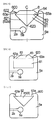
- the decorative part 8 may be shaped (diamond-shaped) to include: the body unit 81 that is tapered downwardly from the maximum diameter portion 82; and the surface exposure portion 83 that is tapered upwardly from the body unit 81. As shown in Fig.
- the decorative part 8 may be shaped to include the body unit 81 that is pillared and the surface exposure portion 83 that is tapered upwardly from the body unit 81 with the maximum diameter portion 82 as the boundary.
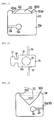
- the decorative part 8 may be pyramidal shaped to include the body unit 81 that is tapered downwardly from the maximum diameter portion 82 whose cross-section has the maximum diameter.
- the decorative part 8 may be spherical or elliptical.
- the decorative part 8 may be shaped to contain the surface exposure portion 83 that is tapered upwardly from the maximum diameter portion 82.
- the positional relation between the decorative part 8 and the snap fastener configuration members is not especially limited.
- the decorative part 8 may be preferably fixed to inside the storage (the first storage 62a) in such a way that the maximum diameter portion 82 of the decorative part 8 is located lower than the surface 600 of the first top stopper 6a. Consequently, the decorative part 8 is stabilized in the storage and unlikely to be fallen off.
- the decorative part 8 may be fixed to inside a storage 32, 42, 62a, 62b, 72a, 72b or 72c in such a way that the top surface of the surface exposure portion 83 of the decorative part 8 is located on the same flat surface as the surface 300, 400, 600 or 700 of at least one of the fastener elements 3a, 3b, the slider 7, the bottom stopper 4 and the top stoppers 6a, 6b or the top surface of the surface exposure portion 83 of the decorative part 8 is located lower than the surface 300, 400, 600 or 700. That is, in the example shown in Fig. 10 , a top surface 83a of the surface exposure portion 83 of the decorative part 8 is located on the same flat surface as the surface 600 of the first top stopper 6a.
- the decorative part 8 When the decorative part 8 is attached, the decorative part 8 is arranged, for example, in the first storage 62a shown in Fig. 3 . After that, from the top surface of the decorative part 8 to the resin layer configuring the first storage 62a, the supersonic vibration of about 20 kHz, preferably, about 20 to 40 kHz is applied to the surface of the decorative part 8 by using a supersonic transmitter. With the application of the supersonic vibration, as shown in Fig.
- the resin located close to the boundary between the first groove 621 and the second groove 622 of the first storage 62a opposite to the maximum diameter portion 82 of the decorative part 8 is melted, and the resin is expansively eluted from a side wall 64 of the second groove 622 inside the first storage 62a, and the fixer 63a (first fixer) for covering a part of the surface exposure portion 83 is formed.
- the fixer 63a is formed such that the resin configuring the first top stopper 6a is partially melted and integrated.
- the decorative part 8 can be fixed easily and efficiently. Since the fixer 63a covers only the part of the surface exposure portion 83, the outer appearance of the decorative part 8 is not damaged, and its design level is also improved.
- Figs. 12 and 13 show the examples when the decorative part 8 is attached to the fastener element 3b.
- the storage 32 is arranged on the surface 300 of the base 35. As shown in Fig. 13 , the storage 32 has a first groove 321 and a second groove 322 which is connected to the first groove 321 above the first groove 321.
- the fastener tape 2b and the core 5b placed at the tip thereof are embedded in the lower portion of the fastener element 3b.
- a length in the lateral direction of the fastener tape 2b embedded in the base 35 is preferred to be 50 % or less of the maximum diameter of the storage 32.
- the tip of the fastener tape 2b (the tip of the core 5b) is preferably arranged so as to be away from the center of the storage 32.
- the body unit 81 is stored in the first groove 321, and the surface exposure portion 83 is stored in the second groove 322.
- the resin configuring the base 35 is melted and protruded from the boundary between the first groove 321 and the second groove 322 (a side wall 34 of the second groove 322), and the fixer (that is not shown) for covering the part of the decorative part 8 is consequently formed.
- Figs. 14 and 15 show the examples when the decorative part 8 is attached to the bottom stopper 4.
- the storage 42 is arranged on the surface 400 of the bottom stopper 4. As shown in Fig. 15 , the storage 42 has a first groove 421 and a second groove 422 which is connected to the first groove 421 above the first groove 421.
- the fastener tapes 2a, 2b and the cores 5a, 5b, which are placed at their tips, respectively, are embedded in the lower portion of the bottom stopper 4. Even in the case shown in Fig. 15 , the tips of the fastener tapes 2a, 2b (the tip of the core 5a) are preferably arranged so as to be away from the center of the storage 42.
- the body unit 81 is stored in the first groove 421, and the surface exposure portion 83 is stored in the second groove 422.
- the resin configuring the bottom stopper 4 is melted and protruded from the boundary between the first groove 421 and the second groove 422 (the vicinity of a side wall 44 of the second groove 422), and the fixer (that is not shown) for covering the part of the decorative part 8 is consequently formed.
- Figs. 16 and 17 show the examples when the decorative part 8 is attached to the puller 75 of the slider 7.
- the storages 72a, 72b and 72c are arranged on the surface 700 of the puller 75.
- the storages 72a, 72b have first grooves 721a, 721b and second grooves 722a, 722b which are connected to the first grooves 721a, 721b above the first grooves 721a, 721b, respectively.
- the decorative part 8 shown in Fig. 5 is arranged in the puller 75, the body unit 81 is stored in the first grooves 721a, 721b, and the surface exposure portion 83 is stored in the second grooves 722a, 722b.
- the resin configuring the bottom stopper 4 is melted and protruded from the boundaries between the first grooves 721a, 721b and the second grooves 722a, 722b, respectively, and the fixer (that is not shown) for covering the part of the decorative part 8 is consequently formed.
- this embodiment indicates the example in which the front surface side of the fastener tapes 2a, 2b is defined as “the upper portion” and the rear surface side of the fastener tapes 2a, 2b is defined as “the lower portion”, and the decorative part 8 is formed on the front surface side of the fastener tapes 2a, 2b in the fastener elements 3a, 3b, the slider 7, the bottom stopper 4 or the top stoppers 6a, 6b.
- the decorative part 8 may be naturally arranged on the rear surface side of the fastener tapes 2a, 2b.
Landscapes
- Engineering & Computer Science (AREA)
- Textile Engineering (AREA)
- Slide Fasteners (AREA)
Abstract
Description
- The present invention relates to a slide fastener, and more particularly relates to a slide fastener in which decorative parts are arranged on configuration members of the slide fastener, and a top stopper for the slide fastener, and a method of producing the slide fastener.
- In a slide fastener, a slider is inserted into left and right element chains that are attached to tape side edges opposite to a pair of left and right fastener tapes, and since the slider is slid along the element chains, the element chains are engaged or separated. In the foregoing slide fastener, decorative parts are arranged on the surfaces of fastener elements and the like, and decoration property is given to improve its esthetic appearance. For example, the publication of Japanese Patent No.
3176936 - However, the invention described in the publication of Japanese Patent No.
3176936 - [Patent Document 1] Japanese Patent No.
3176936 - The present invention provides a slide fastener in which a decorative part and a slide fastener configuration member can be connected stronger and the design level is improved, a top stopper for the slide fastener, and a method of producing the slide fastener.
- In order to solve the above-mentioned problems, the present invention provides, in one aspect, a slide fastener which includes: a pair of fastener tapes; chains of fastener elements arranged along opposing tape side edges of the fastener tapes; a slider for engaging and separating the fastener elements; a bottom stopper arranged at one ends of the chains of the fastener elements on the pair of fastener tapes; and a pair of top stoppers arranged at the other ends of the chains of the fastener elements, wherein the slide fastener includes: a concave storage provided on a surface of at least one of the fastener elements, the slider, the bottom stopper and the top stoppers; a decorative part stored in the storage; and a fixer, which is formed integrally with the storage and protrudes from the storage and fixes the decorative part in the storage.
- In on embodiment of the slide fastener according to the present invention, the decorative part includes a body unit, a surface exposure portion, and a maximum diameter portion whose cross-section has a maximum diameter of the decorative part and defines a boundary between the body unit and the surface exposure portion, wherein the body unit is positioned lower than the maximum diameter portion and the surface exposure portion is tapered upwardly from the body unit, wherein the maximum diameter portion of the decorative part is fixed to inside the storage so as to be arranged lower than the surface of the fastener elements, the slider, the bottom stopper or the top stoppers where the decorative part is arranged.
- In another embodiment of the slide fastener according to the present invention, the decorative part includes a body unit, a surface exposure portion, and a maximum diameter portion whose cross-section has a maximum diameter of the decorative part and defines a boundary between the body unit and the surface exposure portion, wherein the body unit is positioned lower than the maximum diameter portion and the surface exposure portion is tapered upwardly from the body unit, wherein a top surface of the surface exposure portion of the decorative part is fixed to inside the storage so as to be located on the same flat surface as the surface of the fastener elements, the slider, the bottom stopper or the top stoppers or located lower than the surface.
- In still another embodiment of the slide fastener according to the present invention, the decorative part includes a body unit, a surface exposure portion, and a maximum diameter portion whose cross-section has a maximum diameter of the decorative part and defines a boundary between the body unit and the surface exposure portion, wherein the body unit is positioned lower than the maximum diameter portion and the surface exposure portion is tapered upwardly from the body unit, wherein the storage includes a first groove which stores the body unit and a second groove connected to the first groove above the first groove and stores the surface exposure portion, and wherein the fixer is expansively protruded from a side wall of the second groove and covers a part of the surface exposure portion.
- In still another embodiment of the slide fastener according to the present invention, when the decorative part is arranged in one of the fastener elements and the top stoppers, a length in a lateral direction of the fastener tapes embedded in the fastener elements or the top stoppers is 50 % or less of the maximum diameter of the storage.
- In still another embodiment of the slide fastener according to the present invention, when the decorative part is arranged in one of the fastener elements and the top stoppers, the fastener tapes are arranged away from a center of the storage so that the fastener tapes are not embedded on a central axis of the storage.
- The present invention provides, in another aspect, a top stopper for a slide fastener encompassing: a first top stopper made of resin which includes a concave first storage which is arranged on a tape side edge of a first fastener tape and formed on a surface, a first decorative part stored in the first storage, and a first fixer that is integrated with the first storage and protrudes from the first storage and fixes the first decorative part; a second top stopper which includes a concave second storage which is arranged on a tape side edge of a second fastener tape opposite to the first fastener tape and formed on the surface, a second decorative part stored in the second storage, and a second fixer which is integrated with the second storage and protrudes from the second storage and fixes the second decorative part; and a stopper, which is arranged on the tape side edge and located opposite to the fastener element located closest to the side of the first top stopper in the chains of the fastener elements arranged along the tape side edge of the first fastener tape and formed integrally with the second top stopper.
- In an embodiment of the top stoppers for the slide fastener according to the present invention, a center of the first top stopper is arranged so as to be shifted to a side of the second fastener tape from a tip of the first fastener tape embedded in the first top stopper, and a center of the second top stopper is arranged to be shifted to a side of the first fastener tape from a tip of the second fastener tape embedded in the second top stopper.
- The present invention provides, in still another aspect, a method of producing a slide fastener which includes a pair of fastener tapes; chains of fastener elements arranged along opposing tape side edges of the fastener tapes; a slider for engaging and separating the fastener elements; a bottom stopper arranged at one ends of the chains of the fastener elements on the pair of fastener tapes; and a pair of top stoppers arranged at the other ends of the chains of the fastener elements, the method includes: a step of forming a concave storage on a surface of at least one of the fastener elements, the slider, the bottom stopper and the top stoppers; a step of storing a decorative part in the storage; and a step of partially melting a part of the storage and forming a fixer protruding into the storage and fixing the decorative part to inside the storage by using the fixer.
- In an embodiment of the method of producing the slide fastener according to the present invention, the step of partially melting the part of the storage and forming the fixer protruding into the storage includes a step of applying supersonic vibration to the storage and melting a part of the storage.
- According to the present invention, it is possible to provide the slide fastener in which the decorative part and the slide fastener configuration member can be connected more strongly and the design level is improved, and the top stoppers for the slide fastener, and the method of producing the slide fastener.
-
-
Fig. 1 is a schematic view showing an example of a slide fastener according to an embodiment of the present invention; -
Fig. 2 is a side view of the slide fastener inFig. 1 ; -
Fig. 3 is a cross-sectional view showing an example of a top stopper for the slide fastener according to the embodiment of the present invention; -
Fig. 4 is a perspective view showing an example of the top stopper for the slide fastener according to the embodiment of the present invention; -
Fig. 5 is a cross-sectional view showing a situation after a decorative part is fixed to the top stopper for the slide fastener according to the embodiment of the present invention; -
Fig. 6 is a modification of the top stopper shown inFig. 5 ; -
Fig. 7 is another modification of the top stopper shown inFig. 5 ; -
Fig. 8 is still another modification of the top stopper shown inFig. 5 ; -
Fig. 9 is still another modification of the top stopper shown inFig. 5 ; -
Fig. 10 is still another modification of the top stopper shown inFig. 5 ; -
Fig. 11 is still another modification of the top stopper shown inFig. 5 ; -
Fig. 12 is a plan view showing an example of a fastener element of the slide fastener according to the embodiment of the present invention; -
Fig. 13 is a cross-sectional view showing an example of the fastener element inFig. 12 ; -
Fig. 14 is a plan view showing an example of a bottom stopper in the slide fastener according to the embodiment of the present invention; -
Fig. 15 is a cross-sectional view showing an example of the bottom stopper inFig. 14 ; -
Fig. 16 is a plan view showing an example of a puller in a slider according to the embodiment of the present invention+ -
Fig. 17 is a cross-sectional view showing an example viewed from an A-A direction of the puller inFig. 16 . - The embodiment of the present invention will be described below with reference to the drawings. In the following descriptions of the drawings, the same or similar symbol is assigned to the same or similar portion. It is noted that the following embodiment exemplifies an apparatus and method for embodying the technical idea of the present invention and is not intended to limit the structures, arrangements, materials and the like of configuration parts to the followings.
- As shown in
Figs. 1 and2 , aslide fastener 1 according to the embodiment of the present invention includes: a pair offastener tapes fastener elements tape side edges fastener tapes slider 7 for engaging and separating thefastener elements bottom stopper 4 arranged to straddle the pair offastener tapes fastener elements top stoppers fastener elements - In the foregoing and following descriptions, "one ends of the chains of the
fastener elements slide fastener 1 is opened when theslider 7 is slid in the longitudinal direction of thefastener tapes fastener elements slide fastener 1 is closed when theslider 7 is slid in the longitudinal direction of thefastener tapes fastener tapes fastener tapes fastener tapes - For the
fastener tapes cores tape side edges fastener elements fastener tapes fastener tapes Fig. 2 . There is not any limit on the concrete shapes of thefastener elements Fig. 12 , thefastener element 3b includes abase 35 fixed onto thefastener tape 2b, aneck 36 protruding from thebase 35 to the side of theopposite fastener tape 2a, and anengagement head 37 further expanding to the side of thefastener tape 2a from theneck 36. Since theslider 7 shown inFig. 1 is slid from one ends to the other ends of the chains of thefastener elements fastener elements - As shown in
Fig. 2 , theslider 7 includes: aslider body 71 which accommodates thefastener elements fastener elements puller holder 74 arranged on the surface of theslider body 71; and apuller 75 supported by thepuller holder 74. Thebottom stopper 4 is a part that is molded at the vicinity of the bottom ends of the chains of thefastener elements Fig. 1 , and has the outer appearance of an approximate rectangle. On the other hand, thetop stoppers fastener elements Fig. 1 , its planar viewing is circular. Thetop stoppers top stoppers slider 7 located on a directional side in which theslide fastener 1 is closed), respectively, in the front-rear direction of thefastener tapes bottom stopper 4 and thetop stoppers Fig. 1 . The various outer appearances can be naturally employed. - Resins are used for the
fastener elements slider 7, thebottom stopper 4 and thetop stoppers fastener elements slider 7, thebottom stopper 4 and thetop stoppers - The
decorative part 8 is attached onto asurface fastener elements slider 7, thebottom stopper 4 and thetop stoppers decorative parts 8 are attached onto, for example, thetop stoppers Fig. 1 , the firsttop stopper 6a made of the resin is arranged on thetape side edge 21 a of the top end of thefirst fastener tape 2a. The secondtop stopper 6b is arranged on thetape side edge 21b of the top end of thesecond fastener tape 2b opposite to thefirst fastener tape 2a. The firsttop stopper 6a includes: a concavefirst storage 62a formed on thesurface 600; a firstdecorative part 8a stored in thefirst storage 62a; and afirst fixer 63a that is integrated with thefirst storage 62a and protrudes from inside thefirst storage 62a and fixes the firstdecorative part 8a. The secondtop stopper 6b includes: a concavesecond storage 62b formed on thesurface 600; a seconddecorative part 8b stored in thesecond storage 62b; and asecond fixer 63b that is integrated with thesecond storage 62b and protrudes from inside thesecond storage 62b and fixes the seconddecorative part 8b. - As shown in
Figs. 1 and4 , astopper 61, which is arranged on thetape side edge 21b and located opposite to thefastener element 3a (that is not shown) positioned closest to the firsttop stopper 6a in the chains of thefastener elements 3a and formed integrally with the secondtop stopper 6b, is placed on the secondtop stopper 6b. A thickness of the front-rear direction of thefastener tape 2b of thestopper 61 is equal to each of thefastener elements fastener tape 2b of thestopper 61 is approximately equal to a length of thebase 35 of thefastener element 3b. Since thestopper 61 is formed, theslider 7 can be protected from being separated from the chains of thefastener elements fastener tapes - As shown in
Fig. 3 , thefirst storage 62a includes: afirst groove 621 whose shape is tapered as it goes toward a lower portion (the depth direction) of thetop stopper 6a; and asecond groove 622 that is connected to thefirst groove 621 above thefirst groove 621 and linked to thesurface 600. As shown inFig. 5 , when with amaximum diameter portion 82 whose cross-section has the maximum diameter as a boundary, thedecorative part 8 includes abody unit 81 positioned lower than themaximum diameter portion 82, and asurface exposure portion 83 that is tapered upwardly from thebody unit 81, thebody unit 81 of thedecorative parts 8 is stored in thefirst groove 621, and thesurface exposure portion 83 is stored in thesecond groove 622. As shown inFig. 3 , thefastener tape 2a which has thecore 5a at its tip is embedded in a further lower portion of thefirst storage 62a. In the present embodiment, a tip of thefastener tape 2a (core 5a) is preferably located just under a center 623 (central axis C) of thefirst storage 62a, or arranged so as to be shifted from the center 623 (central axis C). In other words, the center 623 (central axis C) of the firsttop stopper 6a is preferably located just under the tip of thefirst fastener tape 2a embedded in the firsttop stopper 6a, or arranged so as to be shifted to the side of thesecond fastener tape 2b from the tip. Similarly, the center (that is not shown) of the secondtop stopper 6b shown inFig. 1 or4 is preferably located at the tip of thesecond fastener tape 2b embedded in the secondtop stopper 6b, or arranged so as to be shifted to the side of thefirst fastener tape 2a from the tip. Since thefastener tape 2a and thecore 5a are arranged so as to be shifted from the central axis C, in a producing method that will be described later, the vibration generated when thedecorative part 8 is fixed is unlikely to be transmitted to thefastener tape 2a orcore 5a. Thus, a work for fixing thedecorative part 8 can be completed in a short time. Although values are not limited to the followings, in order to efficiently fix thedecorative part 8, a displacement d4 (refer toFig. 3 ) in a width direction (lateral direction) between the tip of thefastener tape 2a (the tip of the core 5a) and the central axis C can be separated by a distance of, for example, 0 mm or more, preferably, about 0 to 1 mm. - A length d2 in the lateral direction of the
fastener tape 2a embedded in the firsttop stopper 6a is preferred to be 50 % or less of a length in a width direction of a maximum diameter d1 of thefirst storage 62a and further preferred to be 25 to 50 %. With the employment of such configuration, when thedecorative part 8 is welled and fixed by supersonic vibration, the supersonic vibration is more efficiently transmitted to the resin layer configuring the firsttop stopper 6a, as compared with thefastener tape 2a and thecore 5a. Thus, thedecorative part 8 can be fixed more efficiently in a shorter time. Although values are not limited to the followings, a distance d3 between the center (the deepest portion) 623 of thefirst storage 62a and the highest end of thefastener tape 2a (core 5a) can be typically set to about 0 to 1 mm. Although their illustrations and detailed explanations are omitted, even for thesecond storage 62b of the secondtop stopper 6b, it is naturally possible to employ the configuration substantially equal to the firsttop stopper 6a. - In a case of a member whose object lies in jewelry such as a crystal, a stone, a jewel and the like, the material of the
decorative part 8 is not especially limited. Also, there is not any limit on the concrete shapes of thedecorative part 8. For example, as shown inFig. 5 or10 , with themaximum diameter portion 82 whose cross-section has the maximum diameter as the boundary, thedecorative part 8 may be shaped (diamond-shaped) to include: thebody unit 81 that is tapered downwardly from themaximum diameter portion 82; and thesurface exposure portion 83 that is tapered upwardly from thebody unit 81. As shown inFig. 6 , thedecorative part 8 may be shaped to include thebody unit 81 that is pillared and thesurface exposure portion 83 that is tapered upwardly from thebody unit 81 with themaximum diameter portion 82 as the boundary. As shown inFig. 7 or8 , thedecorative part 8 may be pyramidal shaped to include thebody unit 81 that is tapered downwardly from themaximum diameter portion 82 whose cross-section has the maximum diameter. As shown inFig. 9 , thedecorative part 8 may be spherical or elliptical. As shown inFig. 11 , thedecorative part 8 may be shaped to contain thesurface exposure portion 83 that is tapered upwardly from themaximum diameter portion 82. - The positional relation between the
decorative part 8 and the snap fastener configuration members (thefastener elements slider 7, thebottom stopper 4 and thetop stoppers decorative part 8 may be preferably fixed to inside the storage (thefirst storage 62a) in such a way that themaximum diameter portion 82 of thedecorative part 8 is located lower than thesurface 600 of the firsttop stopper 6a. Consequently, thedecorative part 8 is stabilized in the storage and unlikely to be fallen off. - Also, the
decorative part 8 may be fixed to inside astorage surface exposure portion 83 of thedecorative part 8 is located on the same flat surface as thesurface fastener elements slider 7, thebottom stopper 4 and thetop stoppers surface exposure portion 83 of thedecorative part 8 is located lower than thesurface Fig. 10 , a top surface 83a of thesurface exposure portion 83 of thedecorative part 8 is located on the same flat surface as thesurface 600 of the firsttop stopper 6a. Consequently, as compared with a case in which thesurface exposure portion 83 protrudes from thesurface 600 of the firsttop stopper 6a, the influence of the friction caused by outer contact and the like is unlikely to be received, which causes thedecorative part 8 to be unlikely to be fallen off from theslide fastener 1. - When the
decorative part 8 is attached, thedecorative part 8 is arranged, for example, in thefirst storage 62a shown inFig. 3 . After that, from the top surface of thedecorative part 8 to the resin layer configuring thefirst storage 62a, the supersonic vibration of about 20 kHz, preferably, about 20 to 40 kHz is applied to the surface of thedecorative part 8 by using a supersonic transmitter. With the application of the supersonic vibration, as shown inFig. 5 , the resin located close to the boundary between thefirst groove 621 and thesecond groove 622 of thefirst storage 62a opposite to themaximum diameter portion 82 of thedecorative part 8 is melted, and the resin is expansively eluted from aside wall 64 of thesecond groove 622 inside thefirst storage 62a, and thefixer 63a (first fixer) for covering a part of thesurface exposure portion 83 is formed. Thefixer 63a is formed such that the resin configuring the firsttop stopper 6a is partially melted and integrated. Thus, as compared with a case in which it is fixed onto thesurface exposure portion 83 by using a different member, thedecorative part 8 is unlikely to be separated, which enables thedecorative part 8 and the slide fastener configuration member to be more strongly connected. Moreover, since the resin is melted and eluted by the supersonic vibration, thedecorative part 8 can be fixed easily and efficiently. Since thefixer 63a covers only the part of thesurface exposure portion 83, the outer appearance of thedecorative part 8 is not damaged, and its design level is also improved. -
Figs. 12 and 13 show the examples when thedecorative part 8 is attached to thefastener element 3b. Thestorage 32 is arranged on thesurface 300 of thebase 35. As shown inFig. 13 , thestorage 32 has afirst groove 321 and asecond groove 322 which is connected to thefirst groove 321 above thefirst groove 321. Thefastener tape 2b and thecore 5b placed at the tip thereof are embedded in the lower portion of thefastener element 3b. A length in the lateral direction of thefastener tape 2b embedded in thebase 35 is preferred to be 50 % or less of the maximum diameter of thestorage 32. Also, the tip of thefastener tape 2b (the tip of the core 5b) is preferably arranged so as to be away from the center of thestorage 32. When thedecorative part 8 shown inFig. 5 is arranged in thestorage 32, thebody unit 81 is stored in thefirst groove 321, and thesurface exposure portion 83 is stored in thesecond groove 322. After that, since the supersonic vibration is applied to thedecorative part 8, the resin configuring thebase 35 is melted and protruded from the boundary between thefirst groove 321 and the second groove 322 (aside wall 34 of the second groove 322), and the fixer (that is not shown) for covering the part of thedecorative part 8 is consequently formed. -
Figs. 14 and 15 show the examples when thedecorative part 8 is attached to thebottom stopper 4. Thestorage 42 is arranged on thesurface 400 of thebottom stopper 4. As shown inFig. 15 , thestorage 42 has afirst groove 421 and asecond groove 422 which is connected to thefirst groove 421 above thefirst groove 421. Thefastener tapes cores bottom stopper 4. Even in the case shown inFig. 15 , the tips of thefastener tapes storage 42. When thedecorative part 8 shown inFig. 5 is arranged in thestorage 42, thebody unit 81 is stored in thefirst groove 421, and thesurface exposure portion 83 is stored in thesecond groove 422. After that, since the supersonic vibration is applied to thedecorative part 8 and thebottom stopper 4, the resin configuring thebottom stopper 4 is melted and protruded from the boundary between thefirst groove 421 and the second groove 422 (the vicinity of aside wall 44 of the second groove 422), and the fixer (that is not shown) for covering the part of thedecorative part 8 is consequently formed. -
Figs. 16 and17 show the examples when thedecorative part 8 is attached to thepuller 75 of theslider 7. Thestorages surface 700 of thepuller 75. As shown inFig. 17 , thestorages first grooves second grooves first grooves first grooves decorative part 8 shown inFig. 5 is arranged in thepuller 75, thebody unit 81 is stored in thefirst grooves surface exposure portion 83 is stored in thesecond grooves decorative part 8 and thepuller 75, the resin configuring thebottom stopper 4 is melted and protruded from the boundaries between thefirst grooves second grooves decorative part 8 is consequently formed. - Although the embodiments of the present invention have been described as mentioned above, the discussions and drawings that configure a part of this disclosure should not be understood to limit the present invention. For example, this embodiment indicates the example in which the front surface side of the
fastener tapes fastener tapes decorative part 8 is formed on the front surface side of thefastener tapes fastener elements slider 7, thebottom stopper 4 or thetop stoppers decorative part 8 may be naturally arranged on the rear surface side of thefastener tapes fastener tapes fastener tapes -
- 1
- Slide Fastener
- 2a, 2b
- Fastener Tape
- 3a, 3b
- Fastener Element
- 4
- Bottom Stopper
- 5a, 5b
- Core
- 6a, 6b
- Top Stopper
- 7
- Slider
- 8, 8a, 8b
- Decorative part
- 21a, 21b
- Tape Side Edge
- 32, 42, 62a, 62b, 72a, 72b, 72c
- Storage
- 33, 63a, 63b
- Fixer
- 34, 44, 64
- Side Wall
- 61
- Stopper
- 71
- Slider Body
- 74
- Puller Holder
- 75
- Puller
- 81
- Body Unit
- 82
- Maximum Diameter Portion
- 83
- Surface Exposure Portion
- 83a
- Top Surface
- 300, 400, 600, 700
- Surface
- 321, 421, 621, 721a, 721b
- First Groove
- 322, 422, 622, 722a, 722b
- Second Groove
Claims (10)
- A slide fastener (1) comprising:a pair of fastener tapes (2a, 2b);chains of fastener elements (3a, 3b) arranged along opposing tape side edges (21a, 21b) of the fastener tapes (2a, 2b);a slider (7) for engaging and separating the fastener elements (3a, 3b);a bottom stopper (4) arranged at one ends of the chains of the fastener elements (3a, 3b) on the pair of fastener tapes (2a, 2b); anda pair of top stoppers (6a, 6b) arranged at the other ends of the chains of the fastener elements (3a, 3b),wherein the slide fastener (1) comprises:a concave storage (32, 42, 62a, 62b, 72a, 72b, 72c) provided on a surface (300, 400, 600, 700) of at least one of the fastener elements (3a, 3b), the slider (7), the bottom stopper (4) and the top stoppers (6a, 6b);a decorative part (8, 8a, 8b) stored in the storage (32, 42, 62a, 62b, 72a, 72b, 72c); anda fixer (33, 63a, 63b), which is formed integrally with the storage (32, 42, 62a, 62b, 72a, 72b, 72c) and protrudes from the storage (32, 42, 62a, 62b, 72a, 72b, 72c) and fixes the decorative part (8, 8a, 8b) in the storage (32, 42, 62a, 62b, 72a, 72b, 72c).
- The slide fastener (1) according to the claim 1, wherein the decorative part (8, 8a, 8b) comprises a body unit (81), a surface exposure portion (83), and a maximum diameter portion (82) whose cross-section has a maximum diameter of the decorative part (8, 8a, 8b) and defines a boundary between the body unit (81) and the surface exposure portion (83), wherein the body unit (81) is positioned lower than the maximum diameter portion (82) and the surface exposure portion (83) is tapered upwardly from the body unit (81),
wherein the maximum diameter portion (82) of the decorative part (8, 8a, 8b) is fixed to inside the storage (32, 42, 62a, 62b, 72a, 72b, 72c) so as to be arranged lower than the surface (300, 400, 600, 700) of the fastener elements (3a, 3b), the slider (7), the bottom stopper (4) or the top stoppers (6a, 6b) where the decorative part (8, 8a, 8b) is arranged. - The slide fastener (1) according to the claim 1, wherein the decorative part (8, 8a, 8b) comprises a body unit (81), a surface exposure portion (83), and a maximum diameter portion (82) whose cross-section has a maximum diameter of the decorative part (8, 8a, 8b) and defines a boundary between the body unit (81) and the surface exposure portion (83), wherein the body unit (81) is positioned lower than the maximum diameter portion (82) and the surface exposure portion (83) is tapered upwardly from the body unit (81),
wherein a top surface (83a) of the surface exposure portion (83) of the decorative part (8, 8a, 8b) is fixed to inside the storage (32, 42, 62a, 62b, 72a, 72b, 72c) so as to be located on the same flat surface as the surface (300, 400, 600, 700) of the fastener elements (3a, 3b), the slider (7), the bottom stopper (4) or the top stoppers (6a, 6b) or located lower than the surface (300, 400, 600, 700). - The slide fastener (1) according to the claim 1, wherein the decorative part (8, 8a, 8b) comprises a body unit (81), a surface exposure portion (83), and a maximum diameter portion (82) whose cross-section has a maximum diameter of the decorative part (8, 8a, 8b) and defines a boundary between the body unit (81) and the surface exposure portion (83), wherein the body unit (81) is positioned lower than the maximum diameter portion (82) and the surface exposure portion (83) is tapered upwardly from the body unit (81),
wherein the storage (32, 42, 62a, 62b, 72a, 72b, 72c) comprises a first groove (321, 421, 621, 721a, 721b) which stores the body unit (81) and a second groove (322, 422, 622, 722a, 722b) connected to the first groove (321, 421, 621, 721a, 721b) above the first groove (321, 421, 621, 721a, 721b) and stores the surface exposure portion (83),
and wherein the fixer (33, 63a, 63b) is expansively protruded from a side wall (34, 64) of the second groove (322, 422, 622, 722a, 722b) and covers a part of the surface exposure portion (83). - The slide fastener (1) according to the claim 1, wherein, when the decorative part (8, 8a, 8b) is arranged in one of the fastener elements (3a, 3b) and the top stoppers (6a, 6b), a length in a lateral direction of the fastener tapes (2a, 2b) embedded in the fastener elements (3a, 3b) or the top stoppers (6a, 6b) is 50 % or less of the maximum diameter of the storage (32, 42, 62a, 62b).
- The slide fastener (1) according to the claim 1, wherein, when the decorative part (8, 8a 8b) is arranged in one of the fastener elements (3a, 3b) and the top stoppers (6a, 6b), the fastener tapes (2a, 2b) are arranged away from a center of the storage (32, 62a, 62b) so that the fastener tapes (2a, 2b) are not embedded on a central axis of the storage (32, 62a, 62b).
- A top stopper (6a, 6b) for a slide fastener (1) comprising:a first top stopper (6a) made of resin which comprises a concave first storage (62a) which is arranged on a tape side edge (21a) of a first fastener tape (2a) and formed on a surface (600), a first decorative part (8a) stored in the first storage (62a), and a first fixer (63a) that is integrated with the first storage (62a) and protrudes from the first storage (62a) and fixes the first decorative part (8a);a second top stopper (6b) which comprises a concave second storage (62b) which is arranged on a tape side edge (21b) of a second fastener tape (2b) opposite to the first fastener tape (2a) and formed on the surface (600), a second decorative part (8b) stored in the second storage (62b), and a second fixer (63b) which is integrated with the second storage (62b) and protrudes from the second storage (62b) and fixes the second decorative part (8b); anda stopper (61), which is arranged on the tape side edge (21b) and located opposite to the fastener element (3a) located closest to the side of the first top stopper (6a) in the chains of the fastener elements (3a) arranged along the tape side edge (21a) of the first fastener tape (2a) and formed integrally with the second top stopper (6b).
- The top stopper (6a, 6b) for the slide fastener, according to the claim 7, wherein a center of the first top stopper (6a) is arranged so as to be shifted to a side of the second fastener tape (2b) from a tip of the first fastener tape (2a) embedded in the first top stopper (6a), and a center of the second top stopper (6b) is arranged to be shifted to a side of the first fastener tape (2a) from a tip of the second fastener tape (2b) embedded in the second top stopper (6b).
- A method of producing a slide fastener (1) which comprises a pair of fastener tapes (2a, 2b); chains of fastener elements (3a, 3b) arranged along opposing tape side edges (21a, 21b) of the fastener tapes (2a, 2b); a slider (7) for engaging and separating the fastener elements (3a, 3b); a bottom stopper (4) arranged at one ends of the chains of the fastener elements (3a, 3b) on the pair of fastener tapes (2a, 2b); and a pair of top stoppers (6a, 6b) arranged at the other ends of the chains of the fastener elements (3a, 3b), the method comprises:a step of forming a concave storage (32, 42, 62a, 62b, 72a, 72b, 72c) on a surface (300, 400, 600, 700) of at least one of the fastener elements (3a, 3b), the slider (7), the bottom stopper (4) and the top stoppers (6a, 6b);a step of storing a decorative part (8, 8a, 8b) in the storage (32, 42, 62a, 62b, 72a, 72b, 72c); anda step of partially melting a part of the storage (32, 42, 62a, 62b, 72a, 72b, 72c) and forming a fixer (33, 63a, 63b) protruding into the storage (32, 42, 62a, 62b, 72a, 72b, 72c) and fixing the decorative part (8, 8a, 8b) to inside the storage (32, 42, 62a, 62b, 72a, 72b, 72c) by using the fixer (33, 63a, 63b).
- The method of producing the slide fastener (1) according to the claim 9, wherein the step of partially melting the part of the storage (32, 42, 62a, 62b, 72a, 72b, 72c) and forming the fixer (33, 63a, 63b) protruding into the storage (32, 42, 62a, 62b, 72a, 72b, 72c) includes a step of applying supersonic vibration to the storage (32, 42, 62a, 62b, 72a, 72b, 72c) and melting a part of the storage (32, 42, 62a, 62b, 72a, 72b, 72c).
Applications Claiming Priority (1)
| Application Number | Priority Date | Filing Date | Title |
|---|---|---|---|
| PCT/JP2010/067893 WO2012049736A1 (en) | 2010-10-12 | 2010-10-12 | Slide fastener, top stop for slide fasteners and slide fastener production method |
Publications (3)
| Publication Number | Publication Date |
|---|---|
| EP2628404A1 true EP2628404A1 (en) | 2013-08-21 |
| EP2628404A4 EP2628404A4 (en) | 2015-05-27 |
| EP2628404B1 EP2628404B1 (en) | 2017-07-26 |
Family
ID=45937986
Family Applications (1)
| Application Number | Title | Priority Date | Filing Date |
|---|---|---|---|
| EP10858391.5A Active EP2628404B1 (en) | 2010-10-12 | 2010-10-12 | Slide fastener, top stop for slide fasteners and slide fastener production method |
Country Status (5)
| Country | Link |
|---|---|
| EP (1) | EP2628404B1 (en) |
| JP (1) | JPWO2012049736A1 (en) |
| CN (1) | CN103260454B (en) |
| TW (1) | TWI504360B (en) |
| WO (1) | WO2012049736A1 (en) |
Cited By (3)
| Publication number | Priority date | Publication date | Assignee | Title |
|---|---|---|---|---|
| CN103211358A (en) * | 2013-01-21 | 2013-07-24 | 开易(广东)服装配件有限公司 | Upper stop component for fast release zipper |
| CN107087861A (en) * | 2017-06-27 | 2017-08-25 | 陈恩光 | A kind of radium-shine brill slide fastener and its manufacture method |
| CN109770484A (en) * | 2017-11-15 | 2019-05-21 | Ykk株式会社 | Stopper for zipper and manufacturing method of zipper |
Families Citing this family (3)
| Publication number | Priority date | Publication date | Assignee | Title |
|---|---|---|---|---|
| TWI566923B (en) * | 2012-05-02 | 2017-01-21 | Automatic zipper manufacturing method and its automation machine | |
| CN104231589A (en) * | 2014-10-11 | 2014-12-24 | 江苏宏达拉链制造有限公司 | High-intensity resin zipper |
| CN109054339A (en) * | 2018-09-21 | 2018-12-21 | 浙江伟星实业发展股份有限公司 | A kind of resin chain tooth, resin teeth zipper and preparation method thereof |
Family Cites Families (14)
| Publication number | Priority date | Publication date | Assignee | Title |
|---|---|---|---|---|
| US2495033A (en) * | 1946-05-04 | 1950-01-17 | North & Judd Mfg Co | Slider fastener |
| US3825978A (en) * | 1972-03-13 | 1974-07-30 | Brier Mfg Co | Zipper construction |
| JPS5535192Y2 (en) * | 1977-03-28 | 1980-08-19 | ||
| JPS6239706Y2 (en) * | 1981-05-15 | 1987-10-09 | ||
| JPS6151023U (en) * | 1984-09-10 | 1986-04-05 | ||
| JPH0675523B2 (en) * | 1988-12-16 | 1994-09-28 | 吉田工業株式会社 | Manufacturing method for jewelry |
| US5511292A (en) * | 1995-06-28 | 1996-04-30 | D. Swarovski & Co. | Zipper closure |
| TW311372U (en) * | 1996-06-12 | 1997-07-21 | Lan-Fang Ye | Plastic object structure combined with diamond decoration |
| DE29611270U1 (en) * | 1996-06-27 | 1996-09-05 | D. Swarovski & Co., Wattens | Zipper |
| US5713110A (en) * | 1996-10-01 | 1998-02-03 | D. Swarovski & Co. | Zipper closure with decorative stones |
| JP3708046B2 (en) * | 2001-12-13 | 2005-10-19 | Ykk株式会社 | Slide fastener |
| CN2610833Y (en) * | 2003-03-28 | 2004-04-14 | 魏华平 | Decoration insertion for gift |
| JP4447599B2 (en) * | 2006-12-28 | 2010-04-07 | Ykk株式会社 | Top stopper for slide fastener |
| CN200990922Y (en) * | 2006-12-31 | 2007-12-19 | 福建浔兴拉链科技股份有限公司 | Zipper upper-stopper |
-
2010
- 2010-10-12 CN CN201080070633.XA patent/CN103260454B/en active Active
- 2010-10-12 JP JP2012538495A patent/JPWO2012049736A1/en active Pending
- 2010-10-12 WO PCT/JP2010/067893 patent/WO2012049736A1/en not_active Ceased
- 2010-10-12 EP EP10858391.5A patent/EP2628404B1/en active Active
-
2011
- 2011-03-09 TW TW100107968A patent/TWI504360B/en active
Non-Patent Citations (1)
| Title |
|---|
| See references of WO2012049736A1 * |
Cited By (6)
| Publication number | Priority date | Publication date | Assignee | Title |
|---|---|---|---|---|
| CN103211358A (en) * | 2013-01-21 | 2013-07-24 | 开易(广东)服装配件有限公司 | Upper stop component for fast release zipper |
| CN103211358B (en) * | 2013-01-21 | 2015-08-19 | 开易(广东)服装配件有限公司 | A kind of upper only assembly of fast de-slide fastener |
| CN107087861A (en) * | 2017-06-27 | 2017-08-25 | 陈恩光 | A kind of radium-shine brill slide fastener and its manufacture method |
| CN107087861B (en) * | 2017-06-27 | 2019-10-18 | 陈恩光 | The radium-shine brill zipper of one kind and its manufacturing method |
| CN109770484A (en) * | 2017-11-15 | 2019-05-21 | Ykk株式会社 | Stopper for zipper and manufacturing method of zipper |
| CN109770484B (en) * | 2017-11-15 | 2021-07-20 | Ykk株式会社 | Stopper for zipper and manufacturing method of zipper |
Also Published As
| Publication number | Publication date |
|---|---|
| JPWO2012049736A1 (en) | 2014-02-24 |
| TW201215343A (en) | 2012-04-16 |
| WO2012049736A1 (en) | 2012-04-19 |
| EP2628404A4 (en) | 2015-05-27 |
| CN103260454B (en) | 2016-01-20 |
| TWI504360B (en) | 2015-10-21 |
| EP2628404B1 (en) | 2017-07-26 |
| CN103260454A (en) | 2013-08-21 |
Similar Documents
| Publication | Publication Date | Title |
|---|---|---|
| EP2628404B1 (en) | Slide fastener, top stop for slide fasteners and slide fastener production method | |
| US10757993B2 (en) | Cap with exchangeable visor | |
| EP1640147B1 (en) | Polygonal rib structure, mold and molding method therefore | |
| US9307809B2 (en) | Slide fastener | |
| EP1723868A2 (en) | Slide fastener chain | |
| EP1938706A1 (en) | Slide fastener top end stop | |
| EP3200646B1 (en) | Applicator for applying a cosmetic product | |
| US8464472B2 (en) | Weather strip | |
| CN207561458U (en) | Slider for slide fastener | |
| JP2008281169A (en) | Retainer | |
| CN106880133B (en) | Slider for slide fastener | |
| KR102044721B1 (en) | Cuticle-Material Retaining Clip | |
| CN106901456B (en) | Zipper stringer, its manufacturing method, and mold | |
| US10625944B2 (en) | Profiled belt and method for manufacturing same | |
| JP5345365B2 (en) | Method for manufacturing attachment member and method for using manufactured attachment member | |
| US7654422B2 (en) | Needle threader | |
| US9611574B2 (en) | Sewing tool holder | |
| EP3139713B1 (en) | Electronic device and assembly method thereof | |
| US6439537B1 (en) | Forming mold with recess having snap-fit end seal | |
| JPH018185Y2 (en) | ||
| CN103228168B (en) | The manufacture method of the stop of slide fastener and slide fastener | |
| JPWO2012043047A1 (en) | Slide fastener and method for manufacturing slide fastener stop | |
| JP2000272472A (en) | Seat belt insertion tool | |
| JP2006181830A (en) | Gate processing molded products | |
| JPH03292129A (en) | Molded product for fitting |
Legal Events
| Date | Code | Title | Description |
|---|---|---|---|
| PUAI | Public reference made under article 153(3) epc to a published international application that has entered the european phase |
Free format text: ORIGINAL CODE: 0009012 |
|
| 17P | Request for examination filed |
Effective date: 20130425 |
|
| AK | Designated contracting states |
Kind code of ref document: A1 Designated state(s): AL AT BE BG CH CY CZ DE DK EE ES FI FR GB GR HR HU IE IS IT LI LT LU LV MC MK MT NL NO PL PT RO RS SE SI SK SM TR |
|
| DAX | Request for extension of the european patent (deleted) | ||
| RA4 | Supplementary search report drawn up and despatched (corrected) |
Effective date: 20150429 |
|
| RIC1 | Information provided on ipc code assigned before grant |
Ipc: A44B 19/42 20060101ALI20150422BHEP Ipc: A44B 19/36 20060101AFI20150422BHEP Ipc: A44B 19/38 20060101ALI20150422BHEP Ipc: A41D 27/08 20060101ALI20150422BHEP Ipc: A44B 19/14 20060101ALI20150422BHEP Ipc: A44B 19/26 20060101ALI20150422BHEP Ipc: A44B 19/24 20060101ALI20150422BHEP Ipc: A44B 19/02 20060101ALI20150422BHEP |
|
| 17Q | First examination report despatched |
Effective date: 20160323 |
|
| GRAP | Despatch of communication of intention to grant a patent |
Free format text: ORIGINAL CODE: EPIDOSNIGR1 |
|
| INTG | Intention to grant announced |
Effective date: 20170323 |
|
| GRAS | Grant fee paid |
Free format text: ORIGINAL CODE: EPIDOSNIGR3 |
|
| GRAA | (expected) grant |
Free format text: ORIGINAL CODE: 0009210 |
|
| AK | Designated contracting states |
Kind code of ref document: B1 Designated state(s): AL AT BE BG CH CY CZ DE DK EE ES FI FR GB GR HR HU IE IS IT LI LT LU LV MC MK MT NL NO PL PT RO RS SE SI SK SM TR |
|
| REG | Reference to a national code |
Ref country code: GB Ref legal event code: FG4D |
|
| REG | Reference to a national code |
Ref country code: CH Ref legal event code: EP |
|
| REG | Reference to a national code |
Ref country code: AT Ref legal event code: REF Ref document number: 911669 Country of ref document: AT Kind code of ref document: T Effective date: 20170815 |
|
| REG | Reference to a national code |
Ref country code: IE Ref legal event code: FG4D |
|
| REG | Reference to a national code |
Ref country code: DE Ref legal event code: R096 Ref document number: 602010043979 Country of ref document: DE |
|
| REG | Reference to a national code |
Ref country code: FR Ref legal event code: PLFP Year of fee payment: 8 |
|
| REG | Reference to a national code |
Ref country code: NL Ref legal event code: MP Effective date: 20170726 |
|
| REG | Reference to a national code |
Ref country code: LT Ref legal event code: MG4D |
|
| REG | Reference to a national code |
Ref country code: AT Ref legal event code: MK05 Ref document number: 911669 Country of ref document: AT Kind code of ref document: T Effective date: 20170726 |
|
| PG25 | Lapsed in a contracting state [announced via postgrant information from national office to epo] |
Ref country code: FI Free format text: LAPSE BECAUSE OF FAILURE TO SUBMIT A TRANSLATION OF THE DESCRIPTION OR TO PAY THE FEE WITHIN THE PRESCRIBED TIME-LIMIT Effective date: 20170726 Ref country code: SE Free format text: LAPSE BECAUSE OF FAILURE TO SUBMIT A TRANSLATION OF THE DESCRIPTION OR TO PAY THE FEE WITHIN THE PRESCRIBED TIME-LIMIT Effective date: 20170726 Ref country code: LT Free format text: LAPSE BECAUSE OF FAILURE TO SUBMIT A TRANSLATION OF THE DESCRIPTION OR TO PAY THE FEE WITHIN THE PRESCRIBED TIME-LIMIT Effective date: 20170726 Ref country code: NL Free format text: LAPSE BECAUSE OF FAILURE TO SUBMIT A TRANSLATION OF THE DESCRIPTION OR TO PAY THE FEE WITHIN THE PRESCRIBED TIME-LIMIT Effective date: 20170726 Ref country code: NO Free format text: LAPSE BECAUSE OF FAILURE TO SUBMIT A TRANSLATION OF THE DESCRIPTION OR TO PAY THE FEE WITHIN THE PRESCRIBED TIME-LIMIT Effective date: 20171026 Ref country code: HR Free format text: LAPSE BECAUSE OF FAILURE TO SUBMIT A TRANSLATION OF THE DESCRIPTION OR TO PAY THE FEE WITHIN THE PRESCRIBED TIME-LIMIT Effective date: 20170726 Ref country code: AT Free format text: LAPSE BECAUSE OF FAILURE TO SUBMIT A TRANSLATION OF THE DESCRIPTION OR TO PAY THE FEE WITHIN THE PRESCRIBED TIME-LIMIT Effective date: 20170726 |
|
| PG25 | Lapsed in a contracting state [announced via postgrant information from national office to epo] |
Ref country code: LV Free format text: LAPSE BECAUSE OF FAILURE TO SUBMIT A TRANSLATION OF THE DESCRIPTION OR TO PAY THE FEE WITHIN THE PRESCRIBED TIME-LIMIT Effective date: 20170726 Ref country code: PL Free format text: LAPSE BECAUSE OF FAILURE TO SUBMIT A TRANSLATION OF THE DESCRIPTION OR TO PAY THE FEE WITHIN THE PRESCRIBED TIME-LIMIT Effective date: 20170726 Ref country code: GR Free format text: LAPSE BECAUSE OF FAILURE TO SUBMIT A TRANSLATION OF THE DESCRIPTION OR TO PAY THE FEE WITHIN THE PRESCRIBED TIME-LIMIT Effective date: 20171027 Ref country code: RS Free format text: LAPSE BECAUSE OF FAILURE TO SUBMIT A TRANSLATION OF THE DESCRIPTION OR TO PAY THE FEE WITHIN THE PRESCRIBED TIME-LIMIT Effective date: 20170726 Ref country code: IS Free format text: LAPSE BECAUSE OF FAILURE TO SUBMIT A TRANSLATION OF THE DESCRIPTION OR TO PAY THE FEE WITHIN THE PRESCRIBED TIME-LIMIT Effective date: 20171126 Ref country code: BG Free format text: LAPSE BECAUSE OF FAILURE TO SUBMIT A TRANSLATION OF THE DESCRIPTION OR TO PAY THE FEE WITHIN THE PRESCRIBED TIME-LIMIT Effective date: 20171026 Ref country code: ES Free format text: LAPSE BECAUSE OF FAILURE TO SUBMIT A TRANSLATION OF THE DESCRIPTION OR TO PAY THE FEE WITHIN THE PRESCRIBED TIME-LIMIT Effective date: 20170726 |
|
| PG25 | Lapsed in a contracting state [announced via postgrant information from national office to epo] |
Ref country code: CZ Free format text: LAPSE BECAUSE OF FAILURE TO SUBMIT A TRANSLATION OF THE DESCRIPTION OR TO PAY THE FEE WITHIN THE PRESCRIBED TIME-LIMIT Effective date: 20170726 Ref country code: RO Free format text: LAPSE BECAUSE OF FAILURE TO SUBMIT A TRANSLATION OF THE DESCRIPTION OR TO PAY THE FEE WITHIN THE PRESCRIBED TIME-LIMIT Effective date: 20170726 Ref country code: DK Free format text: LAPSE BECAUSE OF FAILURE TO SUBMIT A TRANSLATION OF THE DESCRIPTION OR TO PAY THE FEE WITHIN THE PRESCRIBED TIME-LIMIT Effective date: 20170726 |
|
| REG | Reference to a national code |
Ref country code: DE Ref legal event code: R097 Ref document number: 602010043979 Country of ref document: DE |
|
| REG | Reference to a national code |
Ref country code: DE Ref legal event code: R119 Ref document number: 602010043979 Country of ref document: DE |
|
| PG25 | Lapsed in a contracting state [announced via postgrant information from national office to epo] |
Ref country code: EE Free format text: LAPSE BECAUSE OF FAILURE TO SUBMIT A TRANSLATION OF THE DESCRIPTION OR TO PAY THE FEE WITHIN THE PRESCRIBED TIME-LIMIT Effective date: 20170726 Ref country code: SK Free format text: LAPSE BECAUSE OF FAILURE TO SUBMIT A TRANSLATION OF THE DESCRIPTION OR TO PAY THE FEE WITHIN THE PRESCRIBED TIME-LIMIT Effective date: 20170726 Ref country code: SM Free format text: LAPSE BECAUSE OF FAILURE TO SUBMIT A TRANSLATION OF THE DESCRIPTION OR TO PAY THE FEE WITHIN THE PRESCRIBED TIME-LIMIT Effective date: 20170726 Ref country code: MC Free format text: LAPSE BECAUSE OF FAILURE TO SUBMIT A TRANSLATION OF THE DESCRIPTION OR TO PAY THE FEE WITHIN THE PRESCRIBED TIME-LIMIT Effective date: 20170726 |
|
| REG | Reference to a national code |
Ref country code: CH Ref legal event code: PL |
|
| PLBE | No opposition filed within time limit |
Free format text: ORIGINAL CODE: 0009261 |
|
| STAA | Information on the status of an ep patent application or granted ep patent |
Free format text: STATUS: NO OPPOSITION FILED WITHIN TIME LIMIT |
|
| GBPC | Gb: european patent ceased through non-payment of renewal fee |
Effective date: 20171026 |
|
| 26N | No opposition filed |
Effective date: 20180430 |
|
| REG | Reference to a national code |
Ref country code: IE Ref legal event code: MM4A |
|
| PG25 | Lapsed in a contracting state [announced via postgrant information from national office to epo] |
Ref country code: DE Free format text: LAPSE BECAUSE OF NON-PAYMENT OF DUE FEES Effective date: 20180501 Ref country code: LU Free format text: LAPSE BECAUSE OF NON-PAYMENT OF DUE FEES Effective date: 20171012 Ref country code: GB Free format text: LAPSE BECAUSE OF NON-PAYMENT OF DUE FEES Effective date: 20171026 Ref country code: LI Free format text: LAPSE BECAUSE OF NON-PAYMENT OF DUE FEES Effective date: 20171031 Ref country code: CH Free format text: LAPSE BECAUSE OF NON-PAYMENT OF DUE FEES Effective date: 20171031 |
|
| REG | Reference to a national code |
Ref country code: BE Ref legal event code: MM Effective date: 20171031 |
|
| PG25 | Lapsed in a contracting state [announced via postgrant information from national office to epo] |
Ref country code: BE Free format text: LAPSE BECAUSE OF NON-PAYMENT OF DUE FEES Effective date: 20171031 Ref country code: SI Free format text: LAPSE BECAUSE OF FAILURE TO SUBMIT A TRANSLATION OF THE DESCRIPTION OR TO PAY THE FEE WITHIN THE PRESCRIBED TIME-LIMIT Effective date: 20170726 |
|
| REG | Reference to a national code |
Ref country code: FR Ref legal event code: PLFP Year of fee payment: 9 |
|
| PG25 | Lapsed in a contracting state [announced via postgrant information from national office to epo] |
Ref country code: MT Free format text: LAPSE BECAUSE OF NON-PAYMENT OF DUE FEES Effective date: 20171012 |
|
| PG25 | Lapsed in a contracting state [announced via postgrant information from national office to epo] |
Ref country code: IE Free format text: LAPSE BECAUSE OF NON-PAYMENT OF DUE FEES Effective date: 20171012 |
|
| PG25 | Lapsed in a contracting state [announced via postgrant information from national office to epo] |
Ref country code: HU Free format text: LAPSE BECAUSE OF FAILURE TO SUBMIT A TRANSLATION OF THE DESCRIPTION OR TO PAY THE FEE WITHIN THE PRESCRIBED TIME-LIMIT; INVALID AB INITIO Effective date: 20101012 |
|
| PG25 | Lapsed in a contracting state [announced via postgrant information from national office to epo] |
Ref country code: CY Free format text: LAPSE BECAUSE OF NON-PAYMENT OF DUE FEES Effective date: 20170726 |
|
| PG25 | Lapsed in a contracting state [announced via postgrant information from national office to epo] |
Ref country code: MK Free format text: LAPSE BECAUSE OF FAILURE TO SUBMIT A TRANSLATION OF THE DESCRIPTION OR TO PAY THE FEE WITHIN THE PRESCRIBED TIME-LIMIT Effective date: 20170726 |
|
| PG25 | Lapsed in a contracting state [announced via postgrant information from national office to epo] |
Ref country code: TR Free format text: LAPSE BECAUSE OF FAILURE TO SUBMIT A TRANSLATION OF THE DESCRIPTION OR TO PAY THE FEE WITHIN THE PRESCRIBED TIME-LIMIT Effective date: 20170726 |
|
| PG25 | Lapsed in a contracting state [announced via postgrant information from national office to epo] |
Ref country code: PT Free format text: LAPSE BECAUSE OF FAILURE TO SUBMIT A TRANSLATION OF THE DESCRIPTION OR TO PAY THE FEE WITHIN THE PRESCRIBED TIME-LIMIT Effective date: 20170726 |
|
| PG25 | Lapsed in a contracting state [announced via postgrant information from national office to epo] |
Ref country code: AL Free format text: LAPSE BECAUSE OF FAILURE TO SUBMIT A TRANSLATION OF THE DESCRIPTION OR TO PAY THE FEE WITHIN THE PRESCRIBED TIME-LIMIT Effective date: 20170726 |
|
| P01 | Opt-out of the competence of the unified patent court (upc) registered |
Effective date: 20230428 |
|
| PGFP | Annual fee paid to national office [announced via postgrant information from national office to epo] |
Ref country code: IT Payment date: 20250922 Year of fee payment: 16 |
|
| PGFP | Annual fee paid to national office [announced via postgrant information from national office to epo] |
Ref country code: FR Payment date: 20250908 Year of fee payment: 16 |