EP2628402A1 - Movement device for a helmet for moving a first element of the helmet with respect to a second element of the helmet. - Google Patents
Movement device for a helmet for moving a first element of the helmet with respect to a second element of the helmet. Download PDFInfo
- Publication number
- EP2628402A1 EP2628402A1 EP13155795.1A EP13155795A EP2628402A1 EP 2628402 A1 EP2628402 A1 EP 2628402A1 EP 13155795 A EP13155795 A EP 13155795A EP 2628402 A1 EP2628402 A1 EP 2628402A1
- Authority
- EP
- European Patent Office
- Prior art keywords
- seat
- pivot
- helmet
- seat region
- eccentric portion
- Prior art date
- Legal status (The legal status is an assumption and is not a legal conclusion. Google has not performed a legal analysis and makes no representation as to the accuracy of the status listed.)
- Granted
Links
Images




Classifications
-
- A—HUMAN NECESSITIES
- A42—HEADWEAR
- A42B—HATS; HEAD COVERINGS
- A42B3/00—Helmets; Helmet covers ; Other protective head coverings
- A42B3/04—Parts, details or accessories of helmets
-
- A—HUMAN NECESSITIES
- A42—HEADWEAR
- A42B—HATS; HEAD COVERINGS
- A42B3/00—Helmets; Helmet covers ; Other protective head coverings
- A42B3/04—Parts, details or accessories of helmets
- A42B3/18—Face protection devices
- A42B3/22—Visors
- A42B3/221—Attaching visors to helmet shells, e.g. on motorcycle helmets
- A42B3/222—Attaching visors to helmet shells, e.g. on motorcycle helmets in an articulated manner, e.g. hinge devices
- A42B3/223—Attaching visors to helmet shells, e.g. on motorcycle helmets in an articulated manner, e.g. hinge devices with means for locking the visor in a fully open, intermediate or closed position
Definitions
- the present disclosure relates generally to a movement device for a helmet.
- the present disclosure relates to a movement device for a helmet for moving a first element of the helmet with respect to a second element of the helmet.
- the movement device is able to move the visor with respect to the shell of the helmet between a first operating position, for example active and closed position in front of the user's face, and a second operating position, for example an inactive and open position, i.e. raised opposite the user's forehead.
- the movement device is able to move the movable element, with respect to a remaining portion of the helmet, or is able to move similar elements or parts of the helmet, such as a chin guard.
- the aforementioned movement device can therefore be applied to all protective helmets where there is a movement of parts.
- the known movement devices although advantageous from many points of view, are very complex to produce and are formed by numerous mechanisms and components, such that the helmet is very costly in manufacturing terms.
- a technical problem forming the basis of the present disclosure is that of providing a movement device for a helmet which has a simplified structure and a small number of components and/or which is able to achieve further advantages.
- a technical problem forming the basis of the present disclosure is also that of providing a helmet including such a device.
- the technical problem is solved by providing a movement device for a helmet as defined in the independent claim 1, a helmet including such a device as defined in claim 12 and a method according to claim 15.
- the seat of rotation for the pivot has a first seat region adapted to receive an eccentric portion of the pivot element and a second seat region, separate from the first seat region and adapted to receive the eccentric portion of the pivot element, wherein the first seat region is in a position angularly offset around the axis of rotation of the pivot element and linearly translated relative to said second seat region, and wherein a first position of the pivot element corresponds to the first seat region and a second position of the pivot element corresponds to said second seat region, such that said second position of the pivot element is a position rotated and linearly translated with respect to said first position, and vice versa.
- the seat for the pivot element has two different seat regions which are in a mutual spatial relationship, with predefined angular offsetting and linear offsetting, such that a movement of the eccentric portion of the pivot element between the first seat region and the second seat region, and vice versa, produces a rotary/translational movement of the pivot element and therefore of the first element of the helmet connected to the pivot element
- the first element of the helmet connected to the pivot element may be the visor of the helmet, or any other movable element, such as a flap suitable for closing a ventilation opening, or a chin guard.
- the second element of the helmet may be the shell, or for example the chin guard, if the movable flap closes a ventilation opening of the chin guard.
- Said angular and linear offsetting of the first seat region with respect to the second seat region is designed so as to correspond, for example in the case of a visor, to a forward movement outwards of the first element (visor, chin guard or movable flap) away from the second element (for example shell), during opening, and a backward movement towards the second element during closing.
- a pivot element is associated with the first element of the helmet and a pivot seat is associated with the second element of the helmet.
- the pivot seat acts as a counter-cam and allows the relative angular and linear movement of the pivot element in the pivot seat.
- a rotation of the pivot element is coordinated with a translation owing to a cam/counter-cam interaction between the pivot element and the pivot seat.
- the seat of rotation has a recessed configuration which is formed in a base body integrally associated with second element of the helmet.
- the movement device comprises a base body, for example a plate-like body, having, formed in one face thereof, a recess which acts as seat of rotation for the pivot element.
- the recess of the base body defines in the base body a side wall or edge.
- the side wall is suitably shaped so as to define the two seat regions which correspond to the two positions of the pivot element and the respective second element.
- the side wall or edge defining said pivot seat is a curved shaped edge.
- the first seat region corresponds to a respective concave profile of the side edge
- said second seat region corresponds to a respective convex profile of the side edge.
- the side edge of the recess has a substantially concave/convex progression. It follows that, in order to obtain the linear displacement of the eccentric portion, a variation in the concavity/convexity of the side edge of the recess is used.
- the pivot element in order to be able to control a movement of the pivot element between the first position and the second position, the pivot element comprises an eccentric appendage intended to be received in a third seat region with an end-of-travel function, when the eccentric portion is located in the second seat region, and in a fourth seat region also with an end-of-travel function, when the eccentric portion is located in the first seat region.
- This third seat region and fourth seat region may also be obtained by means of suitable shaping of the side edge of the recess defining the pivot seat, where this eccentric appendage interacts with the side edge of the recess.
- the movement device includes a retainer assembly for retaining the pivot element in the first position or in the second position, in order to prevent undesirable movement of the pivot element from the position in which it is located; this is useful for ensuring that the movement of the pivot element between the first position and the second position may not occur spontaneously, but only under the control of the user.
- the retainer assembly includes, in some embodiments, an interaction element associated with the pivot element, such as a tooth, and at least one interaction counter-element, associated with the pivot seat.
- Either one of and/or both the interaction element and interaction counter-element may be an elastically deformable element, the flexibility or elasticity of which is calibrated to allow the pivot element to be retained under normal conditions without any forcing (namely when the first element of the helmet is immobile with respect to the second element of the helmet in the open and/or closed condition) and the pivot element to be moved, by means of application of a light force or pressure between the interaction element and the interaction counter-element, when the first element of the helmet must be opened/closed with respect to the second element of the helmet.
- the reference number 10 denotes a movement device according to the present disclosure.
- the movement device 10 is applied to a helmet 12 including a shell 14 protecting the head of a user and a visor 16.
- the movement device 10 is intended to move the visor 16 with respect to the shell 14 of the helmet 12 by means of a rotational or pivoting movement about an axis X.
- two movement devices 10 are associated with the helmet 12, said devices being arranged on opposite sides in so-called temple regions of a user's head, namely along the sides of the helmet 12 which protect the temple zones of the user's head.
- the axis X extends between one temple region and another and is the same for both the movement devices 10.
- FIG. 1-7 the movement device 10 is viewed from the inner side of the helmet 12, namely the side for connection to the shell 14, while in Figures 8-9 , the movement device 10 is viewed from the opposite side, namely from the side for connection to the visor 16 on the outer side of the helmet 12.
- Each movement device 10 is intended to displace the visor 16 between a first operating position, or closed position, where said visor 16 is situated opposite the user's face and has a protective function, and a second operating position, where the visor 16 is raised opposite the user's forehead.
- the movement device 10 may be associated with any other element of the helmet, such as a chin guard or a movable flap intended to close a ventilation opening.
- Figure 10 shows a helmet including a movable flap 116 intended to close a ventilation opening 115.
- the movement device 10, which is located underneath the flap 116 and therefore is not visible, is intended to move the movable flap 116 between an open position and a closed position, in the same way as for the visor 16.
- the movement device 10 comprises a base body 20, or support base, integrally associated with the shell 14 of the helmet, for example by means of screws 21, and arranged inside on the shell 14, and a pivot element 24 which is movable with respect to the base body 20.
- the pivot element 24 includes a first head portion 22 with a slender and oblong form, which is housed in a pivot seat 25 formed in the base body 20.
- the pivot seat 25 is a recess formed in the base body 20 on one side or face of the base body.
- the pivot element 24 and the base body 20 are made of metallic materials in order to ensure adequate robustness.
- the pivot element 24 and the base body 20 are made, for example, of acetal resin, polycarbonate, ABS or similar materials which have a suitable mechanical strength.
- the pivot element 24 is stably associated with the visor 16 and is rotationally integral therewith.
- the connection between the pivot element 24 and the visor 16 is obtained in a known manner.
- the pivot element 24 For connection to the visor 16 the pivot element 24 comprises a second head portion 23, opposite to the first head portion 22, in the example having a substantially rectangular form (see Figures 8-9 ).
- the pivot element 24 includes a rotating shaft, denoted generally by the number 27, coaxial with the axis of rotation X of the visor 16, and an eccentric portion or cam 26 which is eccentric with respect to the axis X and associated with the first head portion 22.
- the pivot seat 25 acts as a counter-cam for the eccentric portion 26 and includes a first seat region 30 adapted to receive said eccentric portion 26 and a second seat region 32 adapted to receive said eccentric portion 26, wherein the first seat region 30 is in a position angularly offset and linearly translated with respect to said second seat region 32.
- the angular offsetting of the first seat region 30 with respect to the second seat region 32 is denoted by " ⁇ " in Figure 3 and occurs around the axis of rotation X.
- the linear or transverse offsetting of the first seat region 30 with respect to the second seat region 32 which in the example shown occurs substantially in a horizontal plane, is denoted" in Figure 3 .
- a first position of the pivot element 24 corresponds to the first seat region 30, and a second position of the pivot element 24 corresponds to said second seat region 32, such that said second position is a position rotated and translated with respect to said first position.
- the first position of the pivot element 24, when the eccentric portion 26 is located in the first seat region 30, is designed so as to correspond to a position which is further forwards and angularly higher than the second position of the pivot element 24, when the eccentric portion 26 is in the second seat region 32.
- an open condition of the visor 16 on the forehead corresponds to the first position of the pivot element 24, when the eccentric portion 26 is located in the first seat region 30.
- a closed condition of the visor 16 corresponds to the second position, when the eccentric portion 26 is located in the second seat region 32.
- the visor 16 is located, for example, in the open position on the forehead. Therefore, the eccentric portion 26 is located in the first seat region 30.
- the eccentric portion 26 passes from the first seat region 30 to the second seat region 32, and the pivot element 24 performs a rotation to compensate for angular offsetting between the two seat regions 30, 32, and a backwards translation to compensate for linear offsetting between the two seat regions 30, 32.
- the eccentric portion 26 passes from the second seat region 32 to the first seat region 30, and the pivot element 24 performs not only a rotation, but also a forwards translation so that the visor moves outwards beyond the volume of the shell 14.
- the pivot seat 25 is substantially a recess formed in the base body 20, on one face of the base body 20.
- the recess defines a side wall or edge 35 in the base body 20.
- the side edge 35 is suitably shaped to define the first seat region 30 and the second seat region 32, namely the first seat region 30 and the second seat region 32 are defined by shaping of the side edge 35 of the base body 20.
- the profile of the side edge 35 is substantially concave/convex, with a flexion, i.e. has a depression/hump, between the first seat region 30 and the second seat region 32.
- the side edge 35 has a profile which is concave, namely defines a depression or groove, in the first seat region 30, and a profile which is slightly convex, namely defines a slight projection or hump, in the second seat region 32.
- the first head portion 22 of the pivot element 24 comprises, in addition to the eccentric portion 26, an eccentric projecting appendage 36 which is arranged on the substantially opposite side of the axis X to the eccentric portion 36 and interacts with further seat regions of the seat 25.
- This appendage 36 has the function of interacting with the side edge 35 of the base body 20 both to guide displacement of the pivot element 34 from the second (retracted) position to the first (advanced) position and to define a so-called end-of-travel stop for the movement of the pivot element 24 into the two positions.
- the seat 25 comprises on the substantially opposite side of the axis of rotation X, a third seat region 40 intended to receive the eccentric appendage 36, when the eccentric portion 26 is located in the second seat region 32, and a fourth seat region 42 intended to receive the eccentric appendage 36, when the eccentric portion 26 is located in the first seat region 30.
- the third seat region 40 and the fourth seat region 42 are also defined by a concave shaping of the edge 35.
- the edge 35 has respective concave depressions with the formation of shoulders 45, 46 in the third seat region 40 and fourth seat region 42, said shoulders 45, 46 acting as end-of-travel stops.
- the edge 35 situated between the third seat region 40 and the fourth seat region 42 is shaped so as to obtain a linear displacement of the pivot element 42 when it is moved from the second (retracted) position to the first (advanced) position.
- the movement device 10 includes a retainer assembly 50 for retaining the pivot element 24 in the first position or in the second position, preventing undesirable movement of the pivot element 24 from the respective first position or second position.
- the base body 20 comprises, on the side/face opposite to the pivot seat 25, a cavity 51 which houses a spring 52, in the example an undulating linear spring.
- the base body 20 has on a first side or face the pivot seat 25 and, on the other side or face, the cavity 51 for the retainer assembly 50 and, in particular, in the example shown, for the linear undulating spring 52.
- the spring 52 is defined by a suitable profile and, in the embodiment shown, comprises in particular three undulations, defining two corresponding lateral humps 53, 55 and a corresponding central hump 54 and respective intermediate depressions and is positioned in the cavity 51 so as to be able to be flexed in a direction at right angles to the direction of the axis of rotation X of the pivot element 24.
- the spring 52 is able to interact with an interaction element which is associated with the pivot element and in the example of embodiment is a tooth 56 having, in the example, a rounded profile.
- the tooth 56 and the linear undulating spring 52 are relatively arranged and designed so that, when the eccentric portion 26 is located in the first seat region 30, the tooth 56 is stably housed in one of the two depressions between two humps, for example between the two humps 53, 54 of the spring 52, and, when the eccentric portion 26 is located in the second seat region 32, the tooth 56 is stably housed in the other depression between the other two humps, for example between the two humps 54, 55 of the spring 52.
- the tooth 56 acts as an interaction element and the spring as an interaction counter-element.
- the profile of the spring 56 thus allows the interaction element to be retained under normal conditions without forcing (namely when the visor 16 of the helmet is immobile with respect to the shell 14 in the open and/or closed condition) both in the first position and in the second position and prevent undesirable movements of the visor 16.
- a single spring 52 is thus used to keep the pivot element 24 fixed in the two positions.
- the tooth passes from one position to the other, deforming the profile of the spring and counteracting the elastic force of the latter. Once passed over, owing to the elastic return movement of the spring 52, the latter is repositioned in the original position, retaining again the tooth 56 of the pivot element 24.
Landscapes
- Helmets And Other Head Coverings (AREA)
Abstract
Description
- The present disclosure relates generally to a movement device for a helmet. In particular, the present disclosure relates to a movement device for a helmet for moving a first element of the helmet with respect to a second element of the helmet. For example, in a helmet including a visor and a shell, the movement device is able to move the visor with respect to the shell of the helmet between a first operating position, for example active and closed position in front of the user's face, and a second operating position, for example an inactive and open position, i.e. raised opposite the user's forehead. Alternatively, for example, in a helmet including a movable flap which closes an air intake or ventilation opening in the helmet, the movement device is able to move the movable element, with respect to a remaining portion of the helmet, or is able to move similar elements or parts of the helmet, such as a chin guard.
- The aforementioned movement device can therefore be applied to all protective helmets where there is a movement of parts.
- In particular, with specific reference to a helmet with visor, it is known to perform a rotary/translational movement of the visor, namely to cause a translational movement of the visor forwards with respect to the shell, upon initial opening of the visor from the closed position, and, after the translational movement, cause a rotational movement so as to move the visor into the open position on the user's forehead. As a result of this rotary/translational movement it is possible to obtain a helmet in which the visor, the chin guard or the aforementioned movable flap is located flush with the shell or a corresponding portion of the helmet when in the closed position, or to open the visor, the chin guard or the movable flap into the open position without interfering with the volume of the shell during the opening movement.
- The known movement devices, although advantageous from many points of view, are very complex to produce and are formed by numerous mechanisms and components, such that the helmet is very costly in manufacturing terms.
- A technical problem forming the basis of the present disclosure is that of providing a movement device for a helmet which has a simplified structure and a small number of components and/or which is able to achieve further advantages. A technical problem forming the basis of the present disclosure is also that of providing a helmet including such a device.
- The technical problem is solved by providing a movement device for a helmet as defined in the independent claim 1, a helmet including such a device as defined in
claim 12 and a method according to claim 15. - Secondary characteristic features of the subject of the present disclosure are defined in the corresponding dependent claims.
- In particular, according to the present disclosure, the seat of rotation for the pivot has a first seat region adapted to receive an eccentric portion of the pivot element and a second seat region, separate from the first seat region and adapted to receive the eccentric portion of the pivot element, wherein the first seat region is in a position angularly offset around the axis of rotation of the pivot element and linearly translated relative to said second seat region, and wherein a first position of the pivot element corresponds to the first seat region and a second position of the pivot element corresponds to said second seat region, such that said second position of the pivot element is a position rotated and linearly translated with respect to said first position, and vice versa.
- In other words, according to the present disclosure, the seat for the pivot element has two different seat regions which are in a mutual spatial relationship, with predefined angular offsetting and linear offsetting, such that a movement of the eccentric portion of the pivot element between the first seat region and the second seat region, and vice versa, produces a rotary/translational movement of the pivot element and therefore of the first element of the helmet connected to the pivot element
- The first element of the helmet connected to the pivot element may be the visor of the helmet, or any other movable element, such as a flap suitable for closing a ventilation opening, or a chin guard. The second element of the helmet may be the shell, or for example the chin guard, if the movable flap closes a ventilation opening of the chin guard.
- In this way, when it is required to open the visor, the movable flap or the chin guard (first element), and a user starts to perform rotation of the first element, this produces a displacement of the eccentric portion of the pivot element, owing, for example, to the interaction between the cam element and the pivot seat, for example from the second position into the first position. This displacement includes both a rotation of the eccentric portion and therefore the rotation of the movable element, and also a linear displacement of the eccentric portion and therefore a linear displacement of the movable element, in order to compensate for the angular and linear offsetting of the first seat region with respect to the second seat region.
- Said angular and linear offsetting of the first seat region with respect to the second seat region is designed so as to correspond, for example in the case of a visor, to a forward movement outwards of the first element (visor, chin guard or movable flap) away from the second element (for example shell), during opening, and a backward movement towards the second element during closing.
- It follows that, when a user performs movement of the first element, for example a rotation of the visor, the chin guard or the movable flap, this produces an immediate translational movement, almost as a consequence of rotation. Basically, the rotation of the pivot in the pivot seat is able to produce a translation thereof between the two seat regions, such that the pivot performs overall a rotary/translational movement.
- In other words, in order to perform a rotary/translational movement of a visor or other first element of the helmet, a pivot element is associated with the first element of the helmet and a pivot seat is associated with the second element of the helmet. With this embodiment it is possible to obtain a movement device which is very simple in that it may be obtained by means of suitable designing of the seat regions of the pivot seat and the respective angular offsetting and linear offsetting, as well as a corresponding design of the pivot element and the eccentric portion of the pivot element.
- Moreover, in this solution it is possible to obtain a direct correlation between angular offsetting and linear offsetting of the seat regions of the pivot seat and the angular displacement and linear displacement of the pivot element.
- Complicated mechanisms are therefore avoided.
- According to a first aspect of the present disclosure, the pivot seat acts as a counter-cam and allows the relative angular and linear movement of the pivot element in the pivot seat. A rotation of the pivot element is coordinated with a translation owing to a cam/counter-cam interaction between the pivot element and the pivot seat. This means that, at least between the eccentric portion of the pivot element and the respective seat regions of the pivot seat, there is a temporary interaction between parts, for example contact, such that between the two elements a thrust is created such as to cause displacement of the first element with respect to the second element.
- In one embodiment, the seat of rotation has a recessed configuration which is formed in a base body integrally associated with second element of the helmet.
- In other words, the movement device comprises a base body, for example a plate-like body, having, formed in one face thereof, a recess which acts as seat of rotation for the pivot element.
- In some embodiments, the recess of the base body defines in the base body a side wall or edge. The side wall is suitably shaped so as to define the two seat regions which correspond to the two positions of the pivot element and the respective second element.
- For example, in order to favour the movement of the eccentric portion between the first seat region and the second seat region, the side wall or edge defining said pivot seat is a curved shaped edge.
- Even more particularly, the first seat region corresponds to a respective concave profile of the side edge, and said second seat region corresponds to a respective convex profile of the side edge. In other words, between the first seat region and the second seat region, the side edge of the recess has a substantially concave/convex progression. It follows that, in order to obtain the linear displacement of the eccentric portion, a variation in the concavity/convexity of the side edge of the recess is used. Moreover, in some embodiments, in order to be able to control a movement of the pivot element between the first position and the second position, the pivot element comprises an eccentric appendage intended to be received in a third seat region with an end-of-travel function, when the eccentric portion is located in the second seat region, and in a fourth seat region also with an end-of-travel function, when the eccentric portion is located in the first seat region. This third seat region and fourth seat region may also be obtained by means of suitable shaping of the side edge of the recess defining the pivot seat, where this eccentric appendage interacts with the side edge of the recess.
- In some embodiments, the movement device includes a retainer assembly for retaining the pivot element in the first position or in the second position, in order to prevent undesirable movement of the pivot element from the position in which it is located; this is useful for ensuring that the movement of the pivot element between the first position and the second position may not occur spontaneously, but only under the control of the user. The retainer assembly includes, in some embodiments, an interaction element associated with the pivot element, such as a tooth, and at least one interaction counter-element, associated with the pivot seat. Either one of and/or both the interaction element and interaction counter-element may be an elastically deformable element, the flexibility or elasticity of which is calibrated to allow the pivot element to be retained under normal conditions without any forcing (namely when the first element of the helmet is immobile with respect to the second element of the helmet in the open and/or closed condition) and the pivot element to be moved, by means of application of a light force or pressure between the interaction element and the interaction counter-element, when the first element of the helmet must be opened/closed with respect to the second element of the helmet.
- Further advantages, characteristic features and the modes of use of the movement device, helmet and method according to the present disclosure will become clear from the following detailed description of a number of preferred embodiments, provided by way of a non-limiting example.
- It is clear, however, that each embodiment of the subject according to the present disclosure may have one or more of the advantages listed above; in any case it is not required that each embodiment should have simultaneously all the advantages listed. Reference shall be made to the figures in the accompanying drawings in which:
-
Figure 1 shows a partially cross-sectioned side view of a helmet including a movement device according to an embodiment of the present disclosure; -
Figure 2 shows a view, on a larger scale, from a first side, of a movement device according to an embodiment of the present disclosure in a first operating condition; -
Figure 3 shows a view, on a larger scale, from a first side, of a movement device according to an embodiment of the present disclosure in a second operating condition; -
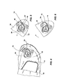
Figures 4-6 show schematic views, from a first side, of a movement device according to an embodiment of the present disclosure in successive operating conditions; -
Figure 7 shows a partial view, on a larger scale, from a first side, of a movement device according to an embodiment of the present disclosure; -
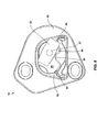
Figure 8 shows a view, on a larger scale, from a second side, of a movement device according to an embodiment of the present disclosure in an operating condition; -
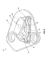
Figure 9 shows a further view, on a larger scale, from a second side, of a movement device according to an embodiment of the present disclosure in an operating condition; -
Figure 10 shows an axonometric view of a helmet including a movement device according to an embodiment of the present disclosure associated with a ventilation opening. - With reference to the accompanying figures, the
reference number 10 denotes a movement device according to the present disclosure. - In particular, in the example shown in the figures, the
movement device 10 is applied to ahelmet 12 including ashell 14 protecting the head of a user and avisor 16. Themovement device 10 is intended to move thevisor 16 with respect to theshell 14 of thehelmet 12 by means of a rotational or pivoting movement about an axis X. - More particularly, two
movement devices 10, only one of which is visible inFigures 1-9 , are associated with thehelmet 12, said devices being arranged on opposite sides in so-called temple regions of a user's head, namely along the sides of thehelmet 12 which protect the temple zones of the user's head. The axis X extends between one temple region and another and is the same for both themovement devices 10. - In order to simplify illustration, in the continuation of the present description, only a
single movement device 10 is described, namely the device located in the right-hand zone of theshell 14, or in other words themovement device 10 located in the user's right-hand temple region. InFigures 1-7 themovement device 10 is viewed from the inner side of thehelmet 12, namely the side for connection to theshell 14, while inFigures 8-9 , themovement device 10 is viewed from the opposite side, namely from the side for connection to thevisor 16 on the outer side of thehelmet 12. - Each
movement device 10 is intended to displace thevisor 16 between a first operating position, or closed position, where saidvisor 16 is situated opposite the user's face and has a protective function, and a second operating position, where thevisor 16 is raised opposite the user's forehead. - It should be understood that the
movement device 10 may be associated with any other element of the helmet, such as a chin guard or a movable flap intended to close a ventilation opening. For exampleFigure 10 shows a helmet including amovable flap 116 intended to close a ventilation opening 115. Themovement device 10, which is located underneath theflap 116 and therefore is not visible, is intended to move themovable flap 116 between an open position and a closed position, in the same way as for thevisor 16. - In the continuation of the description, reference will be made in particular to the use of the
movement device 10 for moving the visor 16 (which represents said first element of the helmet) with respect to the shell 14 (which represents said second element of the helmet) only for the sake of simplifying illustration. - In the example shown, the
movement device 10 comprises abase body 20, or support base, integrally associated with theshell 14 of the helmet, for example by means ofscrews 21, and arranged inside on theshell 14, and apivot element 24 which is movable with respect to thebase body 20. - In particular, the
pivot element 24 includes afirst head portion 22 with a slender and oblong form, which is housed in apivot seat 25 formed in thebase body 20. In particular, thepivot seat 25 is a recess formed in thebase body 20 on one side or face of the base body. - In some embodiments, the
pivot element 24 and thebase body 20 are made of metallic materials in order to ensure adequate robustness. - In other embodiments, the
pivot element 24 and thebase body 20 are made, for example, of acetal resin, polycarbonate, ABS or similar materials which have a suitable mechanical strength. - The
pivot element 24 is stably associated with thevisor 16 and is rotationally integral therewith. The connection between thepivot element 24 and thevisor 16 is obtained in a known manner. - For connection to the
visor 16 thepivot element 24 comprises asecond head portion 23, opposite to thefirst head portion 22, in the example having a substantially rectangular form (seeFigures 8-9 ). - As can be seen in the drawings, the
pivot element 24 includes a rotating shaft, denoted generally by thenumber 27, coaxial with the axis of rotation X of thevisor 16, and an eccentric portion orcam 26 which is eccentric with respect to the axis X and associated with thefirst head portion 22. - With reference to
Figures 2 and3 , according to an aspect of the present disclosure, thepivot seat 25 acts as a counter-cam for theeccentric portion 26 and includes afirst seat region 30 adapted to receive saideccentric portion 26 and asecond seat region 32 adapted to receive saideccentric portion 26, wherein thefirst seat region 30 is in a position angularly offset and linearly translated with respect to saidsecond seat region 32. The angular offsetting of thefirst seat region 30 with respect to thesecond seat region 32 is denoted by "α" inFigure 3 and occurs around the axis of rotation X. The linear or transverse offsetting of thefirst seat region 30 with respect to thesecond seat region 32, which in the example shown occurs substantially in a horizontal plane, is denoted by "d" inFigure 3 . - Depending on said spatial relationship between the
first seat region 30 and thesecond seat region 32, a first position of thepivot element 24 corresponds to thefirst seat region 30, and a second position of thepivot element 24 corresponds to saidsecond seat region 32, such that said second position is a position rotated and translated with respect to said first position. - Even more particularly, in the example shown, the first position of the
pivot element 24, when theeccentric portion 26 is located in thefirst seat region 30, is designed so as to correspond to a position which is further forwards and angularly higher than the second position of thepivot element 24, when theeccentric portion 26 is in thesecond seat region 32. - It follows that, in the example shown, an open condition of the
visor 16 on the forehead (linearly advanced position) corresponds to the first position of thepivot element 24, when theeccentric portion 26 is located in thefirst seat region 30. A closed condition of the visor 16 (linearly retracted position flush with the shell 14) corresponds to the second position, when theeccentric portion 26 is located in thesecond seat region 32. - The correlation between the open position and the closed position of the
visor 16 and the positions of theeccentric portion 26 of thepivot element 24 in theseat 25 is visible inFigures 4-6 . - Even more particularly, in order to open or close the
visor 16, a user acts in the manner described below. - Initially, the
visor 16 is located, for example, in the open position on the forehead. Therefore, theeccentric portion 26 is located in thefirst seat region 30. - When the
visor 16 is lowered, theeccentric portion 26 passes from thefirst seat region 30 to thesecond seat region 32, and thepivot element 24 performs a rotation to compensate for angular offsetting between the twoseat regions seat regions - Consequently the
visor 16 is retracted towards the shell and in the closed position is located flush with theshell 14. - Vice versa, in order to open the
visor 16, theeccentric portion 26 passes from thesecond seat region 32 to thefirst seat region 30, and thepivot element 24 performs not only a rotation, but also a forwards translation so that the visor moves outwards beyond the volume of theshell 14. - With reference to
Figures 2 and3 , it can also be seen that thepivot seat 25 is substantially a recess formed in thebase body 20, on one face of thebase body 20. The recess defines a side wall oredge 35 in thebase body 20. - The
side edge 35 is suitably shaped to define thefirst seat region 30 and thesecond seat region 32, namely thefirst seat region 30 and thesecond seat region 32 are defined by shaping of theside edge 35 of thebase body 20. - The profile of the
side edge 35 is substantially concave/convex, with a flexion, i.e. has a depression/hump, between thefirst seat region 30 and thesecond seat region 32. In particular, theside edge 35 has a profile which is concave, namely defines a depression or groove, in thefirst seat region 30, and a profile which is slightly convex, namely defines a slight projection or hump, in thesecond seat region 32. - Owing to this concave/convex shape of the
side edge 35 of thebase body 20 it is possible to obtain a homogeneous and continuous rotary/translational movement of thepivot element 24. - With reference to
Figures 2 and3 , it can also be noted, moreover, that thefirst head portion 22 of thepivot element 24 comprises, in addition to theeccentric portion 26, an eccentric projectingappendage 36 which is arranged on the substantially opposite side of the axis X to theeccentric portion 36 and interacts with further seat regions of theseat 25. - This
appendage 36 has the function of interacting with theside edge 35 of thebase body 20 both to guide displacement of the pivot element 34 from the second (retracted) position to the first (advanced) position and to define a so-called end-of-travel stop for the movement of thepivot element 24 into the two positions. In particular, theseat 25 comprises on the substantially opposite side of the axis of rotation X, athird seat region 40 intended to receive theeccentric appendage 36, when theeccentric portion 26 is located in thesecond seat region 32, and afourth seat region 42 intended to receive theeccentric appendage 36, when theeccentric portion 26 is located in thefirst seat region 30. - The
third seat region 40 and thefourth seat region 42 are also defined by a concave shaping of theedge 35. In fact theedge 35 has respective concave depressions with the formation ofshoulders third seat region 40 andfourth seat region 42, saidshoulders edge 35 situated between thethird seat region 40 and thefourth seat region 42 is shaped so as to obtain a linear displacement of thepivot element 42 when it is moved from the second (retracted) position to the first (advanced) position. - With reference to
Figures 7-9 , it can also be seen that themovement device 10 includes aretainer assembly 50 for retaining thepivot element 24 in the first position or in the second position, preventing undesirable movement of thepivot element 24 from the respective first position or second position. For this purpose, thebase body 20 comprises, on the side/face opposite to thepivot seat 25, acavity 51 which houses aspring 52, in the example an undulating linear spring. - Basically, the
base body 20 has on a first side or face thepivot seat 25 and, on the other side or face, thecavity 51 for theretainer assembly 50 and, in particular, in the example shown, for the linear undulatingspring 52. - The
spring 52 is defined by a suitable profile and, in the embodiment shown, comprises in particular three undulations, defining two correspondinglateral humps central hump 54 and respective intermediate depressions and is positioned in thecavity 51 so as to be able to be flexed in a direction at right angles to the direction of the axis of rotation X of thepivot element 24. - The
spring 52 is able to interact with an interaction element which is associated with the pivot element and in the example of embodiment is atooth 56 having, in the example, a rounded profile. - The
tooth 56 and the linear undulatingspring 52 are relatively arranged and designed so that, when theeccentric portion 26 is located in thefirst seat region 30, thetooth 56 is stably housed in one of the two depressions between two humps, for example between the twohumps spring 52, and, when theeccentric portion 26 is located in thesecond seat region 32, thetooth 56 is stably housed in the other depression between the other two humps, for example between the twohumps spring 52. - Basically, the
tooth 56 acts as an interaction element and the spring as an interaction counter-element. The profile of thespring 56 thus allows the interaction element to be retained under normal conditions without forcing (namely when thevisor 16 of the helmet is immobile with respect to theshell 14 in the open and/or closed condition) both in the first position and in the second position and prevent undesirable movements of thevisor 16. Asingle spring 52 is thus used to keep thepivot element 24 fixed in the two positions. - In fact, when it is required to perform an opening and/or closing movement of the
visor 16 of the helmet, and thepivot element 24 is displaced between the first position and the second position and vice versa, the tooth passes from one position to the other, deforming the profile of the spring and counteracting the elastic force of the latter. Once passed over, owing to the elastic return movement of thespring 52, the latter is repositioned in the original position, retaining again thetooth 56 of thepivot element 24. - Owing to this elastic configuration of the retainer assembly, a soft and dampened movement of the visor may be obtained during the opening and closing operations.
- The movement device of the present disclosure has been described hitherto with reference to preferred embodiments thereof. It is understood that other embodiments relating to the same inventive idea may exist, all of these falling within the scope of protection of the claims which are provided hereinbelow.
Claims (19)
- Movement device (10) for a helmet (12) for moving a first element (16) of the helmet (12) with respect to a second element (14) of the helmet (12), wherein said movement device (10) includes a pivot element (24) for pivoting the first element (16) of the helmet with respect to the second element (14) of the helmet about an axis of rotation (X), and a seat (25) of rotation for the pivot element, the pivot element (24) being located at least partially in the seat, wherein said pivot element (24) includes an eccentric portion (26) or cam, and said seat (25) includes a first seat region (30) adapted to receive said eccentric portion (26) in a first position of the pivot element (24), and a second seat region (32) adapted to receive said eccentric portion (26) in a second position of the pivot element (24), wherein the first seat region (30) is in a position angularly offset around the axis of rotation (X) and linearly translated relative to the second seat region (32), such that the second position of the pivot element (24) is angularly offset around the axis of rotation (X) and linearly translated with respect to the first position of the pivot element (24), and vice versa.
- Movement device (10) according to claim 1, wherein the eccentric portion (26) is configured to cooperate with the seat (25) of rotation causing a displacement of the pivot element (24) from the first position to the second position, upon an angular displacement of the first element (16) with respect to the second element (14) about the axis of rotation (X).
- Movement device (10) according to claim 1 or 2, comprising a base body (20) fixed to the second element (14) of the helmet, wherein the base body (20) has a recess delimited by a side edge or wall (35), said recess defining said seat (25) for the pivot and acting as a counter-cam for said eccentric portion (26).
- Movement device (10) according to claim 3, wherein the edge or side wall (35) is shaped to define said first seat region (30) and said second seat region (32).
- Movement device (10) according to claim 4, wherein the side edge or wall (35) has a respective concave profile for defining said first seat region (30) and a convex profile for defining said second seat region (32).
- Movement device (10) according to any one of the preceding claims, wherein the pivot element (24) comprises an eccentric appendage (36) received in the seat (25) for the pivot element and adapted to be placed in further regions of the seat (25) of rotation, and wherein the eccentric appendage (36) is configured to cooperate with the seat (25) of rotation, causing a displacement of the pivot element (24) from the second position to the first position upon an angular displacement of the first element (16) with respect to the second element (14) about the axis of rotation (X).
- Movement device (10) according to claim 6, wherein the pivot seat (25) comprises a third seat region (40) intended to receive the eccentric appendage (36), when the first eccentric portion (26) is located in the second seat region (32), and a fourth seat region (42) intended to receive the eccentric appendage (36), when the first eccentric portion (26) is located in the first seat region (30).
- Movement device (10) according to claim 7, in combination with claim 3, 4 or 5, wherein the side edge (35) defining the seat (25) defines a first shoulder (45) in the third seat region (40), with an end-of-travel function for the second eccentric portion (36), and a second shoulder (46) in the fourth seat region (42), with an end-of-travel function.
- Movement device (10) according to any one of the preceding claims, comprising a retainer assembly (50) for retaining the pivot element (24) in the first position and/or in the second position, said retainer assembly (50) including an interaction element (56) associated with the pivot element (24) and at least one interaction counter-element (52, 54) associated with the seat (25) for the pivot.
- Movement device (10) according to claim 9, wherein either one of and/or both the interaction element and the interaction counter-element is/are an elastically deformable element.
- Movement device (10) according to claim 9, wherein the interaction element is a tooth (56) and the interaction counter-element comprises a spring (52) and wherein the tooth (56) is adapted to deform a profile of the spring counteracting an elastic force of the spring (52) upon passage of said pivot element (24) between the first position and the second position and vice versa, and wherein, when the pivot element (24) is in the first position and/or in the second position, the spring (56) is in an original rest position and retains the tooth (56) of the pivot element (24).
- Helmet (12) including a movement device (10) according to any one of the preceding claims 1 to 11.
- Helmet (12) according to claim 12, including a visor (16) and/or a chin guard, wherein the visor (16) or the chin guard is said first element of the helmet.
- Helmet (12) according to claim 12, including a movable flap (116) adapted to close a ventilation opening (115), wherein said movable flap (116) is said first element of the helmet.
- Method for moving a first element (16) of a helmet with respect to a second element (14) of the helmet, said method comprising the steps of- associating a pivot element (24) with the first element (16), wherein said pivot element (24) includes an eccentric portion (26) eccentric with respect to a rotational axis (X) of the pivot;- associating a seat (25) of rotation for the pivot with the second element (14), wherein said seat for the pivot includes a first seat region (30) adapted to receive said eccentric portion (26) and a second seat region (32) adapted to receive said eccentric portion (26), and wherein said second seat region (32) is linearly translated and angularly offset around the axis of rotation (X) with respect to the first seat region (30);- positioning the pivot element (24) at least partially in the seat (25) in a first position where the eccentric portion (26) is located in the first seat region (30);- moving the pivot element (24) in a second position where the eccentric portion (26) is located in the second seat region (32);
wherein, when the eccentric portion (26) of the pivot element (24) passes from the first seat region (30) to the second seat region (32) or vice versa, the pivot element (24) performs both a rotation to compensate for angular offsetting between the second seat region (32) and the first seat region (30) and a linear displacement to compensate for linear offsetting between the second seat region (32) and the first seat region (30). - Method according to claim 15, wherein the linear displacement is a forward or backward movement of the first element (16) of the helmet (12) with respect to the second element (14) of the helmet (12), for spacing apart or moving the first element (16) of the helmet (12) respectively away from/towards the second element (14) of the helmet (12).
- Method according to claim 15 or 16, wherein the first element (16) of the helmet is a visor (16), a chin guard or a movable flap (116) of the helmet, and wherein, when the eccentric portion (26) is located in the first seat region (30), the first position corresponds to an open condition of the visor (16), the chin guard or the movable flap (116) and wherein, when the eccentric portion (26) is located in the second seat region (32), the second position corresponds to a closed condition of the visor (16), the chin guard or the movable flap (116).
- Method according to any one of claims 15 to 17, wherein the eccentric portion (26) moves between said first seat region (30) and said second seat region (32) by means of interaction with a side edge (35) of the seat (25), said side edge (35) being shaped to define the first seat region (30) and the second seat region (32).
- Method according to any one of the preceding claims 15 to 18, wherein the pivot element (24) is retained in said first position and/or in said second position by interaction between an interaction element (56) associated with the pivot element (24) and an interaction counter-element (52, 54) associated with the pivot seat (25), and wherein either one of and/or both said interaction element (56) and interaction counter-element (56) is/are elastically deformable elements such that when the pivot element (24) passes from the first position to the second position or vice versa, either one of and/or both said interaction element (56) and interaction counter-element (52, 54) is/are subject to an elastic deformation.
Applications Claiming Priority (1)
| Application Number | Priority Date | Filing Date | Title |
|---|---|---|---|
| IT000022A ITVR20120022A1 (en) | 2012-02-20 | 2012-02-20 | HANDLING DEVICE FOR A HELMET TO MOVE A FIRST ELEMENT OF THE HELMET COMPARED TO A SECOND HELMET ELEMENT. |
Publications (2)
| Publication Number | Publication Date |
|---|---|
| EP2628402A1 true EP2628402A1 (en) | 2013-08-21 |
| EP2628402B1 EP2628402B1 (en) | 2017-01-04 |
Family
ID=46001648
Family Applications (1)
| Application Number | Title | Priority Date | Filing Date |
|---|---|---|---|
| EP13155795.1A Active EP2628402B1 (en) | 2012-02-20 | 2013-02-19 | Helmet with a movement device for moving a first element of the helmet with respect to a second element of the helmet. |
Country Status (3)
| Country | Link |
|---|---|
| US (1) | US20130212785A1 (en) |
| EP (1) | EP2628402B1 (en) |
| IT (1) | ITVR20120022A1 (en) |
Cited By (2)
| Publication number | Priority date | Publication date | Assignee | Title |
|---|---|---|---|---|
| EP2578099A3 (en) * | 2011-10-03 | 2015-02-25 | Shoei Co., Ltd. | Helmet |
| WO2020079397A1 (en) | 2018-10-16 | 2020-04-23 | Jsp Limited | Visor carrier assembly |
Families Citing this family (6)
| Publication number | Priority date | Publication date | Assignee | Title |
|---|---|---|---|---|
| US20150074875A1 (en) * | 2011-12-19 | 2015-03-19 | Oliver Schimpf | Protective helmet; method for reducing or preventing a head injury |
| EP2853168B1 (en) * | 2013-09-26 | 2016-09-21 | Strategic Sports Limited | Helmet with pivotable shield |
| EP3459377A1 (en) | 2017-09-22 | 2019-03-27 | 3M Innovative Properties Company | Welding helmet |
| US11213089B2 (en) | 2019-06-04 | 2022-01-04 | Msa Technology, Llc | Protective helmet with face protection shield and linkage mechanism |
| US11583026B2 (en) * | 2021-02-09 | 2023-02-21 | LIFT Airborne Technologies LLC | Automatic visor locking system |
| US20260123707A1 (en) * | 2024-11-05 | 2026-05-07 | Polaris Industries Inc. | Systems and methods for helmet |
Citations (2)
| Publication number | Priority date | Publication date | Assignee | Title |
|---|---|---|---|---|
| US4748696A (en) * | 1986-05-16 | 1988-06-07 | Foehl Artur | Safety helmet |
| EP0534748A1 (en) * | 1991-09-25 | 1993-03-31 | Helmets Limited | Helmets |
Family Cites Families (27)
| Publication number | Priority date | Publication date | Assignee | Title |
|---|---|---|---|---|
| US4305160A (en) * | 1980-02-19 | 1981-12-15 | Bell Helmets, Inc. | Detent controlled helmet shields |
| WO1988003766A1 (en) * | 1986-11-17 | 1988-06-02 | Foehl Artur | Protective helmet with pivoting and engagable vizor, in particular for motorcyclists |
| JPH0647762B2 (en) * | 1990-10-24 | 1994-06-22 | 昭栄化工株式会社 | Shield plate mounting structure for helmet |
| US5297297A (en) * | 1993-04-02 | 1994-03-29 | Pei Pei Hsin | Automatic visor control device for helmets |
| JPH086202B2 (en) * | 1993-06-18 | 1996-01-24 | 昭栄化工株式会社 | Shield plate mounting structure for helmet |
| FR2724541B1 (en) * | 1994-09-20 | 1996-12-06 | Sextant Avionique | PAIR OF SYNCHRONIZED MANEUVER JOINTS FOR FIXING A RETRACTABLE VISOR ON A HELMET |
| JP3891623B2 (en) * | 1996-12-17 | 2007-03-14 | 株式会社Shoei | Helmet shield plate mounting mechanism |
| US6047409A (en) * | 1998-05-02 | 2000-04-11 | Simpson; Elwood J. B. | Adjustable safety lock for helmet face shield |
| US6557184B2 (en) * | 1999-05-27 | 2003-05-06 | Opticos, S.R.L. | Device for hooking the visor of a helmet for motorcycles |
| FR2817713B1 (en) * | 2000-12-12 | 2003-11-28 | Thomson Csf | FAST-DAY / NIGHT FOLDABLE VISOR HELMETS |
| JP3549490B2 (en) * | 2001-03-29 | 2004-08-04 | 株式会社アライヘルメット | Mounting structure of shield on helmet |
| JP4656756B2 (en) * | 2001-05-18 | 2011-03-23 | 株式会社Shoei | Helmet shield plate control device |
| KR100415341B1 (en) * | 2002-04-02 | 2004-01-16 | 주식회사 에이치제이씨 | Coupling Structur for Shied and Visor of Helmet |
| KR100427684B1 (en) * | 2002-05-31 | 2004-04-28 | 주식회사 에이치제이씨 | Coupling structur for helmet shield |
| ATE338481T1 (en) * | 2002-09-12 | 2006-09-15 | Opticos Srl | DEVICE FOR ATTACHING A VISOR TO A HELMET |
| US6732380B1 (en) * | 2003-02-27 | 2004-05-11 | Long Huei Helmet Co. | Fixing device for the windshield of a safety helmet |
| US7814579B2 (en) * | 2004-09-27 | 2010-10-19 | Kbc America, Inc. | Modular helmet |
| US7065798B2 (en) * | 2004-11-17 | 2006-06-27 | Kin Yong Lung Industrial Co., Ltd. | Helmet shield provided with positioning and adjusting device |
| TWM273977U (en) * | 2005-04-13 | 2005-09-01 | Bing-Jang Ye | Union structure of helmet lens and helmet body |
| ITMI20051839A1 (en) * | 2005-09-30 | 2007-04-01 | Opticos Srl | MONITORING CONTROL OF THE POSITION OF A VISOR FOR PROTECTIVE HELMETS |
| KR100659171B1 (en) * | 2005-12-15 | 2006-12-19 | 주식회사 홍진에이치제이씨 | Opening and closing mechanism of the jaw guard for helmet |
| US8069499B2 (en) * | 2006-05-15 | 2011-12-06 | Shoei Co., Ltd. | Helmet shield attaching mechanism, and helmet attached with the same |
| TW200836655A (en) * | 2007-03-05 | 2008-09-16 | Long Huei Helmet Co | Compounded safety helmet |
| US7895678B2 (en) * | 2007-08-06 | 2011-03-01 | Bell Sports, Inc. | Helmet with improved shield mount and precision shield control |
| KR100951343B1 (en) * | 2008-01-21 | 2010-04-08 | 주식회사 홍진에이치제이씨 | Helmet |
| US8051500B2 (en) * | 2008-09-12 | 2011-11-08 | Long Huei Helmet Co. | Safety helmet visor setting mechanism |
| US20110302701A1 (en) * | 2010-06-09 | 2011-12-15 | Kin Yung Lung Industrial Co., Ltd. | Position controlling mechanism for chin guard and visor plate of helmet |
-
2012
- 2012-02-20 IT IT000022A patent/ITVR20120022A1/en unknown
-
2013
- 2013-02-19 EP EP13155795.1A patent/EP2628402B1/en active Active
- 2013-02-19 US US13/770,730 patent/US20130212785A1/en not_active Abandoned
Patent Citations (2)
| Publication number | Priority date | Publication date | Assignee | Title |
|---|---|---|---|---|
| US4748696A (en) * | 1986-05-16 | 1988-06-07 | Foehl Artur | Safety helmet |
| EP0534748A1 (en) * | 1991-09-25 | 1993-03-31 | Helmets Limited | Helmets |
Cited By (6)
| Publication number | Priority date | Publication date | Assignee | Title |
|---|---|---|---|---|
| EP2578099A3 (en) * | 2011-10-03 | 2015-02-25 | Shoei Co., Ltd. | Helmet |
| WO2020079397A1 (en) | 2018-10-16 | 2020-04-23 | Jsp Limited | Visor carrier assembly |
| GB2579271A (en) * | 2018-10-16 | 2020-06-17 | Jsp Ltd | Visor carrier assembly |
| GB2579271B (en) * | 2018-10-16 | 2021-05-26 | Jsp Ltd | Visor carrier assembly |
| AU2019363349B2 (en) * | 2018-10-16 | 2021-08-19 | Jsp Limited | Visor carrier assembly |
| US11160323B2 (en) | 2018-10-16 | 2021-11-02 | Jsp Limited | Visor carrier assembly |
Also Published As
| Publication number | Publication date |
|---|---|
| US20130212785A1 (en) | 2013-08-22 |
| EP2628402B1 (en) | 2017-01-04 |
| ITVR20120022A1 (en) | 2013-08-21 |
Similar Documents
| Publication | Publication Date | Title |
|---|---|---|
| EP2628402B1 (en) | Helmet with a movement device for moving a first element of the helmet with respect to a second element of the helmet. | |
| CN113163888B (en) | Helmets with accessory attachment tracks | |
| US20200196698A1 (en) | Pivot-Arm Assembly for a Helmet Mounted Headset | |
| EP2578099B1 (en) | Helmet | |
| JP5733858B2 (en) | Visor mounting mechanism in helmet | |
| US10959477B2 (en) | Ear muff attachment having dual axis of rotation | |
| CN104093332B (en) | Protect the helmet and screen | |
| JP6148538B2 (en) | Helmet shield mounting mechanism | |
| EP4321048A1 (en) | Shield rotation controlling means | |
| KR102587766B1 (en) | Chin guard positioning assembly and helmet using the same | |
| JPH10168638A (en) | Helmet rotating plate mounting mechanism | |
| US10792974B2 (en) | Air register knob assembly | |
| EP3603434B1 (en) | Helmet | |
| EP3692847A1 (en) | Visor locking mechanism and helmet | |
| WO2013110675A1 (en) | Protective helmet and face-shield | |
| US8127375B2 (en) | Low profile helmet vents and venting system | |
| EP4520214A1 (en) | Rotation mechanism for helmet | |
| EP4410139A1 (en) | Rotating body fixing means for helmet | |
| CN203618852U (en) | Head size adjustment device for safety helmet | |
| JP2007332524A (en) | Helmet shield mounting mechanism | |
| CN213713487U (en) | Sliding door structure and air conditioner | |
| US10893969B2 (en) | Rear sheet adjustment assembly of neck collar | |
| CN217564937U (en) | Air regulating assembly and aerosol generating device | |
| CN115460491B (en) | A protective state switchable talker structure | |
| EP4483739A1 (en) | Locking means for chin guard |
Legal Events
| Date | Code | Title | Description |
|---|---|---|---|
| PUAI | Public reference made under article 153(3) epc to a published international application that has entered the european phase |
Free format text: ORIGINAL CODE: 0009012 |
|
| AK | Designated contracting states |
Kind code of ref document: A1 Designated state(s): AL AT BE BG CH CY CZ DE DK EE ES FI FR GB GR HR HU IE IS IT LI LT LU LV MC MK MT NL NO PL PT RO RS SE SI SK SM TR |
|
| AX | Request for extension of the european patent |
Extension state: BA ME |
|
| 17P | Request for examination filed |
Effective date: 20140219 |
|
| RBV | Designated contracting states (corrected) |
Designated state(s): AL AT BE BG CH CY CZ DE DK EE ES FI FR GB GR HR HU IE IS IT LI LT LU LV MC MK MT NL NO PL PT RO RS SE SI SK SM TR |
|
| GRAP | Despatch of communication of intention to grant a patent |
Free format text: ORIGINAL CODE: EPIDOSNIGR1 |
|
| INTG | Intention to grant announced |
Effective date: 20160722 |
|
| GRAS | Grant fee paid |
Free format text: ORIGINAL CODE: EPIDOSNIGR3 |
|
| STAA | Information on the status of an ep patent application or granted ep patent |
Free format text: STATUS: GRANT OF PATENT IS INTENDED |
|
| GRAA | (expected) grant |
Free format text: ORIGINAL CODE: 0009210 |
|
| STAA | Information on the status of an ep patent application or granted ep patent |
Free format text: STATUS: THE PATENT HAS BEEN GRANTED |
|
| AK | Designated contracting states |
Kind code of ref document: B1 Designated state(s): AL AT BE BG CH CY CZ DE DK EE ES FI FR GB GR HR HU IE IS IT LI LT LU LV MC MK MT NL NO PL PT RO RS SE SI SK SM TR |
|
| REG | Reference to a national code |
Ref country code: GB Ref legal event code: FG4D |
|
| REG | Reference to a national code |
Ref country code: CH Ref legal event code: EP |
|
| REG | Reference to a national code |
Ref country code: AT Ref legal event code: REF Ref document number: 858352 Country of ref document: AT Kind code of ref document: T Effective date: 20170115 |
|
| REG | Reference to a national code |
Ref country code: IE Ref legal event code: FG4D |
|
| REG | Reference to a national code |
Ref country code: DE Ref legal event code: R096 Ref document number: 602013016059 Country of ref document: DE |
|
| REG | Reference to a national code |
Ref country code: FR Ref legal event code: PLFP Year of fee payment: 5 |
|
| REG | Reference to a national code |
Ref country code: LT Ref legal event code: MG4D Ref country code: NL Ref legal event code: MP Effective date: 20170104 |
|
| PG25 | Lapsed in a contracting state [announced via postgrant information from national office to epo] |
Ref country code: BE Free format text: LAPSE BECAUSE OF NON-PAYMENT OF DUE FEES Effective date: 20170228 |
|
| REG | Reference to a national code |
Ref country code: AT Ref legal event code: MK05 Ref document number: 858352 Country of ref document: AT Kind code of ref document: T Effective date: 20170104 |
|
| PG25 | Lapsed in a contracting state [announced via postgrant information from national office to epo] |
Ref country code: NL Free format text: LAPSE BECAUSE OF FAILURE TO SUBMIT A TRANSLATION OF THE DESCRIPTION OR TO PAY THE FEE WITHIN THE PRESCRIBED TIME-LIMIT Effective date: 20170104 |
|
| PG25 | Lapsed in a contracting state [announced via postgrant information from national office to epo] |
Ref country code: NO Free format text: LAPSE BECAUSE OF FAILURE TO SUBMIT A TRANSLATION OF THE DESCRIPTION OR TO PAY THE FEE WITHIN THE PRESCRIBED TIME-LIMIT Effective date: 20170404 Ref country code: HR Free format text: LAPSE BECAUSE OF FAILURE TO SUBMIT A TRANSLATION OF THE DESCRIPTION OR TO PAY THE FEE WITHIN THE PRESCRIBED TIME-LIMIT Effective date: 20170104 Ref country code: FI Free format text: LAPSE BECAUSE OF FAILURE TO SUBMIT A TRANSLATION OF THE DESCRIPTION OR TO PAY THE FEE WITHIN THE PRESCRIBED TIME-LIMIT Effective date: 20170104 Ref country code: IS Free format text: LAPSE BECAUSE OF FAILURE TO SUBMIT A TRANSLATION OF THE DESCRIPTION OR TO PAY THE FEE WITHIN THE PRESCRIBED TIME-LIMIT Effective date: 20170504 Ref country code: LT Free format text: LAPSE BECAUSE OF FAILURE TO SUBMIT A TRANSLATION OF THE DESCRIPTION OR TO PAY THE FEE WITHIN THE PRESCRIBED TIME-LIMIT Effective date: 20170104 Ref country code: GR Free format text: LAPSE BECAUSE OF FAILURE TO SUBMIT A TRANSLATION OF THE DESCRIPTION OR TO PAY THE FEE WITHIN THE PRESCRIBED TIME-LIMIT Effective date: 20170405 |
|
| RAP2 | Party data changed (patent owner data changed or rights of a patent transferred) |
Owner name: DAINESE S.P.A. |
|
| PG25 | Lapsed in a contracting state [announced via postgrant information from national office to epo] |
Ref country code: PT Free format text: LAPSE BECAUSE OF FAILURE TO SUBMIT A TRANSLATION OF THE DESCRIPTION OR TO PAY THE FEE WITHIN THE PRESCRIBED TIME-LIMIT Effective date: 20170504 Ref country code: AT Free format text: LAPSE BECAUSE OF FAILURE TO SUBMIT A TRANSLATION OF THE DESCRIPTION OR TO PAY THE FEE WITHIN THE PRESCRIBED TIME-LIMIT Effective date: 20170104 Ref country code: BG Free format text: LAPSE BECAUSE OF FAILURE TO SUBMIT A TRANSLATION OF THE DESCRIPTION OR TO PAY THE FEE WITHIN THE PRESCRIBED TIME-LIMIT Effective date: 20170404 Ref country code: PL Free format text: LAPSE BECAUSE OF FAILURE TO SUBMIT A TRANSLATION OF THE DESCRIPTION OR TO PAY THE FEE WITHIN THE PRESCRIBED TIME-LIMIT Effective date: 20170104 Ref country code: ES Free format text: LAPSE BECAUSE OF FAILURE TO SUBMIT A TRANSLATION OF THE DESCRIPTION OR TO PAY THE FEE WITHIN THE PRESCRIBED TIME-LIMIT Effective date: 20170104 Ref country code: RS Free format text: LAPSE BECAUSE OF FAILURE TO SUBMIT A TRANSLATION OF THE DESCRIPTION OR TO PAY THE FEE WITHIN THE PRESCRIBED TIME-LIMIT Effective date: 20170104 Ref country code: SE Free format text: LAPSE BECAUSE OF FAILURE TO SUBMIT A TRANSLATION OF THE DESCRIPTION OR TO PAY THE FEE WITHIN THE PRESCRIBED TIME-LIMIT Effective date: 20170104 Ref country code: LV Free format text: LAPSE BECAUSE OF FAILURE TO SUBMIT A TRANSLATION OF THE DESCRIPTION OR TO PAY THE FEE WITHIN THE PRESCRIBED TIME-LIMIT Effective date: 20170104 |
|
| REG | Reference to a national code |
Ref country code: CH Ref legal event code: PL |
|
| REG | Reference to a national code |
Ref country code: DE Ref legal event code: R097 Ref document number: 602013016059 Country of ref document: DE |
|
| PG25 | Lapsed in a contracting state [announced via postgrant information from national office to epo] |
Ref country code: RO Free format text: LAPSE BECAUSE OF FAILURE TO SUBMIT A TRANSLATION OF THE DESCRIPTION OR TO PAY THE FEE WITHIN THE PRESCRIBED TIME-LIMIT Effective date: 20170104 Ref country code: EE Free format text: LAPSE BECAUSE OF FAILURE TO SUBMIT A TRANSLATION OF THE DESCRIPTION OR TO PAY THE FEE WITHIN THE PRESCRIBED TIME-LIMIT Effective date: 20170104 Ref country code: CH Free format text: LAPSE BECAUSE OF NON-PAYMENT OF DUE FEES Effective date: 20170228 Ref country code: SK Free format text: LAPSE BECAUSE OF FAILURE TO SUBMIT A TRANSLATION OF THE DESCRIPTION OR TO PAY THE FEE WITHIN THE PRESCRIBED TIME-LIMIT Effective date: 20170104 Ref country code: LI Free format text: LAPSE BECAUSE OF NON-PAYMENT OF DUE FEES Effective date: 20170228 Ref country code: CZ Free format text: LAPSE BECAUSE OF FAILURE TO SUBMIT A TRANSLATION OF THE DESCRIPTION OR TO PAY THE FEE WITHIN THE PRESCRIBED TIME-LIMIT Effective date: 20170104 |
|
| PLBE | No opposition filed within time limit |
Free format text: ORIGINAL CODE: 0009261 |
|
| STAA | Information on the status of an ep patent application or granted ep patent |
Free format text: STATUS: NO OPPOSITION FILED WITHIN TIME LIMIT |
|
| REG | Reference to a national code |
Ref country code: IE Ref legal event code: MM4A |
|
| PG25 | Lapsed in a contracting state [announced via postgrant information from national office to epo] |
Ref country code: MC Free format text: LAPSE BECAUSE OF FAILURE TO SUBMIT A TRANSLATION OF THE DESCRIPTION OR TO PAY THE FEE WITHIN THE PRESCRIBED TIME-LIMIT Effective date: 20170104 Ref country code: DK Free format text: LAPSE BECAUSE OF FAILURE TO SUBMIT A TRANSLATION OF THE DESCRIPTION OR TO PAY THE FEE WITHIN THE PRESCRIBED TIME-LIMIT Effective date: 20170104 Ref country code: SM Free format text: LAPSE BECAUSE OF FAILURE TO SUBMIT A TRANSLATION OF THE DESCRIPTION OR TO PAY THE FEE WITHIN THE PRESCRIBED TIME-LIMIT Effective date: 20170104 |
|
| 26N | No opposition filed |
Effective date: 20171005 |
|
| PG25 | Lapsed in a contracting state [announced via postgrant information from national office to epo] |
Ref country code: LU Free format text: LAPSE BECAUSE OF NON-PAYMENT OF DUE FEES Effective date: 20170219 |
|
| REG | Reference to a national code |
Ref country code: BE Ref legal event code: MM Effective date: 20170228 |
|
| PG25 | Lapsed in a contracting state [announced via postgrant information from national office to epo] |
Ref country code: IE Free format text: LAPSE BECAUSE OF NON-PAYMENT OF DUE FEES Effective date: 20170219 Ref country code: SI Free format text: LAPSE BECAUSE OF FAILURE TO SUBMIT A TRANSLATION OF THE DESCRIPTION OR TO PAY THE FEE WITHIN THE PRESCRIBED TIME-LIMIT Effective date: 20170104 |
|
| REG | Reference to a national code |
Ref country code: FR Ref legal event code: PLFP Year of fee payment: 6 |
|
| PG25 | Lapsed in a contracting state [announced via postgrant information from national office to epo] |
Ref country code: MT Free format text: LAPSE BECAUSE OF NON-PAYMENT OF DUE FEES Effective date: 20170219 |
|
| PG25 | Lapsed in a contracting state [announced via postgrant information from national office to epo] |
Ref country code: HU Free format text: LAPSE BECAUSE OF FAILURE TO SUBMIT A TRANSLATION OF THE DESCRIPTION OR TO PAY THE FEE WITHIN THE PRESCRIBED TIME-LIMIT; INVALID AB INITIO Effective date: 20130219 |
|
| PG25 | Lapsed in a contracting state [announced via postgrant information from national office to epo] |
Ref country code: CY Free format text: LAPSE BECAUSE OF NON-PAYMENT OF DUE FEES Effective date: 20170104 |
|
| PG25 | Lapsed in a contracting state [announced via postgrant information from national office to epo] |
Ref country code: MK Free format text: LAPSE BECAUSE OF FAILURE TO SUBMIT A TRANSLATION OF THE DESCRIPTION OR TO PAY THE FEE WITHIN THE PRESCRIBED TIME-LIMIT Effective date: 20170104 |
|
| PG25 | Lapsed in a contracting state [announced via postgrant information from national office to epo] |
Ref country code: TR Free format text: LAPSE BECAUSE OF FAILURE TO SUBMIT A TRANSLATION OF THE DESCRIPTION OR TO PAY THE FEE WITHIN THE PRESCRIBED TIME-LIMIT Effective date: 20170104 |
|
| PG25 | Lapsed in a contracting state [announced via postgrant information from national office to epo] |
Ref country code: AL Free format text: LAPSE BECAUSE OF FAILURE TO SUBMIT A TRANSLATION OF THE DESCRIPTION OR TO PAY THE FEE WITHIN THE PRESCRIBED TIME-LIMIT Effective date: 20170104 |
|
| REG | Reference to a national code |
Ref country code: GB Ref legal event code: 732E Free format text: REGISTERED BETWEEN 20210128 AND 20210203 |
|
| REG | Reference to a national code |
Ref country code: DE Ref legal event code: R082 Ref document number: 602013016059 Country of ref document: DE Ref country code: DE Ref legal event code: R081 Ref document number: 602013016059 Country of ref document: DE Owner name: DAINESE S.P.A., COLCERESA, IT Free format text: FORMER OWNER: AGV S.P.A., MOLVENA, VICENZA, IT |
|
| PGFP | Annual fee paid to national office [announced via postgrant information from national office to epo] |
Ref country code: GB Payment date: 20240219 Year of fee payment: 12 |
|
| GBPC | Gb: european patent ceased through non-payment of renewal fee |
Effective date: 20250219 |
|
| PG25 | Lapsed in a contracting state [announced via postgrant information from national office to epo] |
Ref country code: GB Free format text: LAPSE BECAUSE OF NON-PAYMENT OF DUE FEES Effective date: 20250219 |
|
| PGFP | Annual fee paid to national office [announced via postgrant information from national office to epo] |
Ref country code: DE Payment date: 20260218 Year of fee payment: 14 |
|
| PGFP | Annual fee paid to national office [announced via postgrant information from national office to epo] |
Ref country code: IT Payment date: 20260210 Year of fee payment: 14 |
|
| PGFP | Annual fee paid to national office [announced via postgrant information from national office to epo] |
Ref country code: FR Payment date: 20260218 Year of fee payment: 14 |