EP2628267B1 - A hearing device and a method of selecting an optimal transceiver channel in a wireless network - Google Patents
A hearing device and a method of selecting an optimal transceiver channel in a wireless network Download PDFInfo
- Publication number
- EP2628267B1 EP2628267B1 EP11769885.2A EP11769885A EP2628267B1 EP 2628267 B1 EP2628267 B1 EP 2628267B1 EP 11769885 A EP11769885 A EP 11769885A EP 2628267 B1 EP2628267 B1 EP 2628267B1
- Authority
- EP
- European Patent Office
- Prior art keywords
- frequency channel
- frequency
- optimal
- channel
- frequency channels
- Prior art date
- Legal status (The legal status is an assumption and is not a legal conclusion. Google has not performed a legal analysis and makes no representation as to the accuracy of the status listed.)
- Active
Links
Images



Classifications
-
- H—ELECTRICITY
- H04—ELECTRIC COMMUNICATION TECHNIQUE
- H04R—LOUDSPEAKERS, MICROPHONES, GRAMOPHONE PICK-UPS OR LIKE ACOUSTIC ELECTROMECHANICAL TRANSDUCERS; ELECTRIC HEARING AIDS; PUBLIC ADDRESS SYSTEMS
- H04R25/00—Electric hearing aids
- H04R25/50—Customised settings for obtaining desired overall acoustical characteristics
-
- H—ELECTRICITY
- H04—ELECTRIC COMMUNICATION TECHNIQUE
- H04L—TRANSMISSION OF DIGITAL INFORMATION, e.g. TELEGRAPHIC COMMUNICATION
- H04L1/00—Arrangements for detecting or preventing errors in the information received
- H04L1/0001—Systems modifying transmission characteristics according to link quality, e.g. power backoff
- H04L1/0033—Systems modifying transmission characteristics according to link quality, e.g. power backoff arrangements specific to the transmitter
-
- H—ELECTRICITY
- H04—ELECTRIC COMMUNICATION TECHNIQUE
- H04L—TRANSMISSION OF DIGITAL INFORMATION, e.g. TELEGRAPHIC COMMUNICATION
- H04L43/00—Arrangements for monitoring or testing data switching networks
- H04L43/08—Monitoring or testing based on specific metrics, e.g. QoS, energy consumption or environmental parameters
- H04L43/0823—Errors, e.g. transmission errors
-
- H—ELECTRICITY
- H04—ELECTRIC COMMUNICATION TECHNIQUE
- H04R—LOUDSPEAKERS, MICROPHONES, GRAMOPHONE PICK-UPS OR LIKE ACOUSTIC ELECTROMECHANICAL TRANSDUCERS; ELECTRIC HEARING AIDS; PUBLIC ADDRESS SYSTEMS
- H04R25/00—Electric hearing aids
- H04R25/55—Electric hearing aids using an external connection, either wireless or wired
- H04R25/552—Binaural
-
- H—ELECTRICITY
- H04—ELECTRIC COMMUNICATION TECHNIQUE
- H04R—LOUDSPEAKERS, MICROPHONES, GRAMOPHONE PICK-UPS OR LIKE ACOUSTIC ELECTROMECHANICAL TRANSDUCERS; ELECTRIC HEARING AIDS; PUBLIC ADDRESS SYSTEMS
- H04R25/00—Electric hearing aids
- H04R25/55—Electric hearing aids using an external connection, either wireless or wired
- H04R25/554—Electric hearing aids using an external connection, either wireless or wired using a wireless connection, e.g. between microphone and amplifier or using Tcoils
-
- H—ELECTRICITY
- H04—ELECTRIC COMMUNICATION TECHNIQUE
- H04W—WIRELESS COMMUNICATION NETWORKS
- H04W72/00—Local resource management
- H04W72/04—Wireless resource allocation
- H04W72/044—Wireless resource allocation based on the type of the allocated resource
- H04W72/0453—Resources in frequency domain, e.g. a carrier in FDMA
-
- H—ELECTRICITY
- H04—ELECTRIC COMMUNICATION TECHNIQUE
- H04W—WIRELESS COMMUNICATION NETWORKS
- H04W72/00—Local resource management
- H04W72/50—Allocation or scheduling criteria for wireless resources
- H04W72/54—Allocation or scheduling criteria for wireless resources based on quality criteria
- H04W72/542—Allocation or scheduling criteria for wireless resources based on quality criteria using measured or perceived quality
-
- H—ELECTRICITY
- H04—ELECTRIC COMMUNICATION TECHNIQUE
- H04R—LOUDSPEAKERS, MICROPHONES, GRAMOPHONE PICK-UPS OR LIKE ACOUSTIC ELECTROMECHANICAL TRANSDUCERS; ELECTRIC HEARING AIDS; PUBLIC ADDRESS SYSTEMS
- H04R2225/00—Details of deaf aids covered by H04R25/00, not provided for in any of its subgroups
- H04R2225/51—Aspects of antennas or their circuitry in or for hearing aids
Definitions
- the present specification relates to a hearing device adapted to select an optimal transceiver channel in a wireless network. Additionally, the present specification relates to a corresponding method.
- a wireless binaural hearing device system it may be advantageous to transfer data between the two hearing device via an optimal frequency channel, wherein the optimal frequency channel adapts to variations in the environment of the wireless binaural hearing device system.
- an object of the present invention is to select an optimal frequency channel for transmission of data between hearing devices in a binaural hearing device system.
- EP 1 220 499 discloses a wireless communication apparatus which performs wireless communication using a plurality of frequency channels.
- the apparatus includes a unit which detects an error rate of each of the plurality of frequency channels, a unit which determines whether the detected error rate is higher than a specific threshold value, and a unit which suspends use of a frequency channel whose error rate is determined to be higher than the threshold value.
- Luca Stabellini et al. "A new probabilistic approach for adaptive frequency hopping", IEEE 20th International symposion on personal, indoor and mobile radio communications (PIMRC 2009), IEEE, Piscataway, NJ, USA, 13 September 2009, pages 2147-2151, XP031660012, ISBN 978-1-4244-5122-7 relates to Utility Based Adaptive Frequency Hopping (UBAFH), an adaptive hopping technique implementing a new paradigm for frequency hopping systems.
- Traditional adaptive algorithms aim at identifying bad channels that are consequently removed from the hopset.
- UBAFH instead utilizes all the available frequencies but assigns different usage probabilities to different channels according to the experienced channel conditions. Opportune upper and lower limits are used in order to bound these usage probabilities and achieve a desired level of frequency diversity.
- US 2007/165754 discloses a method, terminal, and computer program to reduce radio interference in a wireless communications device having a combination of a wireless telephone unit, such as a GSM cellular phone, and a short range wireless communications unit, such as a WLAN communications unit or a Bluetooth communications unit.
- a wireless telephone unit such as a GSM cellular phone
- a short range wireless communications unit such as a WLAN communications unit or a Bluetooth communications unit.
- An interference avoidance subsystem in the wireless communications device is connected between the GSM frequency hopping logic and the Bluetooth frequency hopping logic.
- the Bluetooth frequency hopping logic changes the Bluetooth frequencies if the risk of interference is too high.
- the above and other objects are achieved by a method of receiving data on an optimal frequency channel in a wireless network comprising a plurality of frequency channels, according to the attached independent claim 1.
- the invention also relates to a corresponding hearing device apparatus, according to the attached independent claim 14.
- determining a frequency channel to be the optimal frequency channel may further comprise calculating a long term evaluation of each of the frequency channels based on the packet error rate of the respective frequency channels and a first time constant; and determining a frequency channel to be the optimal frequency channel based on the long term evaluation.
- a frequency channel which has been the optimal frequency channel over a long period of time e.g. 30 seconds may prove to be a better (more stable) choice for optimal frequency channel than a frequency channel which has only been the optimal frequency channel for a short period of time e.g. 1 second.
- the method may further comprise calculating a short term evaluation of each of the frequency channels based on the packet error rate of the respective frequency channels and a second time constant being smaller than the first time constant; and determining a frequency channel to be the optimal frequency channel based on the short term evaluation, e.g. if a plurality of frequency channels comprise an identical optimal long term evaluation.
- the optimal channel of this plurality of channels is the one having also optimal short term characteristic i.e. the frequency channel being the optimal most recently of the channels having long term optimal characteristics is chosen.
- the method may further comprise determining a frequency channel to be the optimal frequency channel based on a random selection from frequency channels having identical optimal short term and optimal long term evaluations.
- the method may further comprise determining an environment of the receiving participant based on the long term evaluation of the frequency channels and/or the short term evaluation of the frequency channels.
- the method may further comprise maintaining the optimal frequency channel as the optimal frequency channel if the packet error rate of the optimal channel is below a first threshold value or if the packet error rates of the frequency channels in the second subset is above a second threshold value.
- the method may further comprise transmitting an optimal frequency channel and a countdown value from the receiving participant to a transmitting participant, wherein said countdown value indicates to the receiving and transmitting participants when to switch to the optimal frequency channel.
- the method may further comprise transmitting high bandwidth data between the receiving participant and a transmitting participant in the second subset of the plurality of frequency channels.
- the high bandwidth data may be adapted to carry a real-time audio signal.
- the method may further comprise transmitting redundant data between the receiving participant and a transmitting participant in the first subset of the plurality of frequency channels.
- the method may further comprise excluding a frequency channel from the first and second subsets if the packet error rate of the frequency channel is above a third threshold value.
- the receiving participant may be a hearing device.
- Also disclosed is a method of selecting an optimal frequency channel in a wireless network comprising a plurality of frequency channels and a transmitting participant and a receiving participant, the method comprising utilizing redundant data to determine which of the plurality of frequency channels is the frequency channel with the lowest packet error rate.
- a hearing device comprising a transceiver and a digital signal processor adapted to perform the method as desclosed herein.
- the hearing device and embodiments thereof has the same advantages as the method of receiving data on an optimal frequency channel in a wireless network.
- a hearing device may be selected from the group consisting of a hearing aid, a hearing prosthesis, and the like.
- Examples of a hearing device may include a behind the ear (BTE) hearing aid and a in the ear (ITE) hearing aid.
- BTE behind the ear
- ITE in the ear
- a best and/or optimal frequency channel is to be understood as a frequency channel among a plurality of frequency channels in which optimal frequency channel packet error rate is the lowest of the plurality of frequency channels.
- Fig. 1 shows an embodiment of a hearing device system 100 comprising a first 110 hearing device and a second 120 device.
- the second 120 device may be selected from the group consisting of a second hearing device, a mobile telephone, a cordless telephone, a television, a fitting instrument fitting the first hearing device 110 to a user's hearing disability, and an intermediate device.
- the intermediate device may be a device communicating with the first hearing device 110 using a first communication protocol and with a third device (not shown) using another communication protocol.
- the intermediate device may communicate with the first hearing device 110 using a frequency band in the ISM frequency band and a Bluetooth-like protocol with low power requirements, and a Bluetooth protocol without low power requirements between the intermediate device and the third device.
- the first hearing device 110 may be a hearing aid
- the third device may be a Bluetooth enabled mobile telephone
- the intermediate device may provide communication between the hearing aid and the mobile telephone using the low power communication protocol to communicate with the hearing aid and a Bluetooth protocol to communicate with the mobile telephone.
- the first 110 hearing device and the second device 120 may be communicatively coupled via a wireless network 130 as disclosed below.
- the first hearing device 110 comprises one or more microphones 111 and at least one receiver 112. Additionally, the first hearing device 110 comprises a processing unit 113 such as a digital signal processor (DSP).
- the DSP 113 is communicatively coupled to the microphone 111 and the receiver 112.
- the communicative coupling may be embodied via electrical wires, a printed circuit board (PCB) or the like.
- the microphone 111 may receive an audio signal which is converted into a digital signal by an analog to digital converter (ADC).
- ADC analog to digital converter
- the digital signal is transmitted from the ADC to the DSP 113, thereby enabling the DSP to modify the digital signal to accommodate a hearing deficiency of a user of the hearing device 110.
- the modified digital signal may be transmitted from the DSP 113 to the receiver 112, which may convert the modified digital signal into a modified audio signal.
- the modified audio signal may be transmitted towards the tympanic membrane of the user.
- the hearing device 110 may comprise a memory device 115 such as a volatile or non-volatile memory device. Additionally, the hearing device 110 may comprise a detector 116 further described below. The detector 116 may be communicatively coupled to the memory device 115 via the PCB.
- the hearing device 110 and/or the second device 120 comprise respective communication units 114, 124 such as transceivers i.e. a combined transmitter and receiver.
- the hearing device 110 may comprise a transmitter 114 and the second 120 device a receiver 124 or vice versa.
- the hearing device 110 may comprise a transceiver 114 and the second 120 device a receiver 124 or vice versa.
- the respective communication units 114, 124 may be communicatively coupled to respective antennas, 117, 127 e.g. via the PCB.
- the hearing device 110 and the second device 120 may communicate via the respective communication units 114, 124 in order to establish the wireless network 130.
- the hearing device 110 and the second device 120 may communicate via the wireless network 130 using a number of frequency channels.
- the number of frequency channels may be 31 frequency channels.
- the number of frequency channels may be selected from the ISM (Industrial, Scientific and Medical) radio bands.
- one of the devices 110, 120 may act as a master and the other of the devices 110, 120 may act as a slave.
- Fig. 2 shows an embodiment in which the number of frequency channels (here 31 frequency channels) are selected from the frequency band ranging from 2.402 GHz to 2.480 GHz.
- other frequency bands may be used, e.g. other frequency bands in the ISM frequency band such as for example 902 MHz - 928 MHz.
- frequency bands outside the ISM frequency bands may be utilized.
- the frequency channels 1 to 31 may be selected randomly from the ISM frequency band e.g. from the 2.404 GHz - 2.478 GHz frequency band.
- the frequency distance between two adjacent frequency channels is approximately 22MHz in order to avoid interference from WLAN.
- data transmitted between the hearing device 110 and the second device 120 may be transmitted in slots.
- a slot may be 1.5 ms wide, and a slot may contain a frequency channel i.e. in a given slot one frequency channel may be utilized.
- data may be transmitted in a frame comprising 62 slots (slot 0 to slot 61).
- the device e.g. the second device 120 transmitting data to the other device (e.g. the first hearing device 110) may be referred to as the transmitting participant, and the other device may be referred to as the receiving participant.
- Fig. 2 additionally shows an embodiment of a frame in which the 62 slots and 31 frequency channels are correlated.
- a first subset e.g. a first number
- data is transmitted on a best frequency channel, which best frequency channel will be described in further details below.
- a second subset (e.g. a second number) of slots i.e. the remaining slots (every other second slot)
- the best frequency channel may be changes during a frame i.e. a frame may start out with a first frequency channel being the best frequency channel and later in the frame, the best frequency channel may be another frequency channel.
- the frequency channels in the second subset of slots, may be chosen sequentially e.g. by turn.
- the frequency channels in the second subset of slots may be chosen randomly with the premise that a chosen frequency channel cannot be chosen again for the current second subset of slots.
- B represent the best frequency channel
- X represents the frequency at which the best frequency channel B operates e.g. in the range 2.404 GHz - 2.480 GHz (but it could be in any range in the ISM frequency band).
- X may have different values during that frame.
- the hearing device 110 comprises a detector 116 detecting the data throughput for each frequency channel in the second subset of slots of a frame. Thereby, the hearing device 110 is able to detect which of the 31 frequency channels is the best.
- the detector monitors all 62 data slots in the frame, and collects the packet error rate for the first subset of slots and the second subset of slots separately. For the second subset the packet error rates are collected for each frequency channels i.e. 31 values. For the first subset the packet error rate has only one value i.e. best channel packet error rate. All the packet error rates are collected and stored with a time stamp in the memory 115 in order to enable the DSP to perform both long term (e.g. approximately thirty seconds) and short term evaluations (e.g. approximately 2 seconds) on the packet error rates. Thus, for each frequency channel, the DSP calculates a short term evaluation of the packet error rate e.g.
- the DSP stores the short term and long term evaluations for each frequency channel in the memory.
- thresholds may be introduced. If the packet error rate of the best channel (the first subset of frequency channels) is lower than a first threshold, or if the packet error rates of the monitor channels (i.e. the frequency channels in the second subset of frequency channels) are larger than a second threshold, then the best channel is maintained as the best frequency channel.
- the detector 116 selects another best channel from based on a frequency channel in the second subset having the lowest packet error rate in the long term evaluation.
- the DSP will select one frequency channel randomly from the plurality of frequency channels having the same lowest long term evaluation packet error rate and the same lowest short term evaluation packet error rate.
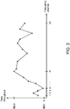
- Fig. 3 shows an example of a distribution of frequency channel throughput in which the abscissa comprises the 31 frequency channels (channel 1 to 31) and the ordinate comprises the data throughput (determined by the detector 116) ranging from a minimum (0) to a maximum (10 data units through).
- the detector may be a program being executed in the DSP 113 i.e. a software program being executed by the DSP 113 to provide the functionality of the detector described above.
- the detector 116 may be contained in the DSP 113.
- the detector 116 stores a time stamp with each frequency channel number and the corresponding packet throughput for the frequency channel at the given time in a first part of the memory device 115 of the hearing device 110. In a second and a third part of the memory device 115, the detector 116 stores a running average of each frequency channel number.
- the receiving participant may determine the best channel as described above. Subsequently, the receiving participant needs to inform the transmitting participant about the best channel on which the transmitting participant should transmit. This may be achieved by including information about the best channel into a header of a packet sent from the receiving participant to the transmitting participant.
- the header may further include a countdown value such as a number indicating in how may slots, the change to the best frequency should occur.
- the receiving participant may in a first slot transmit, on a frequency channel X (e.g. channel 2 of slot 2 in Fig. 2 ), in the header of a packet that the best frequency channel is frequency channel number Y (e.g. channel 24) and that the transmitting participant should switch to this best frequency channel in 10 slots.
- the receiving participant may in this slot transmit, on a frequency channel XX (where XX is the frequency channel of the next slot in the frame, e.g. frequency channel B of slot 3), in the header of a packet the best frequency channel is frequency channel number Y and that the transmitting participant should switch to this best frequency channel in 9 slots.
- the next slot e.g.
- the receiving participant may in the second slot transmit, on a frequency channel XXX (where XXX is the frequency channel of the next slot in the frame, e.g. frequency channel 3 of slot 4), in the header of a packet the best frequency channel is frequency channel number Y and that the transmitting participant should switch to this best frequency channel in 8 slots, and so on until the countdown value reaches zero (in slot 12 in this example).
- the transmitting participant and the receiving participant both switch to transmit and receive, respectively, on the best frequency channel (frequency channel Y in the example).
- the switch to the best channel Y occurs in the 11. frame after the receiving participants transmits the first slot indicating the best channel Y.
- the hearing device 110 may utilize the best channel, i.e. the first subset of slots discussed above, to transmit and/or receive audio data from the second device 120. Additionally, the second subset of slots (i.e. wherein all the 31 frequency channels are utilized) may be used to transmit and/or receive audio and/or less important data such as program number (e.g. of the hearing device 110), volume information of the transmitting participant, environmental information, and the like, to the receiving participant.
- program number e.g. of the hearing device 110
- the second device 120 may be another hearing device, and thus audio data may be transmitted between the two hearing aids (110, 120) using the best channel. Further, audio and/or less important data being transmitted a plurality of times, such as environmental information, program number, etc., may be transmitted using the frequency channels from the second subset (e.g. all the 31 channels in a 31 frequency channel system).
- redundant data i.e. less important data comprising little information and being transmitted a plurality of times, such as environmental information, program number, etc.
- redundant data may be utilized to determine which of the frequency channels (in the second subset of frequency channels) is the best channel.
- An effect of this is that the audio signal being transmitted on the best channels and which audio signal is important for a user is certain (or very close to certain) to be delivered from the transmitting participant to the receiving participant.
- less important data such as program number may be lost in some of the channels from the second subset, i.e. if one or more of these frequency channels are faulty, however due to redundancy in the less important data the information will reach the receiving participant e.g. when the best channel is used in the second subset of frequency channels.
- whether the less important data is reaching the receiving participant at the beginning or end or middle of the frame is not important because it only means a slip of e.g. 1ms in e.g. change of program number in the receiving participant.
- the hearing device 110 is adapted to exclude one or more frequency channels from the 31 frequency channels utilized in the second number of slots.
- one or more frequency channels may provide a low throughput due to the head shape of a user utilizing the hearing device 110.
- a user may for example have a head shape resulting in channel 4 (see Fig. 3 ) constantly providing a low data throughput.
- the hearing device 110 may be adapted to exclude this frequency channel from the frequency channels utilized in the second number of slots.
- the now empty slot may in one or more embodiments be utilized for another of the remaining 30 frequency channels or it may be utilized for transmitting audio or data over the best frequency channel.
- Fig. 4 shows an embodiment of a method of selecting an optimal transceiver channel.
- the method starts in step 500.
- step 505 the hearing device 110 (in this embodiment the receiving participant) resets or deletes the first and second and third parts of the memory device.
- step 510 communication between the hearing device 110 and the second device 120 (in this embodiment the transmitting participant) via the wireless network 130. Because no frequency channel has been detected as being the best frequency channel, data is transmitted on the 31 frequency channels in a first frame (the first 62 slots of data transmitted and/or received) in such a way that all the 31 frequency channels are utilized at least twice for the first frame.
- the frequency channels may be chosen sequentially e.g. by turn in the first frame. Alternatively, the frequency channels may be selected such that slot 0 and 1 comprises frequency channel 1, slot 2 and 3 contains frequency channel 2, etc., and slot 60 and 61 contains frequency channel 31.
- step 515 the detector 116 analyses the two times 31 frequency channels of the first frame to calculate the best channel of the first frame based on an average of the packet error rate in the two measurements obtained on each frequency channel.
- step 520 the detector stores the packet error rates of the frequency channels of the first frame together with a timestamp as disclosed above in a first part of the memory device 115.
- the detector 116 transmits via the communication unit 114, 124 and the antenna 117, 127 from the receiving participant to the transmitting participant the best channel frequency and a countdown value indicating when to switch to the best channel.
- step 530 when the countdown value reaches zero, the receiving participant and the transmitting participant switches to the best channel in the next slot.
- step 535 the detector stores the packet error rates of the frequency channels together with a timestamp as disclosed above in a first part of the memory device 115.
- step 540 the detector 116 analyses the long term evaluation and possibly the short term evaluation as described above of the frequency channels to determine the best channel.
- step 545 the detector 116 provides the resulting best channel and a countdown value to the receiving and transmitting participants if the analysis in step 540 indicates a change in best frequency channel.
- step 550 the method returns to step 530 until the transmission and reception of data between the receiving participant and the transmitting participant via the wireless network 130 has ended.
- step 555 the method ends.
- the hearing device 110 selects a frequency channel as the (initial) best frequency channel.
- the frequency channel may be selected randomly from the 31 frequency channels.
- the method and device are adapted to select a plurality of optimal transceiver channels.
- the packet error rate may be embodied as RSSI, bit error rate, packet loss, and/or quality/strength of the frequency channel.
- the short term and long term evaluations may be associated with fading and interference of a frequency channel.
- the short term evaluation may be associated with short term fading and interference of a frequency channel and the long term evaluation may be associated with long term fading and interference of the frequency channel.
- the short term and long term evaluations may be associated with changes in environment.
- the short term and long term evaluations may be used to determine a type of environment in which a wearer of the hearing device according to an embodiment is. Examples of environments with different short term and/or long term evaluations may be an office environment, urban environment, suburban environment, class-room environment, etc. Such environment may provide changes to the long term evaluation i.e.
- Examples of environments with different short term evaluations may be a user wearing a hearing device according to the above or below turning his/hers head. Such a change i.e. from one head position to another, may lead to a change in short term evaluation e.g. short term fading and interference.
- the hearing device may be adapted to determine the environment in which the user of the hearing device is, based on the short term and/or long term evaluation.
- the hearing device may contain a table correlating certain values of the short term evaluation and/or the long term evaluation with certain types of environments.
- the below-mentioned high bandwidth data may be defined as data such as video and/or audio data which must be transmitted and received in an acceptable quality.
- data such as video and/or audio data which must be transmitted and received in an acceptable quality.
- an audio signal transmitted from a first hearing device to another hearing device must be of such a quality, that the user can recognize the audio signal in both hearing devices.
- the high bandwidth data may be embodied as data which must arrive from the transmitting participant to the receiving participant.
- low bandwidth data may be defined as data which may be transmitted with a certain time-lag such as program selection synchronization between two hearing devices or the like.
Landscapes
- Engineering & Computer Science (AREA)
- Signal Processing (AREA)
- Computer Networks & Wireless Communication (AREA)
- Quality & Reliability (AREA)
- Health & Medical Sciences (AREA)
- General Health & Medical Sciences (AREA)
- Neurosurgery (AREA)
- Otolaryngology (AREA)
- Physics & Mathematics (AREA)
- Acoustics & Sound (AREA)
- Environmental & Geological Engineering (AREA)
- Mobile Radio Communication Systems (AREA)
Description
- The present specification relates to a hearing device adapted to select an optimal transceiver channel in a wireless network. Additionally, the present specification relates to a corresponding method.
- In a wireless binaural hearing device system, it may be advantageous to transfer data between the two hearing device via an optimal frequency channel, wherein the optimal frequency channel adapts to variations in the environment of the wireless binaural hearing device system.
- Therefore, an object of the present invention is to select an optimal frequency channel for transmission of data between hearing devices in a binaural hearing device system.
-
EP 1 220 499 - Luca Stabellini et al.: "A new probabilistic approach for adaptive frequency hopping", IEEE 20th International symposion on personal, indoor and mobile radio communications (PIMRC 2009), IEEE, Piscataway, NJ, USA, 13 September 2009, pages 2147-2151, XP031660012, ISBN 978-1-4244-5122-7 relates to Utility Based Adaptive Frequency Hopping (UBAFH), an adaptive hopping technique implementing a new paradigm for frequency hopping systems. Traditional adaptive algorithms aim at identifying bad channels that are consequently removed from the hopset. UBAFH instead utilizes all the available frequencies but assigns different usage probabilities to different channels according to the experienced channel conditions. Opportune upper and lower limits are used in order to bound these usage probabilities and achieve a desired level of frequency diversity.
-
US 2007/165754 discloses a method, terminal, and computer program to reduce radio interference in a wireless communications device having a combination of a wireless telephone unit, such as a GSM cellular phone, and a short range wireless communications unit, such as a WLAN communications unit or a Bluetooth communications unit. An interference avoidance subsystem in the wireless communications device is connected between the GSM frequency hopping logic and the Bluetooth frequency hopping logic. The Bluetooth frequency hopping logic changes the Bluetooth frequencies if the risk of interference is too high. - The above and other objects are achieved by a method of receiving data on an optimal frequency channel in a wireless network comprising a plurality of frequency channels, according to the attached
independent claim 1. The invention also relates to a corresponding hearing device apparatus, according to the attached independent claim 14. - Further preferred embodiments are claimed by the dependent claims.
- In the method, determining a frequency channel to be the optimal frequency channel may further comprise calculating a long term evaluation of each of the frequency channels based on the packet error rate of the respective frequency channels and a first time constant; and determining a frequency channel to be the optimal frequency channel based on the long term evaluation.
- A frequency channel which has been the optimal frequency channel over a long period of time e.g. 30 seconds may prove to be a better (more stable) choice for optimal frequency channel than a frequency channel which has only been the optimal frequency channel for a short period of time e.g. 1 second.
- The method may further comprise calculating a short term evaluation of each of the frequency channels based on the packet error rate of the respective frequency channels and a second time constant being smaller than the first time constant; and determining a frequency channel to be the optimal frequency channel based on the short term evaluation, e.g. if a plurality of frequency channels comprise an identical optimal long term evaluation.
- Thus, if a plurality of frequency channel have the same optimal characteristics on a long time scale (30 seconds above), then the optimal channel of this plurality of channels is the one having also optimal short term characteristic i.e. the frequency channel being the optimal most recently of the channels having long term optimal characteristics is chosen.
- The method may further comprise determining a frequency channel to be the optimal frequency channel based on a random selection from frequency channels having identical optimal short term and optimal long term evaluations.
- The method may further comprise determining an environment of the receiving participant based on the long term evaluation of the frequency channels and/or the short term evaluation of the frequency channels.
- The method may further comprise maintaining the optimal frequency channel as the optimal frequency channel if the packet error rate of the optimal channel is below a first threshold value or if the packet error rates of the frequency channels in the second subset is above a second threshold value.
- The method may further comprise transmitting an optimal frequency channel and a countdown value from the receiving participant to a transmitting participant, wherein said countdown value indicates to the receiving and transmitting participants when to switch to the optimal frequency channel.
- Thereby it may advantageously be ensured that the receiving and transmitting participants switch to the same optimal frequency channel at the same time.
- The method may further comprise transmitting high bandwidth data between the receiving participant and a transmitting participant in the second subset of the plurality of frequency channels. The high bandwidth data may be adapted to carry a real-time audio signal.
- Thereby it may advantageously be ensured that audio data is transmitted on the optimal frequency channel i.e. maximizing the probability that the audio data will reach the receiving participant from the transmitting participant.
- The method may further comprise transmitting redundant data between the receiving participant and a transmitting participant in the first subset of the plurality of frequency channels.
- It is an advantage that if redundant data is used from scanning the plurality of frequency channels, then it is acceptable if some of the data does not reach the receiving participant from the transmitting participant.
- The method may further comprise excluding a frequency channel from the first and second subsets if the packet error rate of the frequency channel is above a third threshold value.
- Thereby is advantageously obtained that if a frequency channel is permanently in disorder, then there is no reason in utilizing it and it may be replaced by another frequency channel thereby optimizing throughput between the transmitting and receiving participant and/or providing better statistical data on which the optimal frequency channel has to be chosen.
- The receiving participant may be a hearing device.
- Also disclosed is a method of selecting an optimal frequency channel in a wireless network comprising a plurality of frequency channels and a transmitting participant and a receiving participant, the method comprising utilizing redundant data to determine which of the plurality of frequency channels is the frequency channel with the lowest packet error rate.
- Also disclosed herein is a hearing device comprising a transceiver and a digital signal processor adapted to perform the method as desclosed herein.
- The hearing device and embodiments thereof has the same advantages as the method of receiving data on an optimal frequency channel in a wireless network.
- Further advantages and further embodiments of the invention are disclosed below.
-
-
Fig. 1 shows an embodiment of a hearing device system comprising a first hearing device and a second device. -
Fig. 2 shows an embodiment of a frame, frequency channels and frequencies utilized for the frequency channels. -
Fig. 3 shows an example of a distribution of frequency channel throughput of the frequency channels in a wireless network. -
Fig. 4 shows an embodiment of a method of selecting an optimal transceiver channel in a wireless network. - In the above and below, a hearing device may be selected from the group consisting of a hearing aid, a hearing prosthesis, and the like. Examples of a hearing device may include a behind the ear (BTE) hearing aid and a in the ear (ITE) hearing aid.
- Below and above, a best and/or optimal frequency channel is to be understood as a frequency channel among a plurality of frequency channels in which optimal frequency channel packet error rate is the lowest of the plurality of frequency channels.
-
Fig. 1 shows an embodiment of ahearing device system 100 comprising a first 110 hearing device and a second 120 device. - In one or more embodiments, the second 120 device may be selected from the group consisting of a second hearing device, a mobile telephone, a cordless telephone, a television, a fitting instrument fitting the
first hearing device 110 to a user's hearing disability, and an intermediate device. - In one or more embodiments, the intermediate device may be a device communicating with the
first hearing device 110 using a first communication protocol and with a third device (not shown) using another communication protocol. For example, the intermediate device may communicate with thefirst hearing device 110 using a frequency band in the ISM frequency band and a Bluetooth-like protocol with low power requirements, and a Bluetooth protocol without low power requirements between the intermediate device and the third device. For example, thefirst hearing device 110 may be a hearing aid, and the third device may be a Bluetooth enabled mobile telephone, and the intermediate device may provide communication between the hearing aid and the mobile telephone using the low power communication protocol to communicate with the hearing aid and a Bluetooth protocol to communicate with the mobile telephone.. - The first 110 hearing device and the
second device 120 may be communicatively coupled via awireless network 130 as disclosed below. - The
first hearing device 110 comprises one ormore microphones 111 and at least onereceiver 112. Additionally, thefirst hearing device 110 comprises aprocessing unit 113 such as a digital signal processor (DSP). The DSP 113 is communicatively coupled to themicrophone 111 and thereceiver 112. The communicative coupling may be embodied via electrical wires, a printed circuit board (PCB) or the like. - The
microphone 111 may receive an audio signal which is converted into a digital signal by an analog to digital converter (ADC). The digital signal is transmitted from the ADC to theDSP 113, thereby enabling the DSP to modify the digital signal to accommodate a hearing deficiency of a user of thehearing device 110. - The modified digital signal may be transmitted from the DSP 113 to the
receiver 112, which may convert the modified digital signal into a modified audio signal. The modified audio signal may be transmitted towards the tympanic membrane of the user. - The
hearing device 110 may comprise amemory device 115 such as a volatile or non-volatile memory device. Additionally, thehearing device 110 may comprise adetector 116 further described below. Thedetector 116 may be communicatively coupled to thememory device 115 via the PCB. - The
hearing device 110 and/or thesecond device 120 compriserespective communication units hearing device 110 may comprise atransmitter 114 and the second 120 device areceiver 124 or vice versa. In one or more embodiments, thehearing device 110 may comprise atransceiver 114 and the second 120 device areceiver 124 or vice versa. - The
respective communication units - The
hearing device 110 and thesecond device 120 may communicate via therespective communication units wireless network 130. - In one or more embodiments, the
hearing device 110 and thesecond device 120 may communicate via thewireless network 130 using a number of frequency channels. In one or more embodiments, the number of frequency channels may be 31 frequency channels. In one or more embodiments, the number of frequency channels may be selected from the ISM (Industrial, Scientific and Medical) radio bands. - In one or more embodiments, one of the
devices devices -
Fig. 2 shows an embodiment in which the number of frequency channels (here 31 frequency channels) are selected from the frequency band ranging from 2.402 GHz to 2.480 GHz. However, other frequency bands may be used, e.g. other frequency bands in the ISM frequency band such as for example 902 MHz - 928 MHz. In one or more embodiments, frequency bands outside the ISM frequency bands may be utilized. - In one or more embodiments, the
frequency channels 1 to 31 may be selected randomly from the ISM frequency band e.g. from the 2.404 GHz - 2.478 GHz frequency band. The frequency distance between two adjacent frequency channels is approximately 22MHz in order to avoid interference from WLAN. - In one or more embodiments, data transmitted between the
hearing device 110 and thesecond device 120 may be transmitted in slots. A slot may be 1.5 ms wide, and a slot may contain a frequency channel i.e. in a given slot one frequency channel may be utilized. In one or more embodiments, data may be transmitted in a frame comprising 62 slots (slot 0 to slot 61). - The device (e.g. the second device 120) transmitting data to the other device (e.g. the first hearing device 110) may be referred to as the transmitting participant, and the other device may be referred to as the receiving participant.
-
Fig. 2 additionally shows an embodiment of a frame in which the 62 slots and 31 frequency channels are correlated. In a first subset (e.g. a first number) of slots i.e. every second slot, data is transmitted on a best frequency channel, which best frequency channel will be described in further details below. - In a second subset (e.g. a second number) of slots i.e. the remaining slots (every other second slot), data is transmitted on one of the 31 frequency channels in such a way that all the 31 frequency channels are utilized at least once for every 62 slots i.e. the best frequency channel is utilized 32 times (in each of the first subset of slots = every other slot = 31 slots and once in the second subset of slots = 1 slot), and the other 30 frequency channels are utilized once each (once in the second subset of slots).
- In one or more embodiments, the best frequency channel may be changes during a frame i.e. a frame may start out with a first frequency channel being the best frequency channel and later in the frame, the best frequency channel may be another frequency channel.
- In one or more embodiments, in the second subset of slots, the frequency channels may be chosen sequentially e.g. by turn. In an alternative embodiment, the frequency channels in the second subset of slots may be chosen randomly with the premise that a chosen frequency channel cannot be chosen again for the current second subset of slots.
- In
Fig. 2 , B represent the best frequency channel, and X represents the frequency at which the best frequency channel B operates e.g. in the range 2.404 GHz - 2.480 GHz (but it could be in any range in the ISM frequency band). In the case where the optimal frequency channel is changed during a frame, X may have different values during that frame. - In one or more embodiments, the
hearing device 110 comprises adetector 116 detecting the data throughput for each frequency channel in the second subset of slots of a frame. Thereby, thehearing device 110 is able to detect which of the 31 frequency channels is the best. - In one or more embodiments, the detector monitors all 62 data slots in the frame, and collects the packet error rate for the first subset of slots and the second subset of slots separately. For the second subset the packet error rates are collected for each frequency channels i.e. 31 values. For the first subset the packet error rate has only one value i.e. best channel packet error rate. All the packet error rates are collected and stored with a time stamp in the
memory 115 in order to enable the DSP to perform both long term (e.g. approximately thirty seconds) and short term evaluations (e.g. approximately 2 seconds) on the packet error rates. Thus, for each frequency channel, the DSP calculates a short term evaluation of the packet error rate e.g. a running average over 2 seconds for each frequency channel and a long term evaluation of the packet error rate e.g. a running average over thirty seconds for each frequency channel. The short term and long term evaluations are updated substantially continuously i.e. each time a slot has been completed. The DSP stores the short term and long term evaluations for each frequency channel in the memory. - In one or more embodiments, thresholds may be introduced. If the packet error rate of the best channel (the first subset of frequency channels) is lower than a first threshold, or if the packet error rates of the monitor channels (i.e. the frequency channels in the second subset of frequency channels) are larger than a second threshold, then the best channel is maintained as the best frequency channel.
- Otherwise, the
detector 116 selects another best channel from based on a frequency channel in the second subset having the lowest packet error rate in the long term evaluation. - In one or more embodiments, if a plurality of frequency channels has the same lowest packet error rate in the long term evaluation, then the best frequency channel is selected by the DSP as the one frequency channel having the lowest packet error rate in the short term evaluation. If a plurality of frequency channels additionally has the same lowest packet error in the short term evaluation, then the DSP will select one frequency channel randomly from the plurality of frequency channels having the same lowest long term evaluation packet error rate and the same lowest short term evaluation packet error rate.
-
Fig. 3 shows an example of a distribution of frequency channel throughput in which the abscissa comprises the 31 frequency channels (channel 1 to 31) and the ordinate comprises the data throughput (determined by the detector 116) ranging from a minimum (0) to a maximum (10 data units through). - In one or more embodiments, the detector may be a program being executed in the
DSP 113 i.e. a software program being executed by theDSP 113 to provide the functionality of the detector described above. Thereby, thedetector 116 may be contained in theDSP 113. - The
detector 116 stores a time stamp with each frequency channel number and the corresponding packet throughput for the frequency channel at the given time in a first part of thememory device 115 of thehearing device 110. In a second and a third part of thememory device 115, thedetector 116 stores a running average of each frequency channel number. The running average in the second part may for each frequency channel contain the long term evaluation i.e. this running average is for each frequency channel calculated as

- In one or more embodiments, the receiving participant may determine the best channel as described above. Subsequently, the receiving participant needs to inform the transmitting participant about the best channel on which the transmitting participant should transmit. This may be achieved by including information about the best channel into a header of a packet sent from the receiving participant to the transmitting participant. In an additional embodiment, the header may further include a countdown value such as a number indicating in how may slots, the change to the best frequency should occur.
- In an example, the receiving participant may in a first slot transmit, on a frequency channel X (
e.g. channel 2 ofslot 2 inFig. 2 ), in the header of a packet that the best frequency channel is frequency channel number Y (e.g. channel 24) and that the transmitting participant should switch to this best frequency channel in 10 slots. In the next slot (e.g. slot 3), the receiving participant may in this slot transmit, on a frequency channel XX (where XX is the frequency channel of the next slot in the frame, e.g. frequency channel B of slot 3), in the header of a packet the best frequency channel is frequency channel number Y and that the transmitting participant should switch to this best frequency channel in 9 slots. In the next slot (e.g. slot 4), the receiving participant may in the second slot transmit, on a frequency channel XXX (where XXX is the frequency channel of the next slot in the frame,e.g. frequency channel 3 of slot 4), in the header of a packet the best frequency channel is frequency channel number Y and that the transmitting participant should switch to this best frequency channel in 8 slots, and so on until the countdown value reaches zero (in slot 12 in this example). In the slot following the slot in which the countdown value reaches zero (slot 13 in this example), the transmitting participant and the receiving participant both switch to transmit and receive, respectively, on the best frequency channel (frequency channel Y in the example). In the above example with a countdown value of 10, the switch to the best channel Y occurs in the 11. frame after the receiving participants transmits the first slot indicating the best channel Y. - In one or more embodiments, the
hearing device 110 may utilize the best channel, i.e. the first subset of slots discussed above, to transmit and/or receive audio data from thesecond device 120. Additionally, the second subset of slots (i.e. wherein all the 31 frequency channels are utilized) may be used to transmit and/or receive audio and/or less important data such as program number (e.g. of the hearing device 110), volume information of the transmitting participant, environmental information, and the like, to the receiving participant. - In an example, the
second device 120 may be another hearing device, and thus audio data may be transmitted between the two hearing aids (110, 120) using the best channel. Further, audio and/or less important data being transmitted a plurality of times, such as environmental information, program number, etc., may be transmitted using the frequency channels from the second subset (e.g. all the 31 channels in a 31 frequency channel system). - Thus, redundant data (i.e. less important data comprising little information and being transmitted a plurality of times, such as environmental information, program number, etc.) may be utilized to determine which of the frequency channels (in the second subset of frequency channels) is the best channel. An effect of this is that the audio signal being transmitted on the best channels and which audio signal is important for a user is certain (or very close to certain) to be delivered from the transmitting participant to the receiving participant. Likewise, less important data such as program number may be lost in some of the channels from the second subset, i.e. if one or more of these frequency channels are faulty, however due to redundancy in the less important data the information will reach the receiving participant e.g. when the best channel is used in the second subset of frequency channels. Further, whether the less important data is reaching the receiving participant at the beginning or end or middle of the frame is not important because it only means a slip of e.g. 1ms in e.g. change of program number in the receiving participant.
- In one or more embodiments, the
hearing device 110 is adapted to exclude one or more frequency channels from the 31 frequency channels utilized in the second number of slots. For example, one or more frequency channels may provide a low throughput due to the head shape of a user utilizing thehearing device 110. A user may for example have a head shape resulting in channel 4 (seeFig. 3 ) constantly providing a low data throughput. Thereby, thehearing device 110 may be adapted to exclude this frequency channel from the frequency channels utilized in the second number of slots. Instead, the now empty slot may in one or more embodiments be utilized for another of the remaining 30 frequency channels or it may be utilized for transmitting audio or data over the best frequency channel. -
Fig. 4 shows an embodiment of a method of selecting an optimal transceiver channel. - The method starts in
step 500. - In
step 505, the hearing device 110 (in this embodiment the receiving participant) resets or deletes the first and second and third parts of the memory device. - In
step 510, communication between thehearing device 110 and the second device 120 (in this embodiment the transmitting participant) via thewireless network 130. Because no frequency channel has been detected as being the best frequency channel, data is transmitted on the 31 frequency channels in a first frame (the first 62 slots of data transmitted and/or received) in such a way that all the 31 frequency channels are utilized at least twice for the first frame. The frequency channels may be chosen sequentially e.g. by turn in the first frame. Alternatively, the frequency channels may be selected such thatslot frequency channel 1,slot frequency channel 2, etc., andslot frequency channel 31. - In
step 515, thedetector 116 analyses the twotimes 31 frequency channels of the first frame to calculate the best channel of the first frame based on an average of the packet error rate in the two measurements obtained on each frequency channel. - In
step 520, the detector stores the packet error rates of the frequency channels of the first frame together with a timestamp as disclosed above in a first part of thememory device 115. - In
step 525, thedetector 116 transmits via thecommunication unit antenna - In
step 530, when the countdown value reaches zero, the receiving participant and the transmitting participant switches to the best channel in the next slot. - In
step 535, the detector stores the packet error rates of the frequency channels together with a timestamp as disclosed above in a first part of thememory device 115. - In
step 540, thedetector 116 analyses the long term evaluation and possibly the short term evaluation as described above of the frequency channels to determine the best channel. - In
step 545, thedetector 116 provides the resulting best channel and a countdown value to the receiving and transmitting participants if the analysis instep 540 indicates a change in best frequency channel. - In
step 550, the method returns to step 530 until the transmission and reception of data between the receiving participant and the transmitting participant via thewireless network 130 has ended. - In
step 555, the method ends. - As an alternative to step 510, the
hearing device 110 selects a frequency channel as the (initial) best frequency channel. The frequency channel may be selected randomly from the 31 frequency channels. - In an aspect of the invention, the method and device are adapted to select a plurality of optimal transceiver channels.
- In one or more embodiments, the packet error rate may be embodied as RSSI, bit error rate, packet loss, and/or quality/strength of the frequency channel.
- In one or more embodiments, the short term and long term evaluations may be associated with fading and interference of a frequency channel. In one or more embodiments, the short term evaluation may be associated with short term fading and interference of a frequency channel and the long term evaluation may be associated with long term fading and interference of the frequency channel. In an additional or alternative embodiment, the short term and long term evaluations may be associated with changes in environment. In one or more embodiments, the short term and long term evaluations may be used to determine a type of environment in which a wearer of the hearing device according to an embodiment is. Examples of environments with different short term and/or long term evaluations may be an office environment, urban environment, suburban environment, class-room environment, etc. Such environment may provide changes to the long term evaluation i.e. the long term fading and interference (and possibly also in the short term fading and interference). Examples of environments with different short term evaluations may be a user wearing a hearing device according to the above or below turning his/hers head. Such a change i.e. from one head position to another, may lead to a change in short term evaluation e.g. short term fading and interference.
- In one or more embodiments, the hearing device may be adapted to determine the environment in which the user of the hearing device is, based on the short term and/or long term evaluation. The hearing device may contain a table correlating certain values of the short term evaluation and/or the long term evaluation with certain types of environments.
- In one or more embodiments, the below-mentioned high bandwidth data may be defined as data such as video and/or audio data which must be transmitted and received in an acceptable quality. For example, an audio signal transmitted from a first hearing device to another hearing device must be of such a quality, that the user can recognize the audio signal in both hearing devices. Alternatively or additionally, the high bandwidth data may be embodied as data which must arrive from the transmitting participant to the receiving participant. In one or more embodiments, low bandwidth data may be defined as data which may be transmitted with a certain time-lag such as program selection synchronization between two hearing devices or the like.
Claims (14)
- A method of receiving data on an optimal frequency channel in a wireless network (130) comprising a plurality of frequency channels and a receiving participant (110), the method comprising• receiving data (510) on a first subset of a plurality of time slots; wherein each of the plurality of frequency channels except the current optimal frequency channel is utilized at least once;• receiving data (530) on a second subset of the plurality of time slots alternated with the time slots of the first subset; wherein the current optimal frequency channel is utilized;• determining (535) a packet error rate for each of the plurality of frequency channels in the first and the second subsets;• determining a frequency channel to be the optimal frequency channel based on the packet error rate.
- A method according to claim 1, wherein the determining a frequency channel to be the optimal frequency channel further comprises• calculating (540) a long term evaluation of each of the frequency channels based on the packet error rate of the respective frequency channels and a first time constant; and• determining (545) a frequency channel to be the optimal frequency channel based on the long term evaluation.
- A method according to claim 2, wherein the method further comprises• Calculating (540) a short term evaluation of each of the frequency channels based on the packet error rate of the respective frequency channels and a second time constant being smaller than the first time constant; and• determining (545) a frequency channel to be the optimal frequency channel based on the short term evaluation if a plurality of frequency channels comprise an identical optimal long term evaluation.
- A method according to claim 3, wherein the method further comprises• determining a frequency channel to be the optimal frequency channel based on a random selection from frequency channels having identical optimal short term and optimal long term evaluations.
- A method according to claim 3 or 4, further comprising• Determining an environment of the receiving participant based on the long term evaluation of the frequency channels and/or the short term evaluation of the frequency channels.
- A method according to anyone of the preceding claims, wherein the method further comprises maintaining the optimal frequency channel as the optimal frequency channel if the packet error rate of the optimal channel is below a first threshold value or if the packet error rates of the frequency channels in the second subset is above a second threshold value.
- A method according to anyone of the preceding claims, wherein the method further comprises transmitting an optimal frequency channel and a countdown value from the receiving participant to a transmitting participant, wherein said countdown value indicates to the receiving and transmitting participants when to switch to the optimal frequency channel.
- A method according to anyone of the preceding claims, wherein the method further comprises transmitting high bandwidth data between the receiving participant and a transmitting participant in the second subset of time slots.
- A method according to claim 8, wherein the high bandwidth data is adapted to carry a real-time audio signal.
- A method according to anyone of the preceding claims, wherein the method further comprises transmitting redundant data between the receiving participant and a transmitting participant in the first subset of time slots.
- A method according to anyone of the preceding claims, wherein the method further comprises excluding a frequency channel from the first and second subsets if the packet error rate of the frequency channel is above a third threshold value.
- A method according to anyone of the preceding claims, wherein the receiving participant is a hearing device.
- A method according to anyone of the preceding claims, further comprising selecting an optimal frequency channel in a wireless network comprising a plurality of frequency channels and a transmitting participant and a receiving participant, the method comprising• utilizing redundant data to determine which of the plurality of frequency channels is the frequency channel with the lowest packet error rate.
- A hearing device (110) comprising a transceiver (114) and a digital signal processor (113) adapted to perform the method according to anyone of claims 1 to 13.
Applications Claiming Priority (3)
| Application Number | Priority Date | Filing Date | Title |
|---|---|---|---|
| DKPA201000936 | 2010-10-14 | ||
| DKPA201100263 | 2011-04-06 | ||
| PCT/EP2011/067989 WO2012049292A1 (en) | 2010-10-14 | 2011-10-14 | A hearing device and a method of selecting an optimal transceiver channel in a wireless network |
Publications (2)
| Publication Number | Publication Date |
|---|---|
| EP2628267A1 EP2628267A1 (en) | 2013-08-21 |
| EP2628267B1 true EP2628267B1 (en) | 2019-09-25 |
Family
ID=44800051
Family Applications (1)
| Application Number | Title | Priority Date | Filing Date |
|---|---|---|---|
| EP11769885.2A Active EP2628267B1 (en) | 2010-10-14 | 2011-10-14 | A hearing device and a method of selecting an optimal transceiver channel in a wireless network |
Country Status (6)
| Country | Link |
|---|---|
| US (3) | US9894447B2 (en) |
| EP (1) | EP2628267B1 (en) |
| JP (1) | JP5723015B2 (en) |
| CN (1) | CN103155464B (en) |
| DK (1) | DK2628267T3 (en) |
| WO (1) | WO2012049292A1 (en) |
Families Citing this family (10)
| Publication number | Priority date | Publication date | Assignee | Title |
|---|---|---|---|---|
| CN103155464B (en) * | 2010-10-14 | 2016-05-11 | Gn瑞声达A/S | Hearing device and method for selecting an optimal transceiver channel in a wireless network |
| JP6599131B2 (en) * | 2014-05-20 | 2019-10-30 | ジーエヌ ヒアリング エー/エス | A new way to wirelessly transmit digital audio |
| US20160309482A1 (en) * | 2015-04-15 | 2016-10-20 | Qualcomm Incorporated | Interference-aware group owner, bandwidth, and channel selection in peer-to-peer wireless communication systems |
| EP3133838A1 (en) * | 2015-08-18 | 2017-02-22 | GN Resound A/S | A method of exchanging data packages between first and second portable communication devices using a favoured frequency band |
| US9831988B2 (en) | 2015-08-18 | 2017-11-28 | Gn Hearing A/S | Method of exchanging data packages between first and second portable communication devices |
| US9819705B2 (en) * | 2015-08-18 | 2017-11-14 | Gn Hearing A/S | Method of exchanging data packages between first and second portable communication devices using a favoured frequency band |
| US10003896B2 (en) | 2015-08-18 | 2018-06-19 | Gn Hearing A/S | Method of exchanging data packages of different sizes between first and second portable communication devices |
| US10045354B2 (en) * | 2016-03-24 | 2018-08-07 | Starkey Laboratories, Inc. | Adaptive channel mapping for wireless communications |
| JP6516784B2 (en) * | 2017-03-29 | 2019-05-22 | 本田技研工業株式会社 | Wireless communication apparatus and wireless communication system using the same |
| US12273684B2 (en) * | 2017-09-26 | 2025-04-08 | Cochlear Limited | Acoustic spot identification |
Family Cites Families (50)
| Publication number | Priority date | Publication date | Assignee | Title |
|---|---|---|---|---|
| US4864588A (en) | 1987-02-11 | 1989-09-05 | Hillier Technologies Limited Partnership | Remote control system, components and methods |
| DE4236982A1 (en) * | 1992-11-02 | 1994-05-05 | Philips Patentverwaltung | Cellular mobile radio system |
| US6400751B1 (en) | 1998-07-01 | 2002-06-04 | Itt Manufacturing Enterprises, Inc. | Adaptive frequency sharing method and apparatus |
| GB2344029A (en) | 1998-10-02 | 2000-05-24 | Gen Datacomm Adv Res | Transmission of data packets of different size and priority |
| US6651207B1 (en) * | 1999-08-20 | 2003-11-18 | Siemens Information & Communication Mobile, Llc | Method and system for improving voice quality in cordless communications |
| US7046644B1 (en) | 2000-11-27 | 2006-05-16 | Nokia Mobile Phones Ltd. | Adaptive transmission channel allocation method and system for ISM and unlicensed frequency bands |
| JP3443094B2 (en) * | 2000-12-27 | 2003-09-02 | 株式会社東芝 | Wireless communication method and wireless communication device |
| FI20010484L (en) | 2001-03-09 | 2002-09-10 | Nokia Corp | Data transmission system, data transmission device and method for performing data transmission |
| US7116699B2 (en) * | 2001-03-12 | 2006-10-03 | Texas Instruments Incorporated | Frequency re-mapping for structure adaptive frequency hopping |
| US20030081603A1 (en) * | 2001-10-26 | 2003-05-01 | Johan Rune | Pending data announcements |
| US8937928B2 (en) * | 2002-08-23 | 2015-01-20 | Koninklijke Philips N.V. | Frequency hopping in 5GHz WLAN via dynamic frequency selection |
| DE10304648B3 (en) | 2003-02-05 | 2004-08-19 | Siemens Audiologische Technik Gmbh | Device and method for communicating hearing aids |
| DE10320157B3 (en) | 2003-05-06 | 2004-11-11 | Infineon Technologies Ag | Channel transmission quality evaluation method for packet-based wireless communications system using actual data packet length and data packet error rate for received data packets |
| US7529565B2 (en) | 2004-04-08 | 2009-05-05 | Starkey Laboratories, Inc. | Wireless communication protocol |
| JP2005303583A (en) * | 2004-04-09 | 2005-10-27 | Matsushita Electric Ind Co Ltd | Wireless communication device |
| JP4449555B2 (en) | 2004-04-26 | 2010-04-14 | パナソニック株式会社 | Wireless communication apparatus and call channel switching method |
| US20050281277A1 (en) | 2004-06-22 | 2005-12-22 | Killian Thomas J | Establishing traffic priorities in a voice over IP network |
| GB2412815B (en) | 2004-08-18 | 2006-03-22 | Wecomm Ltd | Transmitting data over a network |
| CA2577397A1 (en) | 2004-08-18 | 2006-03-02 | Micro Ear Technology, Inc. D/B/A Micro-Tech | Wireless communications adapter for a hearing assistance device |
| US7483674B2 (en) | 2004-08-31 | 2009-01-27 | Telefonaktiebolaget L M Ericsson (Publ) | Providing robustness in fading radio channels |
| ES2330459T3 (en) | 2004-11-11 | 2009-12-10 | Koninklijke Philips Electronics N.V. | PRIORITY PROCEDURE BASED ON TAILS AND ASSEMBLY OF DATA PACKAGES. |
| US7684464B2 (en) | 2004-12-21 | 2010-03-23 | Qualcomm Incorporated | Method and apparatus for performing channel assessment in a wireless communication system |
| US8169938B2 (en) | 2005-06-05 | 2012-05-01 | Starkey Laboratories, Inc. | Communication system for wireless audio devices |
| WO2007015962A2 (en) * | 2005-07-27 | 2007-02-08 | T-Mobile, Usa, Inc. | Frequency band adaptive wireless communication |
| US7801620B2 (en) | 2005-08-29 | 2010-09-21 | Cardiac Pacemakers, Inc. | RF telemetry link quality assessment system and method |
| US20070165754A1 (en) * | 2006-01-17 | 2007-07-19 | Niko Kiukkonen | Method for avoiding interference from a cellular transmitter to the 2.4/5GHz ISM band |
| US20070291797A1 (en) | 2006-06-19 | 2007-12-20 | Rao Anil M | Method of packet data transmission |
| EP1883273A1 (en) | 2006-07-28 | 2008-01-30 | Siemens Audiologische Technik GmbH | Control device and method for wireless transmission of audio signals when programming a hearing aid |
| US20090111496A1 (en) | 2007-10-31 | 2009-04-30 | Brima Babatunde Ibrahim | Method and system for classifying bluetooth channels using a wideband receiver |
| US9083474B2 (en) * | 2008-04-25 | 2015-07-14 | Qualcomm Incorporated | Multimedia broadcast forwarding systems and methods |
| US8442248B2 (en) * | 2008-09-03 | 2013-05-14 | Starkey Laboratories, Inc. | Systems and methods for managing wireless communication links for hearing assistance devices |
| CN101431658B (en) * | 2008-12-01 | 2010-08-18 | 中兴通讯股份有限公司 | Channel selection method and device for mobile TV terminal |
| US8194902B2 (en) | 2008-12-22 | 2012-06-05 | Gn Resound A/S | Wireless network protocol for a hearing system |
| US9420385B2 (en) | 2009-12-21 | 2016-08-16 | Starkey Laboratories, Inc. | Low power intermittent messaging for hearing assistance devices |
| US8768252B2 (en) | 2010-09-02 | 2014-07-01 | Apple Inc. | Un-tethered wireless audio system |
| EP2947899B1 (en) | 2010-10-08 | 2017-12-13 | Oticon A/s | Wireless binaural hearing device |
| CN103155464B (en) * | 2010-10-14 | 2016-05-11 | Gn瑞声达A/S | Hearing device and method for selecting an optimal transceiver channel in a wireless network |
| US8849202B2 (en) | 2011-08-19 | 2014-09-30 | Apple Inc. | Audio transfer using the Bluetooth Low Energy standard |
| US9531501B2 (en) | 2011-10-25 | 2016-12-27 | Apple Inc. | Data transfer between electronic devices |
| US9967193B2 (en) | 2012-09-04 | 2018-05-08 | Pismo Labs Technology Limited | Method and system for increasing data flow transmission |
| US9826320B2 (en) | 2013-05-15 | 2017-11-21 | Gn Hearing A/S | Hearing device and a method for receiving wireless audio streaming |
| US9712266B2 (en) | 2013-05-21 | 2017-07-18 | Apple Inc. | Synchronization of multi-channel audio communicated over bluetooth low energy |
| US10075266B2 (en) | 2013-10-09 | 2018-09-11 | Qualcomm Incorporated | Data transmission scheme with unequal code block sizes |
| US9661425B2 (en) | 2014-01-15 | 2017-05-23 | Starkey Laboratories, Inc. | Method and apparatus for rendering audio in wireless hearing instruments |
| US10003379B2 (en) | 2014-05-06 | 2018-06-19 | Starkey Laboratories, Inc. | Wireless communication with probing bandwidth |
| US9693127B2 (en) | 2014-05-14 | 2017-06-27 | Samsung Electronics Co., Ltd | Method and apparatus for communicating audio data |
| US20150364143A1 (en) | 2014-06-12 | 2015-12-17 | Samsung Electronics Co., Ltd. | Method and apparatus for transmitting audio data |
| US9819705B2 (en) | 2015-08-18 | 2017-11-14 | Gn Hearing A/S | Method of exchanging data packages between first and second portable communication devices using a favoured frequency band |
| US9831988B2 (en) | 2015-08-18 | 2017-11-28 | Gn Hearing A/S | Method of exchanging data packages between first and second portable communication devices |
| US10003896B2 (en) | 2015-08-18 | 2018-06-19 | Gn Hearing A/S | Method of exchanging data packages of different sizes between first and second portable communication devices |
-
2011
- 2011-10-14 CN CN201180049825.7A patent/CN103155464B/en not_active Expired - Fee Related
- 2011-10-14 JP JP2013533231A patent/JP5723015B2/en not_active Expired - Fee Related
- 2011-10-14 DK DK11769885.2T patent/DK2628267T3/en active
- 2011-10-14 WO PCT/EP2011/067989 patent/WO2012049292A1/en not_active Ceased
- 2011-10-14 EP EP11769885.2A patent/EP2628267B1/en active Active
- 2011-10-14 US US13/825,966 patent/US9894447B2/en active Active
-
2017
- 2017-05-08 US US15/589,563 patent/US10313804B2/en active Active
-
2019
- 2019-05-31 US US16/428,679 patent/US11006224B2/en active Active
Non-Patent Citations (1)
| Title |
|---|
| None * |
Also Published As
| Publication number | Publication date |
|---|---|
| US9894447B2 (en) | 2018-02-13 |
| DK2628267T3 (en) | 2019-10-14 |
| US11006224B2 (en) | 2021-05-11 |
| US20170245291A1 (en) | 2017-08-24 |
| JP2013543328A (en) | 2013-11-28 |
| US20190289408A1 (en) | 2019-09-19 |
| WO2012049292A1 (en) | 2012-04-19 |
| US10313804B2 (en) | 2019-06-04 |
| CN103155464A (en) | 2013-06-12 |
| US20130279727A1 (en) | 2013-10-24 |
| JP5723015B2 (en) | 2015-05-27 |
| CN103155464B (en) | 2016-05-11 |
| EP2628267A1 (en) | 2013-08-21 |
Similar Documents
| Publication | Publication Date | Title |
|---|---|---|
| US11006224B2 (en) | Hearing device and a method of selecting an optimal transceiver channel in a wireless network | |
| US10623869B2 (en) | Hearing aid using wireless test modes as diagnostic tool | |
| EP2943026B1 (en) | Wireless communication with probing bandwith | |
| EP3211937B1 (en) | Method, apparatus, and computer program product for wireless short-range communication channel selection | |
| US6760317B1 (en) | Adaptive transmission channel allocation method and system for ISM and unlicensed frequency bands | |
| EP1475924B1 (en) | Wireless ad hoc communication with different power levels for message header and payload | |
| US7567531B2 (en) | Adaptive transmission channel allocation method and system for ISM and unlicensed frequency bands | |
| EP3288292A1 (en) | Hearing aid using wireless test modes as diagnostic tool | |
| EP3132544B1 (en) | Portable communication device with tunable antenna and method of operating such portable communication device | |
| JP2006217619A (en) | Method and apparatus for avoiding radio audio signal transmission interference | |
| EP3659351B1 (en) | Communication device with wireless interface using different protocols | |
| JP7333034B2 (en) | Wireless RF transmission method and wireless RF receiver | |
| US6611776B2 (en) | Signal quality measurement | |
| WO2004100461A1 (en) | Wireless ad hoc communication with different power levels for message header and payload |
Legal Events
| Date | Code | Title | Description |
|---|---|---|---|
| PUAI | Public reference made under article 153(3) epc to a published international application that has entered the european phase |
Free format text: ORIGINAL CODE: 0009012 |
|
| 17P | Request for examination filed |
Effective date: 20130514 |
|
| AK | Designated contracting states |
Kind code of ref document: A1 Designated state(s): AL AT BE BG CH CY CZ DE DK EE ES FI FR GB GR HR HU IE IS IT LI LT LU LV MC MK MT NL NO PL PT RO RS SE SI SK SM TR |
|
| DAX | Request for extension of the european patent (deleted) | ||
| STAA | Information on the status of an ep patent application or granted ep patent |
Free format text: STATUS: EXAMINATION IS IN PROGRESS |
|
| 17Q | First examination report despatched |
Effective date: 20180416 |
|
| GRAP | Despatch of communication of intention to grant a patent |
Free format text: ORIGINAL CODE: EPIDOSNIGR1 |
|
| STAA | Information on the status of an ep patent application or granted ep patent |
Free format text: STATUS: GRANT OF PATENT IS INTENDED |
|
| INTG | Intention to grant announced |
Effective date: 20190417 |
|
| GRAS | Grant fee paid |
Free format text: ORIGINAL CODE: EPIDOSNIGR3 |
|
| GRAA | (expected) grant |
Free format text: ORIGINAL CODE: 0009210 |
|
| STAA | Information on the status of an ep patent application or granted ep patent |
Free format text: STATUS: THE PATENT HAS BEEN GRANTED |
|
| RAP1 | Party data changed (applicant data changed or rights of an application transferred) |
Owner name: GN HEARING A/S |
|
| AK | Designated contracting states |
Kind code of ref document: B1 Designated state(s): AL AT BE BG CH CY CZ DE DK EE ES FI FR GB GR HR HU IE IS IT LI LT LU LV MC MK MT NL NO PL PT RO RS SE SI SK SM TR |
|
| REG | Reference to a national code |
Ref country code: GB Ref legal event code: FG4D |
|
| REG | Reference to a national code |
Ref country code: CH Ref legal event code: EP |
|
| REG | Reference to a national code |
Ref country code: DE Ref legal event code: R096 Ref document number: 602011062328 Country of ref document: DE |
|
| REG | Reference to a national code |
Ref country code: DK Ref legal event code: T3 Effective date: 20191010 |
|
| REG | Reference to a national code |
Ref country code: AT Ref legal event code: REF Ref document number: 1184850 Country of ref document: AT Kind code of ref document: T Effective date: 20191015 |
|
| REG | Reference to a national code |
Ref country code: IE Ref legal event code: FG4D |
|
| REG | Reference to a national code |
Ref country code: NL Ref legal event code: MP Effective date: 20190925 |
|
| PG25 | Lapsed in a contracting state [announced via postgrant information from national office to epo] |
Ref country code: NO Free format text: LAPSE BECAUSE OF FAILURE TO SUBMIT A TRANSLATION OF THE DESCRIPTION OR TO PAY THE FEE WITHIN THE PRESCRIBED TIME-LIMIT Effective date: 20191225 Ref country code: HR Free format text: LAPSE BECAUSE OF FAILURE TO SUBMIT A TRANSLATION OF THE DESCRIPTION OR TO PAY THE FEE WITHIN THE PRESCRIBED TIME-LIMIT Effective date: 20190925 Ref country code: SE Free format text: LAPSE BECAUSE OF FAILURE TO SUBMIT A TRANSLATION OF THE DESCRIPTION OR TO PAY THE FEE WITHIN THE PRESCRIBED TIME-LIMIT Effective date: 20190925 Ref country code: FI Free format text: LAPSE BECAUSE OF FAILURE TO SUBMIT A TRANSLATION OF THE DESCRIPTION OR TO PAY THE FEE WITHIN THE PRESCRIBED TIME-LIMIT Effective date: 20190925 Ref country code: LT Free format text: LAPSE BECAUSE OF FAILURE TO SUBMIT A TRANSLATION OF THE DESCRIPTION OR TO PAY THE FEE WITHIN THE PRESCRIBED TIME-LIMIT Effective date: 20190925 Ref country code: BG Free format text: LAPSE BECAUSE OF FAILURE TO SUBMIT A TRANSLATION OF THE DESCRIPTION OR TO PAY THE FEE WITHIN THE PRESCRIBED TIME-LIMIT Effective date: 20191225 |
|
| REG | Reference to a national code |
Ref country code: LT Ref legal event code: MG4D |
|
| PG25 | Lapsed in a contracting state [announced via postgrant information from national office to epo] |
Ref country code: GR Free format text: LAPSE BECAUSE OF FAILURE TO SUBMIT A TRANSLATION OF THE DESCRIPTION OR TO PAY THE FEE WITHIN THE PRESCRIBED TIME-LIMIT Effective date: 20191226 Ref country code: LV Free format text: LAPSE BECAUSE OF FAILURE TO SUBMIT A TRANSLATION OF THE DESCRIPTION OR TO PAY THE FEE WITHIN THE PRESCRIBED TIME-LIMIT Effective date: 20190925 Ref country code: RS Free format text: LAPSE BECAUSE OF FAILURE TO SUBMIT A TRANSLATION OF THE DESCRIPTION OR TO PAY THE FEE WITHIN THE PRESCRIBED TIME-LIMIT Effective date: 20190925 |
|
| REG | Reference to a national code |
Ref country code: AT Ref legal event code: MK05 Ref document number: 1184850 Country of ref document: AT Kind code of ref document: T Effective date: 20190925 |
|
| PG25 | Lapsed in a contracting state [announced via postgrant information from national office to epo] |
Ref country code: AL Free format text: LAPSE BECAUSE OF FAILURE TO SUBMIT A TRANSLATION OF THE DESCRIPTION OR TO PAY THE FEE WITHIN THE PRESCRIBED TIME-LIMIT Effective date: 20190925 Ref country code: NL Free format text: LAPSE BECAUSE OF FAILURE TO SUBMIT A TRANSLATION OF THE DESCRIPTION OR TO PAY THE FEE WITHIN THE PRESCRIBED TIME-LIMIT Effective date: 20190925 Ref country code: RO Free format text: LAPSE BECAUSE OF FAILURE TO SUBMIT A TRANSLATION OF THE DESCRIPTION OR TO PAY THE FEE WITHIN THE PRESCRIBED TIME-LIMIT Effective date: 20190925 Ref country code: PT Free format text: LAPSE BECAUSE OF FAILURE TO SUBMIT A TRANSLATION OF THE DESCRIPTION OR TO PAY THE FEE WITHIN THE PRESCRIBED TIME-LIMIT Effective date: 20200127 Ref country code: ES Free format text: LAPSE BECAUSE OF FAILURE TO SUBMIT A TRANSLATION OF THE DESCRIPTION OR TO PAY THE FEE WITHIN THE PRESCRIBED TIME-LIMIT Effective date: 20190925 Ref country code: EE Free format text: LAPSE BECAUSE OF FAILURE TO SUBMIT A TRANSLATION OF THE DESCRIPTION OR TO PAY THE FEE WITHIN THE PRESCRIBED TIME-LIMIT Effective date: 20190925 Ref country code: PL Free format text: LAPSE BECAUSE OF FAILURE TO SUBMIT A TRANSLATION OF THE DESCRIPTION OR TO PAY THE FEE WITHIN THE PRESCRIBED TIME-LIMIT Effective date: 20190925 Ref country code: AT Free format text: LAPSE BECAUSE OF FAILURE TO SUBMIT A TRANSLATION OF THE DESCRIPTION OR TO PAY THE FEE WITHIN THE PRESCRIBED TIME-LIMIT Effective date: 20190925 Ref country code: IT Free format text: LAPSE BECAUSE OF FAILURE TO SUBMIT A TRANSLATION OF THE DESCRIPTION OR TO PAY THE FEE WITHIN THE PRESCRIBED TIME-LIMIT Effective date: 20190925 |
|
| PG25 | Lapsed in a contracting state [announced via postgrant information from national office to epo] |
Ref country code: SM Free format text: LAPSE BECAUSE OF FAILURE TO SUBMIT A TRANSLATION OF THE DESCRIPTION OR TO PAY THE FEE WITHIN THE PRESCRIBED TIME-LIMIT Effective date: 20190925 Ref country code: SK Free format text: LAPSE BECAUSE OF FAILURE TO SUBMIT A TRANSLATION OF THE DESCRIPTION OR TO PAY THE FEE WITHIN THE PRESCRIBED TIME-LIMIT Effective date: 20190925 Ref country code: CZ Free format text: LAPSE BECAUSE OF FAILURE TO SUBMIT A TRANSLATION OF THE DESCRIPTION OR TO PAY THE FEE WITHIN THE PRESCRIBED TIME-LIMIT Effective date: 20190925 Ref country code: IS Free format text: LAPSE BECAUSE OF FAILURE TO SUBMIT A TRANSLATION OF THE DESCRIPTION OR TO PAY THE FEE WITHIN THE PRESCRIBED TIME-LIMIT Effective date: 20200224 |
|
| REG | Reference to a national code |
Ref country code: DE Ref legal event code: R097 Ref document number: 602011062328 Country of ref document: DE |
|
| PG2D | Information on lapse in contracting state deleted |
Ref country code: IS |
|
| PG25 | Lapsed in a contracting state [announced via postgrant information from national office to epo] |
Ref country code: LU Free format text: LAPSE BECAUSE OF NON-PAYMENT OF DUE FEES Effective date: 20191014 Ref country code: IS Free format text: LAPSE BECAUSE OF FAILURE TO SUBMIT A TRANSLATION OF THE DESCRIPTION OR TO PAY THE FEE WITHIN THE PRESCRIBED TIME-LIMIT Effective date: 20200126 |
|
| PLBE | No opposition filed within time limit |
Free format text: ORIGINAL CODE: 0009261 |
|
| STAA | Information on the status of an ep patent application or granted ep patent |
Free format text: STATUS: NO OPPOSITION FILED WITHIN TIME LIMIT |
|
| REG | Reference to a national code |
Ref country code: BE Ref legal event code: MM Effective date: 20191031 |
|
| PG25 | Lapsed in a contracting state [announced via postgrant information from national office to epo] |
Ref country code: BE Free format text: LAPSE BECAUSE OF NON-PAYMENT OF DUE FEES Effective date: 20191031 Ref country code: MC Free format text: LAPSE BECAUSE OF FAILURE TO SUBMIT A TRANSLATION OF THE DESCRIPTION OR TO PAY THE FEE WITHIN THE PRESCRIBED TIME-LIMIT Effective date: 20190925 |
|
| 26N | No opposition filed |
Effective date: 20200626 |
|
| PG25 | Lapsed in a contracting state [announced via postgrant information from national office to epo] |
Ref country code: IE Free format text: LAPSE BECAUSE OF NON-PAYMENT OF DUE FEES Effective date: 20191014 |
|
| PG25 | Lapsed in a contracting state [announced via postgrant information from national office to epo] |
Ref country code: SI Free format text: LAPSE BECAUSE OF FAILURE TO SUBMIT A TRANSLATION OF THE DESCRIPTION OR TO PAY THE FEE WITHIN THE PRESCRIBED TIME-LIMIT Effective date: 20190925 |
|
| PG25 | Lapsed in a contracting state [announced via postgrant information from national office to epo] |
Ref country code: CY Free format text: LAPSE BECAUSE OF FAILURE TO SUBMIT A TRANSLATION OF THE DESCRIPTION OR TO PAY THE FEE WITHIN THE PRESCRIBED TIME-LIMIT Effective date: 20190925 |
|
| PG25 | Lapsed in a contracting state [announced via postgrant information from national office to epo] |
Ref country code: MT Free format text: LAPSE BECAUSE OF FAILURE TO SUBMIT A TRANSLATION OF THE DESCRIPTION OR TO PAY THE FEE WITHIN THE PRESCRIBED TIME-LIMIT Effective date: 20190925 Ref country code: HU Free format text: LAPSE BECAUSE OF FAILURE TO SUBMIT A TRANSLATION OF THE DESCRIPTION OR TO PAY THE FEE WITHIN THE PRESCRIBED TIME-LIMIT; INVALID AB INITIO Effective date: 20111014 |
|
| PGFP | Annual fee paid to national office [announced via postgrant information from national office to epo] |
Ref country code: GB Payment date: 20211022 Year of fee payment: 11 Ref country code: DK Payment date: 20211025 Year of fee payment: 11 |
|
| PGFP | Annual fee paid to national office [announced via postgrant information from national office to epo] |
Ref country code: FR Payment date: 20211015 Year of fee payment: 11 Ref country code: CH Payment date: 20211021 Year of fee payment: 11 |
|
| PG25 | Lapsed in a contracting state [announced via postgrant information from national office to epo] |
Ref country code: TR Free format text: LAPSE BECAUSE OF FAILURE TO SUBMIT A TRANSLATION OF THE DESCRIPTION OR TO PAY THE FEE WITHIN THE PRESCRIBED TIME-LIMIT Effective date: 20190925 |
|
| PG25 | Lapsed in a contracting state [announced via postgrant information from national office to epo] |
Ref country code: MK Free format text: LAPSE BECAUSE OF FAILURE TO SUBMIT A TRANSLATION OF THE DESCRIPTION OR TO PAY THE FEE WITHIN THE PRESCRIBED TIME-LIMIT Effective date: 20190925 |
|
| REG | Reference to a national code |
Ref country code: DK Ref legal event code: EBP Effective date: 20221031 |
|
| REG | Reference to a national code |
Ref country code: CH Ref legal event code: PL |
|
| GBPC | Gb: european patent ceased through non-payment of renewal fee |
Effective date: 20221014 |
|
| P01 | Opt-out of the competence of the unified patent court (upc) registered |
Effective date: 20230525 |
|
| PG25 | Lapsed in a contracting state [announced via postgrant information from national office to epo] |
Ref country code: LI Free format text: LAPSE BECAUSE OF NON-PAYMENT OF DUE FEES Effective date: 20221031 Ref country code: FR Free format text: LAPSE BECAUSE OF NON-PAYMENT OF DUE FEES Effective date: 20221031 Ref country code: CH Free format text: LAPSE BECAUSE OF NON-PAYMENT OF DUE FEES Effective date: 20221031 |
|
| PG25 | Lapsed in a contracting state [announced via postgrant information from national office to epo] |
Ref country code: GB Free format text: LAPSE BECAUSE OF NON-PAYMENT OF DUE FEES Effective date: 20221014 Ref country code: DK Free format text: LAPSE BECAUSE OF NON-PAYMENT OF DUE FEES Effective date: 20221031 |
|
| PGFP | Annual fee paid to national office [announced via postgrant information from national office to epo] |
Ref country code: DE Payment date: 20251020 Year of fee payment: 15 |