EP2628021B1 - Directional radiation detection apparatus and method using inverse collimation - Google Patents
Directional radiation detection apparatus and method using inverse collimation Download PDFInfo
- Publication number
- EP2628021B1 EP2628021B1 EP10858271.9A EP10858271A EP2628021B1 EP 2628021 B1 EP2628021 B1 EP 2628021B1 EP 10858271 A EP10858271 A EP 10858271A EP 2628021 B1 EP2628021 B1 EP 2628021B1
- Authority
- EP
- European Patent Office
- Prior art keywords
- radiation
- rod
- radiation detector
- sensor
- tilt
- Prior art date
- Legal status (The legal status is an assumption and is not a legal conclusion. Google has not performed a legal analysis and makes no representation as to the accuracy of the status listed.)
- Active
Links
Images






Classifications
-
- G—PHYSICS
- G01—MEASURING; TESTING
- G01T—MEASUREMENT OF NUCLEAR OR X-RADIATION
- G01T1/00—Measuring X-radiation, gamma radiation, corpuscular radiation, or cosmic radiation
- G01T1/16—Measuring radiation intensity
-
- G—PHYSICS
- G01—MEASURING; TESTING
- G01T—MEASUREMENT OF NUCLEAR OR X-RADIATION
- G01T1/00—Measuring X-radiation, gamma radiation, corpuscular radiation, or cosmic radiation
- G01T1/16—Measuring radiation intensity
- G01T1/24—Measuring radiation intensity with semiconductor detectors
-
- G—PHYSICS
- G01—MEASURING; TESTING
- G01T—MEASUREMENT OF NUCLEAR OR X-RADIATION
- G01T1/00—Measuring X-radiation, gamma radiation, corpuscular radiation, or cosmic radiation
- G01T1/29—Measurement performed on radiation beams, e.g. position or section of the beam; Measurement of spatial distribution of radiation
-
- G—PHYSICS
- G01—MEASURING; TESTING
- G01T—MEASUREMENT OF NUCLEAR OR X-RADIATION
- G01T1/00—Measuring X-radiation, gamma radiation, corpuscular radiation, or cosmic radiation
- G01T1/29—Measurement performed on radiation beams, e.g. position or section of the beam; Measurement of spatial distribution of radiation
- G01T1/2907—Angle determination; Directional detectors; Telescopes
-
- G—PHYSICS
- G01—MEASURING; TESTING
- G01T—MEASUREMENT OF NUCLEAR OR X-RADIATION
- G01T1/00—Measuring X-radiation, gamma radiation, corpuscular radiation, or cosmic radiation
- G01T1/29—Measurement performed on radiation beams, e.g. position or section of the beam; Measurement of spatial distribution of radiation
- G01T1/2914—Measurement of spatial distribution of radiation
- G01T1/2921—Static instruments for imaging the distribution of radioactivity in one or two dimensions; Radio-isotope cameras
-
- G—PHYSICS
- G01—MEASURING; TESTING
- G01T—MEASUREMENT OF NUCLEAR OR X-RADIATION
- G01T7/00—Details of radiation-measuring instruments
Definitions
- the present invention relates to the field of radiation detection and instrumentation for detecting radiation. More particularly, the present invention pertains to an apparatus for directional radiation detection.
- Desirable attributes of a directional radiation detection apparatus for use in such an environment are that the apparatus should be rugged, remotely operated, self-contained, lightweight, inexpensive so that it can be disposed of after use rather than decontaminated, and it should be able to survey a radioactive environment in as little time as possible.
- Existing methods for detecting both the intensity and direction of one or more radiation sources in a moderately to highly radioactive environment suffer from serious drawbacks.
- a non-directional radiation detection apparatus can be transported from place to place within the environment to be surveyed. By conducting a grid search in this manner, the location of the source or sources of radiation can be determined.
- the major drawback of this method is that it is time intensive.
- a collimator can be used to create a very strongly directional detection apparatus. By pointing the collimated detector in different directions, an image of radiation intensity versus direction can be obtained.
- a collimator as used in such detectors, includes a radiation shield that surrounds a radiation sensor, and an opening through which radiation from a radiation source is collimated.
- the major drawback of this method is that the collimator shield component must be made of a heavy material such as lead or stainless steel, such that a very strong and therefore expensive mechanism is needed to move the collimated detector so that it can be pointed in different directions.
- An example of this type of apparatus is disclosed in U.S. Patent No. 7,186,963 .
- EP1218774 discloses an inversely collimated radiation sensor for providing directional information which comprises both pan and tilt motors operably connected via a U-shaped support.
- An object of the present invention is to provide a radiation detector for measuring both the intensity and direction of one or more sources of radiation in an environment.
- a radiation detector presenting the features of claim 1.
- an inverse collimator can be used in an improved method and apparatus for detecting both the direction and intensity of one or more sources of radiation.
- a collimator which includes a shield that blocks a radiation field incident on a radiation sensor from all directions except a narrow beam.
- an inverse collimator comprises of a small radiation shield that blocks the ionizing radiation field only in a narrow beam and allows the detector to detect radiation from all other directions.
- FIG. 1 illustrates the difference in principle of operation between a detector employing a collimator, and a detector employing an inverse collimator.
- the inverse collimator Because significantly less shielding material is employed for the inverse collimator, its incorporation in a radiation detector allows the detector to be smaller, lighter, and less robustly constructed than current or previous radiation detection systems. Furthermore, the use of an inverse collimator allows the radiation detector to be remotely pointed in different directions using a relatively small and inexpensive mechanical drive.
- the inverse collimator is advantageously a rod made of lead, tungsten, or stainless steel.
- the inverse collimator can also be made of any other material capable of shielding the detector from ionizing radiation.
- the cross-section of the rod is optionally circular, but can have other cross-sections.
- one example of a radiation detector employs inverse collimator 10 that is a lead rod to which the radiation sensor 20 is affixed.
- Radiation sensor 20 shown in Figure 2 is based on a solid state diode that emits an electrical signal in response to ionizing radiation.
- Radiation sensor 20 preferably comprises a commercially available solid state p-n junction potted silicon diode used in unbiased current generation mode, and the output photocurrent is used as a measurement of the radiation field strength.
- the theory behind using a diode as a radiation sensor is that diodes react to radiation the same way photodiodes react to visible light. When a diode is exposed to a radiation field, a reverse current is generated in the diode even when there is no voltage applied (i.e., unbiased mode). On a current-versus-voltage curve (IV Curve), this effect is visible as a downward shift of the curve in the presence of a radiation field (see Figure 3 ). The relationship between this photocurrent and the radiation field strength has been studied by the inventors and found to be approximately linear.
- silicon diodes as the radiation sensors in the imaging detector are small, inexpensive and work for a very large range of gamma radiation dose rates.
- Having a small sensor allows the overall size of the radiation detector of the present invention to be minimized, which allows the detector to be used in confined spaces and allows it to be used in a way that causes less disruption to its surroundings.
- the diode is not only small, but is simple to interface with. Diodes do not have the same number of inputs and outputs of different media as are common in commercially available radiation detectors. The size and simplicity of the instrument permits great versatility in the system that uses it as a sensor.
- a current to voltage amplifier to amplify and convert the current signal into a voltage signal in the range of approximately 0.25 V to 8.5 V, which can be easily read with a device such as a multimeter.
- the senor can also be a scintillation detector or any other type of sensor that can detect ionizing radiation and is of a size and geometry such that the inverse collimator 10 blocks a significant portion of the radiation originating from a source located in the direction in which the inverse collimator 10 is pointing.
- the radiation detector of the present invention can optionally employ more than one sensor.
- two sensors are employed, with a sensor attached to each end of the inverse collimator. The use of a sensor on each end of the inverse collimator reduces by half the number of measurements needed to achieve a given resolution when surveying an environment for sources of radiation.
- the apparatus is advantageously equipped with pan-tilt functionality, whereby the inverse collimator 10 can be aimed in different directions.
- the device should be able to look around itself across the entire range of directions in a sphere in steps of various sizes (depending on the resolution required) and collect radiation measurements as it is aimed in different directions.
- a resolution of 5 degrees by 5 degrees across the entire sphere approximately 1700 steps, with measurements taken at each step, are required.
- For a resolution of 2 degrees by 2 degrees approximately 10,000 steps, with measurements taken at each step, are required.
- the range of motion required is 180 degrees in tilt and 360 degrees in pan. To achieve this range of motion, two axes of rotation are required - one for pan and one for tilt.
- pan/tilt functionality is achieved by way of motors 30 and 40.
- Pan motor 30 is affixed to base 50 and provides the pan functionality.
- Tilt motor 40 is affixed to platform 60 and provides tilt functionality. The off-centre weight of motor 40 is counteracted by balancing weight 70.
- the shaft 35 of pan motor 30 is operably connected to movable support 80.
- the shaft of tilt motor 40 is operably connected to support 90, which in turn is operably connected to the inverse collimator 10. As such, when the shaft of tilt motor 40 rotates, the inverse collimator 10 also rotates.
- Figures 4 and 5 show a preferred embodiment of the radiation detector of the present invention in which the motors and inverse collimator are configured such that the motor responsible for tilt functionality is incorporated in the inverse collimator geometry.
- the rod which comprises inverse collimator 10 is divided into two parts located on opposite sides of the axis of rotation of tilt motor 40.
- the tilt motor 40 contributes to the shielding of the detector and therefore can be considered part of the inverse collimator.
- the shaft of the tilt motor 40 is operably connected to movable u-shaped support 80, which in turn is operably connected to the shaft of pan motor 30.
- the main advantage of this design over the embodiment shown in Figure 2 is that it avoids the need for a balancing weight, which reduces the overall weight of the apparatus.
- the two rods of the inverse collimator 10 are mounted to the tilt motor by means of support plates 25, which are held in place by bolts 35.
- the sensor (not shown) is attached to either rod of the inverse collimator 10 at the end furthest from the tilt motor 40.
- the sensor is inserted through hole 15 that is drilled perpendicular to the longitudinal axis of the inverse collimator rod 10.
- a threaded hole through the top of the end of the inverse collimator rod 10 parallel to its longitudinal axis (not shown) can be employed in combination with a set screw (not shown) to hold the sensor in place.
- two sensors can be used with a sensor inserted into the end of each rod 10 through hole 15.
- the motors employed for pan and tilt functionality are preferably stepper motors that allow for precise position control.
- a SureStepTM stepper motor system from Automation Direct can be employed.
- Such a set includes two NEMA 23 size stepper motors, two microstepping drives, and a power supply.
- the motors have a basic step size of 1.8° and the drives allowed microsteps of half, one-fifth, one-tenth, one-twentieth and one-fiftieth of a basic step.
- the power supply takes an input of 120 VAC and has outputs of 32 VDC for motor and drive power and 5 VDC for signals. Smaller NEMA 17 size motors may be employed and are considered adequate for the design shown in Figures 4 and 5 .
- pan motor 30 is a NEMA 23 size motor and tilt motor 40 is a NEMA size 11 stepper motor (alternatively a NEMA size 8 stepper motor, or equivalent, can be used for tilt functionality).
- the rods of the inverse collimator 10 and the arms of the u-shaped support 80 are longer than those employed in the embodiment shown in Figures 4 and 5 .
- the inverse collimator rod(s) include holes to accommodate the sensor or sensors (not shown in Figure 6 ).
- FIG. 7 A further example of a radiation detector that employs inverse collimation is depicted in Figure 7 .
- the inverse collimator 10 is mounted in a diametrical spoke 110 of a vertically oriented gear wheel 100, captured in place and rotated for tilt by stepper motor 40 by means of a driver gear 90, which is operably connected to the shaft of tilt motor 40.
- This configuration provides the possibility of an inexpensive and unobtrusive tilt mechanism by manufacturing the gear wheel using a plastic "3D printer", although other means for manufacturing the gear wheel can be readily employed, and placing the tilt motor 40 out of the inverse collimator and thus not contributing to detector shielding.
- Gear wheel 100, driver gear 90 and tilt motor 40 are captured in place on wheel base 70, which is in turn operably connected to the shaft of pan motor 30 to provide pan functionality.
- the radiation detector makes use of two NEMA 17 size stepper motors.
- Figure 7 shows a breakaway section view of wheel base 70 in order to view the driver gear 90 and tilt motor 40.
- the wheel base 70 is designed to constrain the gear wheel 100 and driver gear 90 while allowing their gears to mesh and transmit motion.
- the radiation detector shown in Figure 7 includes a single sensor inserted in hole 15 in diametrical spoke 110, however, an additional sensor can be incorporated in gear wheel 100 at a position approximately opposite the first sensor at hole 15.
- drives with acceleration/deceleration ramping features can be employed to reduce the jerking action on the apparatus that stepper motors can impart.
- a method can be employed whereby a radiation detector that includes an inverse collimator is used to scan the environment.
- the inverse collimator is pointed in various directions and the intensity of radiation incident on the sensor from each direction is recorded.
- a system employing such an inverse collimator generates a negative image of the sources of radiation in the environment.
- Mathematical image reconstruction can then be used to obtain a positive image from the scanned data.
- the data can be displayed three dimensionally as a pattern of colours on a spherical surface projected on a computer screen.
- a method of generating a radiation source map comprises (i) scanning at least part of an environment with a radiation detector that comprises a radiation sensor and an inverse collimator; and (ii) recording the intensity of radiation incident on the sensor at each position in the scan.
- the resulting negative image of the source(s) of radiation can be used directly to generate a radiation source map.
- the method of generating a radiation source map further includes the step of mathematically reconstructing the negative image to generate a positive image from the recorded intensity of incident radiation.
- the signal processing, readout, and system control functions can be implemented in individual devices or integrated into a single device, and can be implemented using hardware (e.g., a PC computer), firmware (e.g., application-specific chips), software, or combinations thereof.
- the computer can be a general-purpose computer that includes a computer-readable memory for storing computer program instructions for carrying out processing and control operations.
- the computer can also include a disk drive, a compact disk drive, USB drive or other suitable component for reading instructions contained on a computer-readable medium for carrying out such operations.
- output peripherals such as a display and printer
- the computer can contain input peripherals such as a mouse, keyboard, barcode scanner, light pen, or other suitable component known to persons skilled in the art for enabling a user to input information into the computer.
- the radiation detector is controlled by a computer that includes a computer-readable memory that stores a computer program written specifically for the control of the radiation detector and/or for processing the data acquired using the radiation detector.
- the computer program is written using the LabVIEWTM platform that is designed for ease of communication with a variety of hardware.
- the program includes control, data acquisition, image generation and display functions. Image generation and display are achieved by recording the position and radiation data into a queue and using a MATLAB script to process the data and to display a (3D) spherical image. An example of such a display is shown in Figures 8A-8C .
- the dark area on the spheres represents a Co-60 source of radiation.
- the computer program is written based on the particular application of the radiation detector and makes use of standard programming platforms that are well known to workers skilled in the field.
- a detection system that includes a computer for controlling the radiation detector.
- the control computer can be positioned on-site, however, it is generally located sufficiently removed from the detector to permit users to control the detector without unnecessary exposure to radiation.
- the control computer can include a read-write device to allow output data to be permanently, or temporarily, stored in whole or in part.
- the read-write device facilitates recording of the data for later consideration.
- the output data can be post-processed using the on-site computer, or alternatively could be conveyed to a remote computer and processed there as a result.
- the detection system can further include means for data acquisition, optionally on the control computer, and optionally in combination with means for controlling movement of the radiation detector.
- a National Instruments Data Acquisition and Control Module (NI DAQ) is used as a data acquisition and control interface between the software and the radiation detector.
- the NI DAQ has a number of analog and digital inputs and outputs that the program uses for all input and control purposes.
- the analog input is used to obtain the current measurement from the radiation sensor and the digital I/O are used to obtain feedback and to control the amplifier gain setting remotely.
- the motors are controlled by sending pulses to the motor drives using the +5V digital outputs on the DAQ.
- control program has two modes of operation: manual and automatic. In both modes, all the real-time information is recorded into a computer file; this includes a timestamp, the position angles of the device (with respect to a set home position), and the sensor radiation readings including raw information such as the voltage signal and amplifier gain setting.
- the data collected by the detection system can comprise 3-dimensional information, including the distance of the source of radiation from the detection system and its direction (or location).
- the 3-dimensional information can be used to reconstruct a 3-dimensional map of radiation sources (within a certain distance) in the detection area.
- manual mode the user can control the position of the device remotely while monitoring the radiation field readings.
- the user can pan or tilt the device in either direction in step sizes (in degrees) of his or her choosing.
- the user can take a 'snapshot' at any time.
- a snapshot will save all instantaneous details to a file. For example, the snapshot can save a timestamp, the position angles of the device, sensor radiation readings, and a user's comment.
- the sensitivity of the detector is set from the manual mode.
- Automatic mode allows the user to carry out 'AutoScans', which scan the surroundings and display a radiation image.
- the user can control settings such as step size, dwell time (the amount of time the inverse collimator stays pointed in one direction), and whether to scan the full sphere range or only the top hemisphere.
- Step size is the size, in degrees, of each tilt step.
- the device pauses at each position, takes radiation measurements at the rate of 1 kHz and averages the measurements over the "Dwell Time", which is the amount of time the inverse collimator pauses at each position. The longer the Dwell Time, the higher the confidence in each measurement (less statistical error).
- additional information is provided by the LabVIEW, or equivalent, program, outside of the control program window.
- this additional information can include a visual display/guide for pan and tilt angles and raw data in the form of a running waveform display of real-time current measurement from the sensor, the voltage reading from the amplifier, and the amplifier gain setting (which can be controlled automatically, or manually from the program). If the gain control is being controlled automatically, the amplifier switches its gain when the voltage output goes out of a certain range (preferably 0.25 V to 8.5 V).
- the detection system can further include a visual image capturing device (e.g., a camera) for obtaining a visual image of the environment under study, such as that described in U.S. Patent No. 7,186,963 .
- the visual image can be obtained prior to and/or during and/or after the radiation measurement for a particular direction or field of view within the environment. Once obtained information from one or more of the radiation measurements can be overlaid with one or more of the corresponding visual images.
Landscapes
- Physics & Mathematics (AREA)
- Health & Medical Sciences (AREA)
- Life Sciences & Earth Sciences (AREA)
- General Physics & Mathematics (AREA)
- High Energy & Nuclear Physics (AREA)
- Molecular Biology (AREA)
- Spectroscopy & Molecular Physics (AREA)
- Measurement Of Radiation (AREA)
- Analysing Materials By The Use Of Radiation (AREA)
- Photometry And Measurement Of Optical Pulse Characteristics (AREA)
Description
- The present invention relates to the field of radiation detection and instrumentation for detecting radiation. More particularly, the present invention pertains to an apparatus for directional radiation detection.
- In environments that may have multiple radiation sources present, and that are potentially moderately to highly radioactive (e.g. nuclear processing or decontamination facilities), manual access is limited for safety reasons, and load limits are present with respect to mechanical and electrical support. Desirable attributes of a directional radiation detection apparatus for use in such an environment are that the apparatus should be rugged, remotely operated, self-contained, lightweight, inexpensive so that it can be disposed of after use rather than decontaminated, and it should be able to survey a radioactive environment in as little time as possible. Existing methods for detecting both the intensity and direction of one or more radiation sources in a moderately to highly radioactive environment suffer from serious drawbacks.
- Two standard methods exist for measuring both the direction and intensity of a source of radiation in an environment as described above. First, a non-directional radiation detection apparatus can be transported from place to place within the environment to be surveyed. By conducting a grid search in this manner, the location of the source or sources of radiation can be determined. The major drawback of this method is that it is time intensive.
- Second, a collimator can be used to create a very strongly directional detection apparatus. By pointing the collimated detector in different directions, an image of radiation intensity versus direction can be obtained. A collimator, as used in such detectors, includes a radiation shield that surrounds a radiation sensor, and an opening through which radiation from a radiation source is collimated. The major drawback of this method is that the collimator shield component must be made of a heavy material such as lead or stainless steel, such that a very strong and therefore expensive mechanism is needed to move the collimated detector so that it can be pointed in different directions. An example of this type of apparatus is disclosed in
U.S. Patent No. 7,186,963 . - Further,
EP1218774 discloses an inversely collimated radiation sensor for providing directional information which comprises both pan and tilt motors operably connected via a U-shaped support. - There remains a need for an improved directional radiation detection apparatus that is relatively lightweight and inexpensive.
- This background information is provided for the purpose of making known information believed by the applicant to be of possible relevance to the present invention. No admission is necessarily intended, nor should be construed, that any of the preceding information constitutes prior art against the present invention.
- An object of the present invention is to provide a radiation detector for measuring both the intensity and direction of one or more sources of radiation in an environment.
- In accordance with an aspect of the invention, there is provided a radiation detector presenting the features of
claim 1. -
-
Figure 1 is a schematic representation of the difference in principle of operation between a directional radiation detector employing a collimator and a radiation detector that employs an inverse collimator. -
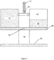
Figure 2 is a schematic representation of one example of a directional radiation detector comprising an inverse collimator. -
Figure 3 is a graph depicting the effect of a radiation field on current and voltage readings of a p-n junction silicon diode. -
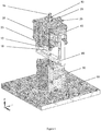
Figure 4 is an isometric schematic view of an embodiment of the present invention of a directional radiation detector comprising an inverse collimator. -
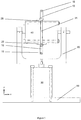
Figure 5 is a front schematic and partial cross-sectional view of the directional radiation detection apparatus shown inFigure 4 . -
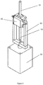
Figure 6 is an isometric schematic view of a particular embodiment of the present invention of a directional radiation detector comprising an inverse collimator. -
Figure 7 is an isometric schematic view of another example of a directional radiation detector comprising an inverse collimator, in which the inverse collimator is a diametrical spoke of a vertically oriented gear wheel. -
Figures 8A and 8B show two side views andFigure 8C shows a top view of a MATLAB display of a 3D spherical image representing a survey of the radiation sources in an environment carried out using a directional radiation detector and method employing an inverse collimator. -
Figure 9 shows a screen capture of a manual mode of directional radiation detection by a method employing inverse collimation. -
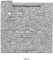
Figure 10 shows a screen capture of automatic mode user interface for directional radiation detection by a method employing inverse collimation. -
Figure 11 shows a screen capture of an extra information tab employed in a system for performing directional radiation detection using inverse collimation. -
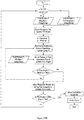
Figures 12A and12B depict a flowchart of an automatic mode of directional radiation detection by a method employing inverse collimation. - Unless defined otherwise, all technical and scientific terms used herein have the same meaning as commonly understood by one of ordinary skill in the art to which this invention belongs.
- As used in the specification and claims, the singular forms "a", "an" and "the" include plural references unless the context clearly dictates otherwise.
- The term "comprising" as used herein will be understood to mean that the list following is non-exhaustive and may or may not include any other additional suitable items, for example one or more further feature(s), component(s) and/or ingredient(s) as appropriate.
- It has now been found that an inverse collimator can be used in an improved method and apparatus for detecting both the direction and intensity of one or more sources of radiation. As detailed above, current methods and devices for detecting radiation employ a collimator, which includes a shield that blocks a radiation field incident on a radiation sensor from all directions except a narrow beam. In contrast, an inverse collimator comprises of a small radiation shield that blocks the ionizing radiation field only in a narrow beam and allows the detector to detect radiation from all other directions. Where a detector employing a collimator will generate its largest response when pointed at a source of radiation, a detector employing an inverse collimator will generate its smallest response when pointed at a source of radiation (i.e., when the radiation shield of the inverse collimator is between a radiation sensor and the source of radiation).
Figure 1 illustrates the difference in principle of operation between a detector employing a collimator, and a detector employing an inverse collimator. - Because significantly less shielding material is employed for the inverse collimator, its incorporation in a radiation detector allows the detector to be smaller, lighter, and less robustly constructed than current or previous radiation detection systems. Furthermore, the use of an inverse collimator allows the radiation detector to be remotely pointed in different directions using a relatively small and inexpensive mechanical drive.
- The inverse collimator is advantageously a rod made of lead, tungsten, or stainless steel. However, the inverse collimator can also be made of any other material capable of shielding the detector from ionizing radiation. The cross-section of the rod is optionally circular, but can have other cross-sections.
- With reference to
Figure 2 , one example of a radiation detector employsinverse collimator 10 that is a lead rod to which theradiation sensor 20 is affixed.Radiation sensor 20 shown inFigure 2 is based on a solid state diode that emits an electrical signal in response to ionizing radiation. -
Radiation sensor 20 preferably comprises a commercially available solid state p-n junction potted silicon diode used in unbiased current generation mode, and the output photocurrent is used as a measurement of the radiation field strength. While not wishing to be bound by theory, the theory behind using a diode as a radiation sensor is that diodes react to radiation the same way photodiodes react to visible light. When a diode is exposed to a radiation field, a reverse current is generated in the diode even when there is no voltage applied (i.e., unbiased mode). On a current-versus-voltage curve (IV Curve), this effect is visible as a downward shift of the curve in the presence of a radiation field (seeFigure 3 ). The relationship between this photocurrent and the radiation field strength has been studied by the inventors and found to be approximately linear. - The primary advantages of using silicon diodes as the radiation sensors in the imaging detector are that they are small, inexpensive and work for a very large range of gamma radiation dose rates.
- Having a small sensor allows the overall size of the radiation detector of the present invention to be minimized, which allows the detector to be used in confined spaces and allows it to be used in a way that causes less disruption to its surroundings. The diode is not only small, but is simple to interface with. Diodes do not have the same number of inputs and outputs of different media as are common in commercially available radiation detectors. The size and simplicity of the instrument permits great versatility in the system that uses it as a sensor.
- Various commercially available p-n junction silicon diodes have been calibrated and tested by the present inventors as radiation sensors in the directional radiation detector comprising an inverse collimator. These silicon diode sensors have been used to successfully measure radiation fields in applications in a wide range of radiation field intensities. These sensors can measure fields as low as tens of rad/hr and as high as hundreds of krad/hr (see Sur et al., "Radiation Exposure Rate and Liquid Level Inside a High Level Liquid Waste (HLLW) Storage Tank", Proceedings of the 28th Annual CNS Conference, Saint John, NB 2007 June 3-6, and see also Sur et al., "A Detector System for Measuring High Radiation Fields, paper presented at the Sixth American Nuclear Society International Topical Meeting on Nuclear Plant Instrumentation, Control, and Human-Machine Interface Technologies NPIC&HMIT, Knoxville Tennessee, April 5-9, 2009).
- Because the current output from p-n junction silicon diodes is small (on the order of pico amps to nano amps), it is preferable to use a current to voltage amplifier to amplify and convert the current signal into a voltage signal in the range of approximately 0.25 V to 8.5 V, which can be easily read with a device such as a multimeter.
- While a silicon diode-based sensor is preferred because it is relatively inexpensive and small, the sensor can also be a scintillation detector or any other type of sensor that can detect ionizing radiation and is of a size and geometry such that the
inverse collimator 10 blocks a significant portion of the radiation originating from a source located in the direction in which theinverse collimator 10 is pointing. The radiation detector of the present invention can optionally employ more than one sensor. In a further embodiment of the invention, two sensors are employed, with a sensor attached to each end of the inverse collimator. The use of a sensor on each end of the inverse collimator reduces by half the number of measurements needed to achieve a given resolution when surveying an environment for sources of radiation. - In order to permit the measurement of the intensity and direction of ionizing radiation originating from multiple sources within an environment without changing the location of the apparatus within the environment, the apparatus is advantageously equipped with pan-tilt functionality, whereby the
inverse collimator 10 can be aimed in different directions. - Preferably, the device should be able to look around itself across the entire range of directions in a sphere in steps of various sizes (depending on the resolution required) and collect radiation measurements as it is aimed in different directions. In order to achieve a resolution of 5 degrees by 5 degrees across the entire sphere, approximately 1700 steps, with measurements taken at each step, are required. For a resolution of 2 degrees by 2 degrees, approximately 10,000 steps, with measurements taken at each step, are required. In order to achieve a full sphere of range, the range of motion required is 180 degrees in tilt and 360 degrees in pan. To achieve this range of motion, two axes of rotation are required - one for pan and one for tilt.
- Again with reference to the example not forming part of the invention shown in
Figure 2 , the pan/tilt functionality is achieved by way ofmotors Pan motor 30 is affixed tobase 50 and provides the pan functionality.Tilt motor 40, is affixed toplatform 60 and provides tilt functionality. The off-centre weight ofmotor 40 is counteracted by balancingweight 70. - The
shaft 35 ofpan motor 30 is operably connected tomovable support 80. When the shaft ofmotor 30 rotates,support 80, and the other components of the apparatus located aboveplatform 80, including the inverse collimator, also rotate. - The shaft of
tilt motor 40 is operably connected to support 90, which in turn is operably connected to theinverse collimator 10. As such, when the shaft oftilt motor 40 rotates, theinverse collimator 10 also rotates. -
Figures 4 and5 show a preferred embodiment of the radiation detector of the present invention in which the motors and inverse collimator are configured such that the motor responsible for tilt functionality is incorporated in the inverse collimator geometry. The rod which comprisesinverse collimator 10 is divided into two parts located on opposite sides of the axis of rotation oftilt motor 40. Thetilt motor 40 contributes to the shielding of the detector and therefore can be considered part of the inverse collimator. The shaft of thetilt motor 40 is operably connected to movableu-shaped support 80, which in turn is operably connected to the shaft ofpan motor 30. The main advantage of this design over the embodiment shown inFigure 2 is that it avoids the need for a balancing weight, which reduces the overall weight of the apparatus. The two rods of theinverse collimator 10 are mounted to the tilt motor by means ofsupport plates 25, which are held in place bybolts 35. - The sensor (not shown) is attached to either rod of the
inverse collimator 10 at the end furthest from thetilt motor 40. The sensor is inserted throughhole 15 that is drilled perpendicular to the longitudinal axis of theinverse collimator rod 10. A threaded hole through the top of the end of theinverse collimator rod 10 parallel to its longitudinal axis (not shown) can be employed in combination with a set screw (not shown) to hold the sensor in place. In a further embodiment of the invention, two sensors can be used with a sensor inserted into the end of eachrod 10 throughhole 15. - The motors employed for pan and tilt functionality are preferably stepper motors that allow for precise position control. For example, a SureStep™ stepper motor system from Automation Direct can be employed. Such a set includes two NEMA 23 size stepper motors, two microstepping drives, and a power supply. The motors have a basic step size of 1.8° and the drives allowed microsteps of half, one-fifth, one-tenth, one-twentieth and one-fiftieth of a basic step. The power supply takes an input of 120 VAC and has outputs of 32 VDC for motor and drive power and 5 VDC for signals. Smaller NEMA 17 size motors may be employed and are considered adequate for the design shown in
Figures 4 and5 . - Another embodiment of the invention of a radiation detector that employs inverse collimation is depicted in
Figure 6 . In thisembodiment pan motor 30 is a NEMA 23 size motor andtilt motor 40 is aNEMA size 11 stepper motor (alternatively aNEMA size 8 stepper motor, or equivalent, can be used for tilt functionality). The rods of theinverse collimator 10 and the arms of theu-shaped support 80 are longer than those employed in the embodiment shown inFigures 4 and5 . The inverse collimator rod(s) include holes to accommodate the sensor or sensors (not shown inFigure 6 ). - A further example of a radiation detector that employs inverse collimation is depicted in
Figure 7 . In this example, theinverse collimator 10 is mounted in adiametrical spoke 110 of a vertically orientedgear wheel 100, captured in place and rotated for tilt bystepper motor 40 by means of adriver gear 90, which is operably connected to the shaft oftilt motor 40. This configuration provides the possibility of an inexpensive and unobtrusive tilt mechanism by manufacturing the gear wheel using a plastic "3D printer", although other means for manufacturing the gear wheel can be readily employed, and placing thetilt motor 40 out of the inverse collimator and thus not contributing to detector shielding.Gear wheel 100,driver gear 90 andtilt motor 40 are captured in place onwheel base 70, which is in turn operably connected to the shaft ofpan motor 30 to provide pan functionality. In accordance with an example not forming part of the invention, the radiation detector makes use of two NEMA 17 size stepper motors.Figure 7 shows a breakaway section view ofwheel base 70 in order to view thedriver gear 90 andtilt motor 40. Thewheel base 70 is designed to constrain thegear wheel 100 anddriver gear 90 while allowing their gears to mesh and transmit motion. The radiation detector shown inFigure 7 includes a single sensor inserted inhole 15 indiametrical spoke 110, however, an additional sensor can be incorporated ingear wheel 100 at a position approximately opposite the first sensor athole 15. - Optionally, drives with acceleration/deceleration ramping features can be employed to reduce the jerking action on the apparatus that stepper motors can impart.
- In order to obtain a map of the sources of radiation in an environment, a method can be employed whereby a radiation detector that includes an inverse collimator is used to scan the environment. To conduct a scan, the inverse collimator is pointed in various directions and the intensity of radiation incident on the sensor from each direction is recorded. A system employing such an inverse collimator generates a negative image of the sources of radiation in the environment. Mathematical image reconstruction can then be used to obtain a positive image from the scanned data. The data can be displayed three dimensionally as a pattern of colours on a spherical surface projected on a computer screen.
- Accordingly, a method of generating a radiation source map comprises (i) scanning at least part of an environment with a radiation detector that comprises a radiation sensor and an inverse collimator; and (ii) recording the intensity of radiation incident on the sensor at each position in the scan. The resulting negative image of the source(s) of radiation can be used directly to generate a radiation source map. Alternatively, as set out above, the method of generating a radiation source map further includes the step of mathematically reconstructing the negative image to generate a positive image from the recorded intensity of incident radiation.
- As would be appreciated by persons skilled in the art, the signal processing, readout, and system control functions can be implemented in individual devices or integrated into a single device, and can be implemented using hardware (e.g., a PC computer), firmware (e.g., application-specific chips), software, or combinations thereof. The computer can be a general-purpose computer that includes a computer-readable memory for storing computer program instructions for carrying out processing and control operations. The computer can also include a disk drive, a compact disk drive, USB drive or other suitable component for reading instructions contained on a computer-readable medium for carrying out such operations. In addition to output peripherals such as a display and printer, the computer can contain input peripherals such as a mouse, keyboard, barcode scanner, light pen, or other suitable component known to persons skilled in the art for enabling a user to input information into the computer.
- In one example, the radiation detector is controlled by a computer that includes a computer-readable memory that stores a computer program written specifically for the control of the radiation detector and/or for processing the data acquired using the radiation detector. In an example not forming part of the invention, the computer program is written using the LabVIEW™ platform that is designed for ease of communication with a variety of hardware. The program includes control, data acquisition, image generation and display functions. Image generation and display are achieved by recording the position and radiation data into a queue and using a MATLAB script to process the data and to display a (3D) spherical image. An example of such a display is shown in
Figures 8A-8C . The dark area on the spheres represents a Co-60 source of radiation. - The computer program is written based on the particular application of the radiation detector and makes use of standard programming platforms that are well known to workers skilled in the field.
- In accordance with an example not forming part of the invention, there can be provided a detection system that includes a computer for controlling the radiation detector. The control computer can be positioned on-site, however, it is generally located sufficiently removed from the detector to permit users to control the detector without unnecessary exposure to radiation. The control computer can include a read-write device to allow output data to be permanently, or temporarily, stored in whole or in part. The read-write device facilitates recording of the data for later consideration. The output data can be post-processed using the on-site computer, or alternatively could be conveyed to a remote computer and processed there as a result.
- The detection system can further include means for data acquisition, optionally on the control computer, and optionally in combination with means for controlling movement of the radiation detector.
- In an example not forming part of the invention, a National Instruments Data Acquisition and Control Module (NI DAQ) is used as a data acquisition and control interface between the software and the radiation detector. The NI DAQ has a number of analog and digital inputs and outputs that the program uses for all input and control purposes. The analog input is used to obtain the current measurement from the radiation sensor and the digital I/O are used to obtain feedback and to control the amplifier gain setting remotely. The motors are controlled by sending pulses to the motor drives using the +5V digital outputs on the DAQ.
- In an example not forming part of the invention, the control program has two modes of operation: manual and automatic. In both modes, all the real-time information is recorded into a computer file; this includes a timestamp, the position angles of the device (with respect to a set home position), and the sensor radiation readings including raw information such as the voltage signal and amplifier gain setting.
- The data collected by the detection system, can comprise 3-dimensional information, including the distance of the source of radiation from the detection system and its direction (or location). The 3-dimensional information can be used to reconstruct a 3-dimensional map of radiation sources (within a certain distance) in the detection area.
- In manual mode (see an example of a manual mode user interface in
Figure 9 ), the user can control the position of the device remotely while monitoring the radiation field readings. The user can pan or tilt the device in either direction in step sizes (in degrees) of his or her choosing. In addition, there is the capability to manually move the device to a desired position and set that position as the "Home Position", as well as return to the Home Position at any time. While monitoring the surroundings in manual mode, the user can take a 'snapshot' at any time. A snapshot will save all instantaneous details to a file. For example, the snapshot can save a timestamp, the position angles of the device, sensor radiation readings, and a user's comment. The sensitivity of the detector is set from the manual mode. - Automatic mode (see an example of an automatic mode user interface in
Figure 10 ) allows the user to carry out 'AutoScans', which scan the surroundings and display a radiation image. The user can control settings such as step size, dwell time (the amount of time the inverse collimator stays pointed in one direction), and whether to scan the full sphere range or only the top hemisphere. Step size is the size, in degrees, of each tilt step. The device pauses at each position, takes radiation measurements at the rate of 1 kHz and averages the measurements over the "Dwell Time", which is the amount of time the inverse collimator pauses at each position. The longer the Dwell Time, the higher the confidence in each measurement (less statistical error). It is also important to make sure that the Home Position has been set before a scan is started, because the scan starts from the Home Position. Once the proper settings are selected, the user can start an AutoScan. The software then prompts the user for a file where all the information from the AutoScan will be stored. At any time during the AutoScan process, the user can stop the scan by clicking the 'Stop Scan' button. The user can also view a partial image by clicking the 'View Image' button while the scan is running. The scanning process is paused while mathematical processing of the data takes place. The scan remains paused until the partial image is displayed. Once the scan is complete, the full image is displayed in the form of a sphere (or hemisphere) around the device. A flowchart of the steps of the automatic mode is shown inFigures 12A-12B . - Preferably, during both manual and automatic modes, additional information is provided by the LabVIEW, or equivalent, program, outside of the control program window. As shown in the example provided in
Figure 11 , this additional information can include a visual display/guide for pan and tilt angles and raw data in the form of a running waveform display of real-time current measurement from the sensor, the voltage reading from the amplifier, and the amplifier gain setting (which can be controlled automatically, or manually from the program). If the gain control is being controlled automatically, the amplifier switches its gain when the voltage output goes out of a certain range (preferably 0.25 V to 8.5 V). - As an example not forming part of the invention, the detection system can further include a visual image capturing device (e.g., a camera) for obtaining a visual image of the environment under study, such as that described in
U.S. Patent No. 7,186,963 . The visual image can be obtained prior to and/or during and/or after the radiation measurement for a particular direction or field of view within the environment. Once obtained information from one or more of the radiation measurements can be overlaid with one or more of the corresponding visual images. - All publications, patents and patent applications mentioned in this Specification are indicative of the level of skill of those skilled in the art to which this invention pertains.
- The invention being thus described, it will be obvious that the same may be varied in many ways. Such variations as would be obvious to one skilled in the art are intended to be included within the scope of the following claims.
Claims (15)
- A radiation detector for detecting both the intensity and the direction of one or more sources of radiation comprising:(a) a pan motor (30);(b) a tilt motor (40);(c) a u-shaped support (80) with a base and two arms;(d) an inverse collimator (10) comprising a first rod and a second rod; and(e) a radiation sensor (15);wherein the shaft of the pan motor is operably connected to the base of the u-shaped support such that rotation of the shaft causes rotation of the u-shaped support;
wherein the tilt motor is operably connected to the arms of the u-shaped support such that rotation of the shaft causes rotation of the tilt motor within the arms; characterised in that the first and second rods are attached to the tilt motor in longitudinal alignment with each other but on opposite sides of the axis of rotation of the tilt motor;
wherein the radiation sensor is mounted to the first rod at the end of the first rod that is farthest from the tilt motor;
wherein rotation of the pan and tilt motors allows the inverse collimator to be pointed in different directions; and
wherein the inverse collimator and tilt motor shield the sensor from at least a portion of the incident radiation originating from the direction in which the second rod is pointed. - The radiation detector of claim 1 further comprising a second radiation sensor mounted to the second rod at the end of the second rod that is farthest from the tilt motor.
- The radiation detector of claim 1 or 2 wherein the first and second rods have circular cross-sections.
- The radiation detector of any one of claims 1 to 3 wherein the first and second rods comprise a metal or metal alloy.
- The radiation detector of claim 4 wherein the metal or metal alloy is selected from the group consisting of tungsten, lead, and stainless steel.
- The radiation detector of any one of claims 1 to 5 wherein the tilt and pan motors are electric motors.
- The radiation detector of claim 6 wherein the tilt and pan motors are stepper motors.
- The radiation detector of any one of claims 1 to 7 wherein the sensor is a semiconductor diode.
- The radiation detector of claim 8 wherein the semiconductor diode is a p-n junction silicon diode.
- The radiation detector of any one of claims 1 to 9 wherein the first rod defines a first hole extending in a direction perpendicular to a longitudinal axis of the first rod, the first hole proximate the end of the first rod that is farthest from the tilt motor, and
wherein the radiation sensor is inserted in the first hole. - The radiation detector of any one of claims 1 to 9 wherein the second rod defines a second hole extending in a direction perpendicular to a longitudinal axis of the second rod, the second hole proximate the end of the second rod that is farthest from the tilt motor, and
wherein the second radiation sensor is inserted in the second hole. - The radiation detector of claim 10 wherein the first rod defines a threaded hole extending axially into the end of the first rod that is farthest from the tilt motor, the threaded hole configured to receive a screw for holding the radiation sensor in place.
- The radiation detector of claim 11 wherein the second rod defines a second threaded hole extending axially into the end of the second rod that is farthest from the tilt motor, the second threaded hole configured to receive a screw for holding the second radiation sensor in place.
- The radiation detector of any one of claims 1 to 13 further comprising a current to voltage amplifier for amplifying and converting a current signal from the radiation sensor.
- The radiation detector of any one of claims 1 to 14 wherein the pan motor and the tilt motor are configured to have a microstep size of between 0.036 and 0.9 degrees.
Applications Claiming Priority (1)
| Application Number | Priority Date | Filing Date | Title |
|---|---|---|---|
| PCT/CA2010/001618 WO2012048399A1 (en) | 2010-10-15 | 2010-10-15 | Directional radiation detection apparatus and method using inverse collimation |
Publications (3)
| Publication Number | Publication Date |
|---|---|
| EP2628021A1 EP2628021A1 (en) | 2013-08-21 |
| EP2628021A4 EP2628021A4 (en) | 2017-07-12 |
| EP2628021B1 true EP2628021B1 (en) | 2018-09-19 |
Family
ID=45830748
Family Applications (1)
| Application Number | Title | Priority Date | Filing Date |
|---|---|---|---|
| EP10858271.9A Active EP2628021B1 (en) | 2010-10-15 | 2010-10-15 | Directional radiation detection apparatus and method using inverse collimation |
Country Status (7)
| Country | Link |
|---|---|
| US (1) | US9261605B2 (en) |
| EP (1) | EP2628021B1 (en) |
| KR (2) | KR101958886B1 (en) |
| CN (1) | CN103201647B (en) |
| AR (1) | AR079576A1 (en) |
| CA (1) | CA2814242C (en) |
| WO (1) | WO2012048399A1 (en) |
Families Citing this family (17)
| Publication number | Priority date | Publication date | Assignee | Title |
|---|---|---|---|---|
| US9759823B1 (en) * | 2013-03-14 | 2017-09-12 | Los Alamos National Security, Llc | Directional radiation detectors |
| US9992917B2 (en) | 2014-03-10 | 2018-06-05 | Vulcan GMS | 3-D printing method for producing tungsten-based shielding parts |
| KR101681130B1 (en) * | 2014-07-11 | 2016-12-12 | 한국원자력연구원 | Symmetrical-type mono-sensor three-dimensional radiation detection and visualization system and method thereof |
| GB2530574B (en) * | 2014-09-29 | 2020-12-02 | Inst Jozef Stefan | Angle-sensitive gamma camera with a rotary obstruction |
| WO2016054396A1 (en) * | 2014-10-02 | 2016-04-07 | Source Production & Equipment Co., Inc. | Radiation surveying |
| KR101641524B1 (en) * | 2015-02-26 | 2016-07-22 | 한국원자력연구원 | Three-dimensional radiation detecting device with rotating sensor |
| KR101721683B1 (en) * | 2015-08-07 | 2017-03-31 | 한국원자력연구원 | Vertical-type mono-sensor three-dimensional radiation detection and visualization system and method thereof |
| FR3043211B1 (en) * | 2015-11-04 | 2019-05-17 | Commissariat A L'energie Atomique Et Aux Energies Alternatives | MEASURING DEVICE AND METHOD FOR CARTOGRAPHING AN ENVIRONMENT CARRYING OUT RADIOACTIVE SOURCES |
| JP6748461B2 (en) * | 2016-03-22 | 2020-09-02 | キヤノン株式会社 | Imprint apparatus, method of operating imprint apparatus, and article manufacturing method |
| CN106371134B (en) * | 2016-10-28 | 2023-04-07 | 湖北方圆环保科技有限公司 | Automatic sample introduction and sampling device of gamma energy spectrometer |
| FI20165923A7 (en) * | 2016-12-02 | 2018-06-03 | Environics Oy | Device, radiation detector, system and method for locating a radiation source |
| US10054697B1 (en) * | 2017-04-11 | 2018-08-21 | Consolidated Nuclear Security, LLC | Device and method for locating a radiation emitting source via angular dependence using a single detection crystal |
| CN108181606A (en) * | 2017-12-28 | 2018-06-19 | 成都信息工程大学 | Radiation source based on array element radiation energy is made an uproar passive orientation method |
| CN109490338B (en) * | 2018-12-19 | 2024-03-26 | 许昌瑞示电子科技有限公司 | Radiation imaging system and its equipment compartment and radiation source installation components |
| CN110018509A (en) * | 2019-03-05 | 2019-07-16 | 中国辐射防护研究院 | It is a kind of for looking for the scanning visualization device of gamma source item hot spot in space |
| CA3135657A1 (en) | 2019-04-04 | 2020-10-08 | Atomic Energy Of Canada Limited / Energie Atomique Du Canada Limitee | Radiation detection device with directional radiation detector |
| CN115032680B (en) * | 2022-05-12 | 2024-09-27 | 中国原子能科学研究院 | Positioning device and source-seeking equipment |
Family Cites Families (11)
| Publication number | Priority date | Publication date | Assignee | Title |
|---|---|---|---|---|
| US5286973A (en) * | 1991-11-13 | 1994-02-15 | Odetics, Inc. | Radiation mapping system |
| GB9922754D0 (en) * | 1999-09-27 | 1999-11-24 | British Nuclear Fuels Plc | Improvements in and relating to methods and apparatus for investigating emissions |
| SE0000957D0 (en) * | 2000-02-08 | 2000-03-21 | Digiray Ab | Detector and method for detection of ionizing radiation |
| GB0128361D0 (en) | 2001-11-27 | 2002-01-16 | British Nuclear Fuels Plc | Improvements in and relating to instruments |
| FI112285B (en) * | 2001-12-20 | 2003-11-14 | Ari Virtanen | Method and apparatus for determining the intensity distribution of a time-dependent radiation field |
| JP4184701B2 (en) * | 2002-04-19 | 2008-11-19 | エスアイアイ・ナノテクノロジー株式会社 | Radiation detector |
| TW200404515A (en) * | 2002-08-21 | 2004-04-01 | Hamamatsu Photonics Kk | Radiation detector |
| US7242003B2 (en) * | 2004-09-24 | 2007-07-10 | Siemens Medical Solutions Usa, Inc. | Inverse collimation for nuclear medicine imaging |
| US7335888B2 (en) * | 2004-09-24 | 2008-02-26 | Siemens Medical Solutions Usa, Inc. | Imaging apparatus to acquire tomography projections with improved orbit |
| US20070223651A1 (en) * | 2006-03-21 | 2007-09-27 | Wagenaar Douglas J | Dual modality mammography device |
| KR100806072B1 (en) * | 2006-04-10 | 2008-02-21 | 한국원자력연구원 | Radiation source 3D position detection method and apparatus using two CD cameras |
-
2010
- 2010-10-15 KR KR1020177035388A patent/KR101958886B1/en active Active
- 2010-10-15 WO PCT/CA2010/001618 patent/WO2012048399A1/en not_active Ceased
- 2010-10-15 CA CA2814242A patent/CA2814242C/en active Active
- 2010-10-15 EP EP10858271.9A patent/EP2628021B1/en active Active
- 2010-10-15 US US13/878,719 patent/US9261605B2/en active Active
- 2010-10-15 KR KR1020137009570A patent/KR20130121828A/en not_active Ceased
- 2010-10-15 CN CN201080069625.3A patent/CN103201647B/en active Active
- 2010-12-21 AR ARP100104804A patent/AR079576A1/en active IP Right Grant
Non-Patent Citations (1)
| Title |
|---|
| None * |
Also Published As
| Publication number | Publication date |
|---|---|
| US20130206995A1 (en) | 2013-08-15 |
| EP2628021A4 (en) | 2017-07-12 |
| CN103201647A (en) | 2013-07-10 |
| EP2628021A1 (en) | 2013-08-21 |
| CN103201647B (en) | 2016-08-03 |
| WO2012048399A1 (en) | 2012-04-19 |
| CA2814242C (en) | 2020-01-07 |
| KR101958886B1 (en) | 2019-03-15 |
| KR20170141262A (en) | 2017-12-22 |
| KR20130121828A (en) | 2013-11-06 |
| AR079576A1 (en) | 2012-02-01 |
| CA2814242A1 (en) | 2012-04-19 |
| US9261605B2 (en) | 2016-02-16 |
Similar Documents
| Publication | Publication Date | Title |
|---|---|---|
| CA2814242C (en) | Directional radiation detection apparatus and method using inverse collimation | |
| JP5918093B2 (en) | Radiation measurement apparatus and radiation measurement method | |
| Gmar et al. | Development of coded-aperture imaging with a compact gamma camera | |
| Tsitsimpelis et al. | Simultaneous, robot-compatible γ-ray spectroscopy and imaging of an operating nuclear reactor | |
| US11047997B2 (en) | Rotating scatter mask for directional radiation detection and imaging | |
| Andersson et al. | Neutron tomography of axially symmetric objects using 14 MeV neutrons from a portable neutron generator | |
| Sinha et al. | A novel method for NDT applications using NXCT system at the Missouri University of Science & Technology | |
| Redus et al. | An imaging nuclear survey system | |
| GB2293742A (en) | Gamma ray imaging | |
| Matoušková et al. | New detector design of STORNI neutron imaging facility at RA-6 research reactor | |
| Sato et al. | Three-dimensional visualization of a beta-emitting nuclide by combining a directional Geiger-Mueller counter and structure from motion | |
| Lévai et al. | Use of high energy gamma emission tomography for partial defect verification of spent fuel assemblies | |
| Lunardini | Testing neutrino spectra formation in collapsing stars with the diffuse supernova neutrino flux | |
| Ivanov et al. | A Gamma Scanner with an Anticollimator for Visualization of γ-Radiation Sources | |
| Aspinall et al. | Real-time capabilities of a digital analyzer for mixed-field assay using scintillation detectors | |
| CN114366135B (en) | PET detector monitoring method, device, storage medium and electronic equipment | |
| Chesnokov et al. | Surface activity distribution measurements and establishment of a dose rate map inside the destroyed Chernobyl reactor | |
| CN220568943U (en) | Corrosion product in-situ gamma spectroscopy measurement device | |
| Sinclair et al. | Gamma Imagers for Nuclear Security and Nuclear Forensics: Recommendations based on results from a side-by-side intercomparison | |
| KR20120122322A (en) | Distribution of radiation measurement devices Image | |
| Joung et al. | Evaluation of a new gamma emission imaging system and method for nuclear waste in nuclear power plant environments | |
| Brodish | A scattering of experiments: neutron radiography for non-destructive characterization of materials in nuclear science, engineering, manufacturing, and natural heritage | |
| Wicaksono et al. | DEVELOPMENT OF THE EXPERIMENTAL MODULES BASED ON A RADIATION DETECTION SYSTEM IN INTERNET REACTOR LABORATORY USING THE KARTINI REACTOR | |
| Chen-Mayer et al. | Instrumentation for Activation Analysis | |
| Stepanov et al. | Remote-Controlled Collimated System Gamma Locator for Remote Measurements of Radioactivity Distribution–10388 |
Legal Events
| Date | Code | Title | Description |
|---|---|---|---|
| PUAI | Public reference made under article 153(3) epc to a published international application that has entered the european phase |
Free format text: ORIGINAL CODE: 0009012 |
|
| 17P | Request for examination filed |
Effective date: 20130510 |
|
| AK | Designated contracting states |
Kind code of ref document: A1 Designated state(s): AL AT BE BG CH CY CZ DE DK EE ES FI FR GB GR HR HU IE IS IT LI LT LU LV MC MK MT NL NO PL PT RO RS SE SI SK SM TR |
|
| DAX | Request for extension of the european patent (deleted) | ||
| RA4 | Supplementary search report drawn up and despatched (corrected) |
Effective date: 20170614 |
|
| RIC1 | Information provided on ipc code assigned before grant |
Ipc: G01T 1/169 20060101AFI20170608BHEP Ipc: G01T 7/00 20060101ALI20170608BHEP Ipc: G01T 1/24 20060101ALI20170608BHEP |
|
| GRAP | Despatch of communication of intention to grant a patent |
Free format text: ORIGINAL CODE: EPIDOSNIGR1 |
|
| INTG | Intention to grant announced |
Effective date: 20180404 |
|
| GRAS | Grant fee paid |
Free format text: ORIGINAL CODE: EPIDOSNIGR3 |
|
| GRAA | (expected) grant |
Free format text: ORIGINAL CODE: 0009210 |
|
| AK | Designated contracting states |
Kind code of ref document: B1 Designated state(s): AL AT BE BG CH CY CZ DE DK EE ES FI FR GB GR HR HU IE IS IT LI LT LU LV MC MK MT NL NO PL PT RO RS SE SI SK SM TR |
|
| REG | Reference to a national code |
Ref country code: GB Ref legal event code: FG4D |
|
| REG | Reference to a national code |
Ref country code: CH Ref legal event code: EP |
|
| REG | Reference to a national code |
Ref country code: AT Ref legal event code: REF Ref document number: 1043894 Country of ref document: AT Kind code of ref document: T Effective date: 20181015 |
|
| REG | Reference to a national code |
Ref country code: IE Ref legal event code: FG4D |
|
| REG | Reference to a national code |
Ref country code: DE Ref legal event code: R096 Ref document number: 602010053791 Country of ref document: DE |
|
| REG | Reference to a national code |
Ref country code: FR Ref legal event code: PLFP Year of fee payment: 9 |
|
| REG | Reference to a national code |
Ref country code: RO Ref legal event code: EPE |
|
| REG | Reference to a national code |
Ref country code: NL Ref legal event code: MP Effective date: 20180919 |
|
| PG25 | Lapsed in a contracting state [announced via postgrant information from national office to epo] |
Ref country code: GR Free format text: LAPSE BECAUSE OF FAILURE TO SUBMIT A TRANSLATION OF THE DESCRIPTION OR TO PAY THE FEE WITHIN THE PRESCRIBED TIME-LIMIT Effective date: 20181220 Ref country code: LT Free format text: LAPSE BECAUSE OF FAILURE TO SUBMIT A TRANSLATION OF THE DESCRIPTION OR TO PAY THE FEE WITHIN THE PRESCRIBED TIME-LIMIT Effective date: 20180919 Ref country code: BG Free format text: LAPSE BECAUSE OF FAILURE TO SUBMIT A TRANSLATION OF THE DESCRIPTION OR TO PAY THE FEE WITHIN THE PRESCRIBED TIME-LIMIT Effective date: 20181219 Ref country code: SE Free format text: LAPSE BECAUSE OF FAILURE TO SUBMIT A TRANSLATION OF THE DESCRIPTION OR TO PAY THE FEE WITHIN THE PRESCRIBED TIME-LIMIT Effective date: 20180919 Ref country code: NO Free format text: LAPSE BECAUSE OF FAILURE TO SUBMIT A TRANSLATION OF THE DESCRIPTION OR TO PAY THE FEE WITHIN THE PRESCRIBED TIME-LIMIT Effective date: 20181219 Ref country code: FI Free format text: LAPSE BECAUSE OF FAILURE TO SUBMIT A TRANSLATION OF THE DESCRIPTION OR TO PAY THE FEE WITHIN THE PRESCRIBED TIME-LIMIT Effective date: 20180919 Ref country code: RS Free format text: LAPSE BECAUSE OF FAILURE TO SUBMIT A TRANSLATION OF THE DESCRIPTION OR TO PAY THE FEE WITHIN THE PRESCRIBED TIME-LIMIT Effective date: 20180919 |
|
| REG | Reference to a national code |
Ref country code: LT Ref legal event code: MG4D |
|
| PG25 | Lapsed in a contracting state [announced via postgrant information from national office to epo] |
Ref country code: HR Free format text: LAPSE BECAUSE OF FAILURE TO SUBMIT A TRANSLATION OF THE DESCRIPTION OR TO PAY THE FEE WITHIN THE PRESCRIBED TIME-LIMIT Effective date: 20180919 Ref country code: LV Free format text: LAPSE BECAUSE OF FAILURE TO SUBMIT A TRANSLATION OF THE DESCRIPTION OR TO PAY THE FEE WITHIN THE PRESCRIBED TIME-LIMIT Effective date: 20180919 Ref country code: AL Free format text: LAPSE BECAUSE OF FAILURE TO SUBMIT A TRANSLATION OF THE DESCRIPTION OR TO PAY THE FEE WITHIN THE PRESCRIBED TIME-LIMIT Effective date: 20180919 |
|
| REG | Reference to a national code |
Ref country code: AT Ref legal event code: MK05 Ref document number: 1043894 Country of ref document: AT Kind code of ref document: T Effective date: 20180919 |
|
| PG25 | Lapsed in a contracting state [announced via postgrant information from national office to epo] |
Ref country code: ES Free format text: LAPSE BECAUSE OF FAILURE TO SUBMIT A TRANSLATION OF THE DESCRIPTION OR TO PAY THE FEE WITHIN THE PRESCRIBED TIME-LIMIT Effective date: 20180919 Ref country code: NL Free format text: LAPSE BECAUSE OF FAILURE TO SUBMIT A TRANSLATION OF THE DESCRIPTION OR TO PAY THE FEE WITHIN THE PRESCRIBED TIME-LIMIT Effective date: 20180919 Ref country code: AT Free format text: LAPSE BECAUSE OF FAILURE TO SUBMIT A TRANSLATION OF THE DESCRIPTION OR TO PAY THE FEE WITHIN THE PRESCRIBED TIME-LIMIT Effective date: 20180919 Ref country code: EE Free format text: LAPSE BECAUSE OF FAILURE TO SUBMIT A TRANSLATION OF THE DESCRIPTION OR TO PAY THE FEE WITHIN THE PRESCRIBED TIME-LIMIT Effective date: 20180919 Ref country code: IT Free format text: LAPSE BECAUSE OF FAILURE TO SUBMIT A TRANSLATION OF THE DESCRIPTION OR TO PAY THE FEE WITHIN THE PRESCRIBED TIME-LIMIT Effective date: 20180919 Ref country code: CZ Free format text: LAPSE BECAUSE OF FAILURE TO SUBMIT A TRANSLATION OF THE DESCRIPTION OR TO PAY THE FEE WITHIN THE PRESCRIBED TIME-LIMIT Effective date: 20180919 Ref country code: IS Free format text: LAPSE BECAUSE OF FAILURE TO SUBMIT A TRANSLATION OF THE DESCRIPTION OR TO PAY THE FEE WITHIN THE PRESCRIBED TIME-LIMIT Effective date: 20190119 Ref country code: PL Free format text: LAPSE BECAUSE OF FAILURE TO SUBMIT A TRANSLATION OF THE DESCRIPTION OR TO PAY THE FEE WITHIN THE PRESCRIBED TIME-LIMIT Effective date: 20180919 |
|
| PG25 | Lapsed in a contracting state [announced via postgrant information from national office to epo] |
Ref country code: PT Free format text: LAPSE BECAUSE OF FAILURE TO SUBMIT A TRANSLATION OF THE DESCRIPTION OR TO PAY THE FEE WITHIN THE PRESCRIBED TIME-LIMIT Effective date: 20190119 Ref country code: SK Free format text: LAPSE BECAUSE OF FAILURE TO SUBMIT A TRANSLATION OF THE DESCRIPTION OR TO PAY THE FEE WITHIN THE PRESCRIBED TIME-LIMIT Effective date: 20180919 Ref country code: SM Free format text: LAPSE BECAUSE OF FAILURE TO SUBMIT A TRANSLATION OF THE DESCRIPTION OR TO PAY THE FEE WITHIN THE PRESCRIBED TIME-LIMIT Effective date: 20180919 |
|
| REG | Reference to a national code |
Ref country code: CH Ref legal event code: PL |
|
| REG | Reference to a national code |
Ref country code: DE Ref legal event code: R097 Ref document number: 602010053791 Country of ref document: DE |
|
| REG | Reference to a national code |
Ref country code: BE Ref legal event code: MM Effective date: 20181031 |
|
| PG25 | Lapsed in a contracting state [announced via postgrant information from national office to epo] |
Ref country code: LU Free format text: LAPSE BECAUSE OF NON-PAYMENT OF DUE FEES Effective date: 20181015 |
|
| REG | Reference to a national code |
Ref country code: DE Ref legal event code: R082 Ref document number: 602010053791 Country of ref document: DE Representative=s name: MEISSNER BOLTE PATENTANWAELTE RECHTSANWAELTE P, DE |
|
| REG | Reference to a national code |
Ref country code: IE Ref legal event code: MM4A |
|
| PLBE | No opposition filed within time limit |
Free format text: ORIGINAL CODE: 0009261 |
|
| STAA | Information on the status of an ep patent application or granted ep patent |
Free format text: STATUS: NO OPPOSITION FILED WITHIN TIME LIMIT |
|
| PG25 | Lapsed in a contracting state [announced via postgrant information from national office to epo] |
Ref country code: MC Free format text: LAPSE BECAUSE OF FAILURE TO SUBMIT A TRANSLATION OF THE DESCRIPTION OR TO PAY THE FEE WITHIN THE PRESCRIBED TIME-LIMIT Effective date: 20180919 Ref country code: DK Free format text: LAPSE BECAUSE OF FAILURE TO SUBMIT A TRANSLATION OF THE DESCRIPTION OR TO PAY THE FEE WITHIN THE PRESCRIBED TIME-LIMIT Effective date: 20180919 |
|
| 26N | No opposition filed |
Effective date: 20190620 |
|
| PG25 | Lapsed in a contracting state [announced via postgrant information from national office to epo] |
Ref country code: BE Free format text: LAPSE BECAUSE OF NON-PAYMENT OF DUE FEES Effective date: 20181031 Ref country code: CH Free format text: LAPSE BECAUSE OF NON-PAYMENT OF DUE FEES Effective date: 20181031 Ref country code: LI Free format text: LAPSE BECAUSE OF NON-PAYMENT OF DUE FEES Effective date: 20181031 |
|
| PG25 | Lapsed in a contracting state [announced via postgrant information from national office to epo] |
Ref country code: IE Free format text: LAPSE BECAUSE OF NON-PAYMENT OF DUE FEES Effective date: 20181015 Ref country code: SI Free format text: LAPSE BECAUSE OF FAILURE TO SUBMIT A TRANSLATION OF THE DESCRIPTION OR TO PAY THE FEE WITHIN THE PRESCRIBED TIME-LIMIT Effective date: 20180919 |
|
| PG25 | Lapsed in a contracting state [announced via postgrant information from national office to epo] |
Ref country code: MT Free format text: LAPSE BECAUSE OF NON-PAYMENT OF DUE FEES Effective date: 20181015 |
|
| PG25 | Lapsed in a contracting state [announced via postgrant information from national office to epo] |
Ref country code: TR Free format text: LAPSE BECAUSE OF FAILURE TO SUBMIT A TRANSLATION OF THE DESCRIPTION OR TO PAY THE FEE WITHIN THE PRESCRIBED TIME-LIMIT Effective date: 20180919 |
|
| PG25 | Lapsed in a contracting state [announced via postgrant information from national office to epo] |
Ref country code: MK Free format text: LAPSE BECAUSE OF NON-PAYMENT OF DUE FEES Effective date: 20180919 Ref country code: HU Free format text: LAPSE BECAUSE OF FAILURE TO SUBMIT A TRANSLATION OF THE DESCRIPTION OR TO PAY THE FEE WITHIN THE PRESCRIBED TIME-LIMIT; INVALID AB INITIO Effective date: 20101015 Ref country code: CY Free format text: LAPSE BECAUSE OF FAILURE TO SUBMIT A TRANSLATION OF THE DESCRIPTION OR TO PAY THE FEE WITHIN THE PRESCRIBED TIME-LIMIT Effective date: 20180919 |
|
| PGFP | Annual fee paid to national office [announced via postgrant information from national office to epo] |
Ref country code: GB Payment date: 20250918 Year of fee payment: 16 |
|
| PGFP | Annual fee paid to national office [announced via postgrant information from national office to epo] |
Ref country code: FR Payment date: 20250922 Year of fee payment: 16 |
|
| PGFP | Annual fee paid to national office [announced via postgrant information from national office to epo] |
Ref country code: DE Payment date: 20250916 Year of fee payment: 16 |
|
| PGFP | Annual fee paid to national office [announced via postgrant information from national office to epo] |
Ref country code: RO Payment date: 20251008 Year of fee payment: 16 |