EP2627840B1 - Fence - Google Patents
Fence Download PDFInfo
- Publication number
- EP2627840B1 EP2627840B1 EP11770056.7A EP11770056A EP2627840B1 EP 2627840 B1 EP2627840 B1 EP 2627840B1 EP 11770056 A EP11770056 A EP 11770056A EP 2627840 B1 EP2627840 B1 EP 2627840B1
- Authority
- EP
- European Patent Office
- Prior art keywords
- fence
- flange
- wire
- click
- panel
- Prior art date
- Legal status (The legal status is an assumption and is not a legal conclusion. Google has not performed a legal analysis and makes no representation as to the accuracy of the status listed.)
- Not-in-force
Links
Images



Classifications
-
- E—FIXED CONSTRUCTIONS
- E04—BUILDING
- E04H—BUILDINGS OR LIKE STRUCTURES FOR PARTICULAR PURPOSES; SWIMMING OR SPLASH BATHS OR POOLS; MASTS; FENCING; TENTS OR CANOPIES, IN GENERAL
- E04H17/00—Fencing, e.g. fences, enclosures, corrals
- E04H17/14—Fences constructed of rigid elements, e.g. with additional wire fillings or with posts
- E04H17/16—Fences constructed of rigid elements, e.g. with additional wire fillings or with posts using prefabricated panel-like elements, e.g. wired frames
- E04H17/161—Fences constructed of rigid elements, e.g. with additional wire fillings or with posts using prefabricated panel-like elements, e.g. wired frames using wire panels
Definitions
- the present invention relates to a fence comprising at least one fence panel which is in the form of a wire panel comprising horizontal wires which, in the installed position of the fence, extend substantially horizontally and vertical wires which, in the installed position of the fence, extend substantially vertically and comprising at least one fence post which comprises at least one upright hook element over which at least one horizontal wire can be hooked in order to hold said horizontal wire for attaching the fence panel to the fence post.
- wire panels are often attached to fence posts. This usually involves the use of clamping rings, brackets, adapted clamping pieces etc., with a wire panel being clamped between these clamping rings, brackets, clamping pieces, etc. and the fence post, thus necessitating the use of screwdrivers or other accessories when fitting the fence.
- a plurality of fence posts have already been developed which do not require the use of such accessories in order to attach wire panels to fence posts.
- fences have been developed in which wire panels are attached to the fence posts using a hook system, where a vertical or a horizontal wire of a wire panel is in each case hooked to a fence post.
- a drawback of fences in which the vertical wire is attached is that the fence post comprises folded-over parts behind which the vertical wire is hooked and which are difficult to coat evenly.
- the present invention relates to such fences in which the horizontal wire is hooked to a fence post.
- this makes it possible to attach fence panels to fence posts less securely and still allows for the simple detachment thereof. Therefore, an additional fastening means will often also be used in practice, such as that used with the fence from FR 2 923 248 A1 (or the respective patent application EP 2 055 866 A1 ) to complement such a hook system in order to attach the fence panels more securely to the fence posts and/or to render detachment more difficult or to prevent it.
- the fence from FR 2 890 407 A3 no separate fastening means are used, but instead lips on the fence post are folded over with a specially developed hand tool after fitting of the panel.
- a fence comprising at least one fence panel in the form of a wire panel, comprising horizontal wires which, in the installed position of the fence, extend substantially horizontally and vertical wires which, in the installed position of the fence, extend substantially vertically and comprising at least one fence post, in which this fence post comprises at least one upright hook element onto which at least one horizontal wire can be hooked in order to hold this horizontal wire for attaching the fence panel to the fence post and in which this fence post comprises at least one detaining element which is integrally formed with this fence post in the form of a click element in order to click-fit a horizontal wire onto the hook element when the former is hooked into the hook element, for detaining the wire panel when an attempt is made to lift the wire panel from the installed position of the fence out of engagement with the hook element.
- this fence post comprises at least one detaining element which is integrally formed with this fence post in the form of a click element in order to click-fit a horizontal wire onto the hook element when the former is hooked into the hook element, for det
- the fence post of a fence according to the invention with detaining element can comprise at least one flange and the hook element forms part of this flange and this hook element is formed by a slot which is provided at the end of this flange.
- this click element can then be formed by partly punching out a part of the flange at the location of the hook element and folding it over.
- this click element can be formed by folding out a part of the flange at the location of the hook element.
- this click element can alternatively also form part of the flange and be formed by providing a local constriction in the slot.
- a significant advantage of such an embodiment is that both the hook elements and the click elements can be formed together in a single process step during production.
- a fence according to the present invention may furthermore comprise a reinforcing pillar and a web plate connected thereto, with the flange being provided at the end of the web plate.
- the flange is then preferably a folded-over flange, comprising a first part which extends virtually at right angles to the web plate and a second part which is directed substantially towards the reinforcing pillar.
- the additional advantage of constructing a fence post in this way is that it can be formed in such a way that all parts of the flange remain readily accessible for the purpose of applying a protective coating, thereby significantly increasing the service life of the fence post compared to fence posts comprising click elements according to the prior art.
- fence posts according to the prior art in which a vertical wire of a fence can be click-fitted to this fence post, not all locations are readily accessible in order to be able to apply a protective coating.
- the slot in the flange is preferably provided in the second part of the flange.
- a click element as detaining element which is formed by either partly punching out and folding over a part of the flange, or by folding a part of the flange
- this click element is preferably provided in the first part of the flange.
- a slot and a click element are in this case provided at the location of one another.
- the fence post comprises two flanges, each of which is provided with slots in order to form hook elements so as to hook horizontal wires of fence panels thereon.
- the fence post is preferably of virtually symmetrical design.
- a fence (1) according to the present invention as is illustrated in Fig. 1 and Fig. 5 , comprises one or more fence posts (2) and one or more fence panels (3). Parts of this fence (1) are illustrated in more detail in the other figures.
- the fence panels (3) are wire panels and comprise horizontal wires (3a) and vertical wires (3b) which have been welded to one another at the spots where they cross. These wires (3a, 3b) are preferably made from galvanised steel.
- the illustrated fence posts (2) are posts which have been folded from sheet metal.
- this sheet metal is galvanized steel.
- These fence posts (2) comprise a reinforcing pillar (7), a web plate (8) connected thereto and two folded-over flanges (9a, 9b).
- the folded-over flanges (9a, 9b) each comprise a first part (9a) which extends virtually at right angles to the web plate (8) and a second part (9b) which is directed substantially towards the reinforcing pillar (7).
- the illustrated fence posts (2) are of a symmetrical design, so that two fence panels (3) can be attached to this fence post (2) in such a manner that they are in line with one another.
- the second parts (9b) of the flanges (9a, 9b) are in each case provided with downwardly directed slots (6) which end at the end of the flanges (9a, 9b) and into which a horizontal wire (3a) of a wire panel (3) can be fitted.
- These slots (6) delimit upright hook elements (4), onto which the horizontal wire (3a) can be hooked.
- parts (5) of the flange (9a, 9b) are partly punched out and folded in the first parts (9a) of the flanges (9a, 9b) at the location of the slots (6), as can best be seen in Fig. 4 .
- These parts (5) form click elements (5) acting as detaining elements (5), by means of which the horizontal wire (3a) can be click-fitted in order to retain it in the respective hook element (4).
- click elements (5) are punched out of the sheet metal and folded in such a way that they can be elastically deformed. They delimit a passage in the respective hook element (4) which is narrower than the diameter of a horizontal wire (3a).
- the slot (6) has a width which is greater than or equal to the diameter of the horizontal wire (3a).
- a horizontal wire (3a) When a horizontal wire (3a) is hooked over a hook element (4), it can be pulled through the passage in this manner, in which case the click element (5) temporarily deforms elastically.
- the horizontal wire (3) can be pulled through this passage by using the force of gravity, optionally with the use of a small additional force.
- this horizontal wire (3a) can be click-fitted into the hook element (4) by means of the respective click element (5).
- this click element (5) forms an impediment when the fence panels (3) have to be detached. If a fence panel (3) in this installed position has to be lifted out of the hook element (4), the horizontal wire (3a) fitted in the hook element (4) hits this click element (5) which serves as a detaining element (5). Due to the design of the punched-out and folded-over parts as detaining elements (5), they deform elastically when the horizontal wire (3a) is hooked into the hook element (4), as a result of which this horizontal wire (3 a) can easily be click-fitted. However, when trying to remove the wire panel (3), this detaining element (5) prevents this horizontal wire (3a) from being lifted out of engagement.
- all slots (6) are provided with a constriction (11) which in each case forms a click element (5) in the flange (9a, 9b), as can best be seen in Fig. 7 .
- These constrictions (11) form click elements (5) acting as first detaining elements (5) for this embodiment, by means of which the horizontal wire (3a) can be click-fitted in order to retain it in the respective hook element (4).
- the constrictions (11) in the illustrated embodiment are in each case provided at the end of the hook elements (4). These ends of the hook elements (4) can deform elastically.
- Each constriction (11) is narrower than the diameter of a horizontal wire (3a).
- the remainder of the respective slot (6) has a width which is greater than or equal to the diameter of the horizontal wire (3a).
- a horizontal wire (3a) When a horizontal wire (3a) is hooked over a hook element (4), it can be pulled through the constriction (11) in this manner, in which case the end of the respective hook element (4) temporarily deforms elastically.
- the horizontal wire (3) can be pulled through this constriction (11) by using the force of gravity, optionally with the use of a small additional force.
- this horizontal wire (3a) can be click-fitted into the hook element (4) by means of the respective click element (5).
- the fence posts (2) of the embodiment from Figs. 5 to 18 at the ends of the second parts (9b) of the flanges (9a, 9b), in each case just above the slots (6), are provided with a lip (10) which is turned towards the web plate (8).
- This lip (10) serves as a second detaining element (10).
- this lip (10) forms an additional obstacle when trying to detach the fence panels (3).
- the horizontal wire (3a) which is arranged in the hook element (4) hits the click element (5), as can clearly be seen in Fig. 17 .
- this first detaining element (5) can only detain the wire panel (3) when small forces are applied when it is being lifted out of engagement.
- the bent-over part of a vertical wire (3b) which forms part of the nose (12) hits the lip (10) in the form of a second detaining element (10) when the fence panel (3) is being lifted out of engagement.
- This lip (10) is a rigid detaining element (10) which therefore also detains the wire panel (3) when relatively large forces are being used during its removal.
- An embodiment of a fence (1) according to the present invention which is not illustrated comprises only said lips (10) as detaining elements and no click elements (5).
- the illustrated fence posts (2) are made from sheet metal by folding and can be produced in a simple manner. After folding, they can furthermore be provided with a protective coating. Due to the design of the fence posts (2) in which the second parts (9b) of the flanges (9a, 9b) are turned towards the reinforcing pillar (7), all parts of these fence posts (2) are readily accessible so as to be able to apply this coating.
- fence posts (2) could equally well be made out of other materials and/or be produced using other production methods.
- Such a fence post (2) according to the invention could, for example, also comprise a beam-shaped or round post to which upright hook elements (4) are attached and which is furthermore, for example, provided with click elements (5) acting as detaining elements for click-fitting a horizontal wire (3a) to such a hook element (4).
- the illustrated wire panels (3) are three-dimensional wire panels (3) which are provided with noses (12) which are formed by horizontal wires (3a) extending beyond the plane in which most wires (3a, 3b) of the wire panel (3) essentially extend.
- the passage between the reinforcing pillar (7) and the second part (9b) of the flange (9a, 9b) has a width which corresponds to the width of the wire panel (3) and, more specifically, to the width of these noses (12), so that the end of this wire panel (3) can be fitted through this passage.
- this wire panel (3) is first positioned next to this fence post (2), as is illustrated in Figs. 9 and 10 . Thereafter, the end of the fence panel (2), viewed in the plane view from Fig. 10 , is pushed to the left, between said passage between the reinforcing pillar (7) and the second part (9b) of the flange (9a, 9b), until this wire panel (3) is situated virtually against the web plate (8), as is illustrated in Figs. 11 and 12 .
- the horizontal wires (3a) of the fence panel (3) which adjoin the second part (9b) of the flange (9a, 9b) are positioned at the location of the entrances of the slots (6) in this second part (9b), as can clearly be seen in Fig. 11 .
- the wire panel (3) is moved to the first part (9a) of the flange (9a, 9b) until this wire panel (3) comes to lie virtually against this first part (9a).
- the horizontal wires (3a) which were positioned in front of the entrances of the slots (6) are in this case fitted in these slots (6).
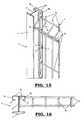
- this wire panel (3) is then pulled downwards, in which case said horizontal wires (3a) are pulled through the constrictions in the respective slots (6), as can clearly be seen in Figs. 15 and 16 .
- the wire panel (3) viewed in the plan view of Fig. 16 , is again moved to the right-hand side, until the vertical wire (3b) which is situated in the cavity between the flange (9a, 9b) and the web plate (8) is pulled up against the second part (9b) of the flange (9a, 9b), as can clearly be seen in Fig. 18 .
Landscapes
- Engineering & Computer Science (AREA)
- Architecture (AREA)
- Civil Engineering (AREA)
- Structural Engineering (AREA)
- Fencing (AREA)
Description
- The present invention relates to a fence comprising at least one fence panel which is in the form of a wire panel comprising horizontal wires which, in the installed position of the fence, extend substantially horizontally and vertical wires which, in the installed position of the fence, extend substantially vertically and comprising at least one fence post which comprises at least one upright hook element over which at least one horizontal wire can be hooked in order to hold said horizontal wire for attaching the fence panel to the fence post.
- In order to create fences, wire panels are often attached to fence posts. This usually involves the use of clamping rings, brackets, adapted clamping pieces etc., with a wire panel being clamped between these clamping rings, brackets, clamping pieces, etc. and the fence post, thus necessitating the use of screwdrivers or other accessories when fitting the fence.
- A plurality of fence posts have already been developed which do not require the use of such accessories in order to attach wire panels to fence posts.
- Thus, fences have been developed in which wire panels are attached to the fence posts using a hook system, where a vertical or a horizontal wire of a wire panel is in each case hooked to a fence post.
- A drawback of fences in which the vertical wire is attached, such as for example the fence from
EP 1 306 502 A1 - The present invention relates to such fences in which the horizontal wire is hooked to a fence post. However, this makes it possible to attach fence panels to fence posts less securely and still allows for the simple detachment thereof. Therefore, an additional fastening means will often also be used in practice, such as that used with the fence from
FR 2 923 248 A1patent application EP 2 055 866 A1 ) to complement such a hook system in order to attach the fence panels more securely to the fence posts and/or to render detachment more difficult or to prevent it. With the fence fromFR 2 890 407 A3BE 1 017 701 A3claim 1, downwardly directed hooks are hooked over horizontal wires in order to prevent detachment of the fence panels. In the fence as described inEP-A-2055866 , which also comprises all of the features of the preamble ofclaim 1, the fence panels are secured by additional stirrup-shaped locking elements. - It is an object of the present invention to provide an alternative to such a fence with a hook system in which a horizontal wire of a wire panel is hooked to a fence panel, in which the post can be evenly coated in a simple manner and in which no additional accessories such as fastening means or hand tools are required in order to prevent the fence from being taken down.
- This object of the invention is achieved by providing a fence comprising at least one fence panel in the form of a wire panel, comprising horizontal wires which, in the installed position of the fence, extend substantially horizontally and vertical wires which, in the installed position of the fence, extend substantially vertically and comprising at least one fence post, in which this fence post comprises at least one upright hook element onto which at least one horizontal wire can be hooked in order to hold this horizontal wire for attaching the fence panel to the fence post and in which this fence post comprises at least one detaining element which is integrally formed with this fence post in the form of a click element in order to click-fit a horizontal wire onto the hook element when the former is hooked into the hook element, for detaining the wire panel when an attempt is made to lift the wire panel from the installed position of the fence out of engagement with the hook element. In addition, it is readily possible to configure such a detaining element in such a manner that the fence post can be coated evenly.
- If such a detaining element prevents the wire panel from being lifted out of engagement with an upright hook element after a horizontal wire has been hooked thereto, taking down of the fence is rendered more difficult while no additional accessories are required to achieve this.
- Fences have already been developed in the prior art in which a vertical wire is click-fitted to a fence post. To this end, a certain force has to be used in each case to click-fit this wire panel to the fence post by a vertical wire. By click-fitting at least one horizontal wire, the force of gravity can be used in order to click-fit this wire, thus greatly reducing the force which has to be used to click-fit this fence panel.
- More specifically, the fence post of a fence according to the invention with detaining element can comprise at least one flange and the hook element forms part of this flange and this hook element is formed by a slot which is provided at the end of this flange.
- With a fence comprising a click element, this click element can then be formed by partly punching out a part of the flange at the location of the hook element and folding it over.
- Alternatively, this click element can be formed by folding out a part of the flange at the location of the hook element.
- When at least one hook element forms part of the flange and is formed by a slot which is provided at the end of the flange, this click element can alternatively also form part of the flange and be formed by providing a local constriction in the slot.
- A significant advantage of such an embodiment is that both the hook elements and the click elements can be formed together in a single process step during production.
- More specifically, a fence according to the present invention may furthermore comprise a reinforcing pillar and a web plate connected thereto, with the flange being provided at the end of the web plate.
- The flange is then preferably a folded-over flange, comprising a first part which extends virtually at right angles to the web plate and a second part which is directed substantially towards the reinforcing pillar.
- If such a fence post is provided with click elements as detaining elements, the additional advantage of constructing a fence post in this way is that it can be formed in such a way that all parts of the flange remain readily accessible for the purpose of applying a protective coating, thereby significantly increasing the service life of the fence post compared to fence posts comprising click elements according to the prior art. With fence posts according to the prior art in which a vertical wire of a fence can be click-fitted to this fence post, not all locations are readily accessible in order to be able to apply a protective coating.
- In an embodiment comprising a folded-over flange, the slot in the flange is preferably provided in the second part of the flange.
- With the embodiments of a fence according to the present invention comprising a click element as detaining element which is formed by either partly punching out and folding over a part of the flange, or by folding a part of the flange, this click element is preferably provided in the first part of the flange. A slot and a click element are in this case provided at the location of one another. With an embodiment of a fence comprising a click element as detaining element which forms part of the flange and is formed by providing a local constriction in the slot, said click element is provided in the second part of the flange.
- In a particularly preferred embodiment of a fence according to the present invention, the fence post comprises two flanges, each of which is provided with slots in order to form hook elements so as to hook horizontal wires of fence panels thereon.
- In this case, the fence post is preferably of virtually symmetrical design.
- The present invention will now be described in more detail by means of the following detailed description of some preferred embodiments of a fence according to the present invention. The aim of this description is solely to give illustrative examples and to indicate further advantages and features of this fence, and can therefore not be interpreted as a limitation of the area of application of the invention or of the patent rights defined in the claims.
- In this detailed description, reference numerals are used to refer to the attached drawings, in which:
-
Fig. 1 shows a first embodiment of a fence according to the present invention with a fence panel which is attached between and to two fence posts, in perspective; -
Fig. 2 shows a detail of the fence fromFig. 1 with a part of a fence post and a part of the fence panel which is attached to this fence post, in perspective; -
Fig. 3 shows the fence fromFig. 1 in cross section, with a vertical section through the fence panel, in which the fence post is shown in side view; -
Fig. 4 shows the part of the fence fromFig. 3 and denoted as detail A inFig. 3 in more detail; -
Fig. 5 shows a second embodiment of a fence according to the present invention with a fence panel which is attached between and to two fence posts, in perspective; -
Fig. 6 shows a detail of the fence fromFig. 5 with a part of a fence post and a part of the fence panel which is attached to this fence post, in perspective; -
Fig. 7 shows a fence post of the fence fromFig. 5 in side view; -
Fig. 8 shows the part of the fence post fromFig. 8 and denoted as detail B inFig. 8 in more detail; -
Figs. 9 to 18 show, both in perspective view (Figs. 9 ,11 ,13 ,15 and17 ) and in plan view (Figs. 10 ,12 ,14 ,16 ,18 ), the various stages of the way in which a fence panel can be attached to a fence post in order to form a fence as illustrated inFig. 5 . - A fence (1) according to the present invention, as is illustrated in
Fig. 1 andFig. 5 , comprises one or more fence posts (2) and one or more fence panels (3). Parts of this fence (1) are illustrated in more detail in the other figures. - The fence panels (3) are wire panels and comprise horizontal wires (3a) and vertical wires (3b) which have been welded to one another at the spots where they cross. These wires (3a, 3b) are preferably made from galvanised steel.
- The illustrated fence posts (2) are posts which have been folded from sheet metal. Preferably, this sheet metal is galvanized steel. These fence posts (2) comprise a reinforcing pillar (7), a web plate (8) connected thereto and two folded-over flanges (9a, 9b). The folded-over flanges (9a, 9b) each comprise a first part (9a) which extends virtually at right angles to the web plate (8) and a second part (9b) which is directed substantially towards the reinforcing pillar (7). In addition, the illustrated fence posts (2) are of a symmetrical design, so that two fence panels (3) can be attached to this fence post (2) in such a manner that they are in line with one another.
- The second parts (9b) of the flanges (9a, 9b) are in each case provided with downwardly directed slots (6) which end at the end of the flanges (9a, 9b) and into which a horizontal wire (3a) of a wire panel (3) can be fitted. These slots (6) delimit upright hook elements (4), onto which the horizontal wire (3a) can be hooked.
- In the embodiment of a fence (1) according to the present invention as illustrated in
Figs. 1 to 4 , parts (5) of the flange (9a, 9b) are partly punched out and folded in the first parts (9a) of the flanges (9a, 9b) at the location of the slots (6), as can best be seen inFig. 4 . These parts (5) form click elements (5) acting as detaining elements (5), by means of which the horizontal wire (3a) can be click-fitted in order to retain it in the respective hook element (4). These click elements (5) are punched out of the sheet metal and folded in such a way that they can be elastically deformed. They delimit a passage in the respective hook element (4) which is narrower than the diameter of a horizontal wire (3a). The slot (6) has a width which is greater than or equal to the diameter of the horizontal wire (3a). When a horizontal wire (3a) is hooked over a hook element (4), it can be pulled through the passage in this manner, in which case the click element (5) temporarily deforms elastically. In this case, the horizontal wire (3) can be pulled through this passage by using the force of gravity, optionally with the use of a small additional force. Thus, this horizontal wire (3a) can be click-fitted into the hook element (4) by means of the respective click element (5). - When a wire panel (3) has been attached to a fence post (2), this click element (5) forms an impediment when the fence panels (3) have to be detached. If a fence panel (3) in this installed position has to be lifted out of the hook element (4), the horizontal wire (3a) fitted in the hook element (4) hits this click element (5) which serves as a detaining element (5). Due to the design of the punched-out and folded-over parts as detaining elements (5), they deform elastically when the horizontal wire (3a) is hooked into the hook element (4), as a result of which this horizontal wire (3 a) can easily be click-fitted. However, when trying to remove the wire panel (3), this detaining element (5) prevents this horizontal wire (3a) from being lifted out of engagement.
- In the embodiment of a fence (1) according to the present invention as illustrated in
Figs. 5 to 18 , all slots (6) are provided with a constriction (11) which in each case forms a click element (5) in the flange (9a, 9b), as can best be seen inFig. 7 . These constrictions (11) form click elements (5) acting as first detaining elements (5) for this embodiment, by means of which the horizontal wire (3a) can be click-fitted in order to retain it in the respective hook element (4). To this end, the constrictions (11) in the illustrated embodiment are in each case provided at the end of the hook elements (4). These ends of the hook elements (4) can deform elastically. Each constriction (11) is narrower than the diameter of a horizontal wire (3a). The remainder of the respective slot (6) has a width which is greater than or equal to the diameter of the horizontal wire (3a). When a horizontal wire (3a) is hooked over a hook element (4), it can be pulled through the constriction (11) in this manner, in which case the end of the respective hook element (4) temporarily deforms elastically. In this case, the horizontal wire (3) can be pulled through this constriction (11) by using the force of gravity, optionally with the use of a small additional force. Thus, this horizontal wire (3a) can be click-fitted into the hook element (4) by means of the respective click element (5). - In addition, the fence posts (2) of the embodiment from
Figs. 5 to 18 , at the ends of the second parts (9b) of the flanges (9a, 9b), in each case just above the slots (6), are provided with a lip (10) which is turned towards the web plate (8). This lip (10) serves as a second detaining element (10). - When a wire panel (3) of such an embodiment is attached to a fence post (2), this lip (10) forms an additional obstacle when trying to detach the fence panels (3). On the one hand, if a fence panel (3) in the installed position is to be lifted out of the hook element (4), the horizontal wire (3a) which is arranged in the hook element (4) hits the click element (5), as can clearly be seen in
Fig. 17 . As the ends of the hook elements (4) are elastically deformable however, this first detaining element (5) can only detain the wire panel (3) when small forces are applied when it is being lifted out of engagement. However, on the other hand, the bent-over part of a vertical wire (3b) which forms part of the nose (12) hits the lip (10) in the form of a second detaining element (10) when the fence panel (3) is being lifted out of engagement. This lip (10) is a rigid detaining element (10) which therefore also detains the wire panel (3) when relatively large forces are being used during its removal. - An embodiment of a fence (1) according to the present invention which is not illustrated comprises only said lips (10) as detaining elements and no click elements (5).
- The illustrated fence posts (2) are made from sheet metal by folding and can be produced in a simple manner. After folding, they can furthermore be provided with a protective coating. Due to the design of the fence posts (2) in which the second parts (9b) of the flanges (9a, 9b) are turned towards the reinforcing pillar (7), all parts of these fence posts (2) are readily accessible so as to be able to apply this coating.
- However, according to the same attachment principle for attaching the fence panels (3), these fence posts (2) could equally well be made out of other materials and/or be produced using other production methods. Such a fence post (2) according to the invention could, for example, also comprise a beam-shaped or round post to which upright hook elements (4) are attached and which is furthermore, for example, provided with click elements (5) acting as detaining elements for click-fitting a horizontal wire (3a) to such a hook element (4).
- The illustrated wire panels (3) are three-dimensional wire panels (3) which are provided with noses (12) which are formed by horizontal wires (3a) extending beyond the plane in which most wires (3a, 3b) of the wire panel (3) essentially extend. The reinforcing pillar (7), the web plate (8) and the first part (9a) of the flange (9a, 9b), to which this wire panel (3) is attached, delimit a space in which the end of the wire panel (3) can be fitted across its full width. The end of each nose (12) can thus also be fitted in this space. The passage between the reinforcing pillar (7) and the second part (9b) of the flange (9a, 9b) has a width which corresponds to the width of the wire panel (3) and, more specifically, to the width of these noses (12), so that the end of this wire panel (3) can be fitted through this passage.
- In order to attach such a wire panel (3) to a fence post (2), this wire panel (3) is first positioned next to this fence post (2), as is illustrated in
Figs. 9 and 10 . Thereafter, the end of the fence panel (2), viewed in the plane view fromFig. 10 , is pushed to the left, between said passage between the reinforcing pillar (7) and the second part (9b) of the flange (9a, 9b), until this wire panel (3) is situated virtually against the web plate (8), as is illustrated inFigs. 11 and 12 . In this case, the horizontal wires (3a) of the fence panel (3) which adjoin the second part (9b) of the flange (9a, 9b) are positioned at the location of the entrances of the slots (6) in this second part (9b), as can clearly be seen inFig. 11 . In a subsequent step, the wire panel (3) is moved to the first part (9a) of the flange (9a, 9b) until this wire panel (3) comes to lie virtually against this first part (9a). The horizontal wires (3a) which were positioned in front of the entrances of the slots (6) are in this case fitted in these slots (6). Using the force of gravity, this wire panel (3) is then pulled downwards, in which case said horizontal wires (3a) are pulled through the constrictions in the respective slots (6), as can clearly be seen inFigs. 15 and 16 . In a last step, the wire panel (3), viewed in the plan view ofFig. 16 , is again moved to the right-hand side, until the vertical wire (3b) which is situated in the cavity between the flange (9a, 9b) and the web plate (8) is pulled up against the second part (9b) of the flange (9a, 9b), as can clearly be seen inFig. 18 . By pulling said vertical wire (3b) against the second part (9b) of the flange (9a, 9b), it is possible to secure a wire panel (3) which is fitted between two fence posts (2) between these fence panels (2), as a result of which detachment of these fence panels (3) is made even more difficult. By pulling this vertical wire (3b) against the second part (9b) of the flange (9a, 9b) using a lip (10) as detaining element (10), the respective bent-over part of this vertical wire (3b) is fitted behind this lip (10), as a result of which it can serve as a detaining element (10).
Claims (11)
- Fence (1) comprisinga. at least one fence panel (3) which is in the form of a wire panel comprising horizontal wires (3a) which, in the installed position of the fence (1), extend substantially horizontally and vertical wires (3b) which, in the installed position of the fence (1), extend substantially vertically;b. and at least one fence post (2) which comprises at least one upright hook element (4) over which at least one horizontal wire (3a) can be hooked in order to hold said horizontal wire (3a) for attaching the fence panel (3) to the fence post (2);
characterized in that
the fence post (2) comprises at least one detaining element (5, 10) which is integrally formed with the fence post (2) in the form of a click element (5) in order to click-fit a horizontal wire (3a) onto the hook element (4) when the former is hooked into the hook element (4), for detaining the wire panel (3) when an attempt is made to lift the wire panel (3) from the installed position of the fence (1) out of engagement with the hook element (4). - Fence (1) according to claim 1, characterized in that the fence post (2) comprises at least one flange (9a, 9b) and in that the hook element (4) forms part of this flange (9a, 9b) and is formed by a slot (6) which is provided at the end of this flange (9a, 9b).
- Fence (1) according to Claim 1 and 2, characterized in that the click element (5) is formed by partly punching out and folding a part of the flange (9a, 9b) at the location of the hook element (4).
- Fence (1) according to Claim 1 and 2, characterized in that the click element (5) is formed by folding a part of the flange (9a, 9b) at the location of the hook element (4).
- Fence (1) according to Claim 1 and 2, characterized in that the click element (5) forms part of the flange (9a, 9b) and is formed by providing a local constriction in the slot (6).
- Fence (1) according to one of Claims 2 to 5, characterized in that the fence post (2) comprises a reinforcing pillar (7) and a web plate (8) connected thereto, with the flange (9a, 9b) being provided at the end of the web plate (8).
- Fence (1) according to Claim 6, characterized in that the flange (9a, 9b) is a folded-over flange (9a, 9b), comprising a first part (9a) which extends virtually at right angles to the web plate (8) and a second part (9b) which is directed substantially towards the reinforcing pillar (7).
- Fence (1) according to Claim 7, characterized in that the slot (6) in the flange (9a, 9b) is provided in the second part (9b) of the flange (9a, 9b).
- Fence (1) according to Claim 3 or 4 and Claim 8, characterized in that the click element (5) is provided in the first part (9a) of the flange (9a, 9b).
- Fence (1) according to one of Claims 2 to 9, characterized in that the fence post (2) comprises two flanges (9a, 9b), each of which is provided with slots (6) in order to form hook elements (4) so as to hook horizontal wires (3a) of fence panels (3) thereon.
- Fence (1) according to Claim 10, characterized in that the fence post (2) is of virtually symmetrical design.
Applications Claiming Priority (2)
| Application Number | Priority Date | Filing Date | Title |
|---|---|---|---|
| BE2010/0600A BE1019535A3 (en) | 2010-10-12 | 2010-10-12 | FENCE. |
| PCT/EP2011/005064 WO2012048843A1 (en) | 2010-10-12 | 2011-10-11 | Fence |
Publications (2)
| Publication Number | Publication Date |
|---|---|
| EP2627840A1 EP2627840A1 (en) | 2013-08-21 |
| EP2627840B1 true EP2627840B1 (en) | 2014-07-30 |
Family
ID=44004190
Family Applications (1)
| Application Number | Title | Priority Date | Filing Date |
|---|---|---|---|
| EP11770056.7A Not-in-force EP2627840B1 (en) | 2010-10-12 | 2011-10-11 | Fence |
Country Status (4)
| Country | Link |
|---|---|
| EP (1) | EP2627840B1 (en) |
| BE (1) | BE1019535A3 (en) |
| ES (1) | ES2503573T3 (en) |
| WO (1) | WO2012048843A1 (en) |
Families Citing this family (5)
| Publication number | Priority date | Publication date | Assignee | Title |
|---|---|---|---|---|
| FR3003288B1 (en) * | 2013-03-18 | 2015-05-29 | Lippi La Cloture | CLOSURE POST FOR SIMPLIFIED ASSEMBLY OF A CLOSURE PANEL |
| FR3077835B1 (en) * | 2018-02-14 | 2020-03-06 | Norcan | MESH PANEL |
| DE102019105647A1 (en) * | 2019-03-06 | 2020-09-10 | Geosystem Gbk Gmbh | Carrier system |
| WO2022015253A1 (en) * | 2020-07-14 | 2022-01-20 | Kösedağ Tel Örme Çi̇t San. Ve Ti̇c. İth. İhr. A.Ş. | Multi-functional and multi directional post structure for use in fences in the construction sector |
| US12607036B2 (en) * | 2023-05-10 | 2026-04-21 | Honeywell Safety Products Usa, Inc. | Edge protection barrier separate handrail |
Family Cites Families (5)
| Publication number | Priority date | Publication date | Assignee | Title |
|---|---|---|---|---|
| FR2831584B1 (en) * | 2001-10-29 | 2004-02-27 | Clotures Michel Willoquaux | FENCE POST |
| FR2887276B1 (en) * | 2005-06-21 | 2008-10-31 | Bruno Godard | CLOSURE POST FOR METALLIC LATTICE PANELS |
| FR2890407B3 (en) | 2005-09-08 | 2007-08-17 | C R H Fencing & Security Group | POLE FOR PANEL FENCE |
| BE1017701A3 (en) * | 2007-07-20 | 2009-04-07 | Betafence Holding Nv | Fencing pole for attaching fence panels, has downward directed lip including portion of rod-shaped element in parentheses with upward directed lip to side of the pole, where lips are different from each other |
| FR2923248B1 (en) * | 2007-11-02 | 2012-09-21 | Etablissements Rene Bosmy Soc Normande De Clotures | POST FOR LATTICE FENCE AND FENCE HAVING SUCH POSTS |
-
2010
- 2010-10-12 BE BE2010/0600A patent/BE1019535A3/en active
-
2011
- 2011-10-11 WO PCT/EP2011/005064 patent/WO2012048843A1/en not_active Ceased
- 2011-10-11 ES ES11770056.7T patent/ES2503573T3/en active Active
- 2011-10-11 EP EP11770056.7A patent/EP2627840B1/en not_active Not-in-force
Also Published As
| Publication number | Publication date |
|---|---|
| ES2503573T3 (en) | 2014-10-07 |
| EP2627840A1 (en) | 2013-08-21 |
| WO2012048843A1 (en) | 2012-04-19 |
| BE1019535A3 (en) | 2012-08-07 |
Similar Documents
| Publication | Publication Date | Title |
|---|---|---|
| WO2012048843A1 (en) | Fence | |
| EP2559831B1 (en) | Fence post and fence using the same | |
| EP2467009B1 (en) | Post mounting system | |
| WO2008038957A1 (en) | Pole for mesh fence | |
| EP3118151B1 (en) | Elevator guide rail bracket and method for securing a guide rail | |
| KR101234673B1 (en) | Ceiling panel clip bar and mounting structure using the same | |
| EP2570557A1 (en) | Set-in ceiling-mounted shower head | |
| KR200484378Y1 (en) | Display booth easy to install and remove of panel | |
| KR102460364B1 (en) | Safety signal | |
| EP2418340A2 (en) | A fencing panel | |
| JP6430808B2 (en) | fence | |
| US20070189707A1 (en) | Formwork system for slip form casting | |
| US20110078972A1 (en) | Siding Installation Spacer and Method of Installing Siding Using A Siding Installation Spacer | |
| JP6404555B2 (en) | Exterior wall repair structure and exterior wall repair method | |
| JP2011102471A (en) | Net fence | |
| EP3708742B1 (en) | Fixed guard with improved assembly means | |
| KR20160003162U (en) | Grating having anti-theft structure | |
| KR101986079B1 (en) | Protection against bird access | |
| EP2088262A1 (en) | Profile for obtaining fence posts for fixing panels without fittings | |
| KR100964943B1 (en) | Hanger device for advertisement signboard and installation method thereof | |
| JP2002021296A (en) | Panel mounting bracket | |
| KR100655141B1 (en) | Construction method of electrical outlet box | |
| KR0123668Y1 (en) | Electric pole cover to prevent building a nest | |
| KR200243198Y1 (en) | Coupling device for horizontal frame of handrail stand | |
| KR20090043029A (en) | Steel plate bending embeding mechanism for fixing secondary member |
Legal Events
| Date | Code | Title | Description |
|---|---|---|---|
| PUAI | Public reference made under article 153(3) epc to a published international application that has entered the european phase |
Free format text: ORIGINAL CODE: 0009012 |
|
| 17P | Request for examination filed |
Effective date: 20130506 |
|
| AK | Designated contracting states |
Kind code of ref document: A1 Designated state(s): AL AT BE BG CH CY CZ DE DK EE ES FI FR GB GR HR HU IE IS IT LI LT LU LV MC MK MT NL NO PL PT RO RS SE SI SK SM TR |
|
| DAX | Request for extension of the european patent (deleted) | ||
| GRAP | Despatch of communication of intention to grant a patent |
Free format text: ORIGINAL CODE: EPIDOSNIGR1 |
|
| INTG | Intention to grant announced |
Effective date: 20140317 |
|
| GRAS | Grant fee paid |
Free format text: ORIGINAL CODE: EPIDOSNIGR3 |
|
| GRAA | (expected) grant |
Free format text: ORIGINAL CODE: 0009210 |
|
| AK | Designated contracting states |
Kind code of ref document: B1 Designated state(s): AL AT BE BG CH CY CZ DE DK EE ES FI FR GB GR HR HU IE IS IT LI LT LU LV MC MK MT NL NO PL PT RO RS SE SI SK SM TR |
|
| REG | Reference to a national code |
Ref country code: GB Ref legal event code: FG4D |
|
| REG | Reference to a national code |
Ref country code: CH Ref legal event code: EP |
|
| REG | Reference to a national code |
Ref country code: AT Ref legal event code: REF Ref document number: 680094 Country of ref document: AT Kind code of ref document: T Effective date: 20140815 |
|
| REG | Reference to a national code |
Ref country code: IE Ref legal event code: FG4D |
|
| REG | Reference to a national code |
Ref country code: DE Ref legal event code: R096 Ref document number: 602011008789 Country of ref document: DE Effective date: 20140911 |
|
| REG | Reference to a national code |
Ref country code: ES Ref legal event code: FG2A Ref document number: 2503573 Country of ref document: ES Kind code of ref document: T3 Effective date: 20141007 |
|
| REG | Reference to a national code |
Ref country code: AT Ref legal event code: MK05 Ref document number: 680094 Country of ref document: AT Kind code of ref document: T Effective date: 20140730 |
|
| REG | Reference to a national code |
Ref country code: NL Ref legal event code: VDEP Effective date: 20140730 |
|
| REG | Reference to a national code |
Ref country code: LT Ref legal event code: MG4D |
|
| PG25 | Lapsed in a contracting state [announced via postgrant information from national office to epo] |
Ref country code: GR Free format text: LAPSE BECAUSE OF FAILURE TO SUBMIT A TRANSLATION OF THE DESCRIPTION OR TO PAY THE FEE WITHIN THE PRESCRIBED TIME-LIMIT Effective date: 20141031 Ref country code: SE Free format text: LAPSE BECAUSE OF FAILURE TO SUBMIT A TRANSLATION OF THE DESCRIPTION OR TO PAY THE FEE WITHIN THE PRESCRIBED TIME-LIMIT Effective date: 20140730 Ref country code: PT Free format text: LAPSE BECAUSE OF FAILURE TO SUBMIT A TRANSLATION OF THE DESCRIPTION OR TO PAY THE FEE WITHIN THE PRESCRIBED TIME-LIMIT Effective date: 20141202 Ref country code: FI Free format text: LAPSE BECAUSE OF FAILURE TO SUBMIT A TRANSLATION OF THE DESCRIPTION OR TO PAY THE FEE WITHIN THE PRESCRIBED TIME-LIMIT Effective date: 20140730 Ref country code: BG Free format text: LAPSE BECAUSE OF FAILURE TO SUBMIT A TRANSLATION OF THE DESCRIPTION OR TO PAY THE FEE WITHIN THE PRESCRIBED TIME-LIMIT Effective date: 20141030 Ref country code: NO Free format text: LAPSE BECAUSE OF FAILURE TO SUBMIT A TRANSLATION OF THE DESCRIPTION OR TO PAY THE FEE WITHIN THE PRESCRIBED TIME-LIMIT Effective date: 20141030 Ref country code: LT Free format text: LAPSE BECAUSE OF FAILURE TO SUBMIT A TRANSLATION OF THE DESCRIPTION OR TO PAY THE FEE WITHIN THE PRESCRIBED TIME-LIMIT Effective date: 20140730 |
|
| PG25 | Lapsed in a contracting state [announced via postgrant information from national office to epo] |
Ref country code: AT Free format text: LAPSE BECAUSE OF FAILURE TO SUBMIT A TRANSLATION OF THE DESCRIPTION OR TO PAY THE FEE WITHIN THE PRESCRIBED TIME-LIMIT Effective date: 20140730 Ref country code: LV Free format text: LAPSE BECAUSE OF FAILURE TO SUBMIT A TRANSLATION OF THE DESCRIPTION OR TO PAY THE FEE WITHIN THE PRESCRIBED TIME-LIMIT Effective date: 20140730 Ref country code: CY Free format text: LAPSE BECAUSE OF FAILURE TO SUBMIT A TRANSLATION OF THE DESCRIPTION OR TO PAY THE FEE WITHIN THE PRESCRIBED TIME-LIMIT Effective date: 20140730 Ref country code: RS Free format text: LAPSE BECAUSE OF FAILURE TO SUBMIT A TRANSLATION OF THE DESCRIPTION OR TO PAY THE FEE WITHIN THE PRESCRIBED TIME-LIMIT Effective date: 20140730 Ref country code: PL Free format text: LAPSE BECAUSE OF FAILURE TO SUBMIT A TRANSLATION OF THE DESCRIPTION OR TO PAY THE FEE WITHIN THE PRESCRIBED TIME-LIMIT Effective date: 20140730 Ref country code: IS Free format text: LAPSE BECAUSE OF FAILURE TO SUBMIT A TRANSLATION OF THE DESCRIPTION OR TO PAY THE FEE WITHIN THE PRESCRIBED TIME-LIMIT Effective date: 20141130 Ref country code: HR Free format text: LAPSE BECAUSE OF FAILURE TO SUBMIT A TRANSLATION OF THE DESCRIPTION OR TO PAY THE FEE WITHIN THE PRESCRIBED TIME-LIMIT Effective date: 20140730 Ref country code: NL Free format text: LAPSE BECAUSE OF FAILURE TO SUBMIT A TRANSLATION OF THE DESCRIPTION OR TO PAY THE FEE WITHIN THE PRESCRIBED TIME-LIMIT Effective date: 20140730 |
|
| REG | Reference to a national code |
Ref country code: FR Ref legal event code: CA Effective date: 20150128 |
|
| PG25 | Lapsed in a contracting state [announced via postgrant information from national office to epo] |
Ref country code: EE Free format text: LAPSE BECAUSE OF FAILURE TO SUBMIT A TRANSLATION OF THE DESCRIPTION OR TO PAY THE FEE WITHIN THE PRESCRIBED TIME-LIMIT Effective date: 20140730 Ref country code: RO Free format text: LAPSE BECAUSE OF FAILURE TO SUBMIT A TRANSLATION OF THE DESCRIPTION OR TO PAY THE FEE WITHIN THE PRESCRIBED TIME-LIMIT Effective date: 20140730 Ref country code: DK Free format text: LAPSE BECAUSE OF FAILURE TO SUBMIT A TRANSLATION OF THE DESCRIPTION OR TO PAY THE FEE WITHIN THE PRESCRIBED TIME-LIMIT Effective date: 20140730 Ref country code: SK Free format text: LAPSE BECAUSE OF FAILURE TO SUBMIT A TRANSLATION OF THE DESCRIPTION OR TO PAY THE FEE WITHIN THE PRESCRIBED TIME-LIMIT Effective date: 20140730 Ref country code: CZ Free format text: LAPSE BECAUSE OF FAILURE TO SUBMIT A TRANSLATION OF THE DESCRIPTION OR TO PAY THE FEE WITHIN THE PRESCRIBED TIME-LIMIT Effective date: 20140730 |
|
| REG | Reference to a national code |
Ref country code: DE Ref legal event code: R119 Ref document number: 602011008789 Country of ref document: DE |
|
| PG25 | Lapsed in a contracting state [announced via postgrant information from national office to epo] |
Ref country code: LU Free format text: LAPSE BECAUSE OF FAILURE TO SUBMIT A TRANSLATION OF THE DESCRIPTION OR TO PAY THE FEE WITHIN THE PRESCRIBED TIME-LIMIT Effective date: 20141011 Ref country code: MC Free format text: LAPSE BECAUSE OF FAILURE TO SUBMIT A TRANSLATION OF THE DESCRIPTION OR TO PAY THE FEE WITHIN THE PRESCRIBED TIME-LIMIT Effective date: 20140730 |
|
| REG | Reference to a national code |
Ref country code: CH Ref legal event code: PL |
|
| PLBE | No opposition filed within time limit |
Free format text: ORIGINAL CODE: 0009261 |
|
| STAA | Information on the status of an ep patent application or granted ep patent |
Free format text: STATUS: NO OPPOSITION FILED WITHIN TIME LIMIT |
|
| 26N | No opposition filed |
Effective date: 20150504 |
|
| REG | Reference to a national code |
Ref country code: IE Ref legal event code: MM4A |
|
| PG25 | Lapsed in a contracting state [announced via postgrant information from national office to epo] |
Ref country code: CH Free format text: LAPSE BECAUSE OF NON-PAYMENT OF DUE FEES Effective date: 20141031 Ref country code: LI Free format text: LAPSE BECAUSE OF NON-PAYMENT OF DUE FEES Effective date: 20141031 Ref country code: DE Free format text: LAPSE BECAUSE OF NON-PAYMENT OF DUE FEES Effective date: 20150501 |
|
| REG | Reference to a national code |
Ref country code: FR Ref legal event code: PLFP Year of fee payment: 5 |
|
| PG25 | Lapsed in a contracting state [announced via postgrant information from national office to epo] |
Ref country code: IE Free format text: LAPSE BECAUSE OF NON-PAYMENT OF DUE FEES Effective date: 20141011 |
|
| PG25 | Lapsed in a contracting state [announced via postgrant information from national office to epo] |
Ref country code: SI Free format text: LAPSE BECAUSE OF FAILURE TO SUBMIT A TRANSLATION OF THE DESCRIPTION OR TO PAY THE FEE WITHIN THE PRESCRIBED TIME-LIMIT Effective date: 20140730 |
|
| PG25 | Lapsed in a contracting state [announced via postgrant information from national office to epo] |
Ref country code: SM Free format text: LAPSE BECAUSE OF FAILURE TO SUBMIT A TRANSLATION OF THE DESCRIPTION OR TO PAY THE FEE WITHIN THE PRESCRIBED TIME-LIMIT Effective date: 20140730 |
|
| GBPC | Gb: european patent ceased through non-payment of renewal fee |
Effective date: 20151011 |
|
| PG25 | Lapsed in a contracting state [announced via postgrant information from national office to epo] |
Ref country code: MT Free format text: LAPSE BECAUSE OF FAILURE TO SUBMIT A TRANSLATION OF THE DESCRIPTION OR TO PAY THE FEE WITHIN THE PRESCRIBED TIME-LIMIT Effective date: 20140730 Ref country code: TR Free format text: LAPSE BECAUSE OF FAILURE TO SUBMIT A TRANSLATION OF THE DESCRIPTION OR TO PAY THE FEE WITHIN THE PRESCRIBED TIME-LIMIT Effective date: 20140730 Ref country code: GB Free format text: LAPSE BECAUSE OF NON-PAYMENT OF DUE FEES Effective date: 20151011 Ref country code: HU Free format text: LAPSE BECAUSE OF FAILURE TO SUBMIT A TRANSLATION OF THE DESCRIPTION OR TO PAY THE FEE WITHIN THE PRESCRIBED TIME-LIMIT; INVALID AB INITIO Effective date: 20111011 |
|
| REG | Reference to a national code |
Ref country code: FR Ref legal event code: PLFP Year of fee payment: 6 |
|
| PGFP | Annual fee paid to national office [announced via postgrant information from national office to epo] |
Ref country code: FR Payment date: 20161020 Year of fee payment: 6 |
|
| PGFP | Annual fee paid to national office [announced via postgrant information from national office to epo] |
Ref country code: IT Payment date: 20161024 Year of fee payment: 6 Ref country code: BE Payment date: 20161019 Year of fee payment: 6 Ref country code: ES Payment date: 20161011 Year of fee payment: 6 |
|
| PG25 | Lapsed in a contracting state [announced via postgrant information from national office to epo] |
Ref country code: MK Free format text: LAPSE BECAUSE OF FAILURE TO SUBMIT A TRANSLATION OF THE DESCRIPTION OR TO PAY THE FEE WITHIN THE PRESCRIBED TIME-LIMIT Effective date: 20140730 |
|
| REG | Reference to a national code |
Ref country code: FR Ref legal event code: ST Effective date: 20180629 |
|
| REG | Reference to a national code |
Ref country code: BE Ref legal event code: FP Effective date: 20140905 Ref country code: BE Ref legal event code: MM Effective date: 20171031 |
|
| PG25 | Lapsed in a contracting state [announced via postgrant information from national office to epo] |
Ref country code: BE Free format text: LAPSE BECAUSE OF NON-PAYMENT OF DUE FEES Effective date: 20171031 Ref country code: FR Free format text: LAPSE BECAUSE OF NON-PAYMENT OF DUE FEES Effective date: 20171031 |
|
| PG25 | Lapsed in a contracting state [announced via postgrant information from national office to epo] |
Ref country code: AL Free format text: LAPSE BECAUSE OF FAILURE TO SUBMIT A TRANSLATION OF THE DESCRIPTION OR TO PAY THE FEE WITHIN THE PRESCRIBED TIME-LIMIT Effective date: 20140730 Ref country code: IT Free format text: LAPSE BECAUSE OF NON-PAYMENT OF DUE FEES Effective date: 20171011 |
|
| REG | Reference to a national code |
Ref country code: ES Ref legal event code: FD2A Effective date: 20181220 |
|
| PG25 | Lapsed in a contracting state [announced via postgrant information from national office to epo] |
Ref country code: ES Free format text: LAPSE BECAUSE OF NON-PAYMENT OF DUE FEES Effective date: 20171012 |