EP2626984A1 - Motor assembly and pump device - Google Patents
Motor assembly and pump device Download PDFInfo
- Publication number
- EP2626984A1 EP2626984A1 EP11830726.3A EP11830726A EP2626984A1 EP 2626984 A1 EP2626984 A1 EP 2626984A1 EP 11830726 A EP11830726 A EP 11830726A EP 2626984 A1 EP2626984 A1 EP 2626984A1
- Authority
- EP
- European Patent Office
- Prior art keywords
- motor
- inverter
- cooling fan
- support members
- motor assembly
- Prior art date
- Legal status (The legal status is an assumption and is not a legal conclusion. Google has not performed a legal analysis and makes no representation as to the accuracy of the status listed.)
- Withdrawn
Links
- 238000001816 cooling Methods 0.000 claims abstract description 61
- 230000008878 coupling Effects 0.000 claims abstract description 5
- 238000010168 coupling process Methods 0.000 claims abstract description 5
- 238000005859 coupling reaction Methods 0.000 claims abstract description 5
- 239000011358 absorbing material Substances 0.000 claims description 9
- 238000013016 damping Methods 0.000 claims description 9
- 239000000463 material Substances 0.000 claims description 8
- 239000012530 fluid Substances 0.000 description 4
- 230000000694 effects Effects 0.000 description 3
- 239000011343 solid material Substances 0.000 description 2
- JOYRKODLDBILNP-UHFFFAOYSA-N Ethyl urethane Chemical compound CCOC(N)=O JOYRKODLDBILNP-UHFFFAOYSA-N 0.000 description 1
- 238000010276 construction Methods 0.000 description 1
- 230000001276 controlling effect Effects 0.000 description 1
- 239000006260 foam Substances 0.000 description 1
- 230000020169 heat generation Effects 0.000 description 1
- 230000004048 modification Effects 0.000 description 1
- 238000012986 modification Methods 0.000 description 1
- 230000001360 synchronised effect Effects 0.000 description 1
Images


Classifications
-
- H—ELECTRICITY
- H02—GENERATION; CONVERSION OR DISTRIBUTION OF ELECTRIC POWER
- H02K—DYNAMO-ELECTRIC MACHINES
- H02K9/00—Arrangements for cooling or ventilating
- H02K9/14—Arrangements for cooling or ventilating wherein gaseous cooling medium circulates between the machine casing and a surrounding mantle
- H02K9/16—Arrangements for cooling or ventilating wherein gaseous cooling medium circulates between the machine casing and a surrounding mantle wherein the cooling medium circulates through ducts or tubes within the casing
-
- H—ELECTRICITY
- H02—GENERATION; CONVERSION OR DISTRIBUTION OF ELECTRIC POWER
- H02K—DYNAMO-ELECTRIC MACHINES
- H02K11/00—Structural association of dynamo-electric machines with electric components or with devices for shielding, monitoring or protection
- H02K11/30—Structural association with control circuits or drive circuits
- H02K11/33—Drive circuits, e.g. power electronics
-
- H—ELECTRICITY
- H02—GENERATION; CONVERSION OR DISTRIBUTION OF ELECTRIC POWER
- H02K—DYNAMO-ELECTRIC MACHINES
- H02K9/00—Arrangements for cooling or ventilating
- H02K9/14—Arrangements for cooling or ventilating wherein gaseous cooling medium circulates between the machine casing and a surrounding mantle
Definitions
- the present invention relates to a motor assembly and a pump apparatus, and especially relates to a motor assembly having a cooling structure for efficiently cooling an inverter.
- a motor is widely used as a drive source for driving a pump.
- an inverter-integrated pump motor in which an inverter is mounted to a motor, is becoming mainstream.
- the inverter has a power switching element (e.g., Insulated Gate Bipolar Transistor (IGBT), power MOS FET, or the like). With use of such a power switching element, the inverter can change input power of the motor and can thus operate the motor at variable speeds.
- IGBT Insulated Gate Bipolar Transistor
- the inverter and the motor generate heat.
- the power switching element of the inverter generates high heat while it has a small surface area.
- the inverter is heated to have a high temperature.
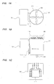
- Various solutions have been conventionally proposed for cooling the inverter. For example, as shown in FIGS. 1A and 1B , there has been known a construction in which the inverter is cooled by a cooling fan for cooling the motor.
- a cooling fan 108 is mounted to a rotational shaft 103 of a motor 101 for driving a pump.
- a circular guide cover 110 is provided on the motor 101 so as to cover the cooling fan 108.
- a gap is formed between the guide cover 110 and the motor 101. Therefore, gas flow, generated by rotation of the cooling fan 108, advances through the gap along an outer circumferential surface of the motor 101 to cool the motor 101, while a part of the gas flow cools the inverter 105.
- An axial flow fan or a diagonal flow fan is used as the cooling fan 108, because mounting of this type of fan is easy and its major purpose is to cool the motor 101.
- the inverter 105 is coupled to a side surface of the motor 101 through a support member 111.
- this support member 111 is typically arranged on a center line connecting the motor 101 to the inverter 105 when viewed from above.
- the support member 111 arranged in such a position prevents the gas flow delivered from the cooling fan 108 as shown in FIG. 1C , and as a result a cooling efficiency of the inverter 105 is lowered.
- use of a larger inverter 105 necessitates use of a larger support member 111, which would greatly disturb the gas flow for cooling the inverter 105.
- the inverter 105 When the axial flow fan is used as the cooling fan 108, the inverter 105 may not be cooled sufficiently because of a low flow rate of gas.
- the inverter 105 when used to drive the motor 101 for driving a pump requiring a large shaft power, is necessarily large.
- the axial flow fan cannot produce the gas flow powerful enough to cool such large inverter 105.
- the gas flow directly strikes the motor 101 firstly, and thereafter its secondary gas flow strikes the inverter 105. As a result, the cooling efficiency of the inverter 105 is lowered.
- the present invention has been made in order to solve the above-mentioned conventional drawbacks, and therefore it is an object of the present invention to provide a motor assembly having a cooling structure capable of sufficiently cooling an inverter adjacent to a motor.
- one aspect of the present invention provides a motor assembly including: a motor to be coupled to a pump; an inverter for changing a rotational speed of the motor; a cooling fan coupled to a rotational shaft of the motor and mounted to an end portion of the motor at an opposite side of the pump; a guide cover for guiding gas flow, generated by rotation of the cooling fan, to the inverter; and at least two support members coupling the inverter to a side surface of the motor.
- the support members are located on both sides of a center line connecting a central axis of the motor to a center of the inverter as viewed from an axial direction of the motor. A space serving as a passage of the gas flow from the cooling fan is formed between the support members.
- one of the at least two support members has a through-hole through which a power line extends.
- the inverter has a power switching element and a box for housing the power switching element therein, and the power switching element in the box is arranged adjacent to the passage of the gas flow.
- the cooling fan is a centrifugal fan.
- a part of the inverter is located radially outwardly of the cooling fan.
- a sound absorbing material or a damping material is attached to an inner surface of the guide cover.
- a top of the guide cover and a top of the inverter lie in the same plane.
- Another aspect of the present invention provides a pump apparatus including the above-described motor assembly and a pump which is driven by the motor assembly.
- the gas flow generated by the cooling fan advances along the surface of the inverter without being disturbed by the support members. Therefore, the inverter can be efficiently cooled by this gas flow.
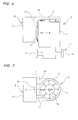
- FIG. 2 is a schematic view showing a pump apparatus including a motor assembly according to an embodiment of the present invention.
- This pump apparatus includes a pump 1 for delivering fluid and a motor assembly 2, according to the embodiment of the present invention, for driving the pump 1.
- the motor assembly 2 includes a motor 5 coupled to the pump 1, an inverter 6 for changing a rotational speed of the motor 5, and two support members 11 for coupling the inverter 6 to the motor 5.
- a synchronous motor which uses a permanent magnet in a rotor, is used as the motor 5.
- This type of motor i.e., permanent magnet motor
- This type of motor is more efficient than a general motor, and therefore has a characteristic that heat generation is low.
- another type of motor may be used in the motor assembly of the present invention.
- the pump 1 is driven by the motor assembly 2, so that the fluid is sucked through a suction opening 1a, pressured, and discharged through a discharge opening 1b.
- One example of the pump 1 is a centrifugal pump. However, another type of pump may be used.
- FIG. 3 is a plan view of the motor assembly shown in FIG. 2
- FIG. 4 is a view of the inverter and the support members shown in FIG. 2 as viewed from a direction indicated by arrow B.
- a cooling fan 8 is arranged on an upper portion of the motor 5 (i.e., an end portion at the opposite side of the pump). This cooling fan 8 is coupled to a rotational shaft 10 of the motor 5. Therefore, the cooling fan 8 is rotated together with the rotational shaft 10 of the motor 5.
- the inverter 6 includes a power switching element 15, a control board (not shown in the figures) for controlling action of the power switching element 15, and a box 17 for housing the power switching element 15 and the control board therein.
- the power switching element 15 is fixed to the box 17 such that the power switching element 15 is in contact with an inner surface of a bottom of the box 17.
- the bottom of the inverter 6 faces the motor 5, and the inverter 6 is arranged adjacent to the motor 5.
- the cooling fan 8 is a centrifugal fan which is configured to suck the fluid from an axis direction thereof and discharge the fluid radially outwardly.
- the centrifugal fan to be used include a radial fan, a turbo fan, and a sirocco fan. By using such centrifugal fan for the cooling fan 8, gas flow with a high flow rate can be formed.
- the radial fan is used as the cooling fan 8.
- FIG. 5A is a side view showing the guide cover 20
- FIG. 5B is a view of the guide cover shown in FIG. 5A as viewed from a direction indicated by arrow D.
- the guide cover 20 has a flat portion 20a having a gas intake (an air intake) 20c, and a side portion 20b having a U-shaped configuration when viewed from below.
- ambient gas typically air
- ambient gas flows into the guide cover 20 through the air intake 20c and is then delivered to the inverter 6 along the side portion 20b of the guide cover 20.
- a gap is formed between the guide cover 20 and the motor 5 when viewed from the axial direction of the motor 5.
- a part of the gas flow, generated by the rotation of the cooling fan 8, advances through this gap along an outer circumferential surface of the motor 5 to thereby cool the motor 5.
- the inverter 6 is coupled to a side surface of the motor 5 by two support members 11. As shown in FIG. 3 , these support members 11 are arranged on both sides of a center line (indicated by reference sign C) connecting a central axis of the motor 5 to a center of the inverter 6 when viewed from the axial direction of the motor 5. Specifically, these support members 11 are disposed at positions spaced apart from the center line C. As shown in FIG. 4 , each of the support members 11 has a plate shape, and extends along the rotational shaft 10 (central axis) of the motor 5 so as to avoid disturbing the gas flow.
- the two support members 11 are arranged symmetrically in such positions that the above-mentioned center line C is interposed between the support members 11.
- the power switching element 15 of the inverter 6 is located on the center line C.
- the two support members 11 are spaced apart from each other so as to form a space therebetween. This space serves as a passage of the gas flow delivered from the cooling fan 8.
- One of the two support members 11 has a through-hole 11a through which a power line extends from the inverter 6 to the motor 5.
- a part of the inverter 6 (an upper portion thereof) is located radially outwardly of the cooling fan 8. Therefore, the gas flow, generated by the rotation of the cooling fan 8, strikes the upper portion of the inverter 6 to change its direction of movement, and advances downward through the space between the inverter 6 and the motor 5.
- the support members 11 are spaced apart from the center line C so as not to prevent the movement of the gas flow, and the passage of the gas flow is formed between the support members 11 as shown in FIG. 4 .
- the inverter 6 is cooled by the gas flow that advances on its outer surface along the central axis of the motor 5.
- the centrifugal fan such as the radial fan
- the cooling fan 8 can generate strong gas flow and can thus further improve a cooling effect of the inverter 6.
- the gas flow, advancing through the space between the motor 5 and the inverter 6, can cool the motor 5 simultaneously.
- the power switching element 15 of the inverter 6 is located adjacent to the passage of the gas flow delivered from the cooling fan 8. Therefore, the gas, delivered from the cooling fan 8, can cool the power switching element 15. In particular, as shown in FIG. 2 , it is preferable that the power switching element 15 be located radially outwardly of the cooling fan 8. By arranging the power switching element 15 at such a position, the cooling effect of the power switching element 15 can be improved, because the gas flow strikes a wall surface of the box 17 lying at a back side of the power switching element 15.
- the inverter 6 and the guide cover 20 are disposed on the same plane (which is a virtual plane) perpendicular to the rotational shaft 10 of the motor 5. More specifically, a top of the inverter 6 (an end portion at the opposite side of the pump) and a top of the guide cover 20 (i.e., the flat portion 20a) lie in the same plane.
- the motor assembly 2 having such an arrangement can have an end surface with no concave and convex.
- the inverter 6 is located radially outwardly of the cooling fan 8.
- the inverter 6 may not be located radially outwardly of the cooling fan 8.
- the guide cover 20 preferably has the side portion 20b surrounding the cooling fan 8 in its entirety. The gas flow, formed by the cooling fan 8, strikes the side portion 20b of the guide cover 20 to change its direction of movement toward the inverter 6, so that the gas flows along the outer surface of the inverter 6.
- the power switching element 15 of the inverter 6 is arranged adjacent to the passage of the gas flow. Therefore, the power switching element 15 is cooled by the gas flow through the box 17 of the inverter 6.
- FIGS. 7A to 7C are views showing an example in which the inverter 6 is coupled to the side surface of the motor 5 by four support members 11.
- the number of support members 11 is not limited to two, and may be three or more.
- the four support members 11 are provided. More specifically, two pairs of support members 11 are arranged along the central axis of the motor 5.
- the passage for the gas flow delivered from the cooling fan 8 is formed between each pair of support members 11.
- One of the four support members 11 has the through-hole 11 a through which the power line extends. It is not necessary that all support members 11 have the same size.
- the support member 11 not having the through-hole 11a may be smaller than the support member 11 having the through-hole 11a.
- FIGS. 8A to 8C are views showing an example in which the inverter 6 is coupled to the side surface of the motor 5 by six support members 11.
- three pairs of support members 11 are arranged along the central axis of the motor 5.
- the support members 11 not having the through-hole 11 a may have a thin plate shape as shown in FIG. 8 .
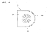
- FIG. 9 is a view showing an example in which the sound absorbing material or the damping material is attached to the inner surface of the side portion 20b of the guide cover 20.
- the sound absorbing material or the damping material is denoted by reference numeral 21.
- slightly larger guide cover 20 is preferably used, as compared with the case of not providing the sound absorbing material or the damping material.
- the sound absorbing material is a member which absorbs sounds by taking the sounds therein and converting sound energy into thermal energy.
- Examples of the sound absorbing material include sponge and urethane foam.
- the damping material is a member which reduces vibration of a solid material by converting vibration energy of the solid material into thermal energy. Examples of the damping member include a rubber plate and a plastic plate.
- the present invention is applicable to a motor assembly having a cooling structure for efficiently cooling an inverter.
Landscapes
- Engineering & Computer Science (AREA)
- Power Engineering (AREA)
- Microelectronics & Electronic Packaging (AREA)
- Motor Or Generator Cooling System (AREA)
- Structures Of Non-Positive Displacement Pumps (AREA)
Abstract
A motor assembly (2) includes a motor (5), an inverter (6) for changing rotational speed of the motor (5), a cooling fan (8) coupled to a rotational shaft (10) of the motor (5), a guide cover (20) for guiding a gas flow generated by rotation of the cooling fan (8) to the inverter (6), and at least two support members (11) coupling the inverter (6) to a side surface of the motor (5). The support members (11) are located on both sides of a center line (C) connecting a central axis of the motor (5) to a center of the inverter as viewed from an axial direction of the motor (5). A space serving as a passage of the gas flow from the cooling fan (8) is formed between the support members (11).
Description
- The present invention relates to a motor assembly and a pump apparatus, and especially relates to a motor assembly having a cooling structure for efficiently cooling an inverter.
- A motor is widely used as a drive source for driving a pump. Recently, an inverter-integrated pump motor, in which an inverter is mounted to a motor, is becoming mainstream. The inverter has a power switching element (e.g., Insulated Gate Bipolar Transistor (IGBT), power MOS FET, or the like). With use of such a power switching element, the inverter can change input power of the motor and can thus operate the motor at variable speeds.
- During driving of such pump motor, the inverter and the motor generate heat. In particular, the power switching element of the inverter generates high heat while it has a small surface area. As a result, the inverter is heated to have a high temperature. Various solutions have been conventionally proposed for cooling the inverter. For example, as shown in
FIGS. 1A and 1B , there has been known a construction in which the inverter is cooled by a cooling fan for cooling the motor. - In the example shown in
FIGS. 1A and 1B , acooling fan 108 is mounted to arotational shaft 103 of amotor 101 for driving a pump. Acircular guide cover 110 is provided on themotor 101 so as to cover thecooling fan 108. A gap is formed between theguide cover 110 and themotor 101. Therefore, gas flow, generated by rotation of thecooling fan 108, advances through the gap along an outer circumferential surface of themotor 101 to cool themotor 101, while a part of the gas flow cools theinverter 105. An axial flow fan or a diagonal flow fan is used as thecooling fan 108, because mounting of this type of fan is easy and its major purpose is to cool themotor 101. - However, in the conventional cooling structure shown in
FIGS. 1A and 1B , there exist the following drawbacks. Theinverter 105 is coupled to a side surface of themotor 101 through asupport member 111. From a viewpoint of facilitating its coupling structure, thissupport member 111 is typically arranged on a center line connecting themotor 101 to theinverter 105 when viewed from above. Thesupport member 111 arranged in such a position prevents the gas flow delivered from thecooling fan 108 as shown inFIG. 1C , and as a result a cooling efficiency of theinverter 105 is lowered. In particular, use of alarger inverter 105 necessitates use of alarger support member 111, which would greatly disturb the gas flow for cooling theinverter 105. - When the axial flow fan is used as the
cooling fan 108, theinverter 105 may not be cooled sufficiently because of a low flow rate of gas. In particular, theinverter 105, when used to drive themotor 101 for driving a pump requiring a large shaft power, is necessarily large. The axial flow fan cannot produce the gas flow powerful enough to cool suchlarge inverter 105. Furthermore, when the axial flow fan or the diagonal flow fan is used, the gas flow directly strikes themotor 101 firstly, and thereafter its secondary gas flow strikes theinverter 105. As a result, the cooling efficiency of theinverter 105 is lowered. -
- Japanese laid-open patent publication No.
2009-278807 - Japanese laid-open patent publication No.
2009-278809 - Japanese laid-open patent publication No.
2009-278811 - The present invention has been made in order to solve the above-mentioned conventional drawbacks, and therefore it is an object of the present invention to provide a motor assembly having a cooling structure capable of sufficiently cooling an inverter adjacent to a motor.
- In order to achieve the above-mentioned object, one aspect of the present invention provides a motor assembly including: a motor to be coupled to a pump; an inverter for changing a rotational speed of the motor; a cooling fan coupled to a rotational shaft of the motor and mounted to an end portion of the motor at an opposite side of the pump; a guide cover for guiding gas flow, generated by rotation of the cooling fan, to the inverter; and at least two support members coupling the inverter to a side surface of the motor. The support members are located on both sides of a center line connecting a central axis of the motor to a center of the inverter as viewed from an axial direction of the motor. A space serving as a passage of the gas flow from the cooling fan is formed between the support members.
- In a preferred aspect of the present invention, one of the at least two support members has a through-hole through which a power line extends.
In a preferred aspect of the present invention, the inverter has a power switching element and a box for housing the power switching element therein, and the power switching element in the box is arranged adjacent to the passage of the gas flow. - In a preferred aspect of the present invention, the cooling fan is a centrifugal fan.
In a preferred aspect of the present invention, a part of the inverter is located radially outwardly of the cooling fan.
In a preferred aspect of the present invention, a sound absorbing material or a damping material is attached to an inner surface of the guide cover.
In a preferred aspect of the present invention, a top of the guide cover and a top of the inverter lie in the same plane. - Another aspect of the present invention provides a pump apparatus including the above-described motor assembly and a pump which is driven by the motor assembly.
- According to the present invention, the gas flow generated by the cooling fan advances along the surface of the inverter without being disturbed by the support members. Therefore, the inverter can be efficiently cooled by this gas flow.
-
- [
FIG. 1A] FIG. 1A is a plan view showing a motor assembly having a conventional inverter cooling structure. - [
FIG. 1B] FIG. 1B is a schematic view of the motor assembly shown inFIG. 1 A . - [
FIG. 1C] FIG. 1C is a view of an inverter and a support member shown inFIG. 1 A as viewed from a direction indicated by arrow A. - [
FIG. 2] FIG. 2 is a schematic view showing a pump apparatus including a motor assembly according to an embodiment of the present invention. - [
FIG. 3] FIG. 3 is a plan view of the motor assembly shown inFIG. 2 . - [
FIG. 4] FIG. 4 is a view of an inverter and support members shown inFIG. 2 as viewed from a direction indicated by arrow B. - [
FIG. 5A] FIG. 5A is a side view showing a guide cover. - [
FIG. 5B] FIG. 5B is a view of the guide cover shown inFIG. 5A as viewed from a direction indicated by arrow D. - [
FIG. 6] FIG. 6 is a view showing an example of the motor assembly in which an upper end of the inverter lies below a cooling fan. - [
FIG. 7A] FIG. 7A is a view showing an example in which the inverter is coupled to a side surface of the motor by four support members. - [
FIG. 7B] FIG. 7B is a view showing the example in which the inverter is coupled to the side surface of the motor by the four support members. - [
FIG. 7C] FIG. 7C is a view showing the example in which the inverter is coupled to the side surface of the motor by the four support members. - [
FIG. 8A] FIG. 8A is a view showing an example in which the inverter is coupled to the side surface of the motor by six support members. - [
FIG. 8B] FIG. 8B is a view showing the example in which the inverter is coupled to the side surface of the motor by the six support members. - [
FIG. 8C] FIG. 8C is a view showing the example in which the inverter is coupled to the side surface of the motor by the six support members. - [
FIG. 9] FIG. 9 is a view showing an example in which a sound absorbing material or a damping material is attached on an inner surface of the guide cover. - Hereinafter, embodiments of the present invention will be explained with reference to the figures.
FIG. 2 is a schematic view showing a pump apparatus including a motor assembly according to an embodiment of the present invention. This pump apparatus includes apump 1 for delivering fluid and amotor assembly 2, according to the embodiment of the present invention, for driving thepump 1. Themotor assembly 2 includes amotor 5 coupled to thepump 1, aninverter 6 for changing a rotational speed of themotor 5, and twosupport members 11 for coupling theinverter 6 to themotor 5. - A synchronous motor, which uses a permanent magnet in a rotor, is used as the
motor 5. This type of motor (i.e., permanent magnet motor) is more efficient than a general motor, and therefore has a characteristic that heat generation is low. However, another type of motor may be used in the motor assembly of the present invention. - The
pump 1 is driven by themotor assembly 2, so that the fluid is sucked through asuction opening 1a, pressured, and discharged through adischarge opening 1b. One example of thepump 1 is a centrifugal pump. However, another type of pump may be used. -
FIG. 3 is a plan view of the motor assembly shown inFIG. 2 , andFIG. 4 is a view of the inverter and the support members shown inFIG. 2 as viewed from a direction indicated by arrow B. A coolingfan 8 is arranged on an upper portion of the motor 5 (i.e., an end portion at the opposite side of the pump). This coolingfan 8 is coupled to arotational shaft 10 of themotor 5. Therefore, the coolingfan 8 is rotated together with therotational shaft 10 of themotor 5. - The
inverter 6 includes apower switching element 15, a control board (not shown in the figures) for controlling action of thepower switching element 15, and abox 17 for housing thepower switching element 15 and the control board therein. Thepower switching element 15 is fixed to thebox 17 such that thepower switching element 15 is in contact with an inner surface of a bottom of thebox 17. The bottom of theinverter 6 faces themotor 5, and theinverter 6 is arranged adjacent to themotor 5. - The cooling
fan 8 is a centrifugal fan which is configured to suck the fluid from an axis direction thereof and discharge the fluid radially outwardly. Examples of the centrifugal fan to be used include a radial fan, a turbo fan, and a sirocco fan. By using such centrifugal fan for the coolingfan 8, gas flow with a high flow rate can be formed. In the example shown in the figures, the radial fan is used as the coolingfan 8. - As shown in
FIG. 3 , aguide cover 20 is provided above themotor 5 so as to cover the coolingfan 8. This guide cover 20 serves to guide the gas flow, generated by the rotation of the coolingfan 8, to theinverter 6.FIG. 5A is a side view showing theguide cover 20, andFIG. 5B is a view of the guide cover shown inFIG. 5A as viewed from a direction indicated by arrow D. Theguide cover 20 has aflat portion 20a having a gas intake (an air intake) 20c, and aside portion 20b having a U-shaped configuration when viewed from below. As the coolingfan 8 is rotated, ambient gas (typically air) flows into theguide cover 20 through theair intake 20c and is then delivered to theinverter 6 along theside portion 20b of theguide cover 20. As shown inFIG. 3 , a gap is formed between theguide cover 20 and themotor 5 when viewed from the axial direction of themotor 5. A part of the gas flow, generated by the rotation of the coolingfan 8, advances through this gap along an outer circumferential surface of themotor 5 to thereby cool themotor 5. - The
inverter 6 is coupled to a side surface of themotor 5 by twosupport members 11. As shown inFIG. 3 , thesesupport members 11 are arranged on both sides of a center line (indicated by reference sign C) connecting a central axis of themotor 5 to a center of theinverter 6 when viewed from the axial direction of themotor 5. Specifically, thesesupport members 11 are disposed at positions spaced apart from the center line C. As shown inFIG. 4 , each of thesupport members 11 has a plate shape, and extends along the rotational shaft 10 (central axis) of themotor 5 so as to avoid disturbing the gas flow. - In the present embodiment, the two
support members 11 are arranged symmetrically in such positions that the above-mentioned center line C is interposed between thesupport members 11. Thepower switching element 15 of theinverter 6 is located on the center line C. The twosupport members 11 are spaced apart from each other so as to form a space therebetween. This space serves as a passage of the gas flow delivered from the coolingfan 8. One of the twosupport members 11 has a through-hole 11a through which a power line extends from theinverter 6 to themotor 5. - A part of the inverter 6 (an upper portion thereof) is located radially outwardly of the cooling
fan 8. Therefore, the gas flow, generated by the rotation of the coolingfan 8, strikes the upper portion of theinverter 6 to change its direction of movement, and advances downward through the space between theinverter 6 and themotor 5. Thesupport members 11 are spaced apart from the center line C so as not to prevent the movement of the gas flow, and the passage of the gas flow is formed between thesupport members 11 as shown inFIG. 4 . Theinverter 6 is cooled by the gas flow that advances on its outer surface along the central axis of themotor 5. - In this embodiment, the centrifugal fan, such as the radial fan, is used as the cooling
fan 8, as described above. Therefore, the coolingfan 8 can generate strong gas flow and can thus further improve a cooling effect of theinverter 6. Moreover, the gas flow, advancing through the space between themotor 5 and theinverter 6, can cool themotor 5 simultaneously. - The
power switching element 15 of theinverter 6 is located adjacent to the passage of the gas flow delivered from the coolingfan 8. Therefore, the gas, delivered from the coolingfan 8, can cool thepower switching element 15. In particular, as shown inFIG. 2 , it is preferable that thepower switching element 15 be located radially outwardly of the coolingfan 8. By arranging thepower switching element 15 at such a position, the cooling effect of thepower switching element 15 can be improved, because the gas flow strikes a wall surface of thebox 17 lying at a back side of thepower switching element 15. - In the embodiment shown in
FIG. 2 , theinverter 6 and theguide cover 20 are disposed on the same plane (which is a virtual plane) perpendicular to therotational shaft 10 of themotor 5. More specifically, a top of the inverter 6 (an end portion at the opposite side of the pump) and a top of the guide cover 20 (i.e., theflat portion 20a) lie in the same plane. Themotor assembly 2 having such an arrangement can have an end surface with no concave and convex. - In the embodiment shown in
FIG. 2 , a part of theinverter 6 is located radially outwardly of the coolingfan 8. In another embodiment, as shown inFIG. 6 , theinverter 6 may not be located radially outwardly of the coolingfan 8. In this case, theguide cover 20 preferably has theside portion 20b surrounding the coolingfan 8 in its entirety. The gas flow, formed by the coolingfan 8, strikes theside portion 20b of theguide cover 20 to change its direction of movement toward theinverter 6, so that the gas flows along the outer surface of theinverter 6. In this case also, thepower switching element 15 of theinverter 6 is arranged adjacent to the passage of the gas flow. Therefore, thepower switching element 15 is cooled by the gas flow through thebox 17 of theinverter 6. -
FIGS. 7A to 7C are views showing an example in which theinverter 6 is coupled to the side surface of themotor 5 by foursupport members 11. As shown inFIGS. 7A to 7C , the number ofsupport members 11 is not limited to two, and may be three or more. In the embodiment shown inFIGS. 7A to 7C , the foursupport members 11 are provided. More specifically, two pairs ofsupport members 11 are arranged along the central axis of themotor 5. As is the case in the embodiment shown inFIG. 4 , the passage for the gas flow delivered from the coolingfan 8 is formed between each pair ofsupport members 11. One of the foursupport members 11 has the through-hole 11 a through which the power line extends. It is not necessary that allsupport members 11 have the same size. For example, thesupport member 11 not having the through-hole 11a may be smaller than thesupport member 11 having the through-hole 11a. -
FIGS. 8A to 8C are views showing an example in which theinverter 6 is coupled to the side surface of themotor 5 by sixsupport members 11. In the embodiment shown inFIG. 8 , three pairs ofsupport members 11 are arranged along the central axis of themotor 5. Thesupport members 11 not having the through-hole 11 a may have a thin plate shape as shown inFIG. 8 . - During operation of the motor assembly 22, the
motor 5 and the coolingfan 8 generate noises. Therefore, in order to reduce such noises, a sound absorbing material or a damping material is preferably attached to an inner surface of theguide cover 20.FIG. 9 is a view showing an example in which the sound absorbing material or the damping material is attached to the inner surface of theside portion 20b of theguide cover 20. InFIG. 9 , the sound absorbing material or the damping material is denoted byreference numeral 21. In a case of using such configuration, slightlylarger guide cover 20 is preferably used, as compared with the case of not providing the sound absorbing material or the damping material. - The sound absorbing material is a member which absorbs sounds by taking the sounds therein and converting sound energy into thermal energy. Examples of the sound absorbing material include sponge and urethane foam. The damping material is a member which reduces vibration of a solid material by converting vibration energy of the solid material into thermal energy. Examples of the damping member include a rubber plate and a plastic plate.
- The previous description of embodiments is provided to enable a person skilled in the art to make and use the present invention. Moreover, various modifications to these embodiments will be readily apparent to those skilled in the art, and the generic principles and specific examples defined herein may be applied to other embodiments. Therefore, the present invention is not intended to be limited to the embodiments described herein but is to be accorded the widest scope as defined by limitation of the claims and equivalents.
- The present invention is applicable to a motor assembly having a cooling structure for efficiently cooling an inverter.
Claims (8)
- A motor assembly comprising:a motor to be coupled to a pump;an inverter for changing a rotational speed of said motor;a cooling fan coupled to a rotational shaft of said motor and mounted to an end portion of said motor at an opposite side of the pump;a guide cover for guiding gas flow, generated by rotation of said cooling fan, to said inverter; andat least two support members coupling said inverter to a side surface of said motor;wherein said support members are located on both sides of a center line connecting a central axis of said motor to a center of said inverter as viewed from an axial direction of said motor, andwherein a space serving as a passage of the gas flow from said cooling fan is formed between said support members.
- The motor assembly according to claim 1, wherein one of said at least two support members has a through-hole through which a power line extends.
- The motor assembly according to claim 1 or 2:wherein said inverter has a power switching element and a box for housing the power switching element therein; andwherein said power switching element in said box is arranged adjacent to said passage of the gas flow.
- The motor assembly according to any one of claims 1 through 3, wherein said cooling fan is a centrifugal fan.
- The motor assembly according to any one of claims 1 through 4, wherein a part of said inverter is located radially outwardly of said cooling fan.
- The motor assembly according to any one of claims 1 through 5, wherein a sound absorbing material or a damping material is attached to an inner surface of said guide cover.
- The motor assembly according to any one of claims 1 through 6, wherein a top of said guide cover and a top of said inverter lie in the same plane.
- A pump apparatus comprising:said motor assembly according to any one of claims 1 through 7; anda pump driven by said motor assembly.
Applications Claiming Priority (2)
| Application Number | Priority Date | Filing Date | Title |
|---|---|---|---|
| JP2010227304A JP5677010B2 (en) | 2010-10-07 | 2010-10-07 | Motor assembly and pump device |
| PCT/JP2011/073051 WO2012046794A1 (en) | 2010-10-07 | 2011-10-06 | Motor assembly and pump device |
Publications (1)
| Publication Number | Publication Date |
|---|---|
| EP2626984A1 true EP2626984A1 (en) | 2013-08-14 |
Family
ID=45927788
Family Applications (1)
| Application Number | Title | Priority Date | Filing Date |
|---|---|---|---|
| EP11830726.3A Withdrawn EP2626984A1 (en) | 2010-10-07 | 2011-10-06 | Motor assembly and pump device |
Country Status (5)
| Country | Link |
|---|---|
| US (1) | US9190887B2 (en) |
| EP (1) | EP2626984A1 (en) |
| JP (1) | JP5677010B2 (en) |
| CN (1) | CN103155379A (en) |
| WO (1) | WO2012046794A1 (en) |
Families Citing this family (10)
| Publication number | Priority date | Publication date | Assignee | Title |
|---|---|---|---|---|
| EP2950429B1 (en) * | 2013-01-25 | 2021-03-10 | Daikin Industries, Ltd. | Fluid device |
| JP6153474B2 (en) * | 2014-01-08 | 2017-06-28 | 住友重機械工業株式会社 | Gear motor and reducer |
| US9840143B1 (en) | 2015-05-20 | 2017-12-12 | Hydro-Gear Limited Partnership | Cooling pump assembly and cooling system for utility vehicle |
| US10358040B1 (en) | 2015-06-01 | 2019-07-23 | Hydro-Gear Limited Partnership | Drive assembly and system for utility vehicle |
| US10106027B1 (en) | 2015-06-01 | 2018-10-23 | Hydro-Gear Limited Partnership | Generator/cooling assembly and system for utility vehicle |
| US10391854B1 (en) | 2015-06-15 | 2019-08-27 | Hydro-Gear Limited Partnership | Drive and cooling system for utility vehicle |
| US10093169B1 (en) | 2015-07-09 | 2018-10-09 | Hydro-Gear Limited Partnership | Power and cooling system for utility vehicle |
| JP6797541B2 (en) * | 2016-03-31 | 2020-12-09 | 株式会社荏原製作所 | Heat exchanger |
| JP6733405B2 (en) * | 2016-07-29 | 2020-07-29 | 三菱自動車工業株式会社 | Electric vehicle cooling structure |
| TWI661658B (en) * | 2018-06-22 | 2019-06-01 | 群光電能科技股份有限公司 | Motor device and heat dissipation device |
Family Cites Families (16)
| Publication number | Priority date | Publication date | Assignee | Title |
|---|---|---|---|---|
| JPS5545677U (en) * | 1978-09-21 | 1980-03-25 | ||
| JPS59165941A (en) | 1983-03-11 | 1984-09-19 | Hitachi Ltd | Inverter-driven rotating electric machine |
| DE3642724A1 (en) | 1986-12-13 | 1988-06-23 | Grundfos Int | ELECTRIC MOTOR WITH A FREQUENCY CONVERTER TO CONTROL THE MOTOR OPERATING SIZES |
| JPH04242A (en) | 1990-04-05 | 1992-01-06 | Mitsubishi Electric Corp | Motor integrated with amplifier |
| US5763969A (en) * | 1996-11-14 | 1998-06-09 | Reliance Electric Industrial Company | Integrated electric motor and drive system with auxiliary cooling motor and asymmetric heat sink |
| FR2756676A1 (en) * | 1996-12-03 | 1998-06-05 | Centor | Common cooling technique for variable speed motor/driver |
| JPH11234954A (en) | 1998-02-18 | 1999-08-27 | Toshiba Corp | Electric motor |
| JP2001275301A (en) | 2000-03-27 | 2001-10-05 | Matsushita Electric Ind Co Ltd | Fully enclosed fan motor |
| JP2002272180A (en) * | 2001-03-15 | 2002-09-20 | Sumitomo Heavy Ind Ltd | Induction motor |
| JP2007306741A (en) | 2006-05-12 | 2007-11-22 | Toshiba Corp | Control device integrated motor |
| JP2008271730A (en) | 2007-04-23 | 2008-11-06 | Toshiba Corp | Electric motor |
| US7923875B2 (en) * | 2008-04-25 | 2011-04-12 | A.O. Smith Corporation | Assembly for an electric machine |
| JP5189891B2 (en) | 2008-05-16 | 2013-04-24 | 株式会社荏原製作所 | Motor assembly and pump device |
| JP5373315B2 (en) * | 2008-05-16 | 2013-12-18 | 株式会社荏原製作所 | Motor assembly and pump device |
| JP5215728B2 (en) | 2008-05-16 | 2013-06-19 | 株式会社荏原製作所 | Motor assembly and pump device |
| US7977832B2 (en) * | 2008-05-21 | 2011-07-12 | Nidec Motor Corporation | Cooling system for a motor and associated electronics |
-
2010
- 2010-10-07 JP JP2010227304A patent/JP5677010B2/en not_active Expired - Fee Related
-
2011
- 2011-10-06 WO PCT/JP2011/073051 patent/WO2012046794A1/en not_active Ceased
- 2011-10-06 EP EP11830726.3A patent/EP2626984A1/en not_active Withdrawn
- 2011-10-06 CN CN2011800483961A patent/CN103155379A/en active Pending
- 2011-10-06 US US13/876,709 patent/US9190887B2/en not_active Expired - Fee Related
Non-Patent Citations (1)
| Title |
|---|
| See references of WO2012046794A1 * |
Also Published As
| Publication number | Publication date |
|---|---|
| WO2012046794A1 (en) | 2012-04-12 |
| US9190887B2 (en) | 2015-11-17 |
| CN103155379A (en) | 2013-06-12 |
| JP2012085385A (en) | 2012-04-26 |
| JP5677010B2 (en) | 2015-02-25 |
| US20130181554A1 (en) | 2013-07-18 |
Similar Documents
| Publication | Publication Date | Title |
|---|---|---|
| US9190887B2 (en) | Motor assembly and pump apparatus including a cooling fan for cooling an inverter | |
| JP5215728B2 (en) | Motor assembly and pump device | |
| JP5189891B2 (en) | Motor assembly and pump device | |
| JP3204950U (en) | Inflator device for heat dissipation of motor | |
| CN107196460B (en) | Electric power unit | |
| US20190301442A1 (en) | Oscillating fan and electronic device having the same | |
| US9800118B2 (en) | Self-cooled motor | |
| US9022751B2 (en) | Advection fan and an impeller thereof | |
| US20130323096A1 (en) | Diagonal fan | |
| JP5238348B2 (en) | Motor assembly and pump device | |
| KR101331731B1 (en) | Motor assembly for vacuum cleaner | |
| CN105411433A (en) | Food processor's circulation ventilation device | |
| JP2000283089A (en) | Fan motor | |
| US9800117B2 (en) | Self-cooled motor | |
| JP2009511806A (en) | Cooler fan for vehicle | |
| JP5373315B2 (en) | Motor assembly and pump device | |
| JP2012110151A (en) | Motor assembly and pump device | |
| JP6678302B2 (en) | Temperature control unit, temperature control system, vehicle | |
| CN204761231U (en) | Electric machinery | |
| US20200004303A1 (en) | Heat dissipation module | |
| JP2009203837A (en) | Centrifugal fan | |
| JP2005273592A (en) | Centrifugal fan | |
| JP6470055B2 (en) | Electric blower and electric vacuum cleaner using the same | |
| JP2009278808A (en) | Motor assembly and pump apparatus | |
| JP2012255412A (en) | Electric blower and vacuum cleaner using the same |
Legal Events
| Date | Code | Title | Description |
|---|---|---|---|
| PUAI | Public reference made under article 153(3) epc to a published international application that has entered the european phase |
Free format text: ORIGINAL CODE: 0009012 |
|
| 17P | Request for examination filed |
Effective date: 20130411 |
|
| AK | Designated contracting states |
Kind code of ref document: A1 Designated state(s): AL AT BE BG CH CY CZ DE DK EE ES FI FR GB GR HR HU IE IS IT LI LT LU LV MC MK MT NL NO PL PT RO RS SE SI SK SM TR |
|
| DAX | Request for extension of the european patent (deleted) | ||
| STAA | Information on the status of an ep patent application or granted ep patent |
Free format text: STATUS: THE APPLICATION HAS BEEN WITHDRAWN |
|
| 18W | Application withdrawn |
Effective date: 20160712 |