EP2626976A2 - Rotary electric machine - Google Patents
Rotary electric machine Download PDFInfo
- Publication number
- EP2626976A2 EP2626976A2 EP13151559.5A EP13151559A EP2626976A2 EP 2626976 A2 EP2626976 A2 EP 2626976A2 EP 13151559 A EP13151559 A EP 13151559A EP 2626976 A2 EP2626976 A2 EP 2626976A2
- Authority
- EP
- European Patent Office
- Prior art keywords
- permanent magnets
- magnetic pole
- rotor core
- pole portions
- stator core
- Prior art date
- Legal status (The legal status is an assumption and is not a legal conclusion. Google has not performed a legal analysis and makes no representation as to the accuracy of the status listed.)
- Withdrawn
Links
Images




Classifications
-
- H—ELECTRICITY
- H02—GENERATION; CONVERSION OR DISTRIBUTION OF ELECTRIC POWER
- H02K—DYNAMO-ELECTRIC MACHINES
- H02K1/00—Details of the magnetic circuit
- H02K1/06—Details of the magnetic circuit characterised by the shape, form or construction
-
- H—ELECTRICITY
- H02—GENERATION; CONVERSION OR DISTRIBUTION OF ELECTRIC POWER
- H02K—DYNAMO-ELECTRIC MACHINES
- H02K1/00—Details of the magnetic circuit
- H02K1/06—Details of the magnetic circuit characterised by the shape, form or construction
- H02K1/22—Rotating parts of the magnetic circuit
- H02K1/27—Rotor cores with permanent magnets
- H02K1/2706—Inner rotors
- H02K1/272—Inner rotors the magnetisation axis of the magnets being perpendicular to the rotor axis
- H02K1/274—Inner rotors the magnetisation axis of the magnets being perpendicular to the rotor axis the rotor consisting of two or more circumferentially positioned magnets
- H02K1/2753—Inner rotors the magnetisation axis of the magnets being perpendicular to the rotor axis the rotor consisting of two or more circumferentially positioned magnets the rotor consisting of magnets or groups of magnets arranged with alternating polarity
- H02K1/276—Magnets embedded in the magnetic core, e.g. interior permanent magnets [IPM]
- H02K1/2766—Magnets embedded in the magnetic core, e.g. interior permanent magnets [IPM] having a flux concentration effect
-
- H—ELECTRICITY
- H02—GENERATION; CONVERSION OR DISTRIBUTION OF ELECTRIC POWER
- H02K—DYNAMO-ELECTRIC MACHINES
- H02K1/00—Details of the magnetic circuit
- H02K1/06—Details of the magnetic circuit characterised by the shape, form or construction
- H02K1/22—Rotating parts of the magnetic circuit
- H02K1/27—Rotor cores with permanent magnets
- H02K1/2706—Inner rotors
- H02K1/272—Inner rotors the magnetisation axis of the magnets being perpendicular to the rotor axis
- H02K1/274—Inner rotors the magnetisation axis of the magnets being perpendicular to the rotor axis the rotor consisting of two or more circumferentially positioned magnets
- H02K1/2753—Inner rotors the magnetisation axis of the magnets being perpendicular to the rotor axis the rotor consisting of two or more circumferentially positioned magnets the rotor consisting of magnets or groups of magnets arranged with alternating polarity
- H02K1/278—Surface mounted magnets; Inset magnets
Definitions
- Disclosed embodiments relate to a rotary electric machine.
- Japanese Patent Laid-open Publication No. H1-286758 discloses an electric motor (rotary electric machine) including a rotor core having a plurality of permanent magnets.
- the permanent magnets are arranged at predetermined intervals in a circumferential manner on the outer periphery of the rotor core.
- the rotor core between the adjacent permanent magnets is formed in a shape of protrusion. That is, the permanent magnets and the protruding portions of the rotor core are alternately arranged one by one.
- the d-axis means an axis is in a direction of a main magnetic flux
- the q-axis means an axis is in a direction electrically perpendicular to the d-axis.
- the disclosed embodiments provide a rotary electric machine capable of obtaining a wide range of constant output.
- a rotary electric machine including a rotor core in which first magnetic pole portions having permanent magnets and second magnetic pole portions having no permanent magnets are alternately arranged in a circumferential direction; and a stator core which is arranged to face an outer periphery of the rotor core, wherein the rotor core is configured such that an average gap length between the stator core and the second magnetic pole portions is larger than an average gap length between the stator core and the first magnetic pole portions.
- the motor 100 is an example of "rotary electric machine”.
- the motor 100 includes a stator 1 and a rotor 2.
- the stator 1 is arranged so as to face an outer peripheral portion of the rotor 2 (rotor core 21).
- the stator 1 also includes a stator core 11 and windings 12. At an inner side of the stator core 11, a plurality of slots 13 are formed.
- the rotor 2 includes the rotor core 21, a shaft 22, and permanent magnets 23.
- the rotor core 21 includes a plurality of first magnetic pole portions 24 having the permanent magnets 23 and a plurality of second magnetic pole portions 25 having no permanent magnets 23 which are alternately arranged one by one in a circumferential manner.
- each of the second magnetic pole portions 25 is configured as a protruding portion of the rotor core 21 located between two permanent magnets 23 adjacent to each other.
- a surface 23a of each of the permanent magnets 23 on the side of the stator core 11 is formed in a convex (arcuate) shape toward the stator core 11 when viewed from the axial direction.
- the radius of curvature of the surface 23a is smaller than that of an inner peripheral portion of the stator core 11.
- Both side surfaces 23b of the permanent magnet 23 in the circumferential direction of the rotor and a surface 23c of the permanent magnet 23 on the inner peripheral side of the rotor core 21 are formed in a linear shape (flat surface shape) when viewed from the axial direction.
- the permanent magnet 23 has a shape such that a thickness t2 of the central portion in the circumferential direction is larger than a thickness (i.e., length of the side surfaces 23b in the circumferential direction of the rotor) t1 of the end portion in the circumferential direction. Further, as shown in FIGS. 1 and 2 , the permanent magnets 23 are disposed substantially equidistant in the circumferential direction. The thickness of the permanent magnets 23 in the radial direction of the rotor is larger than a minimum interval L1 between the permanent magnets 23 of the two first magnetic pole portions 24 adjacent to each other (distance on the innermost peripheral side between the two adjacent permanent magnets 23). Additionally, the permanent magnet 23 is constituted by a ferrite permanent magnet.
- the permanent magnets 23 are embedded along the circumferential direction in the vicinity of the outer periphery of the rotor core 21. More specifically, the permanent magnets 23 are arranged on mounting portions 21a provided at the outer peripheral portion of the rotor core 21. As shown in FIG. 4 , the mounting portions 21a are formed in a groove shape opened on the side of the stator core 11. Thus, as shown in FIG. 2 , a portion (portion other than both end portions of the permanent magnet 23) of the surface 23a of the permanent magnet 23 on the side of the stator core 11 is exposed.
- each of the mounting portions 21a includes side portions 21b in contact with the side surfaces 23b (see FIG. 2 ) of the permanent magnet 23 and having a straight line shape when viewed from the axial direction, a bottom portion 21c in contact with the surface 23c (see FIG. 2 ) of the permanent magnet 23 on the inner peripheral side of the rotor core 21 and having a straight line shape when viewed from the axial direction.
- Each of the mounting portions 21a further includes claw portions 21d engaging with opposite end portions of the surface 23a (see FIG. 2 ) of the permanent magnet 23 in the circumferential direction. Further, the claw portions 21d have a function to prevent the permanent magnet 23 from popping out of the rotor core 21 when the rotor core 21 is rotated.
- the rotor core 21 is configured to have an average value of a gap length L2 between the second magnetic pole portions 25 and the stator core 11 larger than an average value of a gap length L3 between the first magnetic pole portions 24 and the stator core 11.
- the surface 23a on the side of the stator core 11 is formed in a circular arc shape having a radius of curvature smaller than that of the inner periphery of the stator core 11.
- the permanent magnet 23 is the closest to the stator core 11 in the central portion of the permanent magnet 23 in the circumferential direction.
- the gap length L3 between the stator core 11 and a portion of the permanent magnet 23 closest thereto is about 0.4 mm.
- the outer peripheral surface of each of the second magnetic pole portions 25 is configured to have a radius of curvature substantially the same as the stator core 11.
- the gap length L2 between the stator core 11 and the second magnetic pole portions 25 is substantially equal along the circumferential direction.
- the gap length L2 between the stator core 11 and the second magnetic pole portions 25 is about 1 mm.
- notches 26 are provided in portions of the second magnetic pole portions 25 on the side of the permanent magnets 23.
- the notches 26 are formed so as to extend in the axial direction (perpendicular to the paper surface) of the rotor core 21.
- the notches 26 are provided in each of the second magnetic pole portions 25.
- the notches 26 include a notch 26a which is provided in a portion of the second magnetic pole portion 25 adjacent to the permanent magnet 23 in one circumferential direction (direction of arrow R1), and a notch 26b which is provided at a portion of the second magnetic pole portion 25 adjacent to the permanent magnet 23 in the other circumferential direction (direction of arrow R2).
- a thickness L4 (see FIG. 2 ) of a portion 21e located between the notch 26a and the side surface 23b of the permanent magnet 23 adjacent to the notch 26a is smaller than a width L5 (length in the direction perpendicular to the radial direction) (see FIG. 2 ) of the second magnetic pole portion 25 between the notches 26a and 26b.
- a thickness L6 (see FIG. 2 ) of a portion 21f located between the notch 26b and the side surface 23b of the permanent magnet 23 adjacent to the notch 26b is smaller than the width L5 (length in the direction perpendicular to the radial direction) (see FIG.
- the thickness L4 (L6) of the portion 21e (21f) of the rotor core 21 is substantially equal to a length L7 of the claw portions 21d of the rotor core 21 in the radial direction.
- Each of the notches 26 is formed in a substantially V shape such that a width W1 of the notch 26 is gradually reduced toward the inner peripheral side of the rotor core 21 when viewed from the axial direction.
- the bottom end 26c of the notch 26 on the inner peripheral side of the rotor core 21 is located radially outward of the bottom end 23d of the side surface 23b of the permanent magnet 23 on the inner peripheral side of the rotor core 21.
- the bottom end 26c of the notch 26 may be located radially at a same position as that of the bottom end 23d of the permanent magnet 23 in the rotor core 21.
- the bottom end 26c of the notch 26 is located radially inward of a midpoint (point A) of the side surface 23b of the permanent magnet 23 in a thickness direction thereof.
- a surface 26d (26e) of the notch 26, i.e., the notch 26a (26b), opposite to the permanent magnets 23 is disposed in a direction along the q-axis of the motor 100. That is, the inner surface 26d of the notch 26a and the inner surface 26e of the notch 26b are disposed to be substantially parallel to the q-axis. Further, the q-axis means an axis in a direction electrically perpendicular to the d-axis which is in a direction of a main magnetic flux. Further, an inner surface 26f (inner surface 26g) of the notch 26 on the side of the permanent magnet 23 is arranged in a direction (direction intersecting the q-axis) substantially parallel to the side surface 23b of the permanent magnet 23.
- a rotor core 221 is configured such that an average value of a gap length L8 between a stator core 211 and a second magnetic pole portion 225 is equal to an average value of a gap length L9 between the stator core 211 and a first magnetic pole portion 224.
- magnetic flux due to the d-axis current is generated to pass through the permanent magnets 223a and 223b in the rotor core 221. Further, magnetic flux caused by the q-axis current is generated to respectively pass along the inside and outside of the V-shaped arrangement of the permanent magnets 223a and 223b in the rotor core 221.
- the magnetic flux due to the d-axis current is generated to pass through the two adjacent permanent magnets 23 in the rotor core 21.
- the magnetic flux due to the q-axis current is generated to pass around the permanent magnet 23 in the inner peripheral side of the rotor core 21.
- the magnetic flux due to the q-axis current is suppressed from occurring in a portion of the rotor core 21 located radially outward of the permanent magnets 23.
- the thickness of the permanent magnets 23 in the direction of the d-axis magnetic flux passing through the permanent magnets 23 is larger than the minimum interval L1 between two adjacent permanent magnets 23.
- the q-axis inductance Lq is sharply decreased compared to the case of the low load. It is considered that this is because in the motor 200 according to the comparative example, two permanent magnets 223a and 223b are arranged in a V shape, and when the current is increased, the magnetic flux in the rotor core 221 is saturated on the inside and outside of the V-shaped arrangement of the permanent magnets 223a and 223b. Further, in the motor 200 according to the comparative example, the d-axis inductance Ld decreases gradually as the current flowing through the windings 212 increases and then becomes substantially constant in the case of the low load.
- the q-axis inductance Lq when the current flowing through the windings 12 is relatively small (about 20 A - about 80 A) (low load), the q-axis inductance Lq is about 0.35 mH - about 0.4 mH, and is smaller than the q-axis inductance Lq (about 0.5 mH - about 0.55 mH) of the motor 200 according to the comparative example. This is considered to be due to the following reasons.
- the rotor core 21 is configured such that the average value of the gap length L2 between the stator core 11 and the second magnetic pole portions 25 is larger than that of the gap length L3 between the stator core 11 and the first magnetic pole portions 24. Accordingly, the magnetic flux caused by the q-axis current is difficult to pass through a space (air) between the stator core 11 and the second magnetic pole portions 25 compared to the case of the comparative example. As a result, the q-axis inductance Lq in the case of the first embodiment is smaller than that of the comparative example.
- the permanent magnets 23 are arranged in the vicinity of the outer periphery of the rotor core 21, so that, unlike the conventional motor 200, the q-axis inductance Lq is suppressed from occurring in the outer peripheral side of the permanent magnets 23, and the q-axis inductance Lq is reduced correspondingly. Meanwhile, in the first embodiment, while the q-axis inductance Lq is reduced at the high load compared with at the low load, the reduction degree of the q-axis inductance Lq is lower as compared to the conventional motor 200.
- the d-axis inductance Ld decreases gradually as the current flowing through the windings 12 increases, and is then substantially constant.
- the d-axis inductance Ld of the motor 100 according to the first embodiment is smaller than that of the d-axis inductance Ld of the motor 200 according to the comparative example. This is considered to be due to the following reasons. That is, since a thickness t2 of the permanent magnets 23 corresponds to about twice the thickness of the permanent magnets 223a and 223b of the motor 200 according to the comparative example, the magnetic flux due to the d-axis current is difficult to pass through the d-axis path. As a result, it is considered that the d-axis inductance Ld becomes smaller.
- a difference between the d-axis inductance Ld and the q-axis inductance Lq of the motor 100 according to the first embodiment is larger than a difference between the d-axis inductance Ld and the q-axis inductance Lq of the motor 200 according to the comparative example. That is, in the motor 100 according to the first embodiment, it is possible to obtain a reluctance torque greater than that of the motor 200 according to the comparative example.
- the rotor core 21 is configured such that the average value of the gap length L2 between the stator core 11 and the second magnetic pole portions 25 is larger than that of the gap length L3 between the stator core 11 and the first magnetic pole portions 24. Accordingly, the magnetic flux (magnetic flux due to the q-axis current) becomes difficult to pass through a space (air) between the stator core 11 and the second magnetic pole portions 25 by an increase in the average value of the gap length L2 between the second magnetic pole portions 25 and the stator core 11. As a result, it is possible to reduce the q-axis inductance Lq at a low load.
- the permanent magnets 23 are embedded in the vicinity of the outer periphery of the rotor core 21. That is, a length of the permanent magnets 23 in the circumferential direction of the rotor core 21 is larger than a length (i.e., a thickness of the permanent magnets 23) in the radial direction of the rotor.
- a length of the permanent magnets 23 in the circumferential direction of the rotor core 21 is larger than a length (i.e., a thickness of the permanent magnets 23) in the radial direction of the rotor.
- the permanent magnets 23 are embedded along the circumferential direction in the vicinity of the outer periphery of the rotor core 21.
- the two permanent magnets 223a and 223b are arranged in a V shape, the two permanent magnets 223a and 223b are closer to each other on the inner peripheral side (base of the V shape) of the rotor core 221.
- the permanent magnets 23 are configured to have a shape such that the thickness t2 of the central portion in the circumferential direction is larger than the thickness t1 of the end portion in the circumferential direction.
- the magnetic flux due to the d-axis current becomes difficult to pass through the permanent magnet 23, it is possible to reduce the d-axis inductance Ld.
- Ld-Lq a difference between the d-axis inductance (Ld) and the q-axis inductance (Lq).
- the permanent magnets 23 are configured to have the thickness t1 (t2) larger than the minimum interval L1 between two adjacent permanent magnets 23. Therefore, it is possible to effectively reduce the d-axis inductance Ld.
- the permanent magnets 23 are arranged in the vicinity of the outer periphery of the rotor core 21 to expose at least a portion of the surface 23a of each of the permanent magnets 23 on the side of the stator core 11. Accordingly, the rotor core 21 is configured such that the average value of the gap length L2 between the stator core 11 and the second magnetic pole portions 25 is larger than the average value of the gap length L3 for the stator core 11 in the first magnetic pole portions 24.
- the permanent magnets 23 are formed of ferrite permanent magnets.
- the ferrite magnets have a weak magnetic force compared to rare earth magnets.
- a motor 101 of a second embodiment will be described with reference to FIGS. 8 and 9 .
- the motor 101 of the second embodiment is embedded in a rotor core 31 such that a surface 33a of each of permanent magnets 33 on the side of the stator core 11 is not exposed.
- the motor 101 is an example of "rotary electric machine" in accordance with embodiments disclosed herein.
- a rotor 3 of the motor 101 in accordance with the second embodiment includes a rotor core 31, a shaft 32, and the permanent magnets 33.
- a plurality of first magnetic pole portions 34 having permanent magnets 33 and a plurality of second magnetic pole portions 35 having no permanent magnets 33 are alternately arranged one by one in a circumferential manner.
- the permanent magnets 33 are embedded along the circumferential direction in the vicinity of the outer periphery of the rotor core 31 such that the surface 33a of each of the permanent magnets 33 on the side of the stator core 11 is not exposed.
- the permanent magnets 33 are embedded in mounting portions 31a formed in a hole shape to cover the outer periphery of the permanent magnets 33.
- the rotor core 31 is configured such that an average value of a gap length L10 (e.g., about 1 mm) between the stator core 11 and the second magnetic pole portions 35 is larger than that of a gap length L11 (e.g., about 0.4 mm) between the stator core 11 and the first magnetic pole portions 34. That is, the outer peripheral surface of the rotor core 31 in the second magnetic pole portions 35 is disposed more inward than the outer peripheral surface of the rotor core 31 in the first magnetic pole portions 34.
- a gap length L10 e.g., about 1 mm
- L11 e.g., about 0.4 mm
- each of the permanent magnets 33 on the side of the stator core 11 and an outer peripheral portion 31b of each of the first magnetic pole portions 34 of the rotor core 31 are configured to have substantially the same radius of curvature as that of the inner periphery of the stator core 11.
- the gap length L11 e.g., about 0.4 mm
- the outer periphery of the second magnetic pole portions 35 is configured to have substantially the same radius of curvature as that of the rotor core 31 (stator core 11).
- the gap length L10 (about 1 mm) between the stator core 11 and the second magnetic pole portions 35 is substantially equal along the circumferential direction.
- notches 36 are provided in portions of the second magnetic pole portions 35 on the side of the permanent magnets 33.
- the notches 36 include notches 36a and 36b.
- the notch 36a is provided at a portion of the second magnetic pole portion 35 adjacent to the permanent magnet 33 on one side (direction of arrow R1) of the circumferential direction.
- the notch 36b is provided at a portion of the second magnetic pole portion 35 adjacent to the permanent magnet 33 on the other side (direction of arrow R2) of the circumferential direction.
- Each of the notches 36 is formed in a substantially V shape such that a width W1 of the notch 36 is gradually reduced toward the inner peripheral side of the rotor core 31 when viewed from the axial direction. Additionally, the bottom end 36c of the notch 36 on the inner peripheral side of the rotor core 31 is located radially outward of the bottom end 33c of the side surface 33b of the permanent magnet 33 on the inner peripheral side of the rotor core 31 (and a midpoint (point B) of the side surface 33b of the permanent magnet 33 in the thickness direction thereof).
- the remaining configuration of the second embodiment is the same as the first embodiment.
- the permanent magnets 33 are embedded in the vicinity of the outer periphery of the rotor core 31 such that the surface 33a of each of the permanent magnets 33 on the side of the stator core 11 is not exposed.
- the rotor core 31 is configured such that the average gap length L10 between the stator core 11 and the second magnetic pole portions 35 is larger than the average gap length L11 between the stator core 11 and the first magnetic pole portions 34.
- the motor has been described as an example of the rotary electric machine, but the disclosed embodiments are not limited thereto.
- the disclosed embodiments may be applied to a generator serving as another example of the rotary electric machine.
- the disclosed embodiments are applicable to a vehicle, ship or the like.
- first magnetic pole portions a case where only the gap length between the stator core and the permanent magnets (first magnetic pole portions) varies along the circumferential direction has been described, but the disclosed embodiments are not limited thereto.
- only the gap length between the stator core and the second magnetic pole portions may be varied along the circumferential direction, and the gap lengths between the stator core and both the first magnetic pole portions and the second magnetic pole portions may be varied along the circumferential direction.
- the permanent magnets may have another shape.
- the permanent magnets may have a rectangular shape or an arcuate shape having the same thickness in the circumferential direction.
- the permanent magnets are formed of ferrite permanent magnets, but the present invention is not limited thereto.
- the permanent magnets may be made of a material containing rare earths such as neodymium.
- the permanent magnets are arranged in the vicinity of the outer periphery of the rotor core to expose at least a portion (portion other than both end portions) of the surface of the permanent magnet on the side of the stator core, but the present invention is not limited thereto.
- the permanent magnets may be arranged in the vicinity of the outer periphery of the rotor core to expose all the surface of the permanent magnet on the side of the stator core.
- the gap length of a portion of the permanent magnet closest to the stator core is about 0.4 mm and the average gap length L2 between the rotor core and the second magnetic pole portions is about 1 mm has been described, and where the average gap length between the stator core and the first magnetic pole portions is about 0.4 mm and the average gap length L2 between the rotor core and the second magnetic pole portions is about 1 mm, respectively.
- values of the gap lengths are not limited thereto.
- each of the gap lengths may have a value other than about 1 mm and about 0.4 mm.
- one notch 42 may be provided at one side portion of the second magnetic pole portion 41 on the side of the permanent magnet 33 (e.g., direction of arrow R2).
- second magnetic pole portions 41 may be formed in a shape asymmetrical about the q-axis of the motor 102. Accordingly, unlike the case where the second magnetic pole portions are formed in a shape symmetrical about the q-axis, it is possible to vary the motor characteristics depending on the direction of rotation by changing the saturation of the magnetic flux of the q-axis differently from the symmetric case.
- the motor 102 is also an example of "rotary electric machine" in accordance with the disclosed embodiments.
- the permanent magnets are formed such that their surfaces on the side of the stator core have a cross-sectional shape of an arcuate shape
- the cross-sectional shape of the permanent magnets is not limited thereto.
- the permanent magnets may be formed to have a substantially rectangular cross-sectional shape.
Landscapes
- Engineering & Computer Science (AREA)
- Power Engineering (AREA)
- Permanent Field Magnets Of Synchronous Machinery (AREA)
Abstract
A rotary electric machine includes a rotor core in which first magnetic pole portions having permanent magnets and second magnetic pole portions having no permanent magnets are alternately arranged in a circumferential direction; and a stator core which is arranged to face an outer periphery of the rotor core. The rotor core is configured such that an average gap length between the stator core and the second magnetic pole portions is larger than an average gap length between the stator core and the first magnetic pole portions.
Description
- Disclosed embodiments relate to a rotary electric machine.
- Conventionally, there is known an electric motor (rotary electric machine) having a rotor core (see, e.g., Japanese Patent Laid-open Publication No.
H1-286758 - Japanese Patent Laid-open Publication No.
H1-286758 - Thus, it is configured to obtain a magnet torque between the permanent magnet and winding provided in a stator, and a reluctance torque between the rotor core and the winding provided in the stator. Also, the reluctance torque is increased or decreased in response to a difference (Ld-Lq) between the d-axis inductance (Ld) and the q-axis inductance (Lq). Herein, the d-axis means an axis is in a direction of a main magnetic flux, and the q-axis means an axis is in a direction electrically perpendicular to the d-axis.
- In the electric motor (rotary electric machine) disclosed in Japanese Patent Laid-open Publication No.
H1-286758 - In view of the above, the disclosed embodiments provide a rotary electric machine capable of obtaining a wide range of constant output.
- In accordance with an aspect of the disclosed embodiments, there is provided a rotary electric machine including a rotor core in which first magnetic pole portions having permanent magnets and second magnetic pole portions having no permanent magnets are alternately arranged in a circumferential direction; and a stator core which is arranged to face an outer periphery of the rotor core, wherein the rotor core is configured such that an average gap length between the stator core and the second magnetic pole portions is larger than an average gap length between the stator core and the first magnetic pole portions.
- According to one aspect of the disclosed embodiments, it is possible to provide a rotary electric machine capable of obtaining a wide range of constant output.
- The objects and features of the present invention will become apparent from the following description of embodiments, given in conjunction with the accompanying drawings, in which:
-
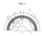
FIG. 1 is a plan view of a motor in accordance with a first embodiment of the disclosure; -
FIG. 2 is an enlarged view of the motor shown inFIG. 1 ; -
FIG. 3 is a plan view of a permanent magnet of the motor in accordance with the first embodiment; -
FIG. 4 is a plan view of a rotor core of the motor in accordance with the first embodiment; -
FIG. 5 is a plan view of a motor according to a comparative example; -
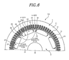
FIG. 6 is a diagram for explaining a magnetic flux generated in the motor in accordance with the first embodiment; -
FIG. 7 is a diagram showing a relationship between inductance and current of the motor according to the first embodiment and the motor according to the comparative example; -
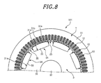
FIG. 8 is a plan view of a motor in accordance with a second embodiment of the disclosure; -
FIG. 9 is an enlarged view of the motor shown inFIG. 8 ; -
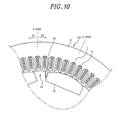
FIG. 10 is a plan view of a motor according to a modification example of the first embodiment; and -
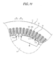
FIG. 11 is a plan view of a motor according to a modification example of the second embodiment. - Hereinafter, embodiments will be described in detail with reference to the accompanying drawings.
- First, a configuration of a
motor 100 in accordance with a first embodiment of the disclosure will be described with reference toFIGS. 1 to 4 . Themotor 100 is an example of "rotary electric machine". - As shown in
FIG. 1 , themotor 100 includes astator 1 and arotor 2. Thestator 1 is arranged so as to face an outer peripheral portion of the rotor 2 (rotor core 21). Thestator 1 also includes astator core 11 andwindings 12. At an inner side of thestator core 11, a plurality ofslots 13 are formed. - The
rotor 2 includes therotor core 21, ashaft 22, andpermanent magnets 23. In the first embodiment, therotor core 21 includes a plurality of firstmagnetic pole portions 24 having thepermanent magnets 23 and a plurality of secondmagnetic pole portions 25 having nopermanent magnets 23 which are alternately arranged one by one in a circumferential manner. Further, each of the secondmagnetic pole portions 25 is configured as a protruding portion of therotor core 21 located between twopermanent magnets 23 adjacent to each other. - As shown in
FIG. 3 , asurface 23a of each of thepermanent magnets 23 on the side of thestator core 11 is formed in a convex (arcuate) shape toward thestator core 11 when viewed from the axial direction. The radius of curvature of thesurface 23a is smaller than that of an inner peripheral portion of thestator core 11. Bothside surfaces 23b of thepermanent magnet 23 in the circumferential direction of the rotor and asurface 23c of thepermanent magnet 23 on the inner peripheral side of therotor core 21 are formed in a linear shape (flat surface shape) when viewed from the axial direction. - In the first embodiment, the
permanent magnet 23 has a shape such that a thickness t2 of the central portion in the circumferential direction is larger than a thickness (i.e., length of theside surfaces 23b in the circumferential direction of the rotor) t1 of the end portion in the circumferential direction. Further, as shown inFIGS. 1 and2 , thepermanent magnets 23 are disposed substantially equidistant in the circumferential direction. The thickness of thepermanent magnets 23 in the radial direction of the rotor is larger than a minimum interval L1 between thepermanent magnets 23 of the two firstmagnetic pole portions 24 adjacent to each other (distance on the innermost peripheral side between the two adjacent permanent magnets 23). Additionally, thepermanent magnet 23 is constituted by a ferrite permanent magnet. - In the first embodiment, the
permanent magnets 23 are embedded along the circumferential direction in the vicinity of the outer periphery of therotor core 21. More specifically, thepermanent magnets 23 are arranged on mountingportions 21a provided at the outer peripheral portion of therotor core 21. As shown inFIG. 4 , themounting portions 21a are formed in a groove shape opened on the side of thestator core 11. Thus, as shown inFIG. 2 , a portion (portion other than both end portions of the permanent magnet 23) of thesurface 23a of thepermanent magnet 23 on the side of thestator core 11 is exposed. - As shown in
FIG. 4 , each of themounting portions 21a includesside portions 21b in contact with theside surfaces 23b (seeFIG. 2 ) of thepermanent magnet 23 and having a straight line shape when viewed from the axial direction, abottom portion 21c in contact with thesurface 23c (seeFIG. 2 ) of thepermanent magnet 23 on the inner peripheral side of therotor core 21 and having a straight line shape when viewed from the axial direction. Each of themounting portions 21a further includesclaw portions 21d engaging with opposite end portions of thesurface 23a (seeFIG. 2 ) of thepermanent magnet 23 in the circumferential direction. Further, theclaw portions 21d have a function to prevent thepermanent magnet 23 from popping out of therotor core 21 when therotor core 21 is rotated. - In the first embodiment, as shown in
FIG. 2 , therotor core 21 is configured to have an average value of a gap length L2 between the secondmagnetic pole portions 25 and thestator core 11 larger than an average value of a gap length L3 between the firstmagnetic pole portions 24 and thestator core 11. Further, in the first magnetic pole portion 24 (permanent magnet 23), thesurface 23a on the side of thestator core 11 is formed in a circular arc shape having a radius of curvature smaller than that of the inner periphery of thestator core 11. Thepermanent magnet 23 is the closest to thestator core 11 in the central portion of thepermanent magnet 23 in the circumferential direction. - For example, the gap length L3 between the
stator core 11 and a portion of thepermanent magnet 23 closest thereto is about 0.4 mm. Also, the outer peripheral surface of each of the secondmagnetic pole portions 25 is configured to have a radius of curvature substantially the same as thestator core 11. Thus, the gap length L2 between thestator core 11 and the secondmagnetic pole portions 25 is substantially equal along the circumferential direction. For example, the gap length L2 between thestator core 11 and the secondmagnetic pole portions 25 is about 1 mm. - As shown in
FIGS. 1 and2 ,notches 26 are provided in portions of the secondmagnetic pole portions 25 on the side of thepermanent magnets 23. Thenotches 26 are formed so as to extend in the axial direction (perpendicular to the paper surface) of therotor core 21. In addition, thenotches 26 are provided in each of the secondmagnetic pole portions 25. As shown inFIG. 2 , thenotches 26 include anotch 26a which is provided in a portion of the secondmagnetic pole portion 25 adjacent to thepermanent magnet 23 in one circumferential direction (direction of arrow R1), and anotch 26b which is provided at a portion of the secondmagnetic pole portion 25 adjacent to thepermanent magnet 23 in the other circumferential direction (direction of arrow R2). - In the
rotor core 21, a thickness L4 (seeFIG. 2 ) of aportion 21e located between thenotch 26a and theside surface 23b of thepermanent magnet 23 adjacent to thenotch 26a is smaller than a width L5 (length in the direction perpendicular to the radial direction) (seeFIG. 2 ) of the secondmagnetic pole portion 25 between thenotches rotor core 21, a thickness L6 (seeFIG. 2 ) of aportion 21f located between thenotch 26b and theside surface 23b of thepermanent magnet 23 adjacent to thenotch 26b is smaller than the width L5 (length in the direction perpendicular to the radial direction) (seeFIG. 2 ) of the secondmagnetic pole portion 25 between thenotches portion 21e (21f) of therotor core 21 is substantially equal to a length L7 of theclaw portions 21d of therotor core 21 in the radial direction. - Each of the
notches 26 is formed in a substantially V shape such that a width W1 of thenotch 26 is gradually reduced toward the inner peripheral side of therotor core 21 when viewed from the axial direction. Thebottom end 26c of thenotch 26 on the inner peripheral side of therotor core 21 is located radially outward of thebottom end 23d of theside surface 23b of thepermanent magnet 23 on the inner peripheral side of therotor core 21. Further, thebottom end 26c of thenotch 26 may be located radially at a same position as that of thebottom end 23d of thepermanent magnet 23 in therotor core 21. In addition, thebottom end 26c of thenotch 26 is located radially inward of a midpoint (point A) of theside surface 23b of thepermanent magnet 23 in a thickness direction thereof. - A
surface 26d (26e) of thenotch 26, i.e., thenotch 26a (26b), opposite to thepermanent magnets 23 is disposed in a direction along the q-axis of themotor 100. That is, theinner surface 26d of thenotch 26a and theinner surface 26e of thenotch 26b are disposed to be substantially parallel to the q-axis. Further, the q-axis means an axis in a direction electrically perpendicular to the d-axis which is in a direction of a main magnetic flux. Further, aninner surface 26f (inner surface 26g) of thenotch 26 on the side of thepermanent magnet 23 is arranged in a direction (direction intersecting the q-axis) substantially parallel to theside surface 23b of thepermanent magnet 23. - Next, with reference to
FIGS. 5 to 7 , a relationship between inductance and current supplied to thewindings 12 of themotor 100 in accordance with the first embodiment will be described in comparison with a comparative example shown inFIG. 5 . - As shown in
FIG. 5 , twopermanent magnets motor 200 according to the comparative example. In themotor 200 according to the comparative example, unlike themotor 100 of the first embodiment, arotor core 221 is configured such that an average value of a gap length L8 between astator core 211 and a secondmagnetic pole portion 225 is equal to an average value of a gap length L9 between thestator core 211 and a firstmagnetic pole portion 224. - In the
motor 200 according to the comparative example, magnetic flux due to the d-axis current is generated to pass through thepermanent magnets rotor core 221. Further, magnetic flux caused by the q-axis current is generated to respectively pass along the inside and outside of the V-shaped arrangement of thepermanent magnets rotor core 221. - Contrastingly, in the
motor 100 of the first embodiment, as shown inFIG. 6 , the magnetic flux due to the d-axis current is generated to pass through the two adjacentpermanent magnets 23 in therotor core 21. In addition, the magnetic flux due to the q-axis current is generated to pass around thepermanent magnet 23 in the inner peripheral side of therotor core 21. In themotor 100, since thepermanent magnets 23 are embedded in the vicinity of the outer periphery of therotor core 21, the magnetic flux due to the q-axis current is suppressed from occurring in a portion of therotor core 21 located radially outward of thepermanent magnets 23. Referring toFIGS. 2 and6 , the thickness of thepermanent magnets 23 in the direction of the d-axis magnetic flux passing through thepermanent magnets 23 is larger than the minimum interval L1 between two adjacentpermanent magnets 23. - As shown in
FIG. 7 , in themotor 200 according to the comparative example, when current flowing throughwindings 212 is relatively small (about 20 A - about 80 A) (low load), the q-axis inductance Lq is relatively large (about 0.5 mH - about 0.55 mH). Therefore, in themotor 200 according to the comparative example, in the case of high-speed rotation, an output of themotor 200 is limited by voltage saturation (state where magnitude of a voltage required to obtain a desired torque from themotor 200 exceeds a voltage limit value). - In the
motor 200 according to the comparative example, when the current flowing through thewindings 212 is relatively large (about 200 A - about 320 A) (high load), the q-axis inductance Lq is sharply decreased compared to the case of the low load. It is considered that this is because in themotor 200 according to the comparative example, twopermanent magnets rotor core 221 is saturated on the inside and outside of the V-shaped arrangement of thepermanent magnets motor 200 according to the comparative example, the d-axis inductance Ld decreases gradually as the current flowing through thewindings 212 increases and then becomes substantially constant in the case of the low load. - In the
motor 100 according to the first embodiment, when the current flowing through thewindings 12 is relatively small (about 20 A - about 80 A) (low load), the q-axis inductance Lq is about 0.35 mH - about 0.4 mH, and is smaller than the q-axis inductance Lq (about 0.5 mH - about 0.55 mH) of themotor 200 according to the comparative example. This is considered to be due to the following reasons. - In the first embodiment, the
rotor core 21 is configured such that the average value of the gap length L2 between thestator core 11 and the secondmagnetic pole portions 25 is larger than that of the gap length L3 between thestator core 11 and the firstmagnetic pole portions 24. Accordingly, the magnetic flux caused by the q-axis current is difficult to pass through a space (air) between thestator core 11 and the secondmagnetic pole portions 25 compared to the case of the comparative example. As a result, the q-axis inductance Lq in the case of the first embodiment is smaller than that of the comparative example. - In addition, the
permanent magnets 23 are arranged in the vicinity of the outer periphery of therotor core 21, so that, unlike theconventional motor 200, the q-axis inductance Lq is suppressed from occurring in the outer peripheral side of thepermanent magnets 23, and the q-axis inductance Lq is reduced correspondingly. Meanwhile, in the first embodiment, while the q-axis inductance Lq is reduced at the high load compared with at the low load, the reduction degree of the q-axis inductance Lq is lower as compared to theconventional motor 200. - Further, in the
motor 100 according to the first embodiment, the d-axis inductance Ld decreases gradually as the current flowing through thewindings 12 increases, and is then substantially constant. The d-axis inductance Ld of themotor 100 according to the first embodiment is smaller than that of the d-axis inductance Ld of themotor 200 according to the comparative example. This is considered to be due to the following reasons. That is, since a thickness t2 of thepermanent magnets 23 corresponds to about twice the thickness of thepermanent magnets motor 200 according to the comparative example, the magnetic flux due to the d-axis current is difficult to pass through the d-axis path. As a result, it is considered that the d-axis inductance Ld becomes smaller. - In addition, when the current flowing through the windings 12 (windings 212) is relatively large (about 200 A - about 320 A) (high load), a difference between the d-axis inductance Ld and the q-axis inductance Lq of the
motor 100 according to the first embodiment is larger than a difference between the d-axis inductance Ld and the q-axis inductance Lq of themotor 200 according to the comparative example. That is, in themotor 100 according to the first embodiment, it is possible to obtain a reluctance torque greater than that of themotor 200 according to the comparative example. - In the first embodiment, as described above, the
rotor core 21 is configured such that the average value of the gap length L2 between thestator core 11 and the secondmagnetic pole portions 25 is larger than that of the gap length L3 between thestator core 11 and the firstmagnetic pole portions 24. Accordingly, the magnetic flux (magnetic flux due to the q-axis current) becomes difficult to pass through a space (air) between thestator core 11 and the secondmagnetic pole portions 25 by an increase in the average value of the gap length L2 between the secondmagnetic pole portions 25 and thestator core 11. As a result, it is possible to reduce the q-axis inductance Lq at a low load. Furthermore, since the occurrence of voltage saturation is suppressed due to the fact that there is less increase in impedance due to inductance components of the d and q axes (q-axis in particular) at the time of high-speed rotation, it is possible to obtain a predetermined output. - In the first embodiment, as described above, the
permanent magnets 23 are embedded in the vicinity of the outer periphery of therotor core 21. That is, a length of thepermanent magnets 23 in the circumferential direction of therotor core 21 is larger than a length (i.e., a thickness of the permanent magnets 23) in the radial direction of the rotor. Thus, since the magnetic flux due to the q-axis current is suppressed from occurring at the portion of therotor core 21 on the outer peripheral side of thepermanent magnets 23, it is possible to further reduce the q-axis inductance Lq. - In the first embodiment, as described above, the
permanent magnets 23 are embedded along the circumferential direction in the vicinity of the outer periphery of therotor core 21. As in the motor 200 (seeFIG. 5 ) according to the comparative example, when the twopermanent magnets permanent magnets rotor core 221. - Accordingly, permeance (reciprocal of magnetic resistance) of the permanent magnets is reduced and demagnetization is likely to occur. In contrast, by embedding the
permanent magnets 23 along the circumferential direction in the vicinity of the outer periphery of therotor core 21 in the first embodiment, it is possible to increase the minimum interval between the adjacentpermanent magnets 23. Thus, it is possible to increase the permeance (reciprocal of the magnetic resistance) of thepermanent magnets 23, and suppress thepermanent magnets 23 from being easily demagnetized. - In the motor 200 (see
FIG. 5 ) according to the comparative example in which the twopermanent magnets permanent magnets permanent magnets permanent magnets rotor core 21. As a result, in the first embodiment in which thepermanent magnets 23 are embedded along the circumferential direction in the vicinity of the outer periphery of therotor core 21, it is possible to easily perform the magnetization on thepermanent magnets 23 after arranging thepermanent magnets 23 in therotor core 21. - In the first embodiment, as described above, the
permanent magnets 23 are configured to have a shape such that the thickness t2 of the central portion in the circumferential direction is larger than the thickness t1 of the end portion in the circumferential direction. Thus, since the magnetic flux due to the d-axis current becomes difficult to pass through thepermanent magnet 23, it is possible to reduce the d-axis inductance Ld. As a result, it is possible to obtain a larger reluctance torque by increasing a difference (Ld-Lq) between the d-axis inductance (Ld) and the q-axis inductance (Lq). - Additionally, in the first embodiment, as described above, the
permanent magnets 23 are configured to have the thickness t1 (t2) larger than the minimum interval L1 between two adjacentpermanent magnets 23. Therefore, it is possible to effectively reduce the d-axis inductance Ld. - In the first embodiment, as described above, the
permanent magnets 23 are arranged in the vicinity of the outer periphery of therotor core 21 to expose at least a portion of thesurface 23a of each of thepermanent magnets 23 on the side of thestator core 11. Accordingly, therotor core 21 is configured such that the average value of the gap length L2 between thestator core 11 and the secondmagnetic pole portions 25 is larger than the average value of the gap length L3 for thestator core 11 in the firstmagnetic pole portions 24. Thus, since it is possible to make the exposed portions of thepermanent magnets 23 closer to thestator core 11, it is possible to further increase magnetic torque. - Further, in the first embodiment, as described above, the
permanent magnets 23 are formed of ferrite permanent magnets. The ferrite magnets have a weak magnetic force compared to rare earth magnets. In accordance with embodiments disclosed herein, since the reluctance torque is effectively available, it is possible to easily obtain a desired output even in case of using the ferrite permanent magnets. - Next, a
motor 101 of a second embodiment will be described with reference toFIGS. 8 and9 . Unlike the first embodiment in which thesurface 23a of each of thepermanent magnets 23 on the side of thestator core 11 is exposed, themotor 101 of the second embodiment is embedded in arotor core 31 such that asurface 33a of each ofpermanent magnets 33 on the side of thestator core 11 is not exposed. Themotor 101 is an example of "rotary electric machine" in accordance with embodiments disclosed herein. - As shown in
FIG. 8 , a rotor 3 of themotor 101 in accordance with the second embodiment includes arotor core 31, ashaft 32, and thepermanent magnets 33. In therotor core 31, a plurality of firstmagnetic pole portions 34 havingpermanent magnets 33 and a plurality of secondmagnetic pole portions 35 having nopermanent magnets 33 are alternately arranged one by one in a circumferential manner. Further, thepermanent magnets 33 are embedded along the circumferential direction in the vicinity of the outer periphery of therotor core 31 such that thesurface 33a of each of thepermanent magnets 33 on the side of thestator core 11 is not exposed. Specifically, thepermanent magnets 33 are embedded in mountingportions 31a formed in a hole shape to cover the outer periphery of thepermanent magnets 33. - In the second embodiment, as shown in
FIG. 9 , therotor core 31 is configured such that an average value of a gap length L10 (e.g., about 1 mm) between thestator core 11 and the secondmagnetic pole portions 35 is larger than that of a gap length L11 (e.g., about 0.4 mm) between thestator core 11 and the firstmagnetic pole portions 34. That is, the outer peripheral surface of therotor core 31 in the secondmagnetic pole portions 35 is disposed more inward than the outer peripheral surface of therotor core 31 in the firstmagnetic pole portions 34. - The
surface 33a of each of thepermanent magnets 33 on the side of thestator core 11 and an outerperipheral portion 31b of each of the firstmagnetic pole portions 34 of therotor core 31 are configured to have substantially the same radius of curvature as that of the inner periphery of thestator core 11. Thus, the gap length L11 (e.g., about 0.4 mm) between thestator core 11 and the firstmagnetic pole portions 34 is substantially equal along the circumferential direction. Also, the outer periphery of the secondmagnetic pole portions 35 is configured to have substantially the same radius of curvature as that of the rotor core 31 (stator core 11). Thus, the gap length L10 (about 1 mm) between thestator core 11 and the secondmagnetic pole portions 35 is substantially equal along the circumferential direction. - As shown in
FIGS. 8 and9 ,notches 36 are provided in portions of the secondmagnetic pole portions 35 on the side of thepermanent magnets 33. Thenotches 36 includenotches notch 36a is provided at a portion of the secondmagnetic pole portion 35 adjacent to thepermanent magnet 33 on one side (direction of arrow R1) of the circumferential direction. Thenotch 36b is provided at a portion of the secondmagnetic pole portion 35 adjacent to thepermanent magnet 33 on the other side (direction of arrow R2) of the circumferential direction. - Each of the
notches 36 is formed in a substantially V shape such that a width W1 of thenotch 36 is gradually reduced toward the inner peripheral side of therotor core 31 when viewed from the axial direction. Additionally, thebottom end 36c of thenotch 36 on the inner peripheral side of therotor core 31 is located radially outward of thebottom end 33c of theside surface 33b of thepermanent magnet 33 on the inner peripheral side of the rotor core 31 (and a midpoint (point B) of theside surface 33b of thepermanent magnet 33 in the thickness direction thereof). The remaining configuration of the second embodiment is the same as the first embodiment. - In the second embodiment, as described above, the
permanent magnets 33 are embedded in the vicinity of the outer periphery of therotor core 31 such that thesurface 33a of each of thepermanent magnets 33 on the side of thestator core 11 is not exposed. Further, therotor core 31 is configured such that the average gap length L10 between thestator core 11 and the secondmagnetic pole portions 35 is larger than the average gap length L11 between thestator core 11 and the firstmagnetic pole portions 34. Thus, since thesurface 33a of each of thepermanent magnets 33 on the side of thestator core 11 is covered with therotor core 31, it is possible to effectively suppress thepermanent magnets 33 from popping out toward thestator core 11. - In addition, other effects of the second embodiment are the same as those of the first embodiment.
- It should be considered that the embodiments disclosed herein are illustrative in all respects and not restrictive. The scope of the present invention is indicated by the appended claims rather than the foregoing description of the embodiments, and includes the equivalent of the claims and all modifications within the scope thereof.
- For example, in the first and second embodiments, the motor has been described as an example of the rotary electric machine, but the disclosed embodiments are not limited thereto. For example, the disclosed embodiments may be applied to a generator serving as another example of the rotary electric machine. Further, the disclosed embodiments are applicable to a vehicle, ship or the like.
- Also, in the first embodiment, a case where only the gap length between the stator core and the permanent magnets (first magnetic pole portions) varies along the circumferential direction has been described, but the disclosed embodiments are not limited thereto. For example, only the gap length between the stator core and the second magnetic pole portions may be varied along the circumferential direction, and the gap lengths between the stator core and both the first magnetic pole portions and the second magnetic pole portions may be varied along the circumferential direction.
- Additionally, in the first and second embodiments, a case where the permanent magnets have a shape such that the thickness of the central portion in the circumferential direction is larger than the thickness of the end portion in the circumferential direction has been described, but the permanent magnets may have another shape. For example, the permanent magnets may have a rectangular shape or an arcuate shape having the same thickness in the circumferential direction.
- Further, in the first and second embodiments, a case where the permanent magnets are formed of ferrite permanent magnets has been described, but the present invention is not limited thereto. For example, the permanent magnets may be made of a material containing rare earths such as neodymium.
- In the first embodiment, there has been described a case where the permanent magnets are arranged in the vicinity of the outer periphery of the rotor core to expose at least a portion (portion other than both end portions) of the surface of the permanent magnet on the side of the stator core, but the present invention is not limited thereto. For example, the permanent magnets may be arranged in the vicinity of the outer periphery of the rotor core to expose all the surface of the permanent magnet on the side of the stator core.
- Also, in the first and second embodiments, there have been described cases where the gap length of a portion of the permanent magnet closest to the stator core is about 0.4 mm and the average gap length L2 between the rotor core and the second magnetic pole portions is about 1 mm has been described, and where the average gap length between the stator core and the first magnetic pole portions is about 0.4 mm and the average gap length L2 between the rotor core and the second magnetic pole portions is about 1 mm, respectively. However, values of the gap lengths are not limited thereto. For example, if the rotor core is configured such that the average gap length between the stator core and the second magnetic pole portions is larger than the average gap length between the stator core and the first magnetic pole portions, each of the gap lengths may have a value other than about 1 mm and about 0.4 mm.
- Additionally, in the first and second embodiments, a case where two notches are provided in each of the second magnetic pole portions has been described, but the number of the notches is not limited thereto. For example, as shown in a modification example of the first embodiment illustrated in
FIG. 10 , onenotch 42 may be provided at one side portion of the secondmagnetic pole portion 41 on the side of the permanent magnet 33 (e.g., direction of arrow R2). - That is, second
magnetic pole portions 41 may be formed in a shape asymmetrical about the q-axis of themotor 102. Accordingly, unlike the case where the second magnetic pole portions are formed in a shape symmetrical about the q-axis, it is possible to vary the motor characteristics depending on the direction of rotation by changing the saturation of the magnetic flux of the q-axis differently from the symmetric case. Themotor 102 is also an example of "rotary electric machine" in accordance with the disclosed embodiments. - Also, in the first and second embodiments, a case where the permanent magnets are formed such that their surfaces on the side of the stator core have a cross-sectional shape of an arcuate shape has been described, but the cross-sectional shape of the permanent magnets is not limited thereto. For example, the permanent magnets may be formed to have a substantially rectangular cross-sectional shape.
- In the second embodiment, a case where an interval between the
stator core 11 and thesurface 33a of thepermanent magnet 33 is larger than the gap length L10 between thestator core 11 and the secondmagnetic pole portions 35 has been shown inFIG. 9 , but the present invention is not limited thereto. For example, as shown in a modification example of the second embodiment illustrated inFIG. 11 , it may be configured such that an interval L13 between thestator core 11 and thesurface 33a of thepermanent magnet 33 is smaller than a gap length L12 between thestator core 11 and the secondmagnetic pole portions 35.
Claims (10)
- A rotary electric machine comprising:a rotor core in which first magnetic pole portions having permanent magnets and second magnetic pole portions having no permanent magnets are alternately arranged in a circumferential direction; anda stator core which is arranged to face an outer periphery of the rotor core,wherein the rotor core is configured such that an average gap length between the stator core and the second magnetic pole portions is larger than an average gap length between the stator core and the first magnetic pole portions.
- The rotary electric machine of claim 1, wherein a thickness of each of the permanent magnets in a direction of a d-axis magnetic flux passing therethrough is larger than a minimum interval between the permanent magnets of adjacent two of the first magnetic pole portions.
- The rotary electric machine of claim 1 or 2, wherein a thickness of the permanent magnets in a radial direction of the rotor core is larger than a minimum interval between the permanent magnets of adjacent two of first magnetic pole portions.
- The rotary electric machine of any one of claims 1 to 3, wherein the permanent magnets are embedded in the vicinity of the outer periphery of the rotor core.
- The rotary electric machine of claim 4, wherein the permanent magnets are embedded in the vicinity of the outer periphery of the rotor core along the circumferential direction.
- The rotary electric machine of any one of claims 1 to 5, wherein each of the permanent magnets has a shape such that a thickness of a circumferential central portion is larger than a thickness of circumferentially opposite end portions thereof.
- The rotary electric machine of any one of claims 1 to 6, wherein the permanent magnets are embedded in the vicinity of the outer periphery of the rotor core to expose at least a portion of a surface of the permanent magnet facing the stator core.
- The rotary electric machine of any one of claims 1 to 6, wherein the permanent magnets are embedded in the vicinity of the outer periphery of the rotor core not to expose a surface of the permanent magnet facing the stator core.
- The rotary electric machine of any one of claims 1, to 8, wherein each of the permanent magnets is formed of a ferrite permanent magnet.
- The rotary electric machine of any one of claims 1 to 9, wherein each of the second magnetic pole portions has at least one notch provided near the permanent magnet adjacent thereto.
Applications Claiming Priority (1)
| Application Number | Priority Date | Filing Date | Title |
|---|---|---|---|
| JP2012028195A JP5594303B2 (en) | 2012-02-13 | 2012-02-13 | Rotating electric machine |
Publications (1)
| Publication Number | Publication Date |
|---|---|
| EP2626976A2 true EP2626976A2 (en) | 2013-08-14 |
Family
ID=47559320
Family Applications (1)
| Application Number | Title | Priority Date | Filing Date |
|---|---|---|---|
| EP13151559.5A Withdrawn EP2626976A2 (en) | 2012-02-13 | 2013-01-17 | Rotary electric machine |
Country Status (5)
| Country | Link |
|---|---|
| US (1) | US9041268B2 (en) |
| EP (1) | EP2626976A2 (en) |
| JP (1) | JP5594303B2 (en) |
| KR (1) | KR101481882B1 (en) |
| CN (1) | CN103248188A (en) |
Families Citing this family (10)
| Publication number | Priority date | Publication date | Assignee | Title |
|---|---|---|---|---|
| US10153671B2 (en) * | 2011-12-29 | 2018-12-11 | Philip Totaro | Permanent magnet rotor with intrusion |
| US10164488B2 (en) * | 2014-07-31 | 2018-12-25 | Steering Solutions Ip Holding Corporation | Brushless motor having a permanent magnet rotor |
| WO2016024325A1 (en) * | 2014-08-11 | 2016-02-18 | 富士電機株式会社 | Dynamo-electric machine |
| CN106030989B (en) * | 2014-08-11 | 2018-09-11 | 富士电机株式会社 | Electric rotating machine |
| US10594178B2 (en) * | 2015-09-08 | 2020-03-17 | Lg Electronics Inc. | Rotor and motor including the same |
| CN107196478B (en) * | 2017-06-21 | 2023-07-04 | 珠海格力节能环保制冷技术研究中心有限公司 | permanent magnet motor |
| KR102589674B1 (en) * | 2018-01-31 | 2023-10-16 | 엘지이노텍 주식회사 | Rotor and motor having the same |
| CN111869067B (en) * | 2018-03-27 | 2023-05-09 | 株式会社电装 | Motor with a motor housing having a motor housing with a motor housing |
| JP7478104B2 (en) * | 2021-01-08 | 2024-05-02 | 株式会社アイシン | Rotor core |
| DE102021214616A1 (en) * | 2021-12-17 | 2023-06-22 | Robert Bosch Gesellschaft mit beschränkter Haftung | Rotor for an electric motor and electric motor with a rotor |
Citations (1)
| Publication number | Priority date | Publication date | Assignee | Title |
|---|---|---|---|---|
| JPH01286758A (en) | 1988-05-13 | 1989-11-17 | Hitachi Ltd | Permanent magnet type synchronous motor |
Family Cites Families (13)
| Publication number | Priority date | Publication date | Assignee | Title |
|---|---|---|---|---|
| JP3142002B2 (en) * | 1990-07-12 | 2001-03-07 | セイコーエプソン株式会社 | Permanent magnet rotor |
| JP3678517B2 (en) * | 1996-11-19 | 2005-08-03 | 日機装株式会社 | Radial force generator, coiled rotating machine, and rotating device |
| JP2002262533A (en) * | 2001-02-28 | 2002-09-13 | Hitachi Ltd | Permanent magnet type rotating electric machine |
| JP2002305859A (en) | 2001-03-30 | 2002-10-18 | Aisin Aw Co Ltd | Permanent magnet type synchronous motor |
| JP2004032947A (en) * | 2002-06-27 | 2004-01-29 | Aisin Aw Co Ltd | Motor |
| JP4065829B2 (en) * | 2003-10-10 | 2008-03-26 | 本田技研工業株式会社 | Permanent magnet rotor and brushless motor |
| US7898137B2 (en) * | 2006-08-30 | 2011-03-01 | Shin-Etsu Chemical Co., Ltd. | Permanent magnet and permanent magnet rotating machine |
| JP5082534B2 (en) * | 2007-03-27 | 2012-11-28 | 株式会社安川電機 | Surface permanent magnet synchronous machine |
| EP3540915B1 (en) * | 2007-11-15 | 2022-05-11 | Mitsubishi Electric Corporation | Permanent magnet type rotating electrical machine and electric power steering device |
| JP4740273B2 (en) * | 2008-03-04 | 2011-08-03 | 日立オートモティブシステムズ株式会社 | Rotating electric machine and hybrid vehicle using the same |
| JP5385077B2 (en) * | 2009-10-02 | 2014-01-08 | アスモ株式会社 | Rotating motor |
| CN102035269B (en) | 2009-10-07 | 2014-10-15 | 阿斯莫有限公司 | Motor |
| JP5513059B2 (en) * | 2009-10-07 | 2014-06-04 | アスモ株式会社 | Rotor and motor |
-
2012
- 2012-02-13 JP JP2012028195A patent/JP5594303B2/en active Active
-
2013
- 2013-01-17 EP EP13151559.5A patent/EP2626976A2/en not_active Withdrawn
- 2013-02-08 CN CN2013100508264A patent/CN103248188A/en active Pending
- 2013-02-13 KR KR20130015113A patent/KR101481882B1/en not_active Expired - Fee Related
- 2013-02-13 US US13/765,718 patent/US9041268B2/en not_active Expired - Fee Related
Patent Citations (1)
| Publication number | Priority date | Publication date | Assignee | Title |
|---|---|---|---|---|
| JPH01286758A (en) | 1988-05-13 | 1989-11-17 | Hitachi Ltd | Permanent magnet type synchronous motor |
Also Published As
| Publication number | Publication date |
|---|---|
| KR101481882B1 (en) | 2015-01-13 |
| JP5594303B2 (en) | 2014-09-24 |
| CN103248188A (en) | 2013-08-14 |
| US20130207508A1 (en) | 2013-08-15 |
| JP2013165601A (en) | 2013-08-22 |
| US9041268B2 (en) | 2015-05-26 |
| KR20130093040A (en) | 2013-08-21 |
Similar Documents
| Publication | Publication Date | Title |
|---|---|---|
| US9041268B2 (en) | Rotary electric machine | |
| CN108075585B (en) | Rotating electrical machine | |
| KR101880377B1 (en) | Interior permanent magnet rotating electric machine | |
| CN103986259B (en) | The rotor of electric rotating machine | |
| EP2712058B1 (en) | Permanent-magnet type rotating electrical machine | |
| US10033234B2 (en) | Motor | |
| US9276443B2 (en) | Rotating element with embedded permanent magnet and rotating electrical machine | |
| US9337692B2 (en) | Permanent magnet rotor with flux barrier for reduced demagnetization | |
| CN108777520B (en) | Alternating-pole motor | |
| CN111052546B (en) | Rotor of rotating electric machine | |
| US12261485B2 (en) | Rotor with permanent magnets having different coercive forces | |
| KR101473086B1 (en) | Rotary electric machine | |
| JP2017050965A (en) | Rotor structure of rotating electrical machine | |
| JP6507956B2 (en) | Permanent magnet type rotating electric machine | |
| CN105164897B (en) | Permanent magnet motor | |
| JP6428458B2 (en) | Embedded magnet type motor | |
| EP3098942B1 (en) | Rotor | |
| JP6451517B2 (en) | Rotor | |
| EP3273581A1 (en) | Rotor of permanent magnet motor | |
| KR20250154452A (en) | Rotor core, rotor, rotating electric machine and method of designing rotor core |
Legal Events
| Date | Code | Title | Description |
|---|---|---|---|
| PUAI | Public reference made under article 153(3) epc to a published international application that has entered the european phase |
Free format text: ORIGINAL CODE: 0009012 |
|
| AK | Designated contracting states |
Kind code of ref document: A2 Designated state(s): AL AT BE BG CH CY CZ DE DK EE ES FI FR GB GR HR HU IE IS IT LI LT LU LV MC MK MT NL NO PL PT RO RS SE SI SK SM TR |
|
| AX | Request for extension of the european patent |
Extension state: BA ME |
|
| STAA | Information on the status of an ep patent application or granted ep patent |
Free format text: STATUS: THE APPLICATION HAS BEEN WITHDRAWN |
|
| 18W | Application withdrawn |
Effective date: 20150421 |