EP2626968A2 - Solar inverter system and control method thereof - Google Patents
Solar inverter system and control method thereof Download PDFInfo
- Publication number
- EP2626968A2 EP2626968A2 EP13153576.7A EP13153576A EP2626968A2 EP 2626968 A2 EP2626968 A2 EP 2626968A2 EP 13153576 A EP13153576 A EP 13153576A EP 2626968 A2 EP2626968 A2 EP 2626968A2
- Authority
- EP
- European Patent Office
- Prior art keywords
- inverter
- output power
- solar
- total
- controller
- Prior art date
- Legal status (The legal status is an assumption and is not a legal conclusion. Google has not performed a legal analysis and makes no representation as to the accuracy of the status listed.)
- Withdrawn
Links
Images


Classifications
-
- H—ELECTRICITY
- H02—GENERATION; CONVERSION OR DISTRIBUTION OF ELECTRIC POWER
- H02J—ELECTRIC POWER NETWORKS; CIRCUIT ARRANGEMENTS OR SYSTEMS FOR SUPPLYING OR DISTRIBUTING ELECTRIC POWER; SYSTEMS FOR STORING ELECTRIC ENERGY
- H02J3/00—Circuit arrangements for AC mains or AC distribution networks
- H02J3/38—Arrangements for feeding a single network from two or more generators or sources in parallel; Arrangements for feeding already energised networks from additional generators or sources in parallel
- H02J3/46—Controlling the sharing of generated power between the generators, sources or networks
- H02J3/466—Scheduling or selectively controlling the operation of the generators or sources, e.g. connecting or disconnecting generators to meet a demand
- H02J3/472—Scheduling or selectively controlling the operation of the generators or sources, e.g. connecting or disconnecting generators to meet a demand for selectively connecting the AC sources in a particular order, e.g. sequential, alternating or subsets of sources
-
- H—ELECTRICITY
- H02—GENERATION; CONVERSION OR DISTRIBUTION OF ELECTRIC POWER
- H02J—ELECTRIC POWER NETWORKS; CIRCUIT ARRANGEMENTS OR SYSTEMS FOR SUPPLYING OR DISTRIBUTING ELECTRIC POWER; SYSTEMS FOR STORING ELECTRIC ENERGY
- H02J3/00—Circuit arrangements for AC mains or AC distribution networks
- H02J3/38—Arrangements for feeding a single network from two or more generators or sources in parallel; Arrangements for feeding already energised networks from additional generators or sources in parallel
- H02J3/381—Dispersed generators
-
- H—ELECTRICITY
- H02—GENERATION; CONVERSION OR DISTRIBUTION OF ELECTRIC POWER
- H02M—APPARATUS FOR CONVERSION BETWEEN AC AND AC, BETWEEN AC AND DC, OR BETWEEN DC AND DC, AND FOR USE WITH MAINS OR SIMILAR POWER SUPPLY SYSTEMS; CONVERSION OF DC OR AC INPUT POWER INTO SURGE OUTPUT POWER; CONTROL OR REGULATION THEREOF
- H02M7/00—Conversion of AC power input into DC power output; Conversion of DC power input into AC power output
- H02M7/42—Conversion of DC power input into AC power output without possibility of reversal
-
- H—ELECTRICITY
- H02—GENERATION; CONVERSION OR DISTRIBUTION OF ELECTRIC POWER
- H02J—ELECTRIC POWER NETWORKS; CIRCUIT ARRANGEMENTS OR SYSTEMS FOR SUPPLYING OR DISTRIBUTING ELECTRIC POWER; SYSTEMS FOR STORING ELECTRIC ENERGY
- H02J2101/00—Supply or distribution of decentralised, dispersed or local electric power generation
- H02J2101/20—Dispersed power generation using renewable energy sources
- H02J2101/22—Solar energy
- H02J2101/24—Photovoltaics
-
- Y—GENERAL TAGGING OF NEW TECHNOLOGICAL DEVELOPMENTS; GENERAL TAGGING OF CROSS-SECTIONAL TECHNOLOGIES SPANNING OVER SEVERAL SECTIONS OF THE IPC; TECHNICAL SUBJECTS COVERED BY FORMER USPC CROSS-REFERENCE ART COLLECTIONS [XRACs] AND DIGESTS
- Y02—TECHNOLOGIES OR APPLICATIONS FOR MITIGATION OR ADAPTATION AGAINST CLIMATE CHANGE
- Y02E—REDUCTION OF GREENHOUSE GAS [GHG] EMISSIONS, RELATED TO ENERGY GENERATION, TRANSMISSION OR DISTRIBUTION
- Y02E10/00—Energy generation through renewable energy sources
- Y02E10/50—Photovoltaic [PV] energy
- Y02E10/56—Power conversion systems, e.g. maximum power point trackers
Definitions
- the present invention relates to a solar inverter system and a control method thereof according to the pre-characterizing clauses of claims 1 and 8.
- the efficiency and the harmonic distortion of the solar inverter system with multi-inverters are usually worse than a solar inverter system with an inverter because each inverter of the solar inverter system with multi-inverters outputs the same power.
- the present invention aims at providing a solar inverter system and a control method thereof that can utilize a controller to control output power of inverters included in the solar inverter system to increase efficiency of the solar inverter system, decrease harmonic distortion of the solar inverter system, and extend service life of the inverters included in the solar inverter system.
- the claimed solar inverter system includes a first inverter, a second inverter, and a controller.
- the first inverter has a first input terminal, and a first output terminal. The first input terminal is coupled to a solar panel.
- the second inverter has a second input terminal, and a second output terminal. The second input terminal is coupled to the solar panel.
- the first output terminal and the second output terminal are parallel with a utility grid.
- the controller is coupled to the first inverter and the second inverter for controlling the first inverter and the second inverter to output total output power in turn, or controlling the first inverter and the second inverter to output the total output power simultaneously.
- FIG. 1 is a diagram illustrating a solar inverter system 100 according to an embodiment.
- the solar inverter system 100 includes a first inverter 102, a second inverter 104, and a controller 106, where the first inverter 102 is the same as the second inverter 104.
- the first inverter 102 can also be different from the second inverter 104.
- the present invention is not limited to the solar inverter system 100 only including the first inverter 102 and the second inverter 104. Therefore, the solar inverter system 100 can include at least two inverters.
- the first inverter 102 has a first input terminal and a first output terminal, where the first input terminal is coupled to a solar panel 108; the second inverter 104 has a second input terminal and a second output terminal, where the second input terminal is coupled to the solar panel 108.
- the first output terminal of the first inverter 102 and the second output terminal of the second inverter 104 are in parallel with a utility grid 112 through a sensor 110, where the sensor 110 is used for sensing an alternating current (AC) current IAC and an AC voltage VAC generated by the first inverter 102 and the second inverter 104 converting a direct current voltage VDC of the solar panel 108.
- AC alternating current
- the utility grid 112 has an AC frequency (e.g. 50Hz or 60Hz) and an AC voltage (e.g. 110V or 220V).
- the controller 106 is coupled to the first inverter 102, the second inverter 104, and the sensor 110 for calculating total output power of the solar inverter system 100 according to the AC current IAC and the AC voltage VAC, and optionally controlling the first inverter 102 and the second inverter 104 to output the total output power of the solar inverter system 100 in turn, or controlling the first inverter 102 and the second inverter 104 to output the total output power of the solar inverter system 100 simultaneously.
- the controller 106 controls the first inverter 102 and the second inverter 104 to output the total output power of the solar inverter system 100 in turn; when the total output power of the solar inverter system 100 is greater than the threshold value, the controller 106 controls the first inverter 102 and the second inverter 104 to output the total output power of the solar inverter system 100 simultaneously, and the first inverter 102 and the second inverter 104 output the maximum output power of the first inverter 102 in turn.
- a threshold value maximum output power of the first inverter 102
- output power of the second inverter 104 is the total output power of the solar inverter system 100 minus the maximum output power of the first inverter 102; and when the total output power of the solar inverter system 100 is greater than the threshold value and the output power of the second inverter 104 is the maximum output power of the first inverter 102, the output power of the first inverter 102 is the total output power of the solar inverter system 100 minus the maximum output power of the first inverter 102.
- the maximum output power of the first inverter 102 is 120W.
- the controller 106 controls the first inverter 102 and the second inverter 104 to output the total output power (110W) of the solar inverter system 100 in turn because the total output power (110W) of the solar inverter system 100 is less than the threshold value (120W).
- the controller 106 controls the first inverter 102 and the second inverter 104 to output the total output power (130W) of the solar inverter system 100 simultaneously, and the first inverter 102 and the second inverter 104 output the maximum output power (120W) of the first inverter 102 in turn.
- the output power of the second inverter 104 is the total output power (130W) of the solar inverter system 100 minus the maximum output power (120W) of the first inverter 102. Therefore, the output power of the second inverter 104 is 10W.
- the output power of the first inverter 102 is the total output power (130W) of the solar inverter system 100 minus the maximum output power (120W) of the first inverter 102. Therefore, the output power of the first inverter 102 is 10W.
- the solar inverter system 100 further includes the sensor 110.
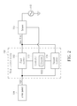
- FIG. 2 is a diagram illustrating a solar inverter system 200 according to another embodiment.
- the controller 106 includes a counter 1062, where the counter 1062 is used for counting number of total output power of the solar inverter system 200 greater than the threshold value (120W) within a predetermined time.
- the controller 106 controls the first inverter 102 and the second inverter 104 to output the total output power of the solar inverter system 200 in turn; when the number of total output power of the solar inverter system 200 greater than the threshold value (120W) within the predetermined time is greater than N, the controller 106 controls the first inverter 102 and the second inverter 104 to output the total output power of the solar inverter system 200 simultaneously, and the first inverter 102 and the second inverter 104 output the maximum output power (120W) of the first inverter 102 in turn.
- the output power of the first inverter 102 is the maximum output power (120W) of the first inverter 102
- the output power of the second inverter 104 is the total output power of the solar inverter system 200 minus the maximum output power (120W) of the first inverter 102
- the output power of the first inverter 102 is the total output power of the solar inverter system 200 minus the maximum output power (120W) of the first inverter 102.
- the solar inverter system 200 further includes the sensor 110. Further, subsequent operational principles of the solar inverter system 200 are the same as those of the solar inverter system 100, so further description thereof is omitted for simplicity.
- FIG. 3 is a flowchart illustrating a control method of a solar inverter system according to another embodiment.
- the control method in FIG. 3 is illustrated using the solar inverter system 100 in FIG. 1 .
- Detailed steps are as follows:
- the threshold value is the maximum output power of the first inverter 102.
- the controller 106 controls the first inverter 102 and the second inverter 104 to output the total output power of the solar inverter system 100 in turn.
- the maximum output power of the first inverter 102 is 120W.
- the controller 106 controls the first inverter 102 and the second inverter 104 to output the total output power (110W) of the solar inverter system 100 in turn.
- Step 310 when the total output power of the solar inverter system 100 is greater than threshold value (120W), the controller 106 controls the first inverter 102 and the second inverter 104 to output the total output power of the solar inverter system 100 simultaneously, and the first inverter 102 and the second inverter 104 output the maximum output power of the first inverter 102 in turn.
- threshold value 120W
- the output power of the second inverter 104 is the total output power of the solar inverter system 100 minus the maximum output power of the first inverter 102; when the output power of the second inverter 104 is the maximum output power of the first inverter 102, the output power of the first inverter 102 is the total output power of the solar inverter system 100 minus the maximum output power of the first inverter 102.
- the controller 106 controls the first inverter 102 and the second inverter 104 to output the total output power (130W) of the solar inverter system 100 simultaneously. Therefore, when the output power of the first inverter 102 is the maximum output power (120W) of the first inverter 102, the output power of the second inverter 104 is the total output power (130W) of the solar inverter system 100 minus the maximum output power (120W) of the first inverter 102. Therefore, the output power of the second inverter 104 is 10W.
- the output power of the second inverter 104 is the maximum output power (120W) of the first inverter 102
- the output power of the first inverter 102 is the total output power (130W) of the solar inverter system 100 minus the maximum output power (120W) of the first inverter 102. Therefore, the output power of the first inverter 102 is 10W.
- Step 306 the controller 106 of the solar inverter system 200 determines whether number of the total output power of the solar inverter system 200 greater than the threshold value (120W) counted by the counter 1062 within the predetermined time is greater than N.
- the controller 106 controls the first inverter 102 and the second inverter 104 to output the total output power of the solar inverter system 200 in turn; when the number of the total output power of the solar inverter system 200 greater than the threshold value (120W) counted by the counter 1062 within the predetermined time is greater than N, the controller 106 controls the first inverter 102 and the second inverter 104 to output the total output power of the solar inverter system 200 simultaneously, and the first inverter 102 and the second inverter 104 output the maximum output power of the first inverter 102 in turn (120W).
- the output power of the first inverter 102 is the maximum output power of the first inverter 102 (120W)
- the output power of the second inverter 104 is the total output power of the solar inverter system 200 minus the maximum output power of the first inverter 102 (120W);
- the output power of the second inverter 104 is the maximum output power of the first inverter 102 (120W)
- the output power of the first inverter 102 is the total output power of the solar inverter system 200 minus the maximum output power of the first inverter 102 (120W).
- the solar inverter system and the control method thereof utilize the controller to calculate the total output power of the solar inverter system and to determine whether the total output power of the solar inverter system is less than the threshold value. Then, when the total output power of the solar inverter system is less than the threshold value, the controller controls the first inverter and the second inverter to output the total output power of the solar inverter system in turn; and when the total output power of the solar inverter system is greater than the threshold value, the controller controls the first inverter and the second inverter to output the total output power of the solar inverter system simultaneously, and the first inverter and the second inverter output the maximum output power of the first inverter in turn.
- the solar inverter system provided by the present invention has better efficiency and lower harmonic distortion.
- the solar inverter system provided by the present invention has longer service life.
Landscapes
- Engineering & Computer Science (AREA)
- Power Engineering (AREA)
- Supply And Distribution Of Alternating Current (AREA)
- Inverter Devices (AREA)
Abstract
A solar inverter system (100, 200) includes a first inverter (102), a second inverter (104), and a controller (106). The first inverter (102) has a first input terminal, and a first output terminal. The first input terminal is coupled to a solar panel (108). The second inverter (104) has a second input terminal, and a second output terminal. The second input terminal is coupled to the solar panel (108). The first output terminal and the second output terminal are parallel with a utility grid (112). The controller (106) is coupled to the first inverter (102) and the second inverter (104) for controlling the first inverter (102) and the second inverter (104) to output total output power in turn, or controlling the first inverter (102) and the second inverter (104) to output the total output power simultaneously.
Description
- The present invention relates to a solar inverter system and a control method thereof according to the pre-characterizing clauses of claims 1 and 8.
- Generally speaking, when output power of an inverter is lower (e.g. output power of an inverter is lower than 30% maximum output power of the inverter), the efficiency and harmonic distortion of a solar inverter system including the inverter are worse. In a solar inverter system with multi-inverters, because total output power of the solar inverter system is evenly distributed to each inverter (therefore, output power of each inverter is the same), output power of each inverter is much lower, resulting in the efficiency and harmonic distortion of the solar inverter system with multi-inverters being much worse. Those skilled in the art can refer to United States Patent No.
7,893,346 and United States Patent No.8,013,472 . - Therefore, in the solar inverter system with multi-inverters, the efficiency and the harmonic distortion of the solar inverter system with multi-inverters are usually worse than a solar inverter system with an inverter because each inverter of the solar inverter system with multi-inverters outputs the same power.
- This in mind, the present invention aims at providing a solar inverter system and a control method thereof that can utilize a controller to control output power of inverters included in the solar inverter system to increase efficiency of the solar inverter system, decrease harmonic distortion of the solar inverter system, and extend service life of the inverters included in the solar inverter system.
- This is achieved by a solar inverter system and a control method thereof according to claims 1 and 8. The dependent claims pertain to corresponding further developments and improvements.
- As will be seen more clearly from the detailed description following below, the claimed solar inverter system includes a first inverter, a second inverter, and a controller. The first inverter has a first input terminal, and a first output terminal. The first input terminal is coupled to a solar panel. The second inverter has a second input terminal, and a second output terminal. The second input terminal is coupled to the solar panel. The first output terminal and the second output terminal are parallel with a utility grid. The controller is coupled to the first inverter and the second inverter for controlling the first inverter and the second inverter to output total output power in turn, or controlling the first inverter and the second inverter to output the total output power simultaneously.
- In the following, the invention is further illustrated by way of example, taking reference to the accompanying drawings thereof:
-
FIG. 1 is a diagram illustrating a solar inverter system according to an embodiment, -
FIG. 2 is a diagram illustrating a solar inverter system according to another embodiment, and -
FIG. 3 is a flowchart illustrating a control method of a solar inverter system according to another embodiment. - Please refer to
FIG. 1. FIG. 1 is a diagram illustrating asolar inverter system 100 according to an embodiment. Thesolar inverter system 100 includes afirst inverter 102, asecond inverter 104, and acontroller 106, where thefirst inverter 102 is the same as thesecond inverter 104. In another embodiment of the present invention, thefirst inverter 102 can also be different from thesecond inverter 104. But, the present invention is not limited to thesolar inverter system 100 only including thefirst inverter 102 and thesecond inverter 104. Therefore, thesolar inverter system 100 can include at least two inverters. Thefirst inverter 102 has a first input terminal and a first output terminal, where the first input terminal is coupled to asolar panel 108; thesecond inverter 104 has a second input terminal and a second output terminal, where the second input terminal is coupled to thesolar panel 108. As shown inFIG. 1 , the first output terminal of thefirst inverter 102 and the second output terminal of thesecond inverter 104 are in parallel with autility grid 112 through asensor 110, where thesensor 110 is used for sensing an alternating current (AC) current IAC and an AC voltage VAC generated by thefirst inverter 102 and thesecond inverter 104 converting a direct current voltage VDC of thesolar panel 108. In addition, theutility grid 112 has an AC frequency (e.g. 50Hz or 60Hz) and an AC voltage (e.g. 110V or 220V). Thecontroller 106 is coupled to thefirst inverter 102, thesecond inverter 104, and thesensor 110 for calculating total output power of thesolar inverter system 100 according to the AC current IAC and the AC voltage VAC, and optionally controlling thefirst inverter 102 and thesecond inverter 104 to output the total output power of thesolar inverter system 100 in turn, or controlling thefirst inverter 102 and thesecond inverter 104 to output the total output power of thesolar inverter system 100 simultaneously. - When the total output power of the
solar inverter system 100 is less than a threshold value (maximum output power of the first inverter 102), thecontroller 106 controls thefirst inverter 102 and thesecond inverter 104 to output the total output power of thesolar inverter system 100 in turn; when the total output power of thesolar inverter system 100 is greater than the threshold value, thecontroller 106 controls thefirst inverter 102 and thesecond inverter 104 to output the total output power of thesolar inverter system 100 simultaneously, and thefirst inverter 102 and thesecond inverter 104 output the maximum output power of thefirst inverter 102 in turn. Therefore, when the total output power of thesolar inverter system 100 is greater than the threshold value and output power of thefirst inverter 102 is the maximum output power of thefirst inverter 102, output power of thesecond inverter 104 is the total output power of thesolar inverter system 100 minus the maximum output power of thefirst inverter 102; and when the total output power of thesolar inverter system 100 is greater than the threshold value and the output power of thesecond inverter 104 is the maximum output power of thefirst inverter 102, the output power of thefirst inverter 102 is the total output power of thesolar inverter system 100 minus the maximum output power of thefirst inverter 102. - For example, the maximum output power of the
first inverter 102 is 120W. When the total output power of thesolar inverter system 100 is 110W, thecontroller 106 controls thefirst inverter 102 and thesecond inverter 104 to output the total output power (110W) of thesolar inverter system 100 in turn because the total output power (110W) of thesolar inverter system 100 is less than the threshold value (120W). When the total output power of thesolar inverter system 100 is 130W, because the total output power (130W) of thesolar inverter system 100 is greater than the threshold value (120W), thecontroller 106 controls thefirst inverter 102 and thesecond inverter 104 to output the total output power (130W) of thesolar inverter system 100 simultaneously, and thefirst inverter 102 and thesecond inverter 104 output the maximum output power (120W) of thefirst inverter 102 in turn. Meanwhile, when the total output power (130W) of thesolar inverter system 100 is greater than the threshold value (120W) and the output power of thefirst inverter 102 is the maximum output power (120W) of thefirst inverter 102, the output power of thesecond inverter 104 is the total output power (130W) of thesolar inverter system 100 minus the maximum output power (120W) of thefirst inverter 102. Therefore, the output power of thesecond inverter 104 is 10W. When the total output power (130W) of thesolar inverter system 100 is greater than the threshold value (120W) and the output power of thesecond inverter 104 is the maximum output power (120W) of thefirst inverter 102, the output power of thefirst inverter 102 is the total output power (130W) of thesolar inverter system 100 minus the maximum output power (120W) of thefirst inverter 102. Therefore, the output power of thefirst inverter 102 is 10W. - In addition, in another embodiment of the present invention, the
solar inverter system 100 further includes thesensor 110. - Please refer to
FIG. 2. FIG. 2 is a diagram illustrating asolar inverter system 200 according to another embodiment. A difference between thesolar inverter system 200 and thesolar inverter system 100 is that thecontroller 106 includes acounter 1062, where thecounter 1062 is used for counting number of total output power of thesolar inverter system 200 greater than the threshold value (120W) within a predetermined time. When the number of the total output power of thesolar inverter system 200 greater than the threshold value (120W) within the predetermined time is less than N (N is a positive integer), thecontroller 106 controls thefirst inverter 102 and thesecond inverter 104 to output the total output power of thesolar inverter system 200 in turn; when the number of total output power of thesolar inverter system 200 greater than the threshold value (120W) within the predetermined time is greater than N, thecontroller 106 controls thefirst inverter 102 and thesecond inverter 104 to output the total output power of thesolar inverter system 200 simultaneously, and thefirst inverter 102 and thesecond inverter 104 output the maximum output power (120W) of thefirst inverter 102 in turn. Therefore, when the output power of thefirst inverter 102 is the maximum output power (120W) of thefirst inverter 102, the output power of thesecond inverter 104 is the total output power of thesolar inverter system 200 minus the maximum output power (120W) of thefirst inverter 102; and when the output power of thesecond inverter 104 is the maximum output power (120W) of thefirst inverter 102, the output power of thefirst inverter 102 is the total output power of thesolar inverter system 200 minus the maximum output power (120W) of thefirst inverter 102. In addition, in another embodiment of the present invention, thesolar inverter system 200 further includes thesensor 110. Further, subsequent operational principles of thesolar inverter system 200 are the same as those of thesolar inverter system 100, so further description thereof is omitted for simplicity. - Please refer to
FIG. 1 ,FIG. 2 , andFIG. 3. FIG. 3 is a flowchart illustrating a control method of a solar inverter system according to another embodiment. The control method inFIG. 3 is illustrated using thesolar inverter system 100 inFIG. 1 . Detailed steps are as follows: - Step 300:
- Start.
- Step 302:
- The
sensor 110 senses an AC current IAC and an AC voltage VAC of the first output terminal of thefirst inverter 102 and the second output terminal of thesecond inverter 104. - Step 304:
- The
controller 106 calculates total output power of thesolar inverter system 100 according to the AC current IAC and the AC voltage VAC. - Step 306:
- The
controller 106 determines whether the total output power of thesolar inverter system 100 is less than a threshold value; if yes, go toStep 308; if no, go toStep 310. - Step 308:
- The
controller 106 controls thefirst inverter 102 and thesecond inverter 104 to output the total output power of thesolar inverter system 100 in turn; go toStep 306. - Step 310:
- The
controller 106 controls thefirst inverter 102 and thesecond inverter 104 to output the total output power of thesolar inverter system 100 simultaneously; go toStep 306. - In
Step 306, the threshold value is the maximum output power of thefirst inverter 102. InStep 308, when the total output power of thesolar inverter system 100 is less than the threshold value, thecontroller 106 controls thefirst inverter 102 and thesecond inverter 104 to output the total output power of thesolar inverter system 100 in turn. For example, the maximum output power of thefirst inverter 102 is 120W. When the total output power of thesolar inverter system 100 is 110W, because the total output power (110W) of thesolar inverter system 100 is less than the threshold value (120W), thecontroller 106 controls thefirst inverter 102 and thesecond inverter 104 to output the total output power (110W) of thesolar inverter system 100 in turn. InStep 310, when the total output power of thesolar inverter system 100 is greater than threshold value (120W), thecontroller 106 controls thefirst inverter 102 and thesecond inverter 104 to output the total output power of thesolar inverter system 100 simultaneously, and thefirst inverter 102 and thesecond inverter 104 output the maximum output power of thefirst inverter 102 in turn. When the output power of thefirst inverter 102 is the maximum output power of thefirst inverter 102, the output power of thesecond inverter 104 is the total output power of thesolar inverter system 100 minus the maximum output power of thefirst inverter 102; when the output power of thesecond inverter 104 is the maximum output power of thefirst inverter 102, the output power of thefirst inverter 102 is the total output power of thesolar inverter system 100 minus the maximum output power of thefirst inverter 102. For example, when the total output power of thesolar inverter system 100 is 130W, because the total output power (130W) of thesolar inverter system 100 is greater than the threshold value (120W), thecontroller 106 controls thefirst inverter 102 and thesecond inverter 104 to output the total output power (130W) of thesolar inverter system 100 simultaneously. Therefore, when the output power of thefirst inverter 102 is the maximum output power (120W) of thefirst inverter 102, the output power of thesecond inverter 104 is the total output power (130W) of thesolar inverter system 100 minus the maximum output power (120W) of thefirst inverter 102. Therefore, the output power of thesecond inverter 104 is 10W. When the output power of thesecond inverter 104 is the maximum output power (120W) of thefirst inverter 102, the output power of thefirst inverter 102 is the total output power (130W) of thesolar inverter system 100 minus the maximum output power (120W) of thefirst inverter 102. Therefore, the output power of thefirst inverter 102 is 10W. - Further, in another embodiment of the present invention (as shown in
FIG. 2 ), inStep 306, thecontroller 106 of thesolar inverter system 200 determines whether number of the total output power of thesolar inverter system 200 greater than the threshold value (120W) counted by thecounter 1062 within the predetermined time is greater than N. When the number of the total output power of thesolar inverter system 200 greater than the threshold value (120W) counted by thecounter 1062 within the predetermined time is less than N, thecontroller 106 controls thefirst inverter 102 and thesecond inverter 104 to output the total output power of thesolar inverter system 200 in turn; when the number of the total output power of thesolar inverter system 200 greater than the threshold value (120W) counted by thecounter 1062 within the predetermined time is greater than N, thecontroller 106 controls thefirst inverter 102 and thesecond inverter 104 to output the total output power of thesolar inverter system 200 simultaneously, and thefirst inverter 102 and thesecond inverter 104 output the maximum output power of thefirst inverter 102 in turn (120W). Meanwhile, when the output power of thefirst inverter 102 is the maximum output power of the first inverter 102 (120W), the output power of thesecond inverter 104 is the total output power of thesolar inverter system 200 minus the maximum output power of the first inverter 102 (120W); when the output power of thesecond inverter 104 is the maximum output power of the first inverter 102 (120W), the output power of thefirst inverter 102 is the total output power of thesolar inverter system 200 minus the maximum output power of the first inverter 102 (120W). - To sum up, the solar inverter system and the control method thereof utilize the controller to calculate the total output power of the solar inverter system and to determine whether the total output power of the solar inverter system is less than the threshold value. Then, when the total output power of the solar inverter system is less than the threshold value, the controller controls the first inverter and the second inverter to output the total output power of the solar inverter system in turn; and when the total output power of the solar inverter system is greater than the threshold value, the controller controls the first inverter and the second inverter to output the total output power of the solar inverter system simultaneously, and the first inverter and the second inverter output the maximum output power of the first inverter in turn. Therefore, because efficiency and harmonic distortion of the solar inverter system are determined by an inverter outputting greater power, compared to the prior art, the solar inverter system provided by the present invention has better efficiency and lower harmonic distortion. In addition, because the first inverter and the second inverter output the maximum output power of the first inverter in turn when the total output power of the solar inverter system is greater than the threshold value, the solar inverter system provided by the present invention has longer service life.
Claims (14)
- A control method of a solar inverter system (100, 200), the solar inverter system (100, 200) comprising a first inverter (102), a second inverter (104), and a controller (106), wherein the first inverter (102) and the second inverter (104) are parallel with a utility grid (112), and the controller (106) is used for optionally controlling the first inverter (102) and the second inverter (104) to output total output power in turn, or controlling the first inverter (102) and the second inverter (104) to output the total output power simultaneously, the control method characterized by:calculating the total output power of the first inverter (102) and the second inverter (104);determining whether the total output power is less than a threshold value; andexecuting a corresponding operation according to a determination result.
- The control method of claim 1, further characterized in that executing the corresponding operation according to the determination result is the controller (106) controlling the first inverter (102) and the second inverter (104) to output the total output power in turn when the total output power is less than the threshold value.
- The control method of claim 1, further characterized in that executing the corresponding operation according to the determination result is the controller (106) controlling the first inverter (102) and the second inverter (104) to output the total output power simultaneously when the total output power is greater than the threshold value, wherein the first inverter (102) and the second inverter (104) output maximum output power of the first inverter (102) in turn.
- The control method of claim 3, further characterized in that the controller (106) controlling the first inverter (102) and the second inverter (104) to output the total output power simultaneously, and the first inverter (102) and the second inverter (104) outputting the maximum output power of the first inverter (102) in turn is output power of the second inverter (104) being the total output power minus the maximum output power of the first inverter (102) when the first inverter (102) outputs the maximum output power of the first inverter (102).
- The control method of claim 3, further characterized in that the controller (106) controlling the first inverter (102) and the second inverter (104) to output the total output power simultaneously, and the first inverter (102) and the second inverter (104) outputting the maximum output power of the first inverter (102) in turn is output power of the first inverter (102) being the total output power minus the maximum output power of the first inverter (102) when the second inverter (104) outputs the maximum output power of the first inverter (102).
- The control method of claim 1, further characterized in that the first output terminal of the first inverter (102) and the second output terminal of the second inverter (104) are coupled to a sensor (110), wherein calculating the total output power of the first inverter (102) and the second inverter (104) comprises:the sensor (110) sensing an alternating current (AC) current and an AC voltage of the first output terminal and the second output terminal; andthe controller (106) calculating the total output power according to the AC current and the AC voltage.
- The control method of claim 1, further characterized in that the controller (106) comprises a counter (1062), wherein the controller (106) controlling the first inverter (102) and the second inverter (104) to output the total output power simultaneously when number of the total output power greater than the threshold value counted by the counter (1062) within a predetermined time is greater than N, and the first inverter (102) and the second inverter (104) output maximum output power of the first inverter (102) in turn, wherein output power of the second inverter (104) is the total output power minus the maximum output power of the first inverter (102) when the first inverter (102) outputs the maximum output power of the first inverter (102); and output power of the first inverter (102) is the total output power minus the maximum output power of the first inverter (102) when the second inverter (104) outputs the maximum output power of the first inverter (102), wherein N is a positive integer.
- A solar inverter system (100, 200), comprising:a first inverter (102) having a first input terminal and a first output terminal, wherein the first input terminal is coupled to a solar panel (108);a second inverter (104) having a second input terminal and a second output terminal, wherein the second input terminal is coupled to the solar panel (108), and the first output terminal and the second output terminal are in parallel with a utility grid (112); anda controller (106) coupled to the first inverter (102) and the second inverter (104), wherein the controller (106) is configured for optionally controlling the first inverter (102) and the second inverter (104) to output total output power in turn, or controlling the first inverter (102) and the second inverter (104) to output the total output power simultaneously.
- The solar inverter system (100, 200) of claim 8, further characterized in that the controller (106) controls the first inverter (102) and the second inverter (104) to output the total output power in turn when the total output power is less than a threshold value.
- The solar inverter system (100, 200) of claim 8, further characterized in that the controller (106) controls the first inverter (102) and the second inverter (104) to output the total output power simultaneously when the total output power is greater than a threshold value, wherein the first inverter (102) and the second inverter (104) output maximum output power of the first inverter (102) in turn.
- The solar inverter system (100, 200) of claim 10, further characterized in that the controller (106) controlling the first inverter (102) and the second inverter (104) to output the total output power simultaneously, and the first inverter (102) and the second inverter (104) outputting the maximum output power of the first inverter (102) in turn is output power of the second inverter (104) being the total output power minus the maximum output power of the first inverter (102) when the first inverter (102) outputs the maximum output power of the first inverter (102).
- The solar inverter system (100, 200) of claim 10, further characterized in that the controller (106) controlling the first inverter (102) and the second inverter (104) to output the total output power simultaneously, and the first inverter (102) and the second inverter (104) outputting the maximum output power of the first inverter (102) in turn is output power of the first inverter (102) being the total output power minus the maximum output power of the first inverter (102) when the second inverter (104) outputting the maximum output power of the first inverter (102).
- The solar inverter system (100, 200) of claim 8, further characterized in that the first output terminal of the first inverter (102) and the second output terminal of the second inverter (104) are coupled to a sensor (110); and the sensor (110) is used for sensing an AC current and an AC voltage of the first output terminal and the second output terminal, and the controller (106) calculates the total output power according to the AC current and the AC voltage.
- The solar inverter system (100, 200) of claim 8, further characterized in that the controller (106) comprises a counter (1062), wherein the controller (106) controls the first inverter (102) and the second inverter (104) to output the total output power simultaneously when number of the total output power greater than a threshold value is greater than N counted by the counter (1062) within a predetermined time, and the first inverter (102) and the second inverter (104) output maximum output power of the first inverter (102) in turn, wherein output power of the second inverter (104) is the total output power minus the maximum output power of the first inverter (102) when the first inverter (102) outputting the maximum output power of the first inverter (102); and output power of the first inverter (102) is the total output power minus the maximum output power of the first inverter (102) when the second inverter (104) outputting the maximum output power of the first inverter (102), wherein N is a positive integer.
Applications Claiming Priority (1)
| Application Number | Priority Date | Filing Date | Title |
|---|---|---|---|
| TW101104011A TWI452796B (en) | 2012-02-08 | 2012-02-08 | Solar inverter system and control method thereof |
Publications (1)
| Publication Number | Publication Date |
|---|---|
| EP2626968A2 true EP2626968A2 (en) | 2013-08-14 |
Family
ID=47678610
Family Applications (1)
| Application Number | Title | Priority Date | Filing Date |
|---|---|---|---|
| EP13153576.7A Withdrawn EP2626968A2 (en) | 2012-02-08 | 2013-02-01 | Solar inverter system and control method thereof |
Country Status (3)
| Country | Link |
|---|---|
| US (1) | US20130201736A1 (en) |
| EP (1) | EP2626968A2 (en) |
| TW (1) | TWI452796B (en) |
Cited By (1)
| Publication number | Priority date | Publication date | Assignee | Title |
|---|---|---|---|---|
| CN104682414A (en) * | 2013-11-29 | 2015-06-03 | 比亚迪股份有限公司 | Method for converters to switch from grid-connecting to grid-disconnecting |
Families Citing this family (6)
| Publication number | Priority date | Publication date | Assignee | Title |
|---|---|---|---|---|
| TWI481146B (en) * | 2011-12-02 | 2015-04-11 | 達方電子股份有限公司 | Solar batteryless off-grid inverter system and control method thereof |
| GB201403560D0 (en) | 2014-02-28 | 2014-04-16 | Eltek As | Inverter system |
| JP2015228778A (en) * | 2014-06-03 | 2015-12-17 | 株式会社日立製作所 | Power converter |
| KR102572424B1 (en) * | 2016-04-08 | 2023-08-29 | 엘에스일렉트릭(주) | Method for controlling of inverter system |
| EP3846337B1 (en) * | 2019-12-30 | 2025-09-10 | Solaredge Technologies Ltd. | Energy harvesting and electrical power generation |
| CN121461618B (en) * | 2026-01-08 | 2026-03-27 | 国网山西省电力有限公司信息通信分公司 | Automatic control method and system for photovoltaic power generation power |
Citations (2)
| Publication number | Priority date | Publication date | Assignee | Title |
|---|---|---|---|---|
| US7893346B2 (en) | 2006-09-28 | 2011-02-22 | Jack Nachamkin | Integrated voltaic energy system |
| US8013472B2 (en) | 2006-12-06 | 2011-09-06 | Solaredge, Ltd. | Method for distributed power harvesting using DC power sources |
Family Cites Families (5)
| Publication number | Priority date | Publication date | Assignee | Title |
|---|---|---|---|---|
| US5408404A (en) * | 1993-03-25 | 1995-04-18 | Rockwell International Corp. | High frequency interleaved DC-to-AC power converter apparatus |
| FI119086B (en) * | 2006-11-06 | 2008-07-15 | Abb Oy | Procedure and arrangement at a wind turbine |
| US20080294916A1 (en) * | 2007-05-04 | 2008-11-27 | Intersil Americas Inc. | Dynamic voltage converter topology switching circuit, system, and method for improving light load efficiency |
| US8345454B1 (en) * | 2009-11-21 | 2013-01-01 | The Boeing Company | Architecture and control method for dynamically conditioning multiple DC sources to driven an AC load |
| TWI449296B (en) * | 2010-05-25 | 2014-08-11 | Univ Nat Sun Yat Sen | Power flow control device |
-
2012
- 2012-02-08 TW TW101104011A patent/TWI452796B/en not_active IP Right Cessation
-
2013
- 2013-01-29 US US13/752,395 patent/US20130201736A1/en not_active Abandoned
- 2013-02-01 EP EP13153576.7A patent/EP2626968A2/en not_active Withdrawn
Patent Citations (2)
| Publication number | Priority date | Publication date | Assignee | Title |
|---|---|---|---|---|
| US7893346B2 (en) | 2006-09-28 | 2011-02-22 | Jack Nachamkin | Integrated voltaic energy system |
| US8013472B2 (en) | 2006-12-06 | 2011-09-06 | Solaredge, Ltd. | Method for distributed power harvesting using DC power sources |
Cited By (2)
| Publication number | Priority date | Publication date | Assignee | Title |
|---|---|---|---|---|
| CN104682414A (en) * | 2013-11-29 | 2015-06-03 | 比亚迪股份有限公司 | Method for converters to switch from grid-connecting to grid-disconnecting |
| CN104682414B (en) * | 2013-11-29 | 2017-08-22 | 比亚迪股份有限公司 | A kind of many transverters realize off-grid method from grid-connected |
Also Published As
| Publication number | Publication date |
|---|---|
| TWI452796B (en) | 2014-09-11 |
| US20130201736A1 (en) | 2013-08-08 |
| TW201334353A (en) | 2013-08-16 |
Similar Documents
| Publication | Publication Date | Title |
|---|---|---|
| EP2626968A2 (en) | Solar inverter system and control method thereof | |
| US20130154395A1 (en) | Solar inverter system and control method thereof | |
| JP6431276B2 (en) | Battery charging system and battery charging method | |
| CN103141004B (en) | Power inverter | |
| EP2566035A3 (en) | Robust control of a grid connected inverter also during grid distortion and faults | |
| EP2362519A3 (en) | System and Method for a Single Stage Power Conversion System | |
| CN103384958B (en) | Power conversion device | |
| EP3026775A1 (en) | Control device for solar power generation inverter | |
| JPWO2012169013A1 (en) | Operation control device for photovoltaic power generation system | |
| GB201306646D0 (en) | Variable voltage drive controller, system and method | |
| CN104811028B (en) | Circuit of power factor correction | |
| CN105048512A (en) | PMSM (permanent magnet synchronous motor) grid-connected operation control method and system, and quasi-synchronization controller | |
| CN104300588B (en) | The control method and device of photovoltaic inverter system | |
| CN102684226A (en) | Energy-saving device and method capable of feeding back electric energy to power grid from parallel connection | |
| CN107508515B (en) | Security control method and device for permanent magnet synchronous motor | |
| CN203261240U (en) | High-frequency high-voltage soft stabilizing power supply used for electrostatic dust collector | |
| EP3846314A3 (en) | Inverter control strategy for a transient heavy load | |
| EP3139488A3 (en) | Dc voltage detector and power conversion device using same | |
| CN104410267A (en) | Switching power source | |
| JP2016005348A (en) | Motor inverter device | |
| JP2015130752A (en) | Air conditioner | |
| CN204761034U (en) | Join in marriage grid voltage and administer device | |
| KR20150005822A (en) | Apparatus and method of controlling instant power failure of h-bridge multi-level inverter | |
| JP2015136271A (en) | Charger and charging method | |
| JP2005304248A (en) | Motor drive inverter control device and electrical equipment |
Legal Events
| Date | Code | Title | Description |
|---|---|---|---|
| PUAI | Public reference made under article 153(3) epc to a published international application that has entered the european phase |
Free format text: ORIGINAL CODE: 0009012 |
|
| AK | Designated contracting states |
Kind code of ref document: A2 Designated state(s): AL AT BE BG CH CY CZ DE DK EE ES FI FR GB GR HR HU IE IS IT LI LT LU LV MC MK MT NL NO PL PT RO RS SE SI SK SM TR |
|
| AX | Request for extension of the european patent |
Extension state: BA ME |
|
| STAA | Information on the status of an ep patent application or granted ep patent |
Free format text: STATUS: THE APPLICATION IS DEEMED TO BE WITHDRAWN |
|
| 18D | Application deemed to be withdrawn |
Effective date: 20150901 |