EP2626865A1 - Nuclear power plant control system and nuclear power plant control method - Google Patents
Nuclear power plant control system and nuclear power plant control method Download PDFInfo
- Publication number
- EP2626865A1 EP2626865A1 EP11830543.2A EP11830543A EP2626865A1 EP 2626865 A1 EP2626865 A1 EP 2626865A1 EP 11830543 A EP11830543 A EP 11830543A EP 2626865 A1 EP2626865 A1 EP 2626865A1
- Authority
- EP
- European Patent Office
- Prior art keywords
- power plant
- nuclear power
- phenomenon
- signal
- systems
- Prior art date
- Legal status (The legal status is an assumption and is not a legal conclusion. Google has not performed a legal analysis and makes no representation as to the accuracy of the status listed.)
- Ceased
Links
- 238000000034 method Methods 0.000 title claims description 10
- 238000001514 detection method Methods 0.000 claims abstract description 41
- 230000008054 signal transmission Effects 0.000 claims description 2
- 238000010586 diagram Methods 0.000 description 9
- 230000007257 malfunction Effects 0.000 description 2
- 238000004353 relayed correlation spectroscopy Methods 0.000 description 1
- 238000000926 separation method Methods 0.000 description 1
Images


Classifications
-
- G—PHYSICS
- G21—NUCLEAR PHYSICS; NUCLEAR ENGINEERING
- G21D—NUCLEAR POWER PLANT
- G21D3/00—Control of nuclear power plant
- G21D3/04—Safety arrangements
-
- G—PHYSICS
- G21—NUCLEAR PHYSICS; NUCLEAR ENGINEERING
- G21C—NUCLEAR REACTORS
- G21C7/00—Control of nuclear reaction
- G21C7/36—Control circuits
-
- G—PHYSICS
- G21—NUCLEAR PHYSICS; NUCLEAR ENGINEERING
- G21D—NUCLEAR POWER PLANT
- G21D3/00—Control of nuclear power plant
-
- G—PHYSICS
- G21—NUCLEAR PHYSICS; NUCLEAR ENGINEERING
- G21C—NUCLEAR REACTORS
- G21C17/00—Monitoring; Testing ; Maintaining
-
- Y—GENERAL TAGGING OF NEW TECHNOLOGICAL DEVELOPMENTS; GENERAL TAGGING OF CROSS-SECTIONAL TECHNOLOGIES SPANNING OVER SEVERAL SECTIONS OF THE IPC; TECHNICAL SUBJECTS COVERED BY FORMER USPC CROSS-REFERENCE ART COLLECTIONS [XRACs] AND DIGESTS
- Y02—TECHNOLOGIES OR APPLICATIONS FOR MITIGATION OR ADAPTATION AGAINST CLIMATE CHANGE
- Y02E—REDUCTION OF GREENHOUSE GAS [GHG] EMISSIONS, RELATED TO ENERGY GENERATION, TRANSMISSION OR DISTRIBUTION
- Y02E30/00—Energy generation of nuclear origin
-
- Y—GENERAL TAGGING OF NEW TECHNOLOGICAL DEVELOPMENTS; GENERAL TAGGING OF CROSS-SECTIONAL TECHNOLOGIES SPANNING OVER SEVERAL SECTIONS OF THE IPC; TECHNICAL SUBJECTS COVERED BY FORMER USPC CROSS-REFERENCE ART COLLECTIONS [XRACs] AND DIGESTS
- Y02—TECHNOLOGIES OR APPLICATIONS FOR MITIGATION OR ADAPTATION AGAINST CLIMATE CHANGE
- Y02E—REDUCTION OF GREENHOUSE GAS [GHG] EMISSIONS, RELATED TO ENERGY GENERATION, TRANSMISSION OR DISTRIBUTION
- Y02E30/00—Energy generation of nuclear origin
- Y02E30/30—Nuclear fission reactors
Definitions
- the present invention relates to a nuclear power plant control system and a nuclear power plant control method, and particularly relates to a nuclear power plant control system and a nuclear power plant control method capable of achieving high reliability while connecting systems having different multiplicities.
- a nuclear power plant control system that controls a nuclear power plant includes a plurality of independently operating systems to achieve high reliability (for example, see Patent Literature 1).
- An example of a configuration of the nuclear power plant control system including a plurality of systems will be described with reference to FIGS. 5 and 6 .
- FIG. 5 is a diagram illustrating an example of a configuration of a conventional nuclear power plant control system.
- a nuclear power plant control system 1 illustrated in FIG. 5 is a control system that controls a nuclear reactor trip, and includes a duplex channel and a duplex train.
- a channel is a system that detects a phenomenon occurring in a nuclear power plant
- a train is a system that performs a logical operation based on a detection result of the channel.
- a detection unit 10a included in a channel I includes a sensor that detects a specific phenomenon (for example, a rise in pressure in a particular part and the like) occurring in the nuclear power plant, and a threshold operation unit that performs a threshold operation of a detected value of the sensor. When a detected value of the sensor exceeds a threshold, the detection unit 10a outputs a signal that indicates an occurrence of a specific phenomenon to an input unit 21a included in a train A.
- a specific phenomenon for example, a rise in pressure in a particular part and the like
- a detection unit 10b included in a channel II includes a sensor and a threshold operation unit similar to those of the detection unit 10a, and outputs a signal that indicates an occurrence of a specific phenomenon to an input unit 21b included in a train B when a detected value of the sensor exceeds a threshold.
- a trip control device 20 including the input unit 21a and the input unit 21b trips a nuclear reactor when a signal is input to at least one of the input unit 21a and the input unit 21b.
- the nuclear power plant control system 1 may maintain a function even when a malfunction occurs in a portion of the channel or the train.
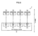
- FIG. 6 is a diagram illustrating an example of a configuration of a recent nuclear power plant control system.
- a nuclear power plant control system 2 illustrated in FIG. 6 is a control system that controls a nuclear reactor trip, and includes a quadruple channel of a channel I to a channel IV.
- a channel I includes a detection unit 30a and an input unit 41a.
- a channel II includes a detection unit 30b and an input unit 41b.
- a channel III includes a detection unit 30c and an input unit 41c.
- a channel IV includes a detection unit 30d and an input unit 41d.
- the respective detection units 30a to 30d include a sensor that detects a specific phenomenon occurring in a nuclear power plant, and a threshold operation unit that performs a threshold operation of a detected value of the sensor. When a detected value of the sensor exceeds a threshold, the detection units 30a to 30d output a signal that indicates an occurrence of a specific phenomenon to an input unit 41 included in the same channel.
- a trip control device 40 including input units 41a to 41d trips a nuclear reactor when a signal is input to at least two of the input units 41a to 41d.
- the nuclear power plant control system 2 may maintain a function even when a malfunction occurs in a portion of the channel.
- a nuclear power plant control system includes a plurality of systems, and a multiplicity varies according to a system.
- a recent system has a high multiplicity. For this reason, when a portion of an existing nuclear power plant control system is to be replaced by a recent equipment to improve a function and the like, a simple replacement of the equipment may not respond since a multiplicity is different.
- the detection units 10a and 10b illustrated in FIG. 5 are to be replaced by the detection units 30a to 30d illustrated in FIG. 6 , these may not be simply connected since the input units 21a and 21b are a duplex unit while the detection units 30a to 30d are a quadruple unit.
- the detection units 10a and 10b illustrated in FIG. 5 are to be replaced by the detection units 30a to 30d illustrated in FIG. 6 , these may not be simply connected since the input units 21a and 21b are a duplex unit while the detection units 30a to 30d are a quadruple unit.
- redundancy is lost, and reliability which is significant for a nuclear power plant control system may be degraded.
- the invention is conceived in view of the above, and an object of the invention is to provide a nuclear power plant control system and a nuclear power plant control method capable of achieving high reliability while connecting systems having different multiplicities to each other.
- a nuclear power plant control system includes: detection units that detect a phenomenon occurring in a nuclear power plant for each of M systems; a start unit that starts processing corresponding to the phenomenon in a case where a signal that indicates an occurrence of the phenomenon is input from a predetermined number or more of signal lines out of L signal lines; and a majority circuit, provided for each of the L signal lines, each of which outputting a signal that indicates an occurrence of the phenomenon to a corresponding signal line in a case where the phenomenon is detected in N or more systems out of the M systems of the detection units.
- L is an integer greater than or equal to 1
- M is an integer greater than or equal to 2
- N is an integer greater than or equal to 1.
- the nuclear power plant control system includes majority circuits corresponding to systems of a connection destination on a one-to-one basis, and each majority circuit outputs a signal to the connection destination in response to a detection status at a connection source. Accordingly, it is possible to achieve high reliability while connecting systems having different multiplicities to each other.
- the majority circuit is combined with a relay or a breaker provided for each of the M systems.
- the majority circuit is combined with the relay or the breaker which is a device that reliability is verified, reliability of the majority circuit may be ensured.
- the relay or the breaker is multiplexed for each of the M systems.
- reliability of the majority circuit may be enhanced by multiplexing the relay or the breaker.
- a nuclear power plant control method of controlling a transmission of a signal between detection units that detect a phenomenon occurring in a nuclear power plant for each of M systems and a start unit that starts processing corresponding to the phenomenon in a case where a signal that indicates an occurrence of the phenomenon is input from a predetermined number or more of signal lines out of L signal lines includes: receiving, by a majority circuit provided for each of the L signal lines, a signal that indicates whether the phenomenon is detected from each of the M systems, and outputting, by the majority circuit, a signal that indicates an occurrence of the phenomenon to a corresponding signal line in a case where a signal indicating that the phenomenon is detected is received from N or more systems out of the M systems.
- L is an integer greater than or equal to 1
- M is an integer greater than or equal to 2
- N is an integer greater than or equal to 1.
- majority circuits corresponding to systems of a connection destination on a one-to-one basis are provided, and each majority circuit outputs a signal to the connection destination in response to a detection status at a connection source. Accordingly, it is possible to achieve high reliability while connecting systems having different multiplicities to each other.
- the nuclear power plant control system and the nuclear power plant control method according to the invention have an effect of achieving high reliability while connecting systems having different multiplicities to each other.
- FIG. 1 is a diagram illustrating a schematic configuration of a nuclear power plant control system according to the Embodiment.
- a nuclear power plant control system 3 illustrated in FIG. 1 is a control system that controls a nuclear reactor trip, and includes detection units 30a to 30d, a trip control device 20, and majority circuits 50a and 50b.
- the respective detection units 30a to 30d include a sensor that detects a specific phenomenon occurring in a nuclear power plant, and a threshold operation unit that performs a threshold operation of a detected value of the sensor, and output a signal that indicates an occurrence of a specific phenomenon when a detected value of the sensor exceeds a threshold.
- the trip control device 20 illustrated in FIG. 5 the trip control device 20 includes an input unit 21a and an input unit 21b, and trips a nuclear reactor when a signal that indicates an occurrence of a specific phenomenon is input to at least one of the input unit 21a and the input unit 21b.
- the nuclear power plant control system 3 includes a quadruple channel and a duplex train.
- the majority circuits 50a and 50b connect the quadruple channel to the duplex train. Specifically, the majority circuit 50a is connected to the respective detection units 30a to 30d, and outputs a signal that indicates an occurrence of a specific phenomenon to the input unit 21a through a signal line Sa when the signal that indicates an occurrence of a specific phenomenon is input from at least two of the detection units 30a to 30d. In addition, the majority circuit 50b is connected to the respective detection units 30a to 30d, and outputs a signal that indicates an occurrence of a specific phenomenon to the input unit 21b through a signal line Sb when the signal that indicates an occurrence of a specific phenomenon is input from at least two of the detection units 30a to 30d.
- a first channel and a second channel may be connected to a first train via an OR circuit
- a third channel and a fourth channel may be connected to a second train via an OR circuit
- all channels may be connected to the first train via an OR circuit, and all channels may be connected to the second train via an OR circuit.
- OR circuit an OR circuit
- the majority circuits 50a and 50b illustrated in FIG. 1 will be described in detail with reference to FIGS. 2 to 4 .
- the majority circuits 50a and 50b have similar configurations. Thus, hereinafter, the operation and the configuration will be described using the majority circuit 50a as an example.
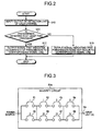
- FIG. 2 is a flowchart illustrating an operation of the majority circuit 50a.
- the majority circuit 50a executes the operation illustrated in FIG. 2 at predetermined intervals.
- step S10 the majority circuit 50a verifies an output of a detection unit 30 of each channel.
- the majority circuit 50a outputs a signal that indicates the occurrence of a specific phenomenon (for example, "1") to the input unit 21a via the signal line Sa in step S12.
- the majority circuit 50a when an occurrence of a specific phenomenon is not detected in the detection units 30 of at least two channels (No in step S11), the majority circuit 50a outputs a signal indicating that the specific phenomenon does not occur (for example, "0") to the input unit 21a via the signal line Sa in step S13.
- FIG. 3 is a diagram illustrating an example of a configuration of the majority circuit 50a.
- the majority circuit 50a includes relays 51 and 52 operating based on a signal received from the channel I, relays 53 and 55 operating based on a signal received from the channel II, relays 54 and 56 operating based on a signal received from the channel III, and relays 57 and 58 operating based on a signal received from the channel IV.
- the majority circuit 50a when the majority circuit 50a is combined with a relay which has been used for a long time, and is a device that reliability is verified, reliability of the majority circuit 50a may be ensured.
- the relay as illustrated in FIG. 4 , the channel and the train may be physically separated from each other in a portion of a contact point. When the channel and the train are desired to be separated from each other to ensure safety, it is important to physically separate the channel and the train from each other.
- the majority circuits 50a and 50b may be combined with a breaker which is a device that reliability is verified similarly to the relay.
- the majority circuits 50a and 50b are provided, it is possible to achieve a nuclear power plant control system having high reliability while connecting the channel and the train having different multiplicities to each other.
- the configuration of the nuclear power plant control system described in the above Embodiment may be arbitrarily changed without departing from the scope of the invention.
- the nuclear power plant control system that performs a control of a nuclear reactor trip is given as an example.
- the invention is effective for a control system that performs another control.
- a multiplicity of each unit of the nuclear power plant control system described in the above Embodiment may be arbitrarily changed according to a desired degree of reliability and the like.
- detection means corresponding to the detection units 30a to 30d
- a start means corresponding to the trip control device 20
- a majority circuit may be provided for each of the L signal lines, and each majority circuit may output a signal that indicates an occurrence of the phenomenon to a corresponding signal line in a case where the phenomenon is detected in N or more systems out of the M systems of the detection means.
- L is an integer greater than or equal to 1
- M is an integer greater than or equal to 2
- N is an integer greater than or equal to 1.
Landscapes
- Physics & Mathematics (AREA)
- Engineering & Computer Science (AREA)
- Plasma & Fusion (AREA)
- General Engineering & Computer Science (AREA)
- High Energy & Nuclear Physics (AREA)
- Business, Economics & Management (AREA)
- Emergency Management (AREA)
- Chemical & Material Sciences (AREA)
- Chemical Kinetics & Catalysis (AREA)
- Safety Devices In Control Systems (AREA)
- Testing And Monitoring For Control Systems (AREA)
Abstract
Description
- The present invention relates to a nuclear power plant control system and a nuclear power plant control method, and particularly relates to a nuclear power plant control system and a nuclear power plant control method capable of achieving high reliability while connecting systems having different multiplicities.
- A nuclear power plant control system that controls a nuclear power plant includes a plurality of independently operating systems to achieve high reliability (for example, see Patent Literature 1). An example of a configuration of the nuclear power plant control system including a plurality of systems will be described with reference to
FIGS. 5 and6 . -
FIG. 5 is a diagram illustrating an example of a configuration of a conventional nuclear power plant control system. A nuclear powerplant control system 1 illustrated inFIG. 5 is a control system that controls a nuclear reactor trip, and includes a duplex channel and a duplex train. Herein, a channel is a system that detects a phenomenon occurring in a nuclear power plant, and a train is a system that performs a logical operation based on a detection result of the channel. - In the nuclear power
plant control system 1, adetection unit 10a included in a channel I includes a sensor that detects a specific phenomenon (for example, a rise in pressure in a particular part and the like) occurring in the nuclear power plant, and a threshold operation unit that performs a threshold operation of a detected value of the sensor. When a detected value of the sensor exceeds a threshold, thedetection unit 10a outputs a signal that indicates an occurrence of a specific phenomenon to aninput unit 21a included in a train A. - A
detection unit 10b included in a channel II includes a sensor and a threshold operation unit similar to those of thedetection unit 10a, and outputs a signal that indicates an occurrence of a specific phenomenon to aninput unit 21b included in a train B when a detected value of the sensor exceeds a threshold. - A
trip control device 20 including theinput unit 21a and theinput unit 21b trips a nuclear reactor when a signal is input to at least one of theinput unit 21a and theinput unit 21b. By such a configuration, the nuclear powerplant control system 1 may maintain a function even when a malfunction occurs in a portion of the channel or the train. -
FIG. 6 is a diagram illustrating an example of a configuration of a recent nuclear power plant control system. A nuclear powerplant control system 2 illustrated inFIG. 6 is a control system that controls a nuclear reactor trip, and includes a quadruple channel of a channel I to a channel IV. A channel I includes adetection unit 30a and aninput unit 41a. A channel II includes adetection unit 30b and aninput unit 41b. A channel III includes adetection unit 30c and aninput unit 41c. A channel IV includes adetection unit 30d and aninput unit 41d. - In the nuclear power
plant control system 2, therespective detection units 30a to 30d include a sensor that detects a specific phenomenon occurring in a nuclear power plant, and a threshold operation unit that performs a threshold operation of a detected value of the sensor. When a detected value of the sensor exceeds a threshold, thedetection units 30a to 30d output a signal that indicates an occurrence of a specific phenomenon to an input unit 41 included in the same channel. - A
trip control device 40 includinginput units 41a to 41d trips a nuclear reactor when a signal is input to at least two of theinput units 41a to 41d. By such a configuration, the nuclear powerplant control system 2 may maintain a function even when a malfunction occurs in a portion of the channel. -
- Patent Literature 1: Japanese Patent Application Laid-open No.
6-27293 - As previously described, a nuclear power plant control system includes a plurality of systems, and a multiplicity varies according to a system. In general, a recent system has a high multiplicity. For this reason, when a portion of an existing nuclear power plant control system is to be replaced by a recent equipment to improve a function and the like, a simple replacement of the equipment may not respond since a multiplicity is different.
- For example, the
detection units FIG. 5 are to be replaced by thedetection units 30a to 30d illustrated inFIG. 6 , these may not be simply connected since theinput units detection units 30a to 30d are a quadruple unit. In addition, when systems having different multiplicities are inappropriately connected to each other, redundancy is lost, and reliability which is significant for a nuclear power plant control system may be degraded. - The invention is conceived in view of the above, and an object of the invention is to provide a nuclear power plant control system and a nuclear power plant control method capable of achieving high reliability while connecting systems having different multiplicities to each other.
- According to an aspect of the present invention, a nuclear power plant control system includes: detection units that detect a phenomenon occurring in a nuclear power plant for each of M systems; a start unit that starts processing corresponding to the phenomenon in a case where a signal that indicates an occurrence of the phenomenon is input from a predetermined number or more of signal lines out of L signal lines; and a majority circuit, provided for each of the L signal lines, each of which outputting a signal that indicates an occurrence of the phenomenon to a corresponding signal line in a case where the phenomenon is detected in N or more systems out of the M systems of the detection units. L is an integer greater than or equal to 1, M is an integer greater than or equal to 2, and N is an integer greater than or equal to 1.
- The nuclear power plant control system includes majority circuits corresponding to systems of a connection destination on a one-to-one basis, and each majority circuit outputs a signal to the connection destination in response to a detection status at a connection source. Accordingly, it is possible to achieve high reliability while connecting systems having different multiplicities to each other.
- Advantageously, in the nuclear power plant control system, the majority circuit is combined with a relay or a breaker provided for each of the M systems.
- In this aspect, since the majority circuit is combined with the relay or the breaker which is a device that reliability is verified, reliability of the majority circuit may be ensured.
- Advantageously, in the nuclear power plant control system, the relay or the breaker is multiplexed for each of the M systems.
- In this aspect, reliability of the majority circuit may be enhanced by multiplexing the relay or the breaker.
- According to another aspect of the present invention, a nuclear power plant control method of controlling a transmission of a signal between detection units that detect a phenomenon occurring in a nuclear power plant for each of M systems and a start unit that starts processing corresponding to the phenomenon in a case where a signal that indicates an occurrence of the phenomenon is input from a predetermined number or more of signal lines out of L signal lines, includes: receiving, by a majority circuit provided for each of the L signal lines, a signal that indicates whether the phenomenon is detected from each of the M systems, and outputting, by the majority circuit, a signal that indicates an occurrence of the phenomenon to a corresponding signal line in a case where a signal indicating that the phenomenon is detected is received from N or more systems out of the M systems. L is an integer greater than or equal to 1, M is an integer greater than or equal to 2, and N is an integer greater than or equal to 1.
- In the nuclear power plant control method, majority circuits corresponding to systems of a connection destination on a one-to-one basis are provided, and each majority circuit outputs a signal to the connection destination in response to a detection status at a connection source. Accordingly, it is possible to achieve high reliability while connecting systems having different multiplicities to each other.
- The nuclear power plant control system and the nuclear power plant control method according to the invention have an effect of achieving high reliability while connecting systems having different multiplicities to each other.
-
-
FIG. 1 is a diagram illustrating a schematic configuration of a nuclear power plant control system according to the Embodiment. -
FIG. 2 is a flowchart illustrating an operation of a majority circuit. -
FIG. 3 is a diagram illustrating an example of a configuration of the majority circuit. -
FIG. 4 is a diagram illustrating an example of a separation of a channel and a train. -
FIG. 5 is a diagram illustrating an example of a configuration of a conventional nuclear power plant control system. -
FIG. 6 is a diagram illustrating an example of a configuration of a recent nuclear power plant control system. - Hereinafter, Embodiment of a nuclear power plant control system and a nuclear power plant control method according to the invention will be described in detail based on drawings. It should be noted that the invention is not limited to the Embodiment. In addition, components in the Embodiment contain the equivalent including a component easily assumed by those skilled in the art, and the substantially same component.
- First, a configuration of a nuclear power plant control system according to the Embodiment will be described with reference to
FIG. 1. FIG. 1 is a diagram illustrating a schematic configuration of a nuclear power plant control system according to the Embodiment. A nuclear powerplant control system 3 illustrated inFIG. 1 is a control system that controls a nuclear reactor trip, and includesdetection units 30a to 30d, atrip control device 20, andmajority circuits - Similarly to the
detection units 30a to 30d illustrated inFIG. 6 , therespective detection units 30a to 30d include a sensor that detects a specific phenomenon occurring in a nuclear power plant, and a threshold operation unit that performs a threshold operation of a detected value of the sensor, and output a signal that indicates an occurrence of a specific phenomenon when a detected value of the sensor exceeds a threshold. Similarly to thetrip control device 20 illustrated inFIG. 5 , thetrip control device 20 includes aninput unit 21a and aninput unit 21b, and trips a nuclear reactor when a signal that indicates an occurrence of a specific phenomenon is input to at least one of theinput unit 21a and theinput unit 21b. - In this way, the nuclear power
plant control system 3 includes a quadruple channel and a duplex train. - The
majority circuits majority circuit 50a is connected to therespective detection units 30a to 30d, and outputs a signal that indicates an occurrence of a specific phenomenon to theinput unit 21a through a signal line Sa when the signal that indicates an occurrence of a specific phenomenon is input from at least two of thedetection units 30a to 30d. In addition, themajority circuit 50b is connected to therespective detection units 30a to 30d, and outputs a signal that indicates an occurrence of a specific phenomenon to theinput unit 21b through a signal line Sb when the signal that indicates an occurrence of a specific phenomenon is input from at least two of thedetection units 30a to 30d. - To connect the quadruple channel to the duplex train, for example, a first channel and a second channel may be connected to a first train via an OR circuit, and a third channel and a fourth channel may be connected to a second train via an OR circuit. However, in this case, when one of the OR circuits breaks down, or a function is suspended to conduct a test, a detection result in a channel connected to the OR circuit is not reflected on a control, and reliability is significantly degraded.
- In addition, to connect the quadruple channel to the duplex train, for example, all channels may be connected to the first train via an OR circuit, and all channels may be connected to the second train via an OR circuit. However, in this case, when one channel merely erroneously outputs a signal, processing of a nuclear reactor trip and the like is erroneously executed even when the other channels normally operate.
- As illustrated in
FIG. 1 , when majority circuits and trains are connected to each other on a one-to-one basis by providing the same number of the majority circuits as that of the trains, and outputs of all channels are input to the respective majority circuits, it is possible to connect channels and trains having different multiplicities to each other while retaining high reliability. - Next, an operation and a configuration of the
majority circuits FIG. 1 will be described in detail with reference toFIGS. 2 to 4 . Themajority circuits majority circuit 50a as an example. -
FIG. 2 is a flowchart illustrating an operation of themajority circuit 50a. Themajority circuit 50a executes the operation illustrated inFIG. 2 at predetermined intervals. As illustrated inFIG. 2 , in step S10, themajority circuit 50a verifies an output of a detection unit 30 of each channel. Then, when an occurrence of a specific phenomenon is detected in the detection units 30 of at least two channels (Yes in step S11), themajority circuit 50a outputs a signal that indicates the occurrence of a specific phenomenon (for example, "1") to theinput unit 21a via the signal line Sa in step S12. - On the other hand, when an occurrence of a specific phenomenon is not detected in the detection units 30 of at least two channels (No in step S11), the
majority circuit 50a outputs a signal indicating that the specific phenomenon does not occur (for example, "0") to theinput unit 21a via the signal line Sa in step S13. -
FIG. 3 is a diagram illustrating an example of a configuration of themajority circuit 50a. In the example illustrated inFIG. 3 , themajority circuit 50a includesrelays - In this way, when the
majority circuit 50a is combined with a relay which has been used for a long time, and is a device that reliability is verified, reliability of themajority circuit 50a may be ensured. In addition, by using the relay, as illustrated inFIG. 4 , the channel and the train may be physically separated from each other in a portion of a contact point. When the channel and the train are desired to be separated from each other to ensure safety, it is important to physically separate the channel and the train from each other. Themajority circuits - As described in the foregoing, in the Embodiment, since the
majority circuits - The configuration of the nuclear power plant control system described in the above Embodiment may be arbitrarily changed without departing from the scope of the invention. For example, in the above Embodiment, the nuclear power plant control system that performs a control of a nuclear reactor trip is given as an example. However, the invention is effective for a control system that performs another control.
- In addition, a multiplicity of each unit of the nuclear power plant control system described in the above Embodiment may be arbitrarily changed according to a desired degree of reliability and the like. Specifically, when detection means (corresponding to the
detection units 30a to 30d) that detect a phenomenon occurring in a nuclear power plant for each of M systems are connected to a start means (corresponding to the trip control device 20) that starts processing corresponding to the phenomenon in a case where a signal that indicates an occurrence of the phenomenon is input from a predetermined number or more of signal lines out of L signal lines, a majority circuit may be provided for each of the L signal lines, and each majority circuit may output a signal that indicates an occurrence of the phenomenon to a corresponding signal line in a case where the phenomenon is detected in N or more systems out of the M systems of the detection means. However, L is an integer greater than or equal to 1, M is an integer greater than or equal to 2, and N is an integer greater than or equal to 1. -
- 1 to 3
- NUCLEAR POWER PLANT CONTROL SYSTEM
- 10a, 10b
- DETECTION UNIT
- 20
- TRIP CONTROL DEVICE
- 21a, 21b
- INPUT UNIT
- 30a to 30d
- DETECTION UNIT
- 40
- TRIP CONTROL DEVICE
- 41a to 41d
- INPUT UNIT
- 50a, 50b
- MAJORITY CIRCUIT
- 51 to 58
- RELAY
Claims (5)
- A nuclear power plant control system, comprising:detection units that detect a phenomenon occurring in a nuclear power plant for each of M systems;a start unit that starts processing corresponding to the phenomenon in a case where a signal that indicates an occurrence of the phenomenon is input from a predetermined number or more of signal lines out of L signal lines; anda majority circuit, provided for each of the L signal lines, each of which outputting a signal that indicates an occurrence of the phenomenon to a corresponding signal line in a case where the phenomenon is detected in N or more systems out of the M systems of the detection units,wherein L is an integer greater than or equal to 1, M is an integer greater than or equal to 2, and N is an integer greater than or equal to 1.
- The nuclear power plant control system according to claim 1, wherein the majority circuit is combined with a relay or a breaker provided for each of the M systems.
- The nuclear power plant control system according to claim 2, wherein the relay or the breaker is multiplexed for each of the M systems.
- The nuclear power plant control system according to any one of claims 1 to 3, wherein the start unit is a trip control device of a nuclear reactor.
- A nuclear power plant control method of controlling a transmission of a signal between detection units that detect a phenomenon occurring in a nuclear power plant for each of M systems and a start unit that starts processing corresponding to the phenomenon in a case where a signal that indicates an occurrence of the phenomenon is input from a predetermined number or more of signal lines out of L signal lines, the method comprising:receiving, by a majority circuit provided for each of the L signal lines, a signal that indicates whether the phenomenon is detected from each of the M systems, andoutputting, by the majority circuit, a signal that indicates an occurrence of the phenomenon to a corresponding signal line in a case where a signal indicating that the phenomenon is detected is received from N or more systems out of the M systems,wherein L is an integer greater than or equal to 1, M is an integer greater than or equal to 2, and N is an integer greater than or equal to 1.
Applications Claiming Priority (2)
| Application Number | Priority Date | Filing Date | Title |
|---|---|---|---|
| JP2010225274A JP5796945B2 (en) | 2010-10-04 | 2010-10-04 | Nuclear power plant control system and control method for nuclear power plant control system |
| PCT/JP2011/072315 WO2012046610A1 (en) | 2010-10-04 | 2011-09-29 | Nuclear power plant control system and nuclear power plant control method |
Publications (2)
| Publication Number | Publication Date |
|---|---|
| EP2626865A1 true EP2626865A1 (en) | 2013-08-14 |
| EP2626865A4 EP2626865A4 (en) | 2017-07-05 |
Family
ID=45927605
Family Applications (1)
| Application Number | Title | Priority Date | Filing Date |
|---|---|---|---|
| EP11830543.2A Ceased EP2626865A4 (en) | 2010-10-04 | 2011-09-29 | Nuclear power plant control system and nuclear power plant control method |
Country Status (4)
| Country | Link |
|---|---|
| US (1) | US9748008B2 (en) |
| EP (1) | EP2626865A4 (en) |
| JP (1) | JP5796945B2 (en) |
| WO (1) | WO2012046610A1 (en) |
Family Cites Families (10)
| Publication number | Priority date | Publication date | Assignee | Title |
|---|---|---|---|---|
| US4697093A (en) * | 1985-01-23 | 1987-09-29 | Westinghouse Electric Corp. | Testable, fault-tolerant power interface circuit for controlling plant process equipment |
| JPH0715514B2 (en) * | 1986-05-29 | 1995-02-22 | 株式会社東芝 | Reactor emergency stop device |
| JPS63234193A (en) * | 1987-03-23 | 1988-09-29 | 株式会社日立製作所 | Reactor safety protection device |
| JPS63252299A (en) * | 1987-04-09 | 1988-10-19 | 株式会社日立製作所 | Reactor safety protection device |
| JPH0731537B2 (en) * | 1987-09-11 | 1995-04-10 | 株式会社日立製作所 | Multiplex controller |
| US4832898A (en) | 1987-11-25 | 1989-05-23 | Westinghouse Electric Corp. | Variable delay reactor protection system |
| JP2912425B2 (en) * | 1990-06-15 | 1999-06-28 | 株式会社日立製作所 | Reactor safety protection device |
| JP2903877B2 (en) | 1992-07-07 | 1999-06-14 | 株式会社日立製作所 | Reactor safety protection device |
| JP2501178B2 (en) * | 1994-01-26 | 1996-05-29 | 株式会社日立製作所 | Reactor safety protection device |
| KR100980043B1 (en) * | 2008-10-22 | 2010-09-06 | 한국전력기술 주식회사 | Power plant protection system and method using FPA |
-
2010
- 2010-10-04 JP JP2010225274A patent/JP5796945B2/en active Active
-
2011
- 2011-09-29 WO PCT/JP2011/072315 patent/WO2012046610A1/en not_active Ceased
- 2011-09-29 US US13/877,269 patent/US9748008B2/en active Active
- 2011-09-29 EP EP11830543.2A patent/EP2626865A4/en not_active Ceased
Non-Patent Citations (1)
| Title |
|---|
| See references of WO2012046610A1 * |
Also Published As
| Publication number | Publication date |
|---|---|
| WO2012046610A1 (en) | 2012-04-12 |
| US9748008B2 (en) | 2017-08-29 |
| JP5796945B2 (en) | 2015-10-21 |
| EP2626865A4 (en) | 2017-07-05 |
| US20130182809A1 (en) | 2013-07-18 |
| JP2012078263A (en) | 2012-04-19 |
Similar Documents
| Publication | Publication Date | Title |
|---|---|---|
| KR101552852B1 (en) | Triple redundant digital protective relay and operating method thereof | |
| EP3653559A3 (en) | Interface unit, elevator system and method | |
| JP3897046B2 (en) | Information processing apparatus and information processing method | |
| EP2779341B1 (en) | Protection control system and merging unit | |
| EP2988389B1 (en) | Redundant high reliability power supply configuration and testing | |
| CN103561823A (en) | Fault-tolerant fire protection system | |
| EP2254246A1 (en) | Control circuit for controlling a semiconductor switch system | |
| EP1857937A1 (en) | Information processing apparatus and information processing method | |
| CN108861911B (en) | Elevator data communication arrangement | |
| EP2806112A1 (en) | Power load imbalance detection device and power load imbalance detection method | |
| KR101817641B1 (en) | Dual power supply for remote terminal unit having conour route | |
| US9053245B2 (en) | Partial redundancy for I/O modules or channels in distributed control systems | |
| US9748008B2 (en) | Nuclear power plant control system and nuclear power plant control method | |
| EP1843247A1 (en) | Information processing system and information processing method | |
| CN102460315A (en) | Control system for controlling a process | |
| JP5746781B2 (en) | Vehicle control apparatus and failure determination method | |
| WO2016010521A1 (en) | Partial redundancy for i/o modules or channels in distributed control systems | |
| EP2645114A2 (en) | Current measurement and comparing assembly for a power distribution system and method for measuring and comparing current | |
| JP2012222964A (en) | Fault detection method for protection relay device, and protection relay device | |
| KR101075586B1 (en) | Smart distribution system and anti-islanding method of distributed power generation | |
| EP2819259A1 (en) | Integration unit and protection relay system | |
| US11652661B2 (en) | Interface expansion device for a network device | |
| EP2525529A2 (en) | Transponder, repeater, and terminal equipment | |
| US9988139B2 (en) | Fault tolerant electronic control architecture for aircraft actuation system | |
| CN202334558U (en) | Bus redundant circuit |
Legal Events
| Date | Code | Title | Description |
|---|---|---|---|
| PUAI | Public reference made under article 153(3) epc to a published international application that has entered the european phase |
Free format text: ORIGINAL CODE: 0009012 |
|
| 17P | Request for examination filed |
Effective date: 20130329 |
|
| AK | Designated contracting states |
Kind code of ref document: A1 Designated state(s): AL AT BE BG CH CY CZ DE DK EE ES FI FR GB GR HR HU IE IS IT LI LT LU LV MC MK MT NL NO PL PT RO RS SE SI SK SM TR |
|
| DAX | Request for extension of the european patent (deleted) | ||
| RA4 | Supplementary search report drawn up and despatched (corrected) |
Effective date: 20170608 |
|
| RIC1 | Information provided on ipc code assigned before grant |
Ipc: G21C 7/36 20060101ALI20170601BHEP Ipc: G21D 3/00 20060101ALI20170601BHEP Ipc: G21D 3/04 20060101AFI20170601BHEP Ipc: G21C 17/00 20060101ALI20170601BHEP |
|
| 17Q | First examination report despatched |
Effective date: 20180326 |
|
| REG | Reference to a national code |
Ref country code: DE Ref legal event code: R003 |
|
| STAA | Information on the status of an ep patent application or granted ep patent |
Free format text: STATUS: THE APPLICATION HAS BEEN REFUSED |
|
| 18R | Application refused |
Effective date: 20190623 |