EP2626766A2 - Electronic device - Google Patents
Electronic device Download PDFInfo
- Publication number
- EP2626766A2 EP2626766A2 EP12195803.7A EP12195803A EP2626766A2 EP 2626766 A2 EP2626766 A2 EP 2626766A2 EP 12195803 A EP12195803 A EP 12195803A EP 2626766 A2 EP2626766 A2 EP 2626766A2
- Authority
- EP
- European Patent Office
- Prior art keywords
- main body
- foot pad
- display
- gear
- electronic device
- Prior art date
- Legal status (The legal status is an assumption and is not a legal conclusion. Google has not performed a legal analysis and makes no representation as to the accuracy of the status listed.)
- Granted
Links
Images


Classifications
-
- H—ELECTRICITY
- H05—ELECTRIC TECHNIQUES NOT OTHERWISE PROVIDED FOR
- H05K—PRINTED CIRCUITS; CASINGS OR CONSTRUCTIONAL DETAILS OF ELECTRIC APPARATUS; MANUFACTURE OF ASSEMBLAGES OF ELECTRICAL COMPONENTS
- H05K7/00—Constructional details common to different types of electric apparatus
- H05K7/02—Arrangements of circuit components or wiring on supporting structure
-
- G—PHYSICS
- G06—COMPUTING OR CALCULATING; COUNTING
- G06F—ELECTRIC DIGITAL DATA PROCESSING
- G06F1/00—Details not covered by groups G06F3/00 - G06F13/00 and G06F21/00
- G06F1/16—Constructional details or arrangements
- G06F1/1613—Constructional details or arrangements for portable computers
- G06F1/1615—Constructional details or arrangements for portable computers with several enclosures having relative motions, each enclosure supporting at least one I/O or computing function
- G06F1/1616—Constructional details or arrangements for portable computers with several enclosures having relative motions, each enclosure supporting at least one I/O or computing function with folding flat displays, e.g. laptop computers or notebooks having a clamshell configuration, with body parts pivoting to an open position around an axis parallel to the plane they define in closed position
-
- G—PHYSICS
- G06—COMPUTING OR CALCULATING; COUNTING
- G06F—ELECTRIC DIGITAL DATA PROCESSING
- G06F1/00—Details not covered by groups G06F3/00 - G06F13/00 and G06F21/00
- G06F1/16—Constructional details or arrangements
- G06F1/1613—Constructional details or arrangements for portable computers
- G06F1/1633—Constructional details or arrangements of portable computers not specific to the type of enclosures covered by groups G06F1/1615 - G06F1/1626
- G06F1/1637—Details related to the display arrangement, including those related to the mounting of the display in the housing
- G06F1/1643—Details related to the display arrangement, including those related to the mounting of the display in the housing the display being associated to a digitizer, e.g. laptops that can be used as penpads
-
- G—PHYSICS
- G06—COMPUTING OR CALCULATING; COUNTING
- G06F—ELECTRIC DIGITAL DATA PROCESSING
- G06F1/00—Details not covered by groups G06F3/00 - G06F13/00 and G06F21/00
- G06F1/16—Constructional details or arrangements
- G06F1/1613—Constructional details or arrangements for portable computers
- G06F1/1633—Constructional details or arrangements of portable computers not specific to the type of enclosures covered by groups G06F1/1615 - G06F1/1626
- G06F1/1675—Miscellaneous details related to the relative movement between the different enclosures or enclosure parts
- G06F1/1679—Miscellaneous details related to the relative movement between the different enclosures or enclosure parts for locking or maintaining the movable parts of the enclosure in a fixed position, e.g. latching mechanism at the edge of the display in a laptop or for the screen protective cover of a PDA
-
- G—PHYSICS
- G06—COMPUTING OR CALCULATING; COUNTING
- G06F—ELECTRIC DIGITAL DATA PROCESSING
- G06F1/00—Details not covered by groups G06F3/00 - G06F13/00 and G06F21/00
- G06F1/16—Constructional details or arrangements
- G06F1/1613—Constructional details or arrangements for portable computers
- G06F1/1633—Constructional details or arrangements of portable computers not specific to the type of enclosures covered by groups G06F1/1615 - G06F1/1626
- G06F1/1675—Miscellaneous details related to the relative movement between the different enclosures or enclosure parts
- G06F1/1681—Details related solely to hinges
Definitions
- the application relates in general to an electronic device and in particular to an electronic device having a movable foot pad.
- notebook computers with touch screens have become popular. Since the notebook computer may be shaken or tilted backward when a user touches the touch screen, it is inconvenient to operate the touch screen.
- a thick pad may be disposed on the bottom side of the notebook computer to prevent shaking or backward tilting thereof. However, this may increase the thickness of the notebook computer and reduce portability thereof.
- An embodiment of the invention provides an electronic device, comprising a main body, a display, a foot pad and a transmission unit.
- the display is pivotally connected to the main body, and the foot pad is disposed on the bottom side of the main body and contacts a supporting surface parallel thereto.
- the transmission unit is disposed in the main body and connects the foot pad with the display. When the display rotates from a closed position to an open position relative to the main body, the foot pad moves in a first direction parallel to the supporting surface.
- Figs. 1A and 1B are perspective diagrams of an electronic device with the display in a closed position relative to the main body according to an embodiment of the invention
- Fig. 2 is a perspective diagram of a foot pad according to an embodiment of the invention.
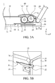
- Figs. 3A and 3B are perspective diagrams of an electronic device with the display in an open position relative to the main body according to an embodiment of the invention.
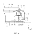
- Fig. 4 is a perspective diagram of a transmission unit according to another embodiment of the invention.
- an embodiment of an electronic device 1 primarily comprises a main body 10, a display 20, a foot pad 30, and a transmission unit 40.
- the display 20 is pivotally connected to a side of the main body 10 and is rotatable relative thereto.
- the foot pad 30 is disposed at an edge on the bottom side of the main body 10, adjacent to the display 20, and protrudes from the bottom surface 11 of the main body 10 to contact a supporting surface G.
- the main body 10 and the foot pad 30 are substantially parallel to the supporting surface G.
- the transmission unit 40 is disposed in the main body 10 and connects the display 20 with the foot pad 30.
- the transmission unit 40 primarily comprises a first gear 41 and a second gear 42.
- the first gear 41 is pivotally connected to the display 20 via the shaft 50
- the second gear 42 is pivotally connected to the main body 10 and engaged with the first gear 41 and a gear rack 31 of the foot pad 30.
- the first gear 41 may comprises metal
- the second gear 42 may comprises plastic, to reduce noise during operation.
- an elastic portion 32 of the foot pad 30 protrudes from the bottom surface 11 of the main body 10, and at least one guiding portion 35 is movably connected to the main body 10, such that the foot pad 30 can move relative to the main body 10 along the Y axis via the guiding portion 35.
- the foot pad 30 when the display 20 is in a closed position relative to the main body 10, the foot pad 30 is hidden and aligned with the back side 12 of the main body 10. Additionally, the elastic portion 32 of the foot pad 30 protrudes from the bottom surface 11 of the main body 10.
- the foot pad 30 primarily comprises a gear rack 31, an elastic portion 32, a shelter portion 33, a flat portion 34, and at least one guiding portion 35.
- the flat portion 34 is formed on the top side of the foot pad 30 and at one end thereof.
- the shelter portion 33 is formed on the top side and at the other end of the foot pad 30 relative to the flat portion 34.
- the shelter portion 33 is thin (along the Z direction) and forms a cantilever structure.
- the gear rack 31 is longitudinally (along the Y direction in Fig. 2 ) formed on the top side of the foot pad 30 between the flat portion 34 and the shelter portion 33.
- the elastic portion 32 is disposed on the bottom side of the foot pad 30, wherein the elastic portion 32 may comprise rubber for better elasticity and friction.
- the two guiding portions 35 are formed on opposite sides of the foot pad 30 and parallel to the XY plane. In some embodiments, the guiding portions 35 are rectangular slots for guiding the foot pad 30 to slide relative to the main body 10.
- the display 20 when the display 20 is rotated from a closed position to an open position relative to the main body 10 (along the clockwise direction as the arrow indicated in Fig. 3A ), the display 20 drives the shaft 50 and the first gear 41 to rotate, and the first gear 41 forces the second gear 42 to rotate in an opposite direction.
- the second gear 42 forces the gear rack 31 and the foot pad 30 to move along a first direction (the Y direction in Fig. 3A ), such that the foot pad 30 protrudes from the rear side 12 of the main body 10 with the flat portion 34 exposed thereto.
- the display 20 may rotate to a predetermined position without obstructing the movement of the foot pad 30.
- the display 20 drives the transmission unit 40 to force the foot pad 30 to retract into the main body 10 along a second direction (the -Y direction in Fig. 3A ) relative to the main body 10.
- a second direction the -Y direction in Fig. 3A
- an opening A is formed between the bottom surface 11 of the main body 10 and the foot pad 30.
- the shelter portion 33 of the foot pad 30 can cover the opening A, to prevent dust from entering into the main body 10.
- the foot pad 30 moves a distance D along the first direction (the Y direction in Fig. 3A ), thus to move the fulcrum of the electronic device 1 to the right.
- the electronic device 1 can be stabilized and prevented from shaking or backward tilting.
- another embodiment of the transmission unit 40 comprises a first gear 41, a rack member 60, and a rotary member 70.
- the first gear 41 is pivotally connected to the display 20 via the shaft 50 and engaged with the rack member 60.
- the rotary member 70 is pivotally connected to the main body 10 by a pivot 73, forming a first arm 71 which is pivotally connected to the rack member 60 and a second arm 72 which is pivotally connected to the foot pad 30, wherein the length of the second arm 72 exceeds that of the first arm 71.
- the rack member 60 pushes the rotary member 70 to force the foot pad 30 to move along the first direction (the Y direction in Fig. 4 ). Since the displacement of the second arm 72 in the Y direction exceeds that of the first arm 71 in the -Y direction during rotation of the rotary member 70, the moved distance of the foot pad 30 can be increased.
- the invention provides an electronic device, comprising a main body, a display pivotally connected thereto, a foot pad disposed on the bottom side of the main body and at the edge thereof, and a transmission unit disposed in the main body.
- the transmission unit may have a rod, cam or gear mechanism, connecting the display with the foot pad.
Landscapes
- Engineering & Computer Science (AREA)
- Computer Hardware Design (AREA)
- Theoretical Computer Science (AREA)
- Physics & Mathematics (AREA)
- Human Computer Interaction (AREA)
- General Engineering & Computer Science (AREA)
- General Physics & Mathematics (AREA)
- Mathematical Physics (AREA)
- Microelectronics & Electronic Packaging (AREA)
- Casings For Electric Apparatus (AREA)
- Calculators And Similar Devices (AREA)
- Devices For Indicating Variable Information By Combining Individual Elements (AREA)
Abstract
Description
- This Application claims priority of Taiwan Patent Application No.
101104288, filed on February 10, 2012 - The application relates in general to an electronic device and in particular to an electronic device having a movable foot pad.
- With rapid progress of touch control technology, notebook computers with touch screens have become popular. Since the notebook computer may be shaken or tilted backward when a user touches the touch screen, it is inconvenient to operate the touch screen. In order to stabilize the notebook computer, a thick pad may be disposed on the bottom side of the notebook computer to prevent shaking or backward tilting thereof. However, this may increase the thickness of the notebook computer and reduce portability thereof.
- An embodiment of the invention provides an electronic device, comprising a main body, a display, a foot pad and a transmission unit. The display is pivotally connected to the main body, and the foot pad is disposed on the bottom side of the main body and contacts a supporting surface parallel thereto. The transmission unit is disposed in the main body and connects the foot pad with the display. When the display rotates from a closed position to an open position relative to the main body, the foot pad moves in a first direction parallel to the supporting surface.
-
Figs. 1A and 1B are perspective diagrams of an electronic device with the display in a closed position relative to the main body according to an embodiment of the invention; -
Fig. 2 is a perspective diagram of a foot pad according to an embodiment of the invention; -
Figs. 3A and 3B are perspective diagrams of an electronic device with the display in an open position relative to the main body according to an embodiment of the invention; and -
Fig. 4 is a perspective diagram of a transmission unit according to another embodiment of the invention; - Referring to
Fig. 1A , an embodiment of anelectronic device 1, such as a notebook computer, primarily comprises amain body 10, adisplay 20, afoot pad 30, and atransmission unit 40. As shown inFig. 1A , thedisplay 20 is pivotally connected to a side of themain body 10 and is rotatable relative thereto. Thefoot pad 30 is disposed at an edge on the bottom side of themain body 10, adjacent to thedisplay 20, and protrudes from thebottom surface 11 of themain body 10 to contact a supporting surface G. Themain body 10 and thefoot pad 30 are substantially parallel to the supporting surface G. Additionally, thetransmission unit 40 is disposed in themain body 10 and connects thedisplay 20 with thefoot pad 30. - In this embodiment, the
transmission unit 40 primarily comprises afirst gear 41 and asecond gear 42. Thefirst gear 41 is pivotally connected to thedisplay 20 via theshaft 50, and thesecond gear 42 is pivotally connected to themain body 10 and engaged with thefirst gear 41 and agear rack 31 of thefoot pad 30. Thefirst gear 41 may comprises metal, and thesecond gear 42 may comprises plastic, to reduce noise during operation. As shown inFig. 1A , anelastic portion 32 of thefoot pad 30 protrudes from thebottom surface 11 of themain body 10, and at least one guidingportion 35 is movably connected to themain body 10, such that thefoot pad 30 can move relative to themain body 10 along the Y axis via the guidingportion 35. - As shown in
Fig. 1B , when thedisplay 20 is in a closed position relative to themain body 10, thefoot pad 30 is hidden and aligned with theback side 12 of themain body 10. Additionally, theelastic portion 32 of thefoot pad 30 protrudes from thebottom surface 11 of themain body 10. - Referring to
Fig. 2 , thefoot pad 30 primarily comprises agear rack 31, anelastic portion 32, ashelter portion 33, aflat portion 34, and at least one guidingportion 35. Theflat portion 34 is formed on the top side of thefoot pad 30 and at one end thereof. Theshelter portion 33 is formed on the top side and at the other end of thefoot pad 30 relative to theflat portion 34. As shown inFig. 2 , theshelter portion 33 is thin (along the Z direction) and forms a cantilever structure. Thegear rack 31 is longitudinally (along the Y direction inFig. 2 ) formed on the top side of thefoot pad 30 between theflat portion 34 and theshelter portion 33. Theelastic portion 32 is disposed on the bottom side of thefoot pad 30, wherein theelastic portion 32 may comprise rubber for better elasticity and friction. The two guidingportions 35 are formed on opposite sides of thefoot pad 30 and parallel to the XY plane. In some embodiments, the guidingportions 35 are rectangular slots for guiding thefoot pad 30 to slide relative to themain body 10. - Referring to
Figs. 3A and 3B , when thedisplay 20 is rotated from a closed position to an open position relative to the main body 10 (along the clockwise direction as the arrow indicated inFig. 3A ), thedisplay 20 drives theshaft 50 and thefirst gear 41 to rotate, and thefirst gear 41 forces thesecond gear 42 to rotate in an opposite direction. Thus, thesecond gear 42 forces thegear rack 31 and thefoot pad 30 to move along a first direction (the Y direction inFig. 3A ), such that thefoot pad 30 protrudes from therear side 12 of themain body 10 with theflat portion 34 exposed thereto. Furthermore, as shown inFig. 3B , thedisplay 20 may rotate to a predetermined position without obstructing the movement of thefoot pad 30. - Specifically, when the
display 20 is rotated from the open position to the closed position relative to themain body 10, thedisplay 20 drives thetransmission unit 40 to force thefoot pad 30 to retract into themain body 10 along a second direction (the -Y direction inFig. 3A ) relative to themain body 10. As shown inFig. 3B , while thefoot pad 30 is to move, an opening A is formed between thebottom surface 11 of themain body 10 and thefoot pad 30. Theshelter portion 33 of thefoot pad 30 can cover the opening A, to prevent dust from entering into themain body 10. It is noted that when thedisplay 20 is rotated from the closed position to the open position relative to themain body 10, thefoot pad 30 moves a distance D along the first direction (the Y direction inFig. 3A ), thus to move the fulcrum of theelectronic device 1 to the right. With the protrudingfoot pad 30, theelectronic device 1 can be stabilized and prevented from shaking or backward tilting. - Referring to
Fig. 4 , another embodiment of thetransmission unit 40 comprises afirst gear 41, arack member 60, and arotary member 70. Thefirst gear 41 is pivotally connected to thedisplay 20 via theshaft 50 and engaged with therack member 60. Therotary member 70 is pivotally connected to themain body 10 by apivot 73, forming afirst arm 71 which is pivotally connected to therack member 60 and asecond arm 72 which is pivotally connected to thefoot pad 30, wherein the length of thesecond arm 72 exceeds that of thefirst arm 71. When thedisplay 20 is rotated from a closed position to the open position, thedisplay 20 drives thefirst gear 41 to rotate in a clockwise direction to force therack member 60 to move along the second direction (the -Y direction inFig. 4 ). Subsequently, therack member 60 pushes therotary member 70 to force thefoot pad 30 to move along the first direction (the Y direction inFig. 4 ). Since the displacement of thesecond arm 72 in the Y direction exceeds that of thefirst arm 71 in the -Y direction during rotation of therotary member 70, the moved distance of thefoot pad 30 can be increased. - The invention provides an electronic device, comprising a main body, a display pivotally connected thereto, a foot pad disposed on the bottom side of the main body and at the edge thereof, and a transmission unit disposed in the main body. The transmission unit may have a rod, cam or gear mechanism, connecting the display with the foot pad. When the display is rotated from a closed position to an open position, the display drives the transmission unit to move the foot pad, and the foot pad protrudes from a rear side of the main body, thereby preventing the electronic device from shaking or backward tilting.
- While the invention has been described by way of example and in terms of preferred embodiment, it is to be understood that the invention is not limited thereto. To the contrary, it is intended to cover various modifications and similar arrangements (as would be apparent to those skilled in the art). Therefore, the scope of the appended claims should be accorded the broadest interpretation to encompass all such modifications and similar arrangements.
Claims (10)
- An electronic device, comprising:a main body;a display, pivotally connected to the main body;a foot pad, disposed on the bottom side of the main body and at the edge thereof, wherein the foot pad contacts a supporting surface and is parallel thereto; anda transmission unit, disposed in the main body and connecting the foot pad with the display;wherein when the display is rotated from a closed position to an open position relative to the main body, the display drives the transmission unit to force the foot pad to move relative to the main body along a first direction, wherein the first direction is parallel to the supporting surface, and when the display is rotated from the open position to the closed position relative to the main body, the display drives the transmission unit to force the foot pad to move relative to the main body along a second direction opposite to the first direction.
- The electronic device as claimed in claim 1, wherein the foot pad comprises a gear rack, and the transmission unit comprises a first gear connected to the display and a second gear connecting the first gear with the gear rack, wherein when the display is rotated from the closed position to the open position, the display rotates and forces the gear rack to move along the first direction via the first gear and the second gear.
- The electronic device as claimed in claim 2, wherein the first gear comprises metal and the second gear comprises plastic.
- The electronic device as claimed in claim 1, wherein the transmission unit comprises a first gear connected to the display, a rack member, and a rotary member pivotally connected to the main body and forming a first arm and a second arm, wherein the first arm is pivotally connected to the rack member, and the second arm is pivotally connected to the foot pad, and when the display is rotated from a closed position to the open position, the display drives the first gear to force the rack member to move along the second direction, wherein the rack member pushes the rotary member to force the foot pad to move along the first direction.
- The electronic device as claimed in claim 4, wherein the length of the second arm exceeds that of the first arm.
- The electronic device as claimed in claim 1, wherein the foot pad comprises an elastic portion connected to the supporting surface.
- The electronic device as claimed in claim 6, wherein the elastic portion comprises rubber.
- The electronic device as claimed in claim 1, wherein the foot pad comprises a shelter portion, and when the foot pad moves relative to the main body along the first direction, an opening is formed between the foot pad and the main body, and the shelter portion covers the opening.
- The electronic device as claimed in claim 1, wherein the foot pad comprises a guiding portion connected to the main body, to guide the foot pad to move relative to the main body along the first direction.
- The electronic device as claimed in claim 1, wherein the transmission unit has a rod, cam or gear mechanism.
Applications Claiming Priority (1)
| Application Number | Priority Date | Filing Date | Title |
|---|---|---|---|
| TW101104288A TWI465884B (en) | 2012-02-10 | 2012-02-10 | Electronic device |
Publications (3)
| Publication Number | Publication Date |
|---|---|
| EP2626766A2 true EP2626766A2 (en) | 2013-08-14 |
| EP2626766A3 EP2626766A3 (en) | 2016-06-15 |
| EP2626766B1 EP2626766B1 (en) | 2018-09-05 |
Family
ID=47561076
Family Applications (1)
| Application Number | Title | Priority Date | Filing Date |
|---|---|---|---|
| EP12195803.7A Not-in-force EP2626766B1 (en) | 2012-02-10 | 2012-12-06 | Electronic device |
Country Status (3)
| Country | Link |
|---|---|
| US (1) | US9042086B2 (en) |
| EP (1) | EP2626766B1 (en) |
| TW (1) | TWI465884B (en) |
Cited By (1)
| Publication number | Priority date | Publication date | Assignee | Title |
|---|---|---|---|---|
| WO2019005347A1 (en) * | 2017-06-27 | 2019-01-03 | Microsoft Technology Licensing, Llc | Systems and methods of lateral torsional resistance in a hinge |
Families Citing this family (19)
| Publication number | Priority date | Publication date | Assignee | Title |
|---|---|---|---|---|
| DE102014221456A1 (en) * | 2014-10-22 | 2016-04-28 | Zf Friedrichshafen Ag | Gear pairing of a gearbox |
| CN105511564A (en) * | 2016-03-02 | 2016-04-20 | 余苏祥 | Laptop with display screen part capable of being automatically locked and adjusted |
| TWI656433B (en) * | 2017-02-08 | 2019-04-11 | 仁寶電腦工業股份有限公司 | Rotary shaft module and electronic device applying the same |
| TWI669597B (en) * | 2018-04-17 | 2019-08-21 | 宏碁股份有限公司 | Laptop computer |
| WO2020112146A1 (en) * | 2018-11-30 | 2020-06-04 | Hewlett-Packard Development Company, L.P. | Biasing members for computing devices |
| CN111427418B (en) * | 2019-01-09 | 2021-11-30 | 宏碁股份有限公司 | Notebook computer |
| TWI742866B (en) * | 2019-10-08 | 2021-10-11 | 仁寶電腦工業股份有限公司 | Electronic device having sliding assembly |
| CN110825190B (en) * | 2019-11-28 | 2024-06-14 | 合肥联宝信息技术有限公司 | Foot pad mechanism and electronic equipment |
| WO2021221662A1 (en) | 2020-04-30 | 2021-11-04 | Hewlett-Packard Development Company, L.P. | Adjusting mechanisms for flexible display panels |
| TWI751907B (en) * | 2021-02-18 | 2022-01-01 | 宏碁股份有限公司 | Portable electronic device |
| CN114415782B (en) * | 2021-12-13 | 2023-12-08 | 苏州三星电子电脑有限公司 | Notebook computer |
| KR20230115822A (en) * | 2022-01-27 | 2023-08-03 | 삼성전자주식회사 | Electronic device including hinge module |
| EP4400938A4 (en) * | 2022-01-27 | 2025-02-26 | Samsung Electronics Co., Ltd. | Electronic device comprising hinge module |
| CN114942669B (en) * | 2022-05-18 | 2023-08-29 | 紫光计算机科技有限公司 | Lifting structure of notebook foot pad |
| CN115617119B (en) * | 2022-09-14 | 2026-02-06 | 深圳宝龙达信息技术股份有限公司 | Adjusting device, control method thereof and electronic equipment |
| TWI870107B (en) * | 2023-02-01 | 2025-01-11 | 仁寶電腦工業股份有限公司 | Electronic device |
| CN116755512A (en) * | 2023-03-27 | 2023-09-15 | 联想(北京)有限公司 | Electronic equipment and state switching method |
| TWI891139B (en) * | 2023-11-30 | 2025-07-21 | 宏碁股份有限公司 | Laptop computer |
| CN119916901B (en) * | 2025-04-02 | 2025-08-19 | 西安荣耀终端有限公司 | Foldable electronic device |
Family Cites Families (24)
| Publication number | Priority date | Publication date | Assignee | Title |
|---|---|---|---|---|
| JPH0637460Y2 (en) * | 1987-03-24 | 1994-09-28 | 株式会社東芝 | Small electronic device |
| US5121521A (en) * | 1990-04-03 | 1992-06-16 | Casio Computer Co., Ltd. | Mechanism for opening and closing an openable apparatus |
| US7298610B2 (en) * | 2003-08-01 | 2007-11-20 | Lg Electronics Inc. | Supporting apparatus for portable computer |
| TWM250204U (en) * | 2003-12-26 | 2004-11-11 | Hon Hai Prec Ind Co Ltd | Adjustable pedestal assembly |
| TWI262242B (en) * | 2004-05-11 | 2006-09-21 | Nifco Inc | Cap opening/closing mechanism |
| US7591045B2 (en) * | 2004-06-29 | 2009-09-22 | E-Lead Electronics Co., Ltd. | Buffer apparatus for a ceiling screen |
| JP4615269B2 (en) * | 2004-08-18 | 2011-01-19 | 株式会社ニフコ | Acceleration / deceleration mechanism and vehicle accessory case equipped with the acceleration / deceleration mechanism |
| TWI263128B (en) * | 2005-02-14 | 2006-10-01 | Asustek Comp Inc | Notebook PC with an adjustable keyboard |
| JP4836114B2 (en) * | 2005-03-15 | 2011-12-14 | アルパイン株式会社 | Monitor device |
| JP2007110346A (en) * | 2005-10-12 | 2007-04-26 | Omron Corp | Coupling mechanism and portable terminal |
| JP4785574B2 (en) * | 2006-03-15 | 2011-10-05 | キヤノン株式会社 | Image forming apparatus and opening / closing mechanism |
| TWI318552B (en) * | 2007-01-18 | 2009-12-11 | Asustek Comp Inc | Foldable electronic apparatus |
| KR101463818B1 (en) * | 2008-05-14 | 2014-11-20 | 엘지전자 주식회사 | Portable terminal |
| TWI382733B (en) * | 2008-08-25 | 2013-01-11 | Htc Corp | Sliding electronic device |
| TWI362209B (en) * | 2008-10-08 | 2012-04-11 | Htc Corp | Portable electronic device |
| US8102675B2 (en) * | 2009-04-15 | 2012-01-24 | Nokia Corporation | Apparatus, method, and computer program for using a driver wheel to provide a plurality of housing configurations |
| US8296906B2 (en) * | 2009-04-28 | 2012-10-30 | Weber Knapp Company | Four bar hinge |
| KR101483030B1 (en) * | 2009-04-30 | 2015-01-26 | 엘지전자 주식회사 | Mobile terminal |
| TWM370279U (en) * | 2009-06-30 | 2009-12-01 | Wistron Corp | Electronic device with height-adjustable padding mechanism and casing with height-adjustable padding mechanism |
| CN102026501B (en) * | 2009-09-17 | 2013-07-24 | 华硕电脑股份有限公司 | Electronic device |
| CN102109005B (en) * | 2009-12-25 | 2013-10-09 | 鸿富锦精密工业(深圳)有限公司 | Hinge structure and electronic device using same |
| US8374658B2 (en) * | 2010-04-26 | 2013-02-12 | Nokia Corporation | Method and apparatus for flat and tilt slide mechanism |
| US8619415B1 (en) * | 2011-03-31 | 2013-12-31 | Google Inc. | Rotatable and extendable display portion of a computing device |
| TWM416976U (en) * | 2011-07-13 | 2011-11-21 | Acer Inc | Collapsible electronic equipment and pivot structure |
-
2012
- 2012-02-10 TW TW101104288A patent/TWI465884B/en not_active IP Right Cessation
- 2012-11-27 US US13/686,307 patent/US9042086B2/en active Active
- 2012-12-06 EP EP12195803.7A patent/EP2626766B1/en not_active Not-in-force
Non-Patent Citations (1)
| Title |
|---|
| None |
Cited By (4)
| Publication number | Priority date | Publication date | Assignee | Title |
|---|---|---|---|---|
| WO2019005347A1 (en) * | 2017-06-27 | 2019-01-03 | Microsoft Technology Licensing, Llc | Systems and methods of lateral torsional resistance in a hinge |
| CN110832432A (en) * | 2017-06-27 | 2020-02-21 | 微软技术许可有限责任公司 | System and method for lateral torsional resistance in a hinge |
| US10606321B2 (en) | 2017-06-27 | 2020-03-31 | Microsoft Technology Licensing, Llc | Systems and methods of lateral torsional resistance in a hinge |
| CN110832432B (en) * | 2017-06-27 | 2023-11-14 | 微软技术许可有限责任公司 | System and method for lateral torsional resistance in a hinge |
Also Published As
| Publication number | Publication date |
|---|---|
| US9042086B2 (en) | 2015-05-26 |
| TWI465884B (en) | 2014-12-21 |
| EP2626766A3 (en) | 2016-06-15 |
| US20130208436A1 (en) | 2013-08-15 |
| TW201333667A (en) | 2013-08-16 |
| EP2626766B1 (en) | 2018-09-05 |
Similar Documents
| Publication | Publication Date | Title |
|---|---|---|
| US9042086B2 (en) | Electronic device with movable foot pad | |
| CN202904430U (en) | Apparatus opening and closing mechanism, and information apparatus | |
| CN102884777B (en) | Method and apparatus for double slider device with tilting display | |
| CN103123524B (en) | Portable computer | |
| US20080174942A1 (en) | Handheld Electronic Device | |
| CN102859978B (en) | For the method and apparatus of level and tilt slide mechanism | |
| CN103123521B (en) | Portable computer | |
| US9317071B2 (en) | Electronic device and hinge module thereof | |
| EP2197182A1 (en) | Handheld electronic device and operating method thereof | |
| US8369076B2 (en) | Electronic device and moving mechanism thereof | |
| US10324495B2 (en) | Base of tablet computer | |
| EP2685344A2 (en) | Collapsible electronic equipment | |
| US9876521B2 (en) | Sliding stand assembly | |
| CN209327901U (en) | Bending structure and flexible screen display equipment | |
| JP5676818B2 (en) | Sliding and tilting tablet computer | |
| US8620396B2 (en) | Slide mechanism and electronic apparatus | |
| CN103257674B (en) | electronic device | |
| CN102340939B (en) | Flip cover type electronic device structure | |
| US8085532B2 (en) | Electronic device | |
| EP2690520A2 (en) | Dampening mechanism and electronic device using same | |
| CN102053663A (en) | Portable computer and keyboard thereof | |
| KR101756141B1 (en) | Slim Type Tilting Hinge and Electric Device having it | |
| JP5874312B2 (en) | Electronics | |
| CN116841351A (en) | Electronic device capable of storing touch control pen | |
| JP2017220323A (en) | Card connector and electronic device |
Legal Events
| Date | Code | Title | Description |
|---|---|---|---|
| PUAI | Public reference made under article 153(3) epc to a published international application that has entered the european phase |
Free format text: ORIGINAL CODE: 0009012 |
|
| AK | Designated contracting states |
Kind code of ref document: A2 Designated state(s): AL AT BE BG CH CY CZ DE DK EE ES FI FR GB GR HR HU IE IS IT LI LT LU LV MC MK MT NL NO PL PT RO RS SE SI SK SM TR |
|
| AX | Request for extension of the european patent |
Extension state: BA ME |
|
| PUAL | Search report despatched |
Free format text: ORIGINAL CODE: 0009013 |
|
| AK | Designated contracting states |
Kind code of ref document: A3 Designated state(s): AL AT BE BG CH CY CZ DE DK EE ES FI FR GB GR HR HU IE IS IT LI LT LU LV MC MK MT NL NO PL PT RO RS SE SI SK SM TR |
|
| AX | Request for extension of the european patent |
Extension state: BA ME |
|
| RIC1 | Information provided on ipc code assigned before grant |
Ipc: G06F 1/16 20060101AFI20160509BHEP |
|
| STAA | Information on the status of an ep patent application or granted ep patent |
Free format text: STATUS: REQUEST FOR EXAMINATION WAS MADE |
|
| 17P | Request for examination filed |
Effective date: 20161026 |
|
| RBV | Designated contracting states (corrected) |
Designated state(s): AL AT BE BG CH CY CZ DE DK EE ES FI FR GB GR HR HU IE IS IT LI LT LU LV MC MK MT NL NO PL PT RO RS SE SI SK SM TR |
|
| STAA | Information on the status of an ep patent application or granted ep patent |
Free format text: STATUS: EXAMINATION IS IN PROGRESS |
|
| 17Q | First examination report despatched |
Effective date: 20170321 |
|
| GRAP | Despatch of communication of intention to grant a patent |
Free format text: ORIGINAL CODE: EPIDOSNIGR1 |
|
| STAA | Information on the status of an ep patent application or granted ep patent |
Free format text: STATUS: GRANT OF PATENT IS INTENDED |
|
| INTG | Intention to grant announced |
Effective date: 20180405 |
|
| GRAS | Grant fee paid |
Free format text: ORIGINAL CODE: EPIDOSNIGR3 |
|
| GRAA | (expected) grant |
Free format text: ORIGINAL CODE: 0009210 |
|
| STAA | Information on the status of an ep patent application or granted ep patent |
Free format text: STATUS: THE PATENT HAS BEEN GRANTED |
|
| AK | Designated contracting states |
Kind code of ref document: B1 Designated state(s): AL AT BE BG CH CY CZ DE DK EE ES FI FR GB GR HR HU IE IS IT LI LT LU LV MC MK MT NL NO PL PT RO RS SE SI SK SM TR |
|
| REG | Reference to a national code |
Ref country code: GB Ref legal event code: FG4D |
|
| REG | Reference to a national code |
Ref country code: CH Ref legal event code: EP |
|
| REG | Reference to a national code |
Ref country code: AT Ref legal event code: REF Ref document number: 1038568 Country of ref document: AT Kind code of ref document: T Effective date: 20180915 |
|
| REG | Reference to a national code |
Ref country code: IE Ref legal event code: FG4D |
|
| REG | Reference to a national code |
Ref country code: DE Ref legal event code: R096 Ref document number: 602012050605 Country of ref document: DE |
|
| REG | Reference to a national code |
Ref country code: NL Ref legal event code: MP Effective date: 20180905 |
|
| REG | Reference to a national code |
Ref country code: LT Ref legal event code: MG4D |
|
| PG25 | Lapsed in a contracting state [announced via postgrant information from national office to epo] |
Ref country code: SE Free format text: LAPSE BECAUSE OF FAILURE TO SUBMIT A TRANSLATION OF THE DESCRIPTION OR TO PAY THE FEE WITHIN THE PRESCRIBED TIME-LIMIT Effective date: 20180905 Ref country code: NO Free format text: LAPSE BECAUSE OF FAILURE TO SUBMIT A TRANSLATION OF THE DESCRIPTION OR TO PAY THE FEE WITHIN THE PRESCRIBED TIME-LIMIT Effective date: 20181205 Ref country code: BG Free format text: LAPSE BECAUSE OF FAILURE TO SUBMIT A TRANSLATION OF THE DESCRIPTION OR TO PAY THE FEE WITHIN THE PRESCRIBED TIME-LIMIT Effective date: 20181205 Ref country code: RS Free format text: LAPSE BECAUSE OF FAILURE TO SUBMIT A TRANSLATION OF THE DESCRIPTION OR TO PAY THE FEE WITHIN THE PRESCRIBED TIME-LIMIT Effective date: 20180905 Ref country code: LT Free format text: LAPSE BECAUSE OF FAILURE TO SUBMIT A TRANSLATION OF THE DESCRIPTION OR TO PAY THE FEE WITHIN THE PRESCRIBED TIME-LIMIT Effective date: 20180905 Ref country code: GR Free format text: LAPSE BECAUSE OF FAILURE TO SUBMIT A TRANSLATION OF THE DESCRIPTION OR TO PAY THE FEE WITHIN THE PRESCRIBED TIME-LIMIT Effective date: 20181206 Ref country code: FI Free format text: LAPSE BECAUSE OF FAILURE TO SUBMIT A TRANSLATION OF THE DESCRIPTION OR TO PAY THE FEE WITHIN THE PRESCRIBED TIME-LIMIT Effective date: 20180905 |
|
| REG | Reference to a national code |
Ref country code: AT Ref legal event code: MK05 Ref document number: 1038568 Country of ref document: AT Kind code of ref document: T Effective date: 20180905 |
|
| PG25 | Lapsed in a contracting state [announced via postgrant information from national office to epo] |
Ref country code: AL Free format text: LAPSE BECAUSE OF FAILURE TO SUBMIT A TRANSLATION OF THE DESCRIPTION OR TO PAY THE FEE WITHIN THE PRESCRIBED TIME-LIMIT Effective date: 20180905 Ref country code: LV Free format text: LAPSE BECAUSE OF FAILURE TO SUBMIT A TRANSLATION OF THE DESCRIPTION OR TO PAY THE FEE WITHIN THE PRESCRIBED TIME-LIMIT Effective date: 20180905 Ref country code: HR Free format text: LAPSE BECAUSE OF FAILURE TO SUBMIT A TRANSLATION OF THE DESCRIPTION OR TO PAY THE FEE WITHIN THE PRESCRIBED TIME-LIMIT Effective date: 20180905 |
|
| PG25 | Lapsed in a contracting state [announced via postgrant information from national office to epo] |
Ref country code: IT Free format text: LAPSE BECAUSE OF FAILURE TO SUBMIT A TRANSLATION OF THE DESCRIPTION OR TO PAY THE FEE WITHIN THE PRESCRIBED TIME-LIMIT Effective date: 20180905 Ref country code: PL Free format text: LAPSE BECAUSE OF FAILURE TO SUBMIT A TRANSLATION OF THE DESCRIPTION OR TO PAY THE FEE WITHIN THE PRESCRIBED TIME-LIMIT Effective date: 20180905 Ref country code: ES Free format text: LAPSE BECAUSE OF FAILURE TO SUBMIT A TRANSLATION OF THE DESCRIPTION OR TO PAY THE FEE WITHIN THE PRESCRIBED TIME-LIMIT Effective date: 20180905 Ref country code: IS Free format text: LAPSE BECAUSE OF FAILURE TO SUBMIT A TRANSLATION OF THE DESCRIPTION OR TO PAY THE FEE WITHIN THE PRESCRIBED TIME-LIMIT Effective date: 20190105 Ref country code: NL Free format text: LAPSE BECAUSE OF FAILURE TO SUBMIT A TRANSLATION OF THE DESCRIPTION OR TO PAY THE FEE WITHIN THE PRESCRIBED TIME-LIMIT Effective date: 20180905 Ref country code: CZ Free format text: LAPSE BECAUSE OF FAILURE TO SUBMIT A TRANSLATION OF THE DESCRIPTION OR TO PAY THE FEE WITHIN THE PRESCRIBED TIME-LIMIT Effective date: 20180905 Ref country code: EE Free format text: LAPSE BECAUSE OF FAILURE TO SUBMIT A TRANSLATION OF THE DESCRIPTION OR TO PAY THE FEE WITHIN THE PRESCRIBED TIME-LIMIT Effective date: 20180905 Ref country code: AT Free format text: LAPSE BECAUSE OF FAILURE TO SUBMIT A TRANSLATION OF THE DESCRIPTION OR TO PAY THE FEE WITHIN THE PRESCRIBED TIME-LIMIT Effective date: 20180905 Ref country code: RO Free format text: LAPSE BECAUSE OF FAILURE TO SUBMIT A TRANSLATION OF THE DESCRIPTION OR TO PAY THE FEE WITHIN THE PRESCRIBED TIME-LIMIT Effective date: 20180905 |
|
| PG25 | Lapsed in a contracting state [announced via postgrant information from national office to epo] |
Ref country code: SM Free format text: LAPSE BECAUSE OF FAILURE TO SUBMIT A TRANSLATION OF THE DESCRIPTION OR TO PAY THE FEE WITHIN THE PRESCRIBED TIME-LIMIT Effective date: 20180905 Ref country code: PT Free format text: LAPSE BECAUSE OF FAILURE TO SUBMIT A TRANSLATION OF THE DESCRIPTION OR TO PAY THE FEE WITHIN THE PRESCRIBED TIME-LIMIT Effective date: 20190105 Ref country code: SK Free format text: LAPSE BECAUSE OF FAILURE TO SUBMIT A TRANSLATION OF THE DESCRIPTION OR TO PAY THE FEE WITHIN THE PRESCRIBED TIME-LIMIT Effective date: 20180905 |
|
| REG | Reference to a national code |
Ref country code: DE Ref legal event code: R097 Ref document number: 602012050605 Country of ref document: DE |
|
| PLBE | No opposition filed within time limit |
Free format text: ORIGINAL CODE: 0009261 |
|
| STAA | Information on the status of an ep patent application or granted ep patent |
Free format text: STATUS: NO OPPOSITION FILED WITHIN TIME LIMIT |
|
| PG25 | Lapsed in a contracting state [announced via postgrant information from national office to epo] |
Ref country code: DK Free format text: LAPSE BECAUSE OF FAILURE TO SUBMIT A TRANSLATION OF THE DESCRIPTION OR TO PAY THE FEE WITHIN THE PRESCRIBED TIME-LIMIT Effective date: 20180905 |
|
| REG | Reference to a national code |
Ref country code: CH Ref legal event code: PL |
|
| 26N | No opposition filed |
Effective date: 20190606 |
|
| PG25 | Lapsed in a contracting state [announced via postgrant information from national office to epo] |
Ref country code: MC Free format text: LAPSE BECAUSE OF FAILURE TO SUBMIT A TRANSLATION OF THE DESCRIPTION OR TO PAY THE FEE WITHIN THE PRESCRIBED TIME-LIMIT Effective date: 20180905 Ref country code: LU Free format text: LAPSE BECAUSE OF NON-PAYMENT OF DUE FEES Effective date: 20181206 Ref country code: SI Free format text: LAPSE BECAUSE OF FAILURE TO SUBMIT A TRANSLATION OF THE DESCRIPTION OR TO PAY THE FEE WITHIN THE PRESCRIBED TIME-LIMIT Effective date: 20180905 |
|
| REG | Reference to a national code |
Ref country code: IE Ref legal event code: MM4A |
|
| REG | Reference to a national code |
Ref country code: BE Ref legal event code: MM Effective date: 20181231 |
|
| PG25 | Lapsed in a contracting state [announced via postgrant information from national office to epo] |
Ref country code: IE Free format text: LAPSE BECAUSE OF NON-PAYMENT OF DUE FEES Effective date: 20181206 |
|
| PG25 | Lapsed in a contracting state [announced via postgrant information from national office to epo] |
Ref country code: BE Free format text: LAPSE BECAUSE OF NON-PAYMENT OF DUE FEES Effective date: 20181231 |
|
| PG25 | Lapsed in a contracting state [announced via postgrant information from national office to epo] |
Ref country code: CH Free format text: LAPSE BECAUSE OF NON-PAYMENT OF DUE FEES Effective date: 20181231 Ref country code: LI Free format text: LAPSE BECAUSE OF NON-PAYMENT OF DUE FEES Effective date: 20181231 |
|
| PG25 | Lapsed in a contracting state [announced via postgrant information from national office to epo] |
Ref country code: MT Free format text: LAPSE BECAUSE OF NON-PAYMENT OF DUE FEES Effective date: 20181206 |
|
| PG25 | Lapsed in a contracting state [announced via postgrant information from national office to epo] |
Ref country code: TR Free format text: LAPSE BECAUSE OF FAILURE TO SUBMIT A TRANSLATION OF THE DESCRIPTION OR TO PAY THE FEE WITHIN THE PRESCRIBED TIME-LIMIT Effective date: 20180905 |
|
| PG25 | Lapsed in a contracting state [announced via postgrant information from national office to epo] |
Ref country code: HU Free format text: LAPSE BECAUSE OF FAILURE TO SUBMIT A TRANSLATION OF THE DESCRIPTION OR TO PAY THE FEE WITHIN THE PRESCRIBED TIME-LIMIT; INVALID AB INITIO Effective date: 20121206 Ref country code: CY Free format text: LAPSE BECAUSE OF FAILURE TO SUBMIT A TRANSLATION OF THE DESCRIPTION OR TO PAY THE FEE WITHIN THE PRESCRIBED TIME-LIMIT Effective date: 20180905 Ref country code: MK Free format text: LAPSE BECAUSE OF NON-PAYMENT OF DUE FEES Effective date: 20180905 |
|
| PGFP | Annual fee paid to national office [announced via postgrant information from national office to epo] |
Ref country code: GB Payment date: 20231109 Year of fee payment: 12 |
|
| PGFP | Annual fee paid to national office [announced via postgrant information from national office to epo] |
Ref country code: FR Payment date: 20231108 Year of fee payment: 12 Ref country code: DE Payment date: 20231107 Year of fee payment: 12 |
|
| REG | Reference to a national code |
Ref country code: DE Ref legal event code: R119 Ref document number: 602012050605 Country of ref document: DE |
|
| GBPC | Gb: european patent ceased through non-payment of renewal fee |
Effective date: 20241206 |
|
| PG25 | Lapsed in a contracting state [announced via postgrant information from national office to epo] |
Ref country code: DE Free format text: LAPSE BECAUSE OF NON-PAYMENT OF DUE FEES Effective date: 20250701 |
|
| PG25 | Lapsed in a contracting state [announced via postgrant information from national office to epo] |
Ref country code: GB Free format text: LAPSE BECAUSE OF NON-PAYMENT OF DUE FEES Effective date: 20241206 |
|
| PG25 | Lapsed in a contracting state [announced via postgrant information from national office to epo] |
Ref country code: FR Free format text: LAPSE BECAUSE OF NON-PAYMENT OF DUE FEES Effective date: 20241231 |