EP2626750A1 - Developer case and image forming apparatus to which developer case is applied - Google Patents
Developer case and image forming apparatus to which developer case is applied Download PDFInfo
- Publication number
- EP2626750A1 EP2626750A1 EP13167141.4A EP13167141A EP2626750A1 EP 2626750 A1 EP2626750 A1 EP 2626750A1 EP 13167141 A EP13167141 A EP 13167141A EP 2626750 A1 EP2626750 A1 EP 2626750A1
- Authority
- EP
- European Patent Office
- Prior art keywords
- toner
- developer
- rotating shaft
- main body
- cylindrical portion
- Prior art date
- Legal status (The legal status is an assumption and is not a legal conclusion. Google has not performed a legal analysis and makes no representation as to the accuracy of the status listed.)
- Granted
Links
Images









Classifications
-
- G—PHYSICS
- G03—PHOTOGRAPHY; CINEMATOGRAPHY; ANALOGOUS TECHNIQUES USING WAVES OTHER THAN OPTICAL WAVES; ELECTROGRAPHY; HOLOGRAPHY
- G03G—ELECTROGRAPHY; ELECTROPHOTOGRAPHY; MAGNETOGRAPHY
- G03G15/00—Apparatus for electrographic processes using a charge pattern
- G03G15/06—Apparatus for electrographic processes using a charge pattern for developing
- G03G15/08—Apparatus for electrographic processes using a charge pattern for developing using a solid developer, e.g. powder developer
- G03G15/0896—Arrangements or disposition of the complete developer unit or parts thereof not provided for by groups G03G15/08 - G03G15/0894
-
- G—PHYSICS
- G03—PHOTOGRAPHY; CINEMATOGRAPHY; ANALOGOUS TECHNIQUES USING WAVES OTHER THAN OPTICAL WAVES; ELECTROGRAPHY; HOLOGRAPHY
- G03G—ELECTROGRAPHY; ELECTROPHOTOGRAPHY; MAGNETOGRAPHY
- G03G15/00—Apparatus for electrographic processes using a charge pattern
- G03G15/06—Apparatus for electrographic processes using a charge pattern for developing
- G03G15/08—Apparatus for electrographic processes using a charge pattern for developing using a solid developer, e.g. powder developer
- G03G15/0822—Arrangements for preparing, mixing, supplying or dispensing developer
- G03G15/0865—Arrangements for supplying new developer
- G03G15/0875—Arrangements for supplying new developer cartridges having a box like shape
-
- G—PHYSICS
- G03—PHOTOGRAPHY; CINEMATOGRAPHY; ANALOGOUS TECHNIQUES USING WAVES OTHER THAN OPTICAL WAVES; ELECTROGRAPHY; HOLOGRAPHY
- G03G—ELECTROGRAPHY; ELECTROPHOTOGRAPHY; MAGNETOGRAPHY
- G03G15/00—Apparatus for electrographic processes using a charge pattern
- G03G15/06—Apparatus for electrographic processes using a charge pattern for developing
- G03G15/08—Apparatus for electrographic processes using a charge pattern for developing using a solid developer, e.g. powder developer
- G03G15/0822—Arrangements for preparing, mixing, supplying or dispensing developer
- G03G15/0877—Arrangements for metering and dispensing developer from a developer cartridge into the development unit
-
- G—PHYSICS
- G03—PHOTOGRAPHY; CINEMATOGRAPHY; ANALOGOUS TECHNIQUES USING WAVES OTHER THAN OPTICAL WAVES; ELECTROGRAPHY; HOLOGRAPHY
- G03G—ELECTROGRAPHY; ELECTROPHOTOGRAPHY; MAGNETOGRAPHY
- G03G15/00—Apparatus for electrographic processes using a charge pattern
- G03G15/06—Apparatus for electrographic processes using a charge pattern for developing
- G03G15/08—Apparatus for electrographic processes using a charge pattern for developing using a solid developer, e.g. powder developer
- G03G15/0822—Arrangements for preparing, mixing, supplying or dispensing developer
- G03G15/0877—Arrangements for metering and dispensing developer from a developer cartridge into the development unit
- G03G15/0879—Arrangements for metering and dispensing developer from a developer cartridge into the development unit for dispensing developer from a developer cartridge not directly attached to the development unit
-
- G—PHYSICS
- G03—PHOTOGRAPHY; CINEMATOGRAPHY; ANALOGOUS TECHNIQUES USING WAVES OTHER THAN OPTICAL WAVES; ELECTROGRAPHY; HOLOGRAPHY
- G03G—ELECTROGRAPHY; ELECTROPHOTOGRAPHY; MAGNETOGRAPHY
- G03G15/00—Apparatus for electrographic processes using a charge pattern
- G03G15/06—Apparatus for electrographic processes using a charge pattern for developing
- G03G15/08—Apparatus for electrographic processes using a charge pattern for developing using a solid developer, e.g. powder developer
- G03G15/0822—Arrangements for preparing, mixing, supplying or dispensing developer
- G03G15/0887—Arrangements for conveying and conditioning developer in the developing unit, e.g. agitating, removing impurities or humidity
- G03G15/0889—Arrangements for conveying and conditioning developer in the developing unit, e.g. agitating, removing impurities or humidity for agitation or stirring
-
- G—PHYSICS
- G03—PHOTOGRAPHY; CINEMATOGRAPHY; ANALOGOUS TECHNIQUES USING WAVES OTHER THAN OPTICAL WAVES; ELECTROGRAPHY; HOLOGRAPHY
- G03G—ELECTROGRAPHY; ELECTROPHOTOGRAPHY; MAGNETOGRAPHY
- G03G15/00—Apparatus for electrographic processes using a charge pattern
- G03G15/06—Apparatus for electrographic processes using a charge pattern for developing
- G03G15/08—Apparatus for electrographic processes using a charge pattern for developing using a solid developer, e.g. powder developer
- G03G15/0822—Arrangements for preparing, mixing, supplying or dispensing developer
- G03G15/0887—Arrangements for conveying and conditioning developer in the developing unit, e.g. agitating, removing impurities or humidity
- G03G15/0891—Arrangements for conveying and conditioning developer in the developing unit, e.g. agitating, removing impurities or humidity for conveying or circulating developer, e.g. augers
-
- G—PHYSICS
- G03—PHOTOGRAPHY; CINEMATOGRAPHY; ANALOGOUS TECHNIQUES USING WAVES OTHER THAN OPTICAL WAVES; ELECTROGRAPHY; HOLOGRAPHY
- G03G—ELECTROGRAPHY; ELECTROPHOTOGRAPHY; MAGNETOGRAPHY
- G03G15/00—Apparatus for electrographic processes using a charge pattern
- G03G15/06—Apparatus for electrographic processes using a charge pattern for developing
- G03G15/08—Apparatus for electrographic processes using a charge pattern for developing using a solid developer, e.g. powder developer
- G03G15/0822—Arrangements for preparing, mixing, supplying or dispensing developer
- G03G15/0887—Arrangements for conveying and conditioning developer in the developing unit, e.g. agitating, removing impurities or humidity
- G03G15/0891—Arrangements for conveying and conditioning developer in the developing unit, e.g. agitating, removing impurities or humidity for conveying or circulating developer, e.g. augers
- G03G15/0893—Arrangements for conveying and conditioning developer in the developing unit, e.g. agitating, removing impurities or humidity for conveying or circulating developer, e.g. augers in a closed loop within the sump of the developing device
Definitions
- the image forming portion 30 performs an image forming process, and more specifically, forms a toner image on a sheet sent out from the paper feed portion 20.
- the image forming portion 30 includes a photosensitive drum 31 (image bearing member), and a charging unit 32, an exposing unit (not shown in Fig. 1 ), a developing unit 33, a transfer roller 34, and a cleaning unit 35 that are positioned around the photosensitive drum 31.
- the cylindrical portion 52 includes a discharge port 521, and the cylindrical portion 52 is attached to the developing unit 33.
- the discharge port 521 is a drop opening located in the bottom portion 525 (lower surface) of the cylindrical portion 52.
- An engaging portion 526 that engages with part of the housing 60 at the time of the above-described attachment is disposed on the bottom portion 525.
- Toner stored in the main body 51 is sent out to the cylindrical portion 52 by rotationally driving a rotating unit 54 (described later) and is discharged through the discharge port 521.
- the cylindrical portion 52 has an inner wall surface that is circular in cross-section and corresponds to the rotation locus of the most radially extending part of the rotating unit 54 (second transport member 56).
- FIG. 15 is a schematic sectional side view of a toner container 50, for illustrating the toner transport operation by the rotating unit 54 of Fig. 10 .
- the toner transport operation by the first transport member 55 and the second transport member 56 is the same as the operation described with reference to Fig. 13 and Fig. 14 .
- the surface of toner is highest at the cylindrical portion 52 side end of the main body 51 and slopes downwardly as shown in Fig. 20A .
- the toner container 50E when the amount of toner remaining in the container is small, the surface of toner is flat in the part of the main body 51 close to the cylindrical portion 52 as shown in Fig. 21 . This is caused by the fact that in the part close to the cylindrical portion 52, the pressing force exerted on toner by the second transport member 56 is relatively weak.
- the pressing force exerted on toner by the second transport member 56 reaches the vicinity of the cylindrical portion 52.
- the distance D2 be greater than the thickness D1. Since the distance D2 is greater than the thickness D1, a sufficient space exists between the outermost circumferential part 55A of the spiral of the first transport member 55 and the radially inner surface 57A of the pair of dispersing members 57. Thus, the region where toner is transported by the first transport member 55 is secured in the inside of the spiral of the second transport member 56. Thus, toner can be reliably transported in the first transport direction by the first transport member 55.
Landscapes
- Physics & Mathematics (AREA)
- General Physics & Mathematics (AREA)
- Dry Development In Electrophotography (AREA)
Abstract
Description
- The present disclosure relates to a developer case for storing developer, and an image forming apparatus to which the developer case is attached.
- In an image forming apparatus, that forms an image on a sheet using toner (developer), a developer case such as a toner container is necessary. A toner container stores toner to be supplied to a developing unit, and is detachably attached to an image forming apparatus. In general, a toner container has a main body that serves as a storage space for toner, a discharge port located in the bottom wall of the main body, a transport screw that transports toner toward the discharge port, and an agitating paddle that moves toner in the main body. The spiral of the transport screw has a double spiral structure consisting of a radially inner spiral and a radially outer spiral.
- One of the important considerations in a toner container is to discharge toner through the discharge port such that no toner remains in the main body. However, the shape of a toner container is determined based not only on the ease of toner discharge, but also the design of the image forming apparatus. Hence, depending on the shape of a container, toner can become packed in the vicinity of the discharge port, and the discharge of toner hindered.
- A developer case according to an embodiment of the present invention is provided that includes a main body, a cylindrical portion, and a rotating unit. The main body has a bottom wall and contains developer. The cylindrical portion connects to the bottom wall, protrudes from the main body, and has a discharge port. The rotating unit is positioned so as to extend across the main body and the cylindrical portion, transports the developer in the main body, has a rotating shaft, a first transport member, a second transport member, and dispersing members. The rotating shaft extends in the direction in which the bottom wall extends and has a first portion located in the main body and a second portion located in the cylindrical portion. The first transport member is located on the circumferential surface of the second portion of the rotating shaft, rotates integrally with the rotating shaft, and transports the developer in a first transport direction from the cylindrical portion to the main body. The second transport member is positioned over the circumferential surface of the first portion of the rotating shaft and on the radially outer side of the first transport member, rotates integrally with the rotating shaft, and transports the developer in a second transport direction from the main body to the cylindrical portion. The dispersing members extend parallel to the rotating shaft and across the first portion and the second portion and disperse the developer in the radial direction.
- An image forming apparatus according to an embodiment of the present invention is provided that includes an image bearing member that bears a developer image on the circumferential surface thereof, a developing unit that supplies developer to the image bearing member, and the above-described developer case according to an embodiment of the present invention, the developer case being detachably connected to the developing unit and supplying the developer to the developing unit.
- A developer case according to another embodiment of the present invention is provided that includes a main body, a cylindrical portion, and a rotating unit. The main body has a bottom wall and contains developer. The cylindrical portion connects to the bottom wall, protrudes from the main body, and has a discharge port. The rotating unit is positioned so as to extend across the main body and the cylindrical portion, transports the developer in the main body, has a rotating shaft, a first transport member, and a second transport member. The rotating shaft extends in a direction in which the bottom wall extends. The first transport member is located on the circumferential surface of the rotating shaft, rotates integrally with the rotating shaft, and transports the developer in a first transport direction from the cylindrical portion to the main body. The second transport member is located over the circumferential surface of the rotating shaft and on the radially outer side of the first transport member, rotates integrally with the rotating shaft, and transports the developer in a second transport direction from the main body to the cylindrical portion. The cylindrical portion has an inner wall surface that is circular in cross-seetion and corresponds to the rotation locus of the most radially extending part of the second transport member.
- An image forming apparatus according to another embodiment of the present invention is provided that includes an image bearing member that bears a developer image on the circumferential surface thereof, a developing unit that supplies developer to the image bearing member, and the above-described developer case according to another embodiment of the present invention, the developer case being detachably connected to the developing unit and supplying the developer to the developing unit.
- Additional features and advantages are described herein, and will be apparent from the following Detailed Description and the figures.
-
-
Fig. 1 is a sectional view showing the internal structure of an image forming apparatus according to an embodiment of the present invention; -
Fig. 2 is a plan view showing a developing unit and a toner container incorporated in the image forming apparatus; -
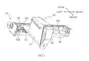
Fig. 3 is a perspective view of the developing unit and the toner container shown inFig. 2 ; -
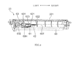
Fig. 4 is a perspective view of the developing unit alone; -
Fig. 5 is a plan view showing the internal structure of the developing unit; -
Fig. 6 is a perspective view of a toner container in an embodiment; -
Fig. 7 is a perspective view of the toner container from the direction opposite that ofFig. 6 ; -
Fig. 8 is a side view of the toner container; -
Fig. 9 is a sectional side view of the toner container; -
Fig. 10 is a perspective view of a rotating unit located in the toner container; -
Fig. 11 is a partial sectional view of the rotating unit; -
Fig. 12 is a perspective view showing a rotating unit according to another embodiment; -
Fig. 13 is a schematic sectional side view of a toner container, illustrating the toner transport operation by the rotating unit; -
Fig. 14 is a schematic sectional side view of the toner container with the rotating unit rotated 90 degrees with respect toFig. 13 ; -
Fig. 15 is a schematic sectional side view of a toner container, illustrating the toner transport operation by a rotating unit; -
Fig. 16 is a schematic sectional side view of the toner container, illustrating a preferable angle of the spiral; -
Fig. 17 is a graph evaluating the return of toner from the cylindrical portion to the main body; -
Fig. 18 is a schematic sectional side view of a toner container having a rotating unit according to another embodiment; -
Fig. 19 is a schematic sectional side view of a toner container, showing another embodiment of a film; -
Figs. 20A and 20B are schematic sectional views of a toner container, showing another embodiment having a toner sensor; -
Fig. 21 is a schematic sectional side view of a toner container, showing another embodiment having a toner sensor; -
Fig. 22 is a graph showing the sensitivities of the toner sensors ofFig. 20 andFig. 21 ; -
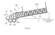
Fig. 23 is a schematic sectional side view of a toner container, showing another embodiment in which a toner container is connected to the developing unit at an angle; -
Fig. 24 is a sectional side view of a toner container in another embodiment; -
Fig. 25 is a perspective view of a rotating unit disposed in the toner container; -
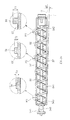
Fig. 26 is a side view of the rotating unit with accompanying partial sectional views; -
Fig. 27 is a schematic sectional side view of the toner container, illustrating how toner is moved by the rotating unit; -
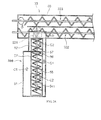
Fig. 28 is a schematic horizontal sectional view of the toner container and the developing unit, illustrating how toner is moved by the rotating unit; and -
Fig. 29 is a partial sectional view of the rotating unit, showing an example of the rotating unit. - Embodiments of the present invention will now be described in detail with reference to the drawings.
Fig. 1 is a sectional view showing the internal structure of animage forming apparatus 1 according to an embodiment of the present invention. Although a monochrome printer will be used as an example of animage forming apparatus 1, other examples of image forming apparatus include a copying machine, a facsimile machine, a multifunction device having the functions of these, and an image forming apparatus that forms a color image. - The
image forming apparatus 1 includes amain body housing 10 having a substantially rectangular parallelepiped housing structure, and apaper feed portion 20, animage forming portion 30, a fixingportion 40, and a toner container 50 (developer case) contained in themain body housing 10. - A
front cover 11 is located on the front side (the right side ofFig. 1 ) of themain body housing 10. Arear cover 12 is located on the rear side of themain body housing 10. By opening thefront cover 11, the user can take out thetoner container 50 from the front side of themain body housing 10 when theimage forming apparatus 1 is out of toner (developer). Therear cover 12 is a cover that is opened to remove paper jams or perform maintenance. By opening therear cover 12, the user can take out theimage forming portion 30 and the fixingportion 40 from the rear of themain body housing 10. On the upper surface of themain body housing 10, apaper ejection portion 13, onto which sheets after image formation are ejected, is located. - The
paper feed portion 20 includes apaper cassette 21 that contains sheets undergoing an image forming process. Part of thepaper cassette 21 extends from the front of themain body housing 10. Thepaper cassette 21 includes a sheet containing space in which a stack of the sheets is contained, and a lift plate lifting up the stack of sheets for paper feeding. A sheet sending-outportion 21A is located above the rear end of thepaper cassette 21. In the sheet sending-outportion 21A, a pickup roller (not shown) for sending out the sheets in the uppermost layer of the stack of sheets in thepaper cassette 21 one at a time, is located. - The
image forming portion 30 performs an image forming process, and more specifically, forms a toner image on a sheet sent out from thepaper feed portion 20. Theimage forming portion 30 includes a photosensitive drum 31 (image bearing member), and a chargingunit 32, an exposing unit (not shown inFig. 1 ), a developingunit 33, atransfer roller 34, and acleaning unit 35 that are positioned around the photosensitive drum 31. - The photosensitive drum 31 rotates about its axis, and an electrostatic latent image and a toner image (developer image) is formed on the circumferential surface thereof. For example, a photosensitive drum formed of an amorphous silicon (a-Si) material is used as the photosensitive drum 31. The charging
unit 32 uniformly charges the surface of the photosensitive drum 31 and includes a charging roller in contact with the photosensitive drum 31. The exposing unit has a laser light source and optical system devices, such as mirrors and lenses, and irradiates the circumferential surface of the photosensitive drum 31 with light modulated based on the image data provided by an external device such as a personal computer, thereby forming an electrostatic latent image. - The developing
unit 33 supplies toner to the circumferential surface of the photosensitive drum 31 in order to develop the electrostatic latent image on the photosensitive drum 31 and form a toner image. The developingunit 33 includes a developingroller 331 that includes toner to be supplied to the photosensitive drum 31 and afirst transport screw 332 andsecond transport screw 333 that circulate and transport developer while agitating it in a housing 60 (seeFig. 2 to Fig. 5 ). The developingunit 33 will be described hereinafter. - The
transfer roller 34 transfers a toner image formed on the circumferential surface of the photosensitive drum 31 to a sheet. Thetransfer roller 34 and the photosensitive drum 31 form a transfer nip portion therebetween. A transfer bias of opposite polarity to toner is applied to thetransfer roller 34. Thecleaning unit 35 has a cleaning roller or the like, and cleans the circumferential surface of the photosensitive drum 31 after the transfer of the toner image. - The fixing
portion 40 fixes the transferred toner image to the sheet. The fixingportion 40 includes a fixingroller 41 that has a heat source therein, and apressure roller 42 that is pressed against the fixingroller 41. The fixingroller 41 and thepressure roller 42 form a fixing nip portion therebetween. When the sheet to which the toner image is transferred passes through the fixing nip portion, the toner image is fixed to the sheet by being heated by the fixingroller 41 and being pressed by thepressure roller 42. - Toner to be supplied to the developing
unit 33 is stored in thetoner container 50. Thetoner container 50 includes amain body 51, in which toner is stored, acylindrical portion 52 extending from the lower part of one side surface (the rear surface inFig. 1 ) of themain body 51, alid member 53 that covers another side surface of themain body 51, and arotating unit 54 that is contained in the container and transports toner. By rotationally driving the rotatingunit 54, toner stored in thetoner container 50 is supplied to the inside of the developingunit 33 through adischarge port 521 located in the lower surface of the distal end of thecylindrical portion 52. Thetoner container 50 will be described hereinafter with reference toFig. 6 to Fig. 29 . - In the
main body housing 10, amain transport path 22F and areverse transport path 22B are provided in order to transport sheets. Themain transport path 22F extends from the sheet sending-outportion 21A of thepaper feed portion 20 through theimage forming portion 30 and the fixingportion 40 to a paper ejection opening 14 located opposite to thepaper ejection portion 13 on the upper surface of themain body housing 10. Thereverse transport path 22B is a transport path for returning a sheet that has undergone one-side printing to the upstream side of theimage forming portion 30 in themain transport path 22F, and is used when duplex printing is performed on a sheet. - A
registration roller pair 23 is located upstream of the transfer nip portion between the photosensitive drum 31 and thetransfer roller 34 in themain transport path 22F. The sheet is temporarily stopped by theregistration roller pair 23, undergoes skew correction, and is then sent out to the transfer nip portion at a predetermined timing for image transfer. At appropriate positions in themain transport path 22F and thereverse transport path 22B, a plurality of transport rollers for transporting sheets are disposed. For example, in the vicinity of the paper ejection opening 14, a paperejection roller pair 24 is disposed. - The
reverse transport path 22B is formed between the outer surface of a reversingunit 25 and the inner surface of therear cover 12 of themain body housing 10. On the inner surface of the reversingunit 25, thetransfer roller 34 and one of theregistration roller pair 23 are mounted. Therear cover 12 and the reversingunit 25 are each rotatable about the axis of afulcrum portion 121 provided at the lower ends thereof. If a sheet jams in thereverse transport path 22B, therear cover 12 is opened. If a sheet jams in themain transport path 22F, or when the unit of the photosensitive drum 31 and/or the developingunit 33 is taken out, therear cover 12 and the reversingunit 25 are opened. - Next, with reference to
Fig. 2 to Fig. 7 , the structure of the developingunit 33 and thetoner container 50 and the positional relationship therebetween will be described.Fig. 2 is a plan view showing the developingunit 33 and thetoner container 50 in a mounted state.Fig. 3 is a perspective view of same.Fig. 4 is a perspective view of the developingunit 33 alone.Fig. 5 is a plan view showing the internal structure of the developingunit 33.Fig. 6 andFig. 7 are perspective views of the toner container alone. - The developing
unit 33 comprises ahousing 60 having a box shape that is elongate in one direction (the axial direction of the developing roller 331). Thehousing 60 has an opening extending in its longitudinal direction. Part of the circumferential surface of the developingroller 331 is exposed in this opening. In this embodiment, thehousing 60 is mounted in themain body housing 10 such that its longitudinal direction corresponds to the left-right direction (first direction) of themain body housing 10. - In the
top plate 60T near the left end of thehousing 60, atoner replenishment opening 60H for introducing toner supplied from thetoner container 50 into the housing is located. The developingunit 33 and thetoner container 50 are mounted such that thetoner replenishment opening 60H is located directly below thedischarge port 521 of thetoner container 50. As shown by arrow A inFig. 2 , thetoner container 50 is connected to and detached from the developingunit 33 in a direction perpendicular to the longitudinal direction of the housing 60 (front-rear direction/second direction). Thetoner container 50 has a housing shape that is elongate in one direction in top view. Thus, when thetoner container 50 is connected to the developingunit 33, they form a substantially L-shaped structure in top view (seeFig. 2 ). - On the upper surface of the
top plate 60T, a developingshutter plate 61 is disposed that can slide in the left-right direction. The developingshutter plate 61 is always urged leftward by an urgingspring 62. The urgingspring 62 is a coil spring. One end of the urgingspring 62 is attached to aspring seat 621 located on the right end edge of the developingshutter plate 61, and the other end thereof is attached to aspring seat 622 located on a rib adjacent to the developingshutter plate 61. Although inFig. 4 thetoner replenishment opening 60H is open, when thetoner container 50 is not connected, the developingshutter plate 61 is located on the left by being urged by the urgingspring 62 and covers thetoner replenishment opening 60H. - A
pressing plate 522 is attached to the lower part of the distal end (second end portion 524) of thecylindrical portion 52 of thetoner container 50. Acontainer gear 54G for inputting a rotational drive force into the rotatingunit 54 is exposed on the distal end surface of thecylindrical portion 52. In the back left part of thetoner replenishment opening 60H of thehousing 60, agear holder 63 having aninput gear 631 and acoupling 632 is located. A rotational drive force from a motor (not shown) provided in themain body housing 10 is applied to thecoupling 632. When thetoner container 50 is connected to the developingunit 33, theinput gear 631 meshes with thecontainer gear 54G and transmits the rotational drive force to thecontainer gear 54G. - When the
toner container 50 is connected to the developingunit 33, thecylindrical portion 52 of thetoner container 50 approaches thetoner replenishment opening 60H from the front. At this time, thepressing plate 522 of thetoner container 50 interferes with the developingshutter plate 61 covering thetoner replenishment opening 60H and moves the developingshutter plate 61 to the right. Specifically, anoblique ridge 623 located on the upper substrate of the developingshutter plate 61 interferes with thepressing plate 522, and the developingshutter plate 61 is pushed to the right against the urging force of the urgingspring 62. When thecylindrical portion 52 of thetoner container 50 reaches a predetermined position, thetoner replenishment opening 60H is completely opened, and thecontainer gear 54G meshes with theinput gear 631. - As shown in
Fig. 5 , thehousing 60 has aninternal space 600. In a two-component development system, theinternal space 600 is filled with a developer consisting of toner and carrier. In theinternal space 600, carrier is mixed with toner by agitation, charges toner, and transports toner to the developingroller 331. Toner is successively supplied to the developingroller 331 and consumed, and the same amount of toner as the toner consumed is appropriately supplied from thetoner container 50. - The
internal space 600 of thehousing 60 is partitioned by apartition plate 601 extending in the left-right direction into afirst path 602 and asecond path 603 that are elongate in the left-right direction. Thepartition plate 601 is shorter than the width of thehousing 60 in the left-right direction. At the right end and left end of thepartition plate 601, afirst communication portion 604 and asecond communication portion 605 that connect thefirst path 602 and thesecond path 603 are provided. Thus, a circulation route consisting of thefirst path 602, thefirst communication portion 604, thesecond path 603, and thesecond communication portion 605 is formed in thehousing 60. - The
toner replenishment opening 60H is located over the vicinity of the left end of thefirst path 602. Afirst transport screw 332 is contained in thefirst path 602, and asecond transport screw 333 is contained in thesecond path 603. The first and second transport screws 332 and 333 each include a shaft and a spiral blade extending from the circumference of this shaft. Thefirst transport screw 332 is rotationally driven about its shaft and thereby transports developer in the direction of arrow a inFig. 5 . Thesecond transport screw 333 is rotationally driven about its shaft and thereby transports developer in the direction of arrow b. - By rotationally driving the first and second transport screws 332 and 333, developer is circulated and transported along the above-described circulation route. Toner newly replenished through the
toner replenishment opening 60H will be described. The toner falls into thefirst path 602, is mixed with existing developer, and is transported by thefirst transport screw 332 in the direction of arrow a. At this time, toner is mixed with carrier and charged. Next, toner enters thesecond path 603 from the downstream end of thefirst path 602 through thefirst communication portion 604, and is transported by thesecond transport screw 333 in the direction of arrow b. During this transportation, toner is charged in the same manner, and part of the toner is supplied to the circumferential surface of the developingroller 331. The remaining toner and carrier are returned through thesecond communication portion 605 to the upstream end of thefirst path 602. Although in this embodiment, a developing unit that uses a two-component development system is described, other development systems, such as a one-component development system, may be used. - Next, with reference to
Fig. 6 to Fig. 11 , the structure of atoner container 50 of an embodiment will be described.Fig. 6 is a perspective view of thetoner container 50 as viewed from thecylindrical portion 52 side (the rear inFig. 1 ).Fig. 7 is a perspective view of thetoner container 50 viewed from a direction opposite to that ofFig. 6 , and specifically viewed from thelid member 53 side.Fig. 8 is a side view of thetoner container 50.Fig. 9 is a sectional side view of same.Fig. 10 is a perspective view of arotating unit 54 positioned in thetoner container 50.Fig. 11 is a partial sectional view of the rotating unit. - As described above, the
toner container 50 includes amain body 51, acylindrical portion 52, a lid member 53 (fourth side wall), and arotating unit 54. In order to define a space where toner is stored, themain body 51 has abottom wall 511 that is semicircular in cross-section, afirst side wall 512 that extends upwardly from one end edge of thebottom wall 511, asecond side wall 513 that extends upwardly from the other end edge of thebottom wall 511 and faces thefirst side wall 512, athird side wall 514 that connects thecylindrical portion 52 side edges of thefirst side wall 512 and thesecond side wall 513, atop wall 515 that connects the upper edges of thefirst side wall 512 and thesecond side wall 513, and afirst flange portion 516 formed on the edge facing thelid member 53. Themain body 51 has a side opening on thefirst flange portion 516 side thereof. - The
main body 51 has such a vertically long external shape that the distance between thefirst side wall 512 and thesecond side wall 513 increases from thebottom wall 511 toward the top. Thefirst side wall 512 and thesecond side wall 513 are flat plate-like members, and thefirst side wall 512 and thesecond side wall 513 have inner surfaces that are linear in cross-section. - A
cap 517 that covers an opening for filling themain body 51 with toner is attached to the upper part of thethird side wall 514. Awireless tag 518, in which management information of thetoner container 50 is recorded, is attached to thesecond side wall 513. Near the upper ends of thefirst side wall 512 and thesecond side wall 513, a pair ofgrooves 519 parallel to the direction in which thebottom wall 511 extends are formed. Thegrooves 519 are guided by guide members (not shown) on themain body housing 10 side when thetoner container 50 is connected to themain body housing 10. - The
cylindrical portion 52 is a cylindrical portion that extends from thethird side wall 514 and connects to thebottom wall 511. Afirst end portion 523 of thecylindrical portion 52 is connected to the upper end of thethird side wall 514, and the internal space within themain body 51 and the internal space within thecylindrical portion 52 communicate with each other. Asecond end portion 524 extends from thecylindrical portion 52 and thecontainer gear 54G is positioned so as to extend outward from thesecond end portion 524. Thebottom portion 525 of thecylindrical portion 52 is flush with thebottom wall 511 of themain body 51, and thus a portion that is semicircular in cross-section is formed between thefirst flange portion 516 and thesecond end portion 524. Thecylindrical portion 52 has an inner wall surface that is circular in cross-section in the radial direction of therotation axis 541, and is slightly tapered from thefirst end portion 523 toward thesecond end portion 524. - As described above, the
cylindrical portion 52 includes adischarge port 521, and thecylindrical portion 52 is attached to the developingunit 33. Thedischarge port 521 is a drop opening located in the bottom portion 525 (lower surface) of thecylindrical portion 52. An engagingportion 526 that engages with part of thehousing 60 at the time of the above-described attachment is disposed on thebottom portion 525. Toner stored in themain body 51 is sent out to thecylindrical portion 52 by rotationally driving a rotating unit 54 (described later) and is discharged through thedischarge port 521. Thecylindrical portion 52 has an inner wall surface that is circular in cross-section and corresponds to the rotation locus of the most radially extending part of the rotating unit 54 (second transport member 56). - As shown in
Fig. 9 , thedischarge port 521 is positioned in the vicinity of thesecond end portion 524 of thebottom portion 525. Ashutter plate 527 that slides along the direction in which thecylindrical portion 52 extends is attached to the lower surface of thedischarge port 521. Theshutter plate 527 is urged by an urging member (not shown) in the direction to thesecond end portion 524 so as to always cover thedischarge port 521. When thecylindrical portion 52 is attached to the developingunit 33, theshutter plate 527 interferes with part of thehousing 60 and slides in the direction to thefirst end portion 523.Fig. 9 shows a state where theshutter plate 527 is retracted and opening thedischarge port 521. Theshutter plate 527 and the above-describedengaging portion 526 are integral with each other. - The
lid member 53 covers the side opening of themain body 51, and has a lidmain body portion 531 having a recessed shape, and asecond flange portion 532 provided on the periphery of the lidmain body portion 531 and abutting thefirst flange portion 516. The lidmain body portion 531 has an inclined surface that bulges upwardly, and a vertical surface connecting to the upper end of the inclined surface. The vertical surface of the lidmain body portion 531 is located in a part extending from thesecond flange portion 532. The user can pinch the part and attach and detach thetoner container 50 to and from themain body housing 10. At the lower end of the inner surface of the lidmain body portion 531, a rotatably supportingportion 533 that rotatably supports afirst end portion 542 of the rotating shaft of the rotating unit 54 (described later) is provided. Thefirst end portion 542 is inserted into therotatably supporting portion 533, and thesecond flange portion 532 is welded to thefirst flange portion 516. - The rotating
unit 54 is positioned across thebottom wall 511 of themain body 51 and thecylindrical portion 52, is rotationally driven about its axis, and thereby transports toner. As shown inFig. 9 andFig. 10 , the rotatingunit 54 has arotating shaft 541, and afirst transport member 55, asecond transport member 56, and a pair of dispersingmembers 57 that rotate integrally with therotating shaft 541. - The
rotating shaft 541 is located so as to extend in the direction in which thebottom wall 511 extends, and has afirst end portion 542 and asecond end portion 543 at both ends thereof. Thefirst end portion 542 is rotatably supported by therotatably supporting portion 533 of thelid member 53. A tubular holding piece 544 (holding piece) is integrally attached to thesecond end portion 543. By fitting abody portion 545 of thecontainer gear 54G into thetubular holding piece 544, thecontainer gear 54G and therotating shaft 541 are integrated. Thebody portion 545 is rotatably supported by thesecond end portion 524 of thecylindrical portion 52. - A flexible film 546 (flexible pressing member) that moves toner to the discharge port (drop opening) is attached to the
tubular holding piece 544. Thefilm 546 is a rectangular thin PET film, extending in a direction perpendicular to the axial direction of therotating shaft 541, and is attached to the circumferential surface of thetubular holding piece 544. When therotating shaft 541 rotates, thefilm 546 moves around thetubular holding piece 544, fluidizes toner existing in the vicinity of thesecond end portion 524 of thecylindrical portion 52, and moves the toner to thedischarge port 521. - The
first transport member 55 is a transport member that is integral with therotating shaft 541 and spirally protruding from the circumferential surface of therotating shaft 541. Thesecond transport member 56 is a hollow spiral transport member that is positioned around therotating shaft 541, leaving a gap between it and therotating shaft 541 and thefirst transport member 55. That is, thesecond transport member 56 is located over the circumferential surface of therotating shaft 541 and on the radially outer side of thefirst transport member 55. The pair of dispersingmembers 57 are rod-like members that are about the same length as therotating shaft 541 and are positioned parallel to therotating shaft 541 and connect the side portions of thesecond transport member 56. The pair of dispersingmembers 57 are spaced 180 degrees apart in the circumferential direction of therotating shaft 541. - In other words, the
second transport member 56 is formed of a plurality of semicircular arch-like transport pieces, these arch-like transport pieces are integrated by the pair of dispersingmembers 57, and as a result, a spiralsecond transport member 56 having a hollow portion near the axis thereof is formed. The internal diameter of the hollow portion of thesecond transport member 56 is greater than the external diameter of the spiral of thefirst transport member 55. Therotating shaft 541 having thefirst transport member 55 on the circumferential surface thereof is inserted concentrically into this hollow portion. The rotatingunit 54 of this embodiment is configured in such a manner. The direction of the spiral of thefirst transport member 55 is opposite to the direction of the spiral of thesecond transport member 56. - A
spiral piece 56R that is a semicircular arch-like transport piece is attached to thesecond end portion 543 side (thecylindrical portion 52 side end) of thesecond transport member 56. Thespiral piece 56R is substantially the same size as the arch-like transport pieces of thesecond transport member 56. Thespiral piece 56R is attached between the pair of dispersingmembers 57 such that the direction of the spiral thereof is opposite to that of the arch-like transport pieces of thesecond transport member 56. - The pair of dispersing
members 57 are connected at theirends 571 by a connectingpiece 572. The connectingpiece 572 is fixed, in its middle part, to part of therotating shaft 541 near thefirst end portion 542. Although not shown inFig. 10 , the same connecting piece is located on the side of thesecond end portion 543. That is, therotating shaft 541, thesecond transport member 56, and the dispersingmembers 57 are integrated by the connectingpieces 572, and when therotating shaft 541 rotates, thesecond transport member 56 and the dispersingmembers 57 also rotate integrally therewith. - The rotating unit 54 (rotating shaft 541) is provided so as to straddle the
main body 51 and thecylindrical portion 52. As shown inFig. 10 , the rotatingunit 54 includes afirst portion 54A located in themain body 51 and asecond portion 54B located in thecylindrical portion 52. Thefirst transport member 55 is formed over substantially the entire length of therotating shaft 541 in the axial direction. That is, thefirst transport member 55 is formed on the circumferential surface of part of therotating shaft 541 corresponding to both thefirst portion 54A and thesecond portion 54B. On the other hand, thesecond transport member 56 is positioned only in the region corresponding to thefirst portion 54A. Thespiral piece 56R is located in part of thefirst portion 54A bordering thesecond portion 54B, so as to be connected to the end of thesecond transport member 56. The dispersingmembers 57 are positioned so as to straddle thefirst portion 54A and thesecond portion 54B. - An example of the rotating
unit 54 will be described with reference toFig. 11. Fig. 11 is a partial sectional view of the rotatingunit 54. An embodiment concerning the relationship between the thickness of the dispersingmembers 57 and the distance between the outermost circumference of the spiral of thefirst transport member 55 and the radially inner surface of the pair of dispersingmembers 57 will be shown. The thickness of the dispersingmembers 57 in the radial direction of therotating shaft 541 is denoted by D1. The distance between the outermostcircumferential part 55A of the spiral of thefirst transport member 55 and the radiallyinner surface 57A of the pair of dispersingmembers 57 is denoted by D2. - In this case, it is preferable that the distance D2 is greater than the thickness D1 (D1 < D2). Since the distance D2 is greater than the thickness D1, a sufficient space exists between the outermost
circumferential part 55A of the spiral of thefirst transport member 55 and the radiallyinner surface 57A of the pair of dispersingmembers 57. Thus, the region where toner is transported by thefirst transport member 55 is sufficiently secured in the hollow portion of the spiral of thesecond transport member 56. Thus, thefirst transport member 55 easily transports toner in the hollow portion. - When a rotational drive force that rotates the
rotating shaft 541 in a predetermined rotation direction is applied to thecontainer gear 54G, thefirst transport member 55 and thesecond transport member 56 generate toner-transporting forces corresponding to their respective spiral directions. Thesecond transport member 56 transports toner in a direction from themain body 51 toward the cylindrical portion 52 (discharge port 521) (hereinafter referred to as "second transport direction"). That is, thesecond transport member 56 transports toner from thefirst end portion 542 of therotating shaft 541 to thesecond end portion 543 thereof. On the other hand, thefirst transport member 55 transports toner in a direction from thecylindrical portion 52 to the main body 51 (hereinafter referred to as "first transport direction"). That is, thefirst transport member 55 transports toner from thesecond end portion 543 of therotating shaft 541 to thefirst end portion 542 thereof. - The dispersing
members 57 serve to disperse toner transported by thefirst transport member 55 and thesecond transport member 56, in the radial direction of therotating shaft 541. That is, the dispersingmembers 57 disperse toner existing around the toner propelled by the spirals of thefirst transport member 55 and thesecond transport member 56, in the radial direction. Thus, the movement of toner in the first transport direction or the second transport direction is encouraged. - Since the
spiral piece 56R is located in a direction opposite to the direction of the spiral of thesecond transport member 56, thespiral piece 56R transports toner in the first transport direction. In the vicinity of the border between themain body 51 and thecylindrical portion 52, thespiral piece 56R generates a transporting force that actively returns toner from thecylindrical portion 52 to the toner main body. - A rotating unit having no
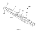
spiral piece 56R may be used.Fig. 12 is a perspective view showing a rotating unit 54M1 according to another embodiment. In the rotating unit 54M1, arch-like transport pieces 560 forming the spiral of thesecond transport member 56 are located up to the position where thespiral piece 56R exists inFig. 10 . That is, in the rotating unit 54M1, the spiral of thesecond transport member 56 is formed throughout thefirst portion 54A. The toner transport operation by thefirst transport member 55 and thesecond transport member 56 is the same as that of the rotatingunit 54 ofFig. 10 . - As described above, in the rotating unit 54 (54M1) of this embodiment, the radially inner portion (the first transport member 55) and the radially outer portion (the second transport member 56) transport toner in different directions. First, the toner transport operation by the rotating unit 54M1 shown in
Fig. 12 will be described with reference toFig. 13 andFig. 14 .Fig. 13 is a schematic sectional side view of atoner container 50A, for illustrating the toner transport operation by the rotating unit 54M1.Fig. 14 is a schematic sectional side view of thetoner container 50A with the rotating unit 54M1 rotated 90 degrees from the state ofFig. 13 . - The
second transport member 56 is rotationally driven and thereby applies a pressing force in the second transport direction to toner. Toner that moves toward thecylindrical portion 52 due to thesecond transport member 56 moves exclusively in the vicinity of the outer circumference of the rotating unit as shown by arrows C1 in the figures. Thesecond transport member 56 does not exist in thecylindrical portion 52. However, the dispersingmembers 57 existing in about the same orbit as thesecond transport member 56 in the radial direction of therotating shaft 541 cause the toner near the inner circumferential wall of thecylindrical portion 52 to flow and thus the force that propels toner in the second transport direction is maintained. Thus, also in thecylindrical portion 52, in a part near the inner wall thereof, toner moves toward thesecond end portion 524 as shown byarrows C 1. - Toner transported in the second transport direction finally reaches the
second end portion 524 of thecylindrical portion 52. Being pressed by thefilm 546, part of toner that has reached falls through thedischarge port 521 into thehousing 60. - Toner that has not been discharged through the
discharge port 521 is reversely transported by the driving of thefirst transport member 55, as shown by arrows C2 in the figures, exclusively in the part of thecylindrical portion 52 near the central axis, in the first transport direction. The reversely transported toner passes across the border between thecylindrical portion 52 and themain body 51, and while being dispersed in the radial direction (the direction toward the central axis) by the dispersingmembers 57, the toner is returned to themain body 51. - As described above, the toner container 50 (50A) of this embodiment has such a circulation movement that toner sent out to the
cylindrical portion 52 by thesecond transport member 56 is returned to themain body 51 by thefirst transport member 55. For this reason, even in atoner container 50 in which adischarge port 521 is located at the distal end of acylindrical portion 52, toner can be prevented from clumping in the vicinity of thedischarge port 521. - The
cylindrical portion 52 has a tubular internal space that has an internal diameter slightly greater than the external diameter of the spiral of thesecond transport member 56. In the case where in atoner container 50 having such acylindrical portion 52, the rotatingunit 54 only transports toner in the second transport direction, and if the amount of discharged toner is less than the amount of moved toner, toner is trapped and packed in thecylindrical portion 52 and finally clumps. Clumps of toner block thedischarge port 521, thereby preventing toner from being discharged. - In the
toner container 50 of this embodiment, thefirst transport member 55 is positioned in thecylindrical portion 52 and reversely transports toner in the first transport direction, and thus toner is not packed. In thecylindrical portion 52, toner cannot move radially outward, and thus toner tries to move toward the axis of thecylindrical portion 52. In the axis part, thefirst transport member 55 is positioned and transports toner in the first transport direction. Thus, before toner clumps, toner can be efficiently returned from thecylindrical portion 52 to themain body 51. - The above-described circulation movement is promoted in the case where a rotating
unit 54 having thespiral piece 56R shown inFig. 10 is used.Fig. 15 is a schematic sectional side view of atoner container 50, for illustrating the toner transport operation by the rotatingunit 54 ofFig. 10 . The toner transport operation by thefirst transport member 55 and thesecond transport member 56 is the same as the operation described with reference toFig. 13 andFig. 14 . - In the
cylindrical portion 52, the outward movement of toner in the radial direction of therotating shaft 541 is limited. Also in the vicinity of the border between thecylindrical portion 52 and themain body 51, the movement of toner is limited compared to the toner in themain body 51. In the vicinity of the border, thespiral piece 56R can generate a pressing force in the direction of arrow C3 that sends out toner from thecylindrical portion 52 to themain body 51. Toner pushed back in the direction of arrow C3 is dispersed by the dispersingmembers 57, as shown by arrow C4, in the radial direction of the rotatingunit 54. Thus, in the vicinity of the border, the collision between toner transported forward in the second transport direction by thesecond transport member 56 and toner transported reversely in the first transport direction by thefirst transport member 55 is reduced, and toner can be smoothly returned from thecylindrical portion 52 to themain body 51. - An arrangement of the
spiral piece 56R will be described. In order to cause thespiral piece 56R to optimally generate a transporting force that returns toner from thecylindrical portion 52 to themain body 51, it is important that thespiral piece 56R is inclined at an appropriate angle. As shown inFig. 16 , in the side view of the rotatingunit 54, when the acute angle between the spiral of the second transport member 56 (thespiral part 56F adjacent to thespiral piece 56R and closest to the cylindrical portion 52) and the dispersingmembers 57 extending parallel to therotating shaft 541 is α, and the angle between thespiral piece 56R and the dispersingmembers 57 is β, it is preferable that the following expression be satisfied:
- In the above expression (1), when the relationship α > β is satisfied, the amount of toner that the
spiral piece 56R can transport per revolution of the rotatingunit 54 is greater than the amount of toner that the spiral (spiral part 56F) of thesecond transport member 56 can transport per revolution of the rotatingunit 54. This is due to the fact that the pitch of thespiral piece 56R in the axial direction of therotating shaft 541 is longer than that of thespiral part 56F. Thus, in the vicinity of the border, the transporting force in the first transport direction (the force that returns developer) is greater than the transporting force in the second transport direction. In the above expression (1), when the relationship β > 0.7α is satisfied, the angle of thespiral piece 56R is not too small, and a shortage of transporting force in the first transport direction is avoided. - The inclination angle α of the spiral of the
second transport member 56 needs to be neither too steep nor too gradual in order to achieve appropriate transportation in the second transport direction. The range of the preferable inclination angle α is at least 45 degrees but no more than 80 degrees, and is more preferably at least 55 degrees but no more than 70 degrees. The inclination angle β of thespiral piece 56R is set in relation to such a preferable inclination angle α so as to satisfy the above expression (1). - The results of an experiment with respect to the appropriate inclination angle P of the
spiral piece 56R is set forth below. Atoner container 50 shown inFig. 9 was made of the following components: -
cylindrical portion 52; internal diameter = 17 mm, length = 45 mm -
main body 51; width of part communicating withcylindrical portion 52 = 17 mm, length = 100 mm -
first transport member 55; external diameter = 9 mm, pitch = 10 mm, external diameter ofrotating shaft 541 = 5 mm -
second transport member 56; maximum external diameter = 21 mm, minimum external diameter = 16 mm, internal diameter = 14 mm, pitch = 20 mm, external diameter decreases towardcylindrical portion 52. Inclination angle α of spiral was set to 62.2 degrees. - dispersing
members 57; width in circumferential direction = 1 mm -
spiral piece 56R; external diameter = 18 mm, internal diameter = 14 mm. Seven different inclination angles β: 68.5 degrees, 62.2 degrees, 56.7 degrees, 51.7 degrees, 47.4 degrees, 43.5 degrees, and 40.2 degrees were prepared. (The inclination angle β is determined by the length of the pitch.) - The
cylindrical portion 52 of the above-describedtoner container 50 was filled with 4.3 grams of yellow toner, and themain body 51 was filled with 100 grams of black toner. The rotatingunit 54 was rotated for 15 minutes with thedischarge port 521 closed. After that, part of toner was obtained from the upper layer of toner contained in themain body 51, and the density (L-value) thereof was measured with a Macbeth reflection densitometer RD-19I (manufactured by Macbeth). The same measurement was carried out on seventoner containers 50 that differ in the inclination angle β of thespiral piece 56R as described above. The results are shown in Table 1 andFig. 17 .Table 1 Pitch of spiral piece 56R15 20 25 30 35 40 45 Angle (β) 68.5 62.2 56.7 51.7 47.4 43.5 40.2 Angle ratio (β/α) 1.1 1 0.91 0.831 0.761 0.699 0.646 L- value 13 13.01 13.73 13.94 13.5 13.01 13.01 - As is clear from Table 1 and
Fig. 17 , intoner containers 50 in which the inclination angle β of thespiral piece 56R is 56.7 degrees, 51.7 degrees, and 47.4 degrees, that is, β/α is within the range of 0.7 to 1.0, the L-values were high. This demonstrates that the yellow toner filling thecylindrical portion 52 was returned to themain body 51 and mixed with black toner, and as a result, the lightness increased. In the other toner containers, the L-values were low, so it can be seen that the amount of yellow toner mixed with black toner in themain body 51 was small. From the above experimental results, it was confirmed that the inclination angle β is preferably set within the range of the above expression (1). - According to the embodiment described above, in a
toner container 50 having a container shape including amain body 51 and acylindrical portion 52 extending from themain body 51 and having adischarge port 521, toner can be prevented from clumping in thecylindrical portion 52. Thus, atoner container 50 that can supply toner stored in amain body 51 to the developingunit 33 such that a little toner remains in the main body, can be provided. - Although a
toner container 50 and animage forming apparatus 1 according to the previous embodiment of the present invention has been described, the present invention is not limited thereto. For example, the following other embodiments can be made. - (1) In the previous embodiment, a
toner container 50 is shown as a specific example of a developer case. Examples of developer cases include a developing unit that combines a toner reservoir, a developing roller, and others, and an intermediate hopper interposed between a toner container and a developing unit. - (2) In the previous embodiment, an example in which the
first transport member 55 is formed over the entire length of therotating shaft 541 in the axial direction is shown. Thefirst transport member 55 is formed at least in thesecond portion 54B of therotating shaft 541.Fig. 18 is a schematic sectional side view of atoner container 50B having a rotating unit 54M2 according to another embodiment. As shown, thefirst transport member 550 is formed on the circumferential surface of therotating shaft 541, only in thesecond portion 54B corresponding to thecylindrical portion 52 of thetoner container 50B. As in the above-described embodiment, thesecond transport member 56 is positioned only in thefirst portion 54A corresponding to themain body 51. Even in the rotating unit 54M2 having such a configuration, thefirst transport member 550 returns toner from thecylindrical portion 52 to themain body 51, and thus toner can be prevented from clumping in thecylindrical portion 52. - (3) In the previous embodiment, an example in which a
rectangular film 546 is attached to the end of therotating shaft 541 of the rotatingunit 54 is shown. Instead of this, a rotating unit 54M3 to which atrapezoidal film 546A is attached, such as that shown inFig. 19 , may be used. Thefilm 546A has abase end portion 546B attached to thetubular holding piece 544 and afree end portion 546T on the side opposite to thebase end portion 546B. The length of thefree end portion 546T in the axial direction of therotating shaft 541 is greater than that of thebase end portion 546B. Part of thefree end portion 546T (extension portion 546E) is located over thesecond end portion 543 of therotating shaft 541. - Actually, it is difficult to form the spirals of the
first transport member 55 and thesecond transport member 56 such that they extend to the immediate vicinity of thesecond end portion 543 of therotating shaft 541. Thus, in the vicinity of thesecond end portion 543, there is virtually no member that applies a pressing force to toner, and toner tends to be less fluid. In this case, instead of therectangular film 546 shown inFig. 9 andFig. 10 , by using afilm 546A having anextension portion 546E, toner can be made more fluid in the vicinity of thesecond end portion 543. That is, with the rotation of therotating shaft 541, theextension portion 546E agitates toner in the vicinity of thesecond end portion 543 and promotes the flow of toner. This facilitates the discharge of toner through thedischarge port 521 and the transportation of toner in the first transport direction by thefirst transport member 55. - (4) Generally, a toner container is equipped with a toner sensor that detects the remaining amount of toner in the container. Other embodiments in the relationship between the arrangement of the toner sensor and the structure of the rotating unit will be exemplified.
Fig. 20A andFig. 21 are schematic sectional side views oftoner containers toner container 50D is provided with the rotating unit 54M1 exemplified inFig. 12 . That is, a rotating unit 54M1 in which the spiral of thesecond transport member 56 is formed over substantially the entire length of themain body 51 in the axial direction, is provided. On the other hand, thetoner container 50E shown inFig. 21 has a rotating unit 54M4 in which the spiral length of thesecond transport member 56 is relatively short. Specifically, thesecond transport member 56 is not formed in part of themain body 51 close to thecylindrical portion 52. -
Fig. 20B is a sectional view of thetoner container 50D in a direction perpendicular to the axial direction of therotating shaft 541. As shown inFig. 20B , atoner sensor 7 that detects the remaining amount of toner is attached to the outer surface of thesecond side wall 513 of themain body 51 in the vicinity of the border between themain body 51 and thecylindrical portion 52. Thetoner sensor 7 is a flat plate-like magnetic sensor and outputs a voltage signal corresponding to the remaining amount of toner in the toner container. That is, when toner exists at a position facing the toner sensor 7 (the position shown by dotted line inFig. 20A andFig. 21 ), thetoner sensor 7 outputs a high voltage; and when toner does not exist at the position, thetoner sensor 7 outputs a low voltage. - In the
toner container 50D, when the remaining amount of toner in the container is small, the surface of toner is highest at thecylindrical portion 52 side end of themain body 51 and slopes downwardly as shown inFig. 20A . On the other hand, in thetoner container 50E, when the amount of toner remaining in the container is small, the surface of toner is flat in the part of themain body 51 close to thecylindrical portion 52 as shown inFig. 21 . This is caused by the fact that in the part close to thecylindrical portion 52, the pressing force exerted on toner by thesecond transport member 56 is relatively weak. In contrast, in thetoner container 50D, the pressing force exerted on toner by thesecond transport member 56 reaches the vicinity of thecylindrical portion 52. Thus, when thetoner container 50D becomes close to empty, toner can be caused to flow in a state where there is a difference in height, in the vicinity of thetoner sensor 7. -
Fig. 22 is a graph showing the sensitivities of thetoner sensors 7 of the above-describedtoner containers first output curve 71 of thetoner sensor 7 of thetoner container 50D is flat until the remaining amount of toner becomes considerably small, and then decreases steeply. On the other hand, thesecond output curve 72 of thetoner sensor 7 of thetoner container 50E starts to decrease while the remaining amount of toner is relatively large. From this graph, it can be seen that thetoner sensor 7 of thetoner container 50D is more sensitive than thetoner sensor 7 of thetoner container 50E in the stage where the remaining amount of toner is small. As is clear from the comparison between theempty levels toner sensor 7 of thetoner container 50D outputs a signal corresponding to "empty" is smaller than the remaining amount of toner when thetoner sensor 7 of thetoner container 50E outputs a signal corresponding to "empty." - From the above, it is preferable that a rotating unit 54M1 in which the spiral of the
second transport member 56 is formed over substantially the entire length of themain body 51 in the axial direction be used as a rotating unit and that thetoner sensor 7 be attached to a position where thecylindrical portion 52 side end of thesecond transport member 56 exists. When the toner container becomes close to empty, toner can be caused to flow in a state where there is a difference in height, in the vicinity of thetoner sensor 7, and the sensitivity (resolution) of thetoner sensor 7 can be improved. - (5) In the previous embodiment, an example in which the
toner container 50 is connected horizontally to the developingunit 33 is shown. Instead of this, as shown inFig. 23 , atoner container 50F may be connected to the developingunit 33 at an angle. Specifically, thetoner container 50F may be connected to the developingunit 33 with thecylindrical portion 52 having thedischarge port 521 lowered and themain body 51 side inclined upwardly. This configuration is preferable because toner can also be guided to thedischarge port 521 by gravity. - In this case, it is preferable that the inclination angle of the
bottom wall 511 of thetoner container 50F with respect to the horizontal direction H be less than the angle of repose of toner contained in thetoner container 50F. For example, if the angle of repose of toner is 38 degrees, the inclination angle is preferably less than 35 degrees. This can prevent the transportability of toner in the first transport direction from worsening. When the inclination angle exceeds the angle of repose, the reverse transportation of toner by thefirst transport member 55 becomes difficult. - Next, with reference to
Fig. 24 to Fig. 26 , the structure of atoner container 500 in another embodiment will be described.Fig. 24 is a sectional side view of thetoner container 500,Fig. 25 is a perspective view of arotating unit 540 located in thetoner container 500, andFig. 26 is a side view of therotating unit 540 with accompanying partial sectional views. This embodiment is the same as the previous embodiment except for the configuration of the rotating unit of the toner container. So, the same reference numerals will be used to designate the same components as those in the previous embodiment, and the description thereof will be omitted. - As shown in
Fig. 24 andFig. 25 , therotating unit 540 is positioned so as to straddle themain body 51 and thecylindrical portion 52 and includes afirst portion 54A located in themain body 51 and asecond portion 54B located in thecylindrical portion 52. Thefirst transport member 55 and thesecond transport member 56 are formed over substantially the entire length of therotating shaft 541 in the axial direction. That is, thefirst transport member 55 and thesecond transport member 56 exist in both thefirst portion 54A and thesecond portion 54B. The dispersingmembers 57 are also positioned so as to straddle thefirst portion 54A and thesecond portion 54B. - The external diameter of the spiral of the
first transport member 55 is uniform throughout therotating shaft 541 in the axial direction. On the other hand, the external diameter of the spiral of thesecond transport member 56 decreases from thefirst end portion 542 of therotating shaft 541 toward thesecond end portion 543 thereof as shown inFig. 26 . Such a reduction in external diameter of the spiral is achieved by changing the thickness of the arch-like transport pieces of thesecond transport member 56 in the radial direction. On the other hand, the internal diameter of the spiral of thesecond transport member 56 is uniform over the entire length of therotating shaft 541 in the axial direction. - In a part P1 near the
first end portion 542 of therotating shaft 541, the thickness of the arch-like transport piece of thesecond transport member 56 in the radial direction (the extending height from the dispersing members 57) is T1, which is the thickest, as shown in the circle. In a part P2 near the middle of therotating shaft 541 in the axial direction, the thickness of the arch-like transport piece in the radial direction is T2, which is thinner than T1. In a part P3 near thesecond end portion 543, the thickness of the arch-like transport piece in the radial direction is T3, which is thinner than T2. That is, T1 > T2 > T3, and thus the envelope line L of arch-like transport pieces is inclined at an angle θ to the dispersingmembers 57 extending in the horizontal direction H. In other words, the spiral of thesecond transport member 56 has a tapered shape that tapers at an angle θ. Thecylindrical portion 52 also has a tapered shape that tapers at an angle θ. - When a rotational drive force that rotates the
rotating shaft 541 in a predetermined rotation direction is applied to thecontainer gear 54G, thefirst transport member 55 and thesecond transport member 56 generate toner-transporting forces corresponding to their respective spiral directions. Thesecond transport member 56 transports toner in a direction from themain body 51 toward the cylindrical portion 52 (discharge port 521). That is, thesecond transport member 56 transports toner from thefirst end portion 542 of therotating shaft 541 to thesecond end portion 543 thereof. On the other hand, thefirst transport member 55 transports toner in a direction from thecylindrical portion 52 to themain body 51. That is, thefirst transport member 55 transports toner from thesecond end portion 543 of therotating shaft 541 to thefirst end portion 542 thereof. - The dispersing
members 57 serve to disperse toner transported by thefirst transport member 55 and thesecond transport member 56, in the radial direction of therotating shaft 541. That is, the dispersingmembers 57 disperse toner existing around the toner propelled by the arch-like transport pieces of thefirst transport member 55 and thesecond transport member 56, in the radial direction. Thus, the movement of toner in the first transport direction or the second transport direction is promoted. - As described above, in the
rotating unit 540 of this embodiment, the radially inner portion (the first transport member 55) and the radially outer portion (the second transport member 56) transport toner in different directions. The toner transport operation by therotating unit 540 will be described with reference toFig. 27 andFig. 28 .Fig. 27 is a schematic sectional side view of a toner container, for illustrating the toner transport operation by the rotating unit.Fig. 28 is a schematic horizontal sectional view of the toner container and the developing unit. - The
second transport member 56 is rotationally driven and thereby applies a pressing force in the second transport direction to toner. Toner caused to move toward thecylindrical portion 52 by thesecond transport member 56 moves exclusively in the vicinity of the outer circumference of the rotating unit as shown by arrows C1. The same is true in thecylindrical portion 52. In the vicinity of the inner circumferential wall of thecylindrical portion 52, toner moves toward thesecond end portion 524. At the same time, the dispersingmembers 57 disperse toner in the vicinity of thesecond transport member 56 in the radial direction, and thus toner moves smoothly in the second transport direction. - Toner transported in the second transport direction finally reaches the
second end portion 524 of thecylindrical portion 52. Being pressed by thefilm 546, part of toner falls through thedischarge port 521 into thehousing 60. The toner is circulated in thehousing 60 by the first andsecond screws - Toner that has not been discharged through the
discharge port 521 is reversely transported by the driving of thefirst transport member 55, as shown by arrows C2 in the figures, exclusively in the part of thecylindrical portion 52 near the central axis, in the first transport direction. The reversely transported toner passes across the border between thecylindrical portion 52 and themain body 51, and while being dispersed in the radial direction (the direction toward the central axis) by the dispersingmembers 57, the toner is returned to themain body 51. - As described above, the
toner container 500 of this embodiment has such a circulation movement that toner moved to thecylindrical portion 52 by thesecond transport member 56 is returned to themain body 51 by thefirst transport member 55. For this reason, even in atoner container 500 in which adischarge port 521 is located at the distal end of acylindrical portion 52, toner can be prevented from clumping in the vicinity of thedischarge port 521. - The
cylindrical portion 52 has an internal space that has a circular cross-sectional shape corresponding to the rotation locus of thesecond transport member 56, which is the most radially extending part of therotating unit 540, that is, a tubular internal space that has an internal diameter slightly greater than the external diameter of the spiral of thesecond transport member 56. In the case where in atoner container 500 having such acylindrical portion 52, therotating unit 540 only transports toner in the second transport direction, and if the amount of discharged toner is less than the amount of sent toner, toner is trapped and packed in thecylindrical portion 52 and finally clumps. Clumps of toner block thedischarge port 521, thereby preventing toner from being discharged. In thetoner container 500 of this embodiment, thefirst transport member 55 has a transport function to reversely transport toner in the first transport direction in thecylindrical portion 52, and thus toner is not packed. In thecylindrical portion 52, toner cannot move radially outward, and thus toner tries to move toward the axis of thecylindrical portion 52. In the axis part, thefirst transport member 55 is disposed and transports toner in the first transport direction. Thus, before toner clumps, toner can be efficiently returned from thecylindrical portion 52 to themain body 51. - In particular, in the
rotating unit 540 of this embodiment, the external diameter of the spiral of thesecond transport member 56 decreases toward the second transport direction, and the internal diameter of thecylindrical portion 52 also decreases toward the distal end (second end portion 524). For this reason, toner is smoothly transported along these tapered shapes toward the discharge opening 521 (toward the distal end) of thecylindrical portion 52. On the other hand, the internal diameter of the spiral of thesecond transport member 56 is substantially uniform over the entire length of therotating shaft 541 in the axial direction. For this reason, the transportation of toner in the first transport direction by thefirst transport member 55 located inside is not hindered. Thus, toner can be stably returned from thecylindrical portion 52 to themain body 51 by thefirst transport member 55. - According to this embodiment, in a
toner container 500 having a container shape including amain body 51 and acylindrical portion 52 extending from themain body 51 and having adischarge port 521, toner can be prevented from clumping in thecylindrical portion 52. Thus, atoner container 500 that can supply toner stored in amain body 51 to the developingunit 33 such that little toner remains in the main body, can be provided. - Although a
toner container 500 according to another embodiment of the present invention has been described, the present invention is not limited to this. For example, the following other embodiments can be made. - (1) In the above-described embodiment, a
toner container 500 is shown as a specific example of a developer case. Examples of developer cases include a developing unit that combines a toner reservoir, a developing roller, and others, and an intermediate hopper interposed between a toner container and a developing unit. - (2) In the above-described embodiment, an example in which a
rectangular film 546 is attached to the end of therotating shaft 541 of therotating unit 540 is shown. Instead of this, atrapezoidal film 546A, such as that shown inFig. 19 , may be attached. - (3) The above-described example of the
rotating unit 540 will be described with reference toFig. 29. Fig. 29 is a partial sectional view of therotating unit 540. A preferable embodiment concerning the relationship between the thickness of the dispersingmembers 57 and the distance between the outermost circumference of the spiral of thefirst transport member 55 and the radially inner surface of the pair of dispersingmembers 57 will be shown. The thickness of the dispersingmembers 57 in the radial direction of therotating shaft 541 is denoted by D1. The distance between the outermostcircumferential part 55A of the spiral of thefirst transport member 55 and the radiallyinner surface 57A of the pair of dispersingmembers 57 is denoted by D2. - In this case, it is preferable that the distance D2 be greater than the thickness D1. Since the distance D2 is greater than the thickness D1, a sufficient space exists between the outermost
circumferential part 55A of the spiral of thefirst transport member 55 and the radiallyinner surface 57A of the pair of dispersingmembers 57. Thus, the region where toner is transported by thefirst transport member 55 is secured in the inside of the spiral of thesecond transport member 56. Thus, toner can be reliably transported in the first transport direction by thefirst transport member 55. - The invention has been described with reference to particular embodiments. Yet, it shall be clear that features mentioned in the description of one embodiment may well be implemented in the other embodiment.
- Disclosed is a developer case comprising:
- a main body having a bottom wall and containing developer;
- a cylindrical portion connected to the bottom wall, extending from the main body, and having a discharge port; and
- a rotating unit positioned so as to extend across the main body and the cylindrical portion and transporting the developer in the main body,
- wherein the rotating unit includes
- a rotating shaft that extends in a direction in which the bottom wall extends and has a first portion located in the main body and a second portion located in the cylindrical portion,
- a first transport member that is located on the circumferential surface of the second portion of the rotating shaft, rotates integrally with the rotating shaft, and transports the developer in a first transport direction from the cylindrical portion to the main body,
- a second transport member that is located over the circumferential surface of the first portion of the rotating shaft and on the radially outer side of the first transport member, rotates integrally with the rotating shaft, and transports the developer at least in a second transport direction from the main body to the cylindrical portion, and
- dispersing members that extend parallel to the rotating shaft and across the first portion and the second portion and move the developer in the radial direction.
- In the above developer case the first transport member may also be positioned on the circumferential surface of the first portion of the rotating shaft. Preferably the first transport member spirally extends from the circumferential surface of the rotating shaft, and the second transport member is spiral and has a hollow portion into which the rotating shaft having the first transport member can be inserted. More preferably the second transport member has a spiral piece that transports the developer in the first transport direction, toward the cylindrical portion-side end of the first portion. Even more preferably the following expression is satisfied:

where α is the acute angle between the spiral of the second transport member and the dispersing members, and β is the acute angle between the spiral piece and the dispersing members. - In the above developer case the dispersing members can be attached to the second transport member and have a thickness D1 in the radial direction of the rotating shaft, and a distance D2 between the outermost circumference of the spiral of the first transport member and the radially inner surface of the dispersing members can be greater than the thickness D1.
- In the above developer case the discharge port may be an opening located in the lower surface of the cylindrical portion, and a flexible pressing member may extend in a direction perpendicular to the axial direction of the rotating shaft is attached to part of the rotating shaft corresponding to the opening. Preferably the rotating shaft has a holding piece integrally attached to the cylindrical portion-side end thereof, the flexible pressing member is a film, and the film has a base end portion attached to the holding piece and a free end portion on the side opposite to the base end portion, and the length of the free end portion in the axial direction of the rotating shaft is greater than that of the base end portion, and part of the free end portion is located over the rotating shaft.
- The developer case may comprise a sensor that detects the developer, and the sensor is attached to part of the side surface of the main body where the cylindrical portion-side end of the second transport member is located.
- In the above developer case the cylindrical portion may have an inner wall surface that is circular in cross-section, the bottom wall of the main body may have a semicircular inner wall surface corresponding to the rotation locus of the most radially extending part of the second transport member, and the semicircular inner wall surface is connected to the circular inner wall surface of the cylindrical portion, the main body may include a first side wall that extends upwardly from one end of the bottom wall, a second side wall that extends upwardly from the other end of the bottom wall and faces the first side wall, a third side wall that connects one end edge of the first side wall and one end edge of the second side wall, and a fourth side wall that faces the third side wall and connects the other end edge of the first side wall and the other end edge of the second side wall, the cylindrical portion may extend from the third side wall, and the rotating shaft may have a first end portion and a second end portion on the side opposite to the first end portion, the first end portion is rotatably supported by the fourth side wall, and the second end portion is rotatably supported by the extending distal end surface of the cylindrical portion.
- Further disclosed is an image forming apparatus comprising:
- an image bearing member that bears a developer image on the circumferential surface thereof;
- a developing unit that supplies developer to the image bearing member; and
- a developer case that is detachably connected to the developing unit and supplies the developer to the developing unit,
- wherein the developer case includes
- a main body having a bottom wall and containing developer,
- a cylindrical portion connecting to the bottom wall, extending from the main body, and having a discharge port, and
- a rotating unit located so as to extend across the main body and the cylindrical portion and transports the developer in the main body, and
- the rotating unit includes
- a rotating shaft that extends in a direction in which the bottom wall extends and that has a first portion located in the main body and a second portion located in the cylindrical portion,
- a first transport member that is located on the circumferential surface of the second portion of the rotating shaft, rotates integrally with the rotating shaft, and transports the developer in a first transport direction from the cylindrical portion to the main body,
- a second transport member that is located over the circumferential surface of the first portion of the rotating shaft and on the radially outer side of the first transport member, rotates integrally with the rotating shaft, and transports the developer in a second transport direction from the main body to the cylindrical portion, and
- dispersing members that extend parallel to the rotating shaft and across the first portion and the second portion and move the developer in the radial direction.
- In the above image forming apparatus the developing unit may have a developing roller that supplies developer to the circumferential surface of the image bearing member, and a housing having a shape that is elongate in a first direction along the axial direction of the developing roller, and the developer case may be connected to the developing unit such that the rotating shaft extends in a second direction perpendicular to the first direction.
- In the above image forming apparatus the developer case may be connected to the developing unit with the discharge port being lower and the main body side inclined upwardly, and the inclination angle of the developer case may be less than the angle of repose of the developer contained in the developer case.
- Also disclosed is a developer case comprising:
- a main body having a bottom wall and containing developer;
- a cylindrical portion connecting to the bottom wall, protruded from the main body, and having a discharge port; and
- a rotating unit provided so as to extend across the main body and the cylindrical portion and transporting the developer in the main body,
- wherein the rotating unit includes
- a rotating shaft that extends in a direction in which the bottom wall extends,
- a first transport member that is located on the circumferential surface of the rotating shaft, rotates integrally with the rotating shaft, and transports the developer in a first transport direction from the cylindrical portion to the main body, and
- a second transport member that is located over the circumferential surface of the rotating shaft and on the radially outer side of the first transport member, rotates integrally with the rotating shaft, and transports the developer at least in a second transport direction from the main body to the cylindrical portion, and
- the cylindrical portion has an inner wall surface that is circular in cross-section and corresponds to the rotation locus of the most radially extending part of the second transport member.
- Also disclosed is an image forming apparatus comprising:
- an image bearing member that bears a developer image on the circumferential surface thereof;
- a developing unit that supplies developer to the image bearing member; and
- a developer case that is detachably connected to the developing unit and supplies the developer to the developing unit,
- wherein the developer case includes
- a main body having a bottom wall and containing developer,
- a cylindrical portion connecting to the bottom wall, extending from the main body, and having a discharge port, and
- a rotating unit located so as to extend across the main body and the cylindrical portion and transports the developer in the main body,
- the rotating unit includes
- a rotating shaft that extends in a direction in which the bottom wall extends,
- a first transport member that is located on the circumferential surface of the rotating shaft, rotates integrally with the rotating shaft, and transports the developer in a first transport direction from the cylindrical portion to the main body,
- a second transport member that is located over the circumferential surface of the rotating shaft and on the radially outer side of the first transport member, rotates integrally with the rotating shaft, and transports the developer in a second transport direction from the main body to the cylindrical portion, and
- the cylindrical portion has an inner wall surface that is circular in cross-section and corresponds to the rotation locus of the most radially protruding part of the second transport member.
Claims (14)
- A developer case (50) comprising:a main body (51) having a bottom wall (511) and containing developer;a cylindrical portion (52) connected to the bottom wall (511), extending from the main body (51), and having a discharge port (521); anda rotating unit (54) positioned so as to extend across the main body (51) and the cylindrical portion (52) and transporting the developer in the main body (51),wherein the rotating unit (54) includesa rotating shaft (541) that extends in a direction in which the bottom wall (511) extends and has a first portion (54A) located in the main body (51) and a second portion (54B) located in the cylindrical portion (52),a first transport member (55) that is located on the circumferential surface of the second portion (54B) of the rotating shaft (541), rotates integrally with the rotating shaft (541), and transports the developer in a first transport direction from the cylindrical portion (52) to the main body (51),a second transport member (56) that is located over the circumferential surface of the first portion (54A) of the rotating shaft (541) and on the radially outer side of the first transport member (55), rotates integrally with the rotating shaft (541), and transports the developer at least in a second transport direction from the main body (51) to the cylindrical portion (52), anddispersing members (57) that extend parallel to the rotating shaft (541) and across the first portion (54A) and the second portion (54B) and move the developer in the radial direction.wherein the first portion (54A) and the second portion (54B) are located along a direction of the rotating shaft (541).
- The developer case (50) according to Claim 1, wherein the rotating shaft (541) extends across the first portion (54A) and the second portion (54B).
- The developer case (50) according to Claim 1 or 2, wherein the first transport member (55) is also positioned on the circumferential surface of the first portion (54A) of the rotating shaft (541).
- The developer case (50) according to Claim 3, wherein
the first transport member (55) spirally extends from the circumferential surface of the rotating shaft (541), and
the second transport member (56) is spiral and has a hollow portion into which the rotating shaft (541) having the first transport member (55) can be inserted. - The developer case (50) according to Claim 4, wherein the second transport member (56) has a spiral piece (56R) that transports the developer in the first transport direction, toward the cylindrical portion-side end of the first portion (54A).
- The developer case (50) according to Claim 5, wherein the following expression is satisfied:

where α is the acute angle between the spiral of the second transport member and the dispersing members (57), and β is the acute angle between the spiral piece (56R) and the dispersing members (57). - The developer case (50) according to Claim 4, 5 or 6, wherein
the dispersing members (57) are attached to the second transport member (56) and have a thickness D1 in the radial direction of the rotating shaft (541), and
a distance D2 between the outermost circumference of the spiral of the first transport member (55) and the radially inner surface of the dispersing members (57) is greater than the thickness D1. - The developer case (50) according to any of the preceding Claims, wherein
the discharge port (521) is an opening located in the lower surface of the cylindrical portion (52), and
a flexible pressing member (546) extending in a direction perpendicular to the axial direction of the rotating shaft (541) is attached to part of the rotating shaft (541) corresponding to the opening. - The developer case (50) according to Claim 8, wherein
the rotating shaft (541) has a holding piece (544) integrally attached to the cylindrical portion-side end thereof,
the flexible pressing member (546) is a film (546A), and the film (546A) has a base end portion (546B) attached to the holding piece (544) and a free end portion (546T) on the side opposite to the base end portion (546B), and
the length of the free end portion (546T) in the axial direction of the rotating shaft (541) is greater than that of the base end portion (546B), and part of the free end portion (546T) is located over the rotating shaft (541). - The developer case (50) according to any of the preceding Claims comprising a sensor (7) that detects the developer, and the sensor (7) is attached to part of the side surface of the main body (51) where the cylindrical portion-side end of the second transport member (56) is located.
- The developer case (50) according to any of the preceding Claims, wherein
the cylindrical portion (52) has an inner wall surface that is circular in cross-section,
the bottom wall (511) of the main body (51) has a semicircular inner wall surface corresponding to the rotation locus of the most radially extending part of the second transport member (56), and the semicircular inner wall surface is connected to the circular inner wall surface of the cylindrical portion (52),
the main body (51) includes a first side wall (512) that extends upwardly from one end of the bottom wall (511), a second side wall (513) that extends upwardly from the other end of the bottom wall (511) and faces the first side wall (512), a third side wall (514) that connects one end edge of the first side wall (512) and one end edge of the second side wall (513), and a fourth side wall (53) that faces the third side wall (514) and connects the other end edge of the first side wall (512) and the other end edge of the second side wall (513),
the cylindrical portion (52) extends from the third side wall (514), and
the rotating shaft (541) has a first end portion (542) and a second end portion (543) on the side opposite to the first end portion (542), the first end portion (542) is rotatably supported by the fourth side wall (53), and the second end portion (543) is rotatably supported by the extending distal end surface of the cylindrical portion (52). - An image forming apparatus (1) comprising:an image bearing member (31) that bears a developer image on the circumferential surface thereof;a developing unit (33) that supplies developer to the image bearing member (31); andthe developer case (50) according to any of claims 1-11 being detachably connected to the developing unit (33) and supplying the developer to the developing unit (33).
- The image forming apparatus (1) according to Claim 12, wherein
the developing unit (33) has a developing roller (311) that supplies developer to the circumferential surface of the image bearing member (31), and a housing (60) having a shape that is elongate in a first direction along the axial direction of the developing roller (311), and
the developer case (50) is connected to the developing unit (33) such that the rotating shaft (541) extends in a second direction perpendicular to the first direction. - The image forming apparatus (1) according to Claim 12 or 13, wherein
the developer case (50) is connected to the developing unit (33) with the discharge port (521) being lower and the main body side inclined upwardly, and
the inclination angle of the developer case (50) is less than the angle of repose of the developer contained in the developer case (50).
Applications Claiming Priority (4)
| Application Number | Priority Date | Filing Date | Title |
|---|---|---|---|
| JP2011091260A JP5377564B2 (en) | 2011-04-15 | 2011-04-15 | Developer container and image forming apparatus to which the container is applied |
| JP2011091259 | 2011-04-15 | ||
| JP2011232939A JP5377612B2 (en) | 2011-04-15 | 2011-10-24 | Developer container and image forming apparatus to which the container is applied |
| EP12164241.7A EP2527925B1 (en) | 2011-04-15 | 2012-04-16 | Developer case and image forming apparatus to which developer case is applied |
Related Parent Applications (3)
| Application Number | Title | Priority Date | Filing Date |
|---|---|---|---|
| EP12164241.7 Division | 2012-04-16 | ||
| EP12164241.7A Division EP2527925B1 (en) | 2011-04-15 | 2012-04-16 | Developer case and image forming apparatus to which developer case is applied |
| EP12164241.7A Division-Into EP2527925B1 (en) | 2011-04-15 | 2012-04-16 | Developer case and image forming apparatus to which developer case is applied |
Publications (2)
| Publication Number | Publication Date |
|---|---|
| EP2626750A1 true EP2626750A1 (en) | 2013-08-14 |
| EP2626750B1 EP2626750B1 (en) | 2016-12-07 |
Family
ID=48136080
Family Applications (2)
| Application Number | Title | Priority Date | Filing Date |
|---|---|---|---|
| EP13167141.4A Active EP2626750B1 (en) | 2011-04-15 | 2012-04-16 | Developer case and image forming apparatus to which developer case is applied |
| EP13167132.3A Active EP2626749B1 (en) | 2011-04-15 | 2012-04-16 | Developer case and image forming apparatus to which developer case is applied |
Family Applications After (1)
| Application Number | Title | Priority Date | Filing Date |
|---|---|---|---|
| EP13167132.3A Active EP2626749B1 (en) | 2011-04-15 | 2012-04-16 | Developer case and image forming apparatus to which developer case is applied |
Country Status (2)
| Country | Link |
|---|---|
| US (1) | US8666292B2 (en) |
| EP (2) | EP2626750B1 (en) |
Families Citing this family (6)
| Publication number | Priority date | Publication date | Assignee | Title |
|---|---|---|---|---|
| CN101581910A (en) * | 2009-06-12 | 2009-11-18 | 珠海赛纳科技有限公司 | Processing box |
| JP5086460B2 (en) * | 2011-04-15 | 2012-11-28 | 京セラドキュメントソリューションズ株式会社 | Image forming apparatus |
| JP5526103B2 (en) * | 2011-10-24 | 2014-06-18 | 京セラドキュメントソリューションズ株式会社 | Developer container and image forming apparatus to which the container is applied |
| JP6260129B2 (en) | 2012-10-31 | 2018-01-17 | ブラザー工業株式会社 | Image forming apparatus |
| JP6780253B2 (en) * | 2016-02-05 | 2020-11-04 | 富士ゼロックス株式会社 | Developing equipment and image forming equipment |
| JP7435123B2 (en) * | 2020-03-25 | 2024-02-21 | 富士フイルムビジネスイノベーション株式会社 | Detachable container and container mounting device using the same |
Citations (1)
| Publication number | Priority date | Publication date | Assignee | Title |
|---|---|---|---|---|
| US5307129A (en) * | 1990-10-01 | 1994-04-26 | Fuji Xerox Co., Ltd. | Image processing apparatus |
Family Cites Families (16)
| Publication number | Priority date | Publication date | Assignee | Title |
|---|---|---|---|---|
| US3724725A (en) | 1971-03-30 | 1973-04-03 | Ibm | Electroscopic powder feeding apparatus utilizing rotating helical members |
| JPH02100267A (en) | 1988-10-06 | 1990-04-12 | Tech Res & Dev Inst Of Japan Def Agency | Activation system of thermal battery |
| JPH0546021A (en) | 1991-08-08 | 1993-02-26 | Mita Ind Co Ltd | Developer stirring device provided in developer container |
| JPH0543163A (en) | 1991-08-14 | 1993-02-23 | Toshiba Corp | Straightness correction method for elevator guide rail installation work |
| JPH0553438A (en) | 1991-08-28 | 1993-03-05 | Ricoh Co Ltd | Development device |
| DE60141310D1 (en) | 2000-05-26 | 2010-04-01 | Kyocera Mita Corp | Toner cartridge with toner stirrer |
| JP3673236B2 (en) | 2002-03-28 | 2005-07-20 | 京セラミタ株式会社 | Toner container |
| JP4363035B2 (en) | 2002-12-16 | 2009-11-11 | 富士ゼロックス株式会社 | Image forming apparatus |
| JP4325425B2 (en) * | 2004-02-06 | 2009-09-02 | 富士ゼロックス株式会社 | Developing device and image forming apparatus using the same |
| JP4710760B2 (en) * | 2006-08-29 | 2011-06-29 | 富士ゼロックス株式会社 | Developer transport device and image forming apparatus |
| JP2008268445A (en) | 2007-04-18 | 2008-11-06 | Fuji Xerox Co Ltd | Powder conveying member, powder conveying device using the same, frame, image forming apparatus, and device of manufacturing the powder conveying member |
| JP4492665B2 (en) | 2007-10-03 | 2010-06-30 | 富士ゼロックス株式会社 | Developer stirring and conveying member, developing device, and image forming apparatus provided with the same |
| JP5539678B2 (en) | 2009-07-30 | 2014-07-02 | 京セラドキュメントソリューションズ株式会社 | Developer supply container |
| JP5521476B2 (en) * | 2009-10-07 | 2014-06-11 | 富士ゼロックス株式会社 | Image forming apparatus and toner container |
| JP5521661B2 (en) * | 2010-03-12 | 2014-06-18 | 富士ゼロックス株式会社 | Developer conveying apparatus and image forming apparatus using the same |
| JP5190482B2 (en) | 2010-03-18 | 2013-04-24 | シャープ株式会社 | Toner discharging device, toner cartridge, and image forming apparatus |
-
2012
- 2012-04-16 US US13/447,588 patent/US8666292B2/en active Active
- 2012-04-16 EP EP13167141.4A patent/EP2626750B1/en active Active
- 2012-04-16 EP EP13167132.3A patent/EP2626749B1/en active Active
Patent Citations (1)
| Publication number | Priority date | Publication date | Assignee | Title |
|---|---|---|---|---|
| US5307129A (en) * | 1990-10-01 | 1994-04-26 | Fuji Xerox Co., Ltd. | Image processing apparatus |
Also Published As
| Publication number | Publication date |
|---|---|
| EP2626750B1 (en) | 2016-12-07 |
| EP2626749A1 (en) | 2013-08-14 |
| US20130101317A1 (en) | 2013-04-25 |
| EP2626749B1 (en) | 2016-11-30 |
| US8666292B2 (en) | 2014-03-04 |
Similar Documents
| Publication | Publication Date | Title |
|---|---|---|
| EP2527925B1 (en) | Developer case and image forming apparatus to which developer case is applied | |
| JP5526103B2 (en) | Developer container and image forming apparatus to which the container is applied | |
| KR101457760B1 (en) | Developer container and image forming device equipped with the same | |
| CN102736481B (en) | Image forming apparatus | |
| EP2626749B1 (en) | Developer case and image forming apparatus to which developer case is applied | |
| JP5539678B2 (en) | Developer supply container | |
| JP5540142B2 (en) | Developer container and image forming apparatus to which the container is applied | |
| US9235162B2 (en) | Developer storage container and image forming apparatus with same | |
| JP5619246B2 (en) | Developer container and image forming apparatus to which the container is applied | |
| CN107209470A (en) | Developer container and image forming apparatus having the developer container | |
| JP5663452B2 (en) | Developer container and image forming apparatus to which the container is applied | |
| JP2002174947A (en) | Developer container and image forming apparatus | |
| JP5377564B2 (en) | Developer container and image forming apparatus to which the container is applied | |
| JP5675553B2 (en) | Developer conveying apparatus and image forming apparatus to which the same is applied | |
| CN102033465A (en) | Toner cartridge, image forming apparatus and image forming method |
Legal Events
| Date | Code | Title | Description |
|---|---|---|---|
| PUAI | Public reference made under article 153(3) epc to a published international application that has entered the european phase |
Free format text: ORIGINAL CODE: 0009012 |
|
| AC | Divisional application: reference to earlier application |
Ref document number: 2527925 Country of ref document: EP Kind code of ref document: P |
|
| AK | Designated contracting states |
Kind code of ref document: A1 Designated state(s): AL AT BE BG CH CY CZ DE DK EE ES FI FR GB GR HR HU IE IS IT LI LT LU LV MC MK MT NL NO PL PT RO RS SE SI SK SM TR |
|
| AX | Request for extension of the european patent |
Extension state: BA ME |
|
| 17P | Request for examination filed |
Effective date: 20140210 |
|
| RBV | Designated contracting states (corrected) |
Designated state(s): AL AT BE BG CH CY CZ DE DK EE ES FI FR GB GR HR HU IE IS IT LI LT LU LV MC MK MT NL NO PL PT RO RS SE SI SK SM TR |
|
| GRAP | Despatch of communication of intention to grant a patent |
Free format text: ORIGINAL CODE: EPIDOSNIGR1 |
|
| INTG | Intention to grant announced |
Effective date: 20160628 |
|
| RIN1 | Information on inventor provided before grant (corrected) |
Inventor name: KENICHI, TAMAKI Inventor name: TAKAHISA, NAKAUE Inventor name: YOSHIHIRO, YAMAGISHI Inventor name: TAMOTSU, SHIMIZU Inventor name: IKUO, MAKIE Inventor name: MASAKI, HAYASHI Inventor name: EIJI, NIMURA Inventor name: TAKASHI, MORITA Inventor name: KOJI, KURAMASHI Inventor name: TERUHIKO, NAGASHIMA |
|
| GRAS | Grant fee paid |
Free format text: ORIGINAL CODE: EPIDOSNIGR3 |
|
| GRAA | (expected) grant |
Free format text: ORIGINAL CODE: 0009210 |
|
| STAA | Information on the status of an ep patent application or granted ep patent |
Free format text: STATUS: THE PATENT HAS BEEN GRANTED |
|
| AC | Divisional application: reference to earlier application |
Ref document number: 2527925 Country of ref document: EP Kind code of ref document: P |
|
| AK | Designated contracting states |
Kind code of ref document: B1 Designated state(s): AL AT BE BG CH CY CZ DE DK EE ES FI FR GB GR HR HU IE IS IT LI LT LU LV MC MK MT NL NO PL PT RO RS SE SI SK SM TR |
|
| REG | Reference to a national code |
Ref country code: GB Ref legal event code: FG4D |
|
| REG | Reference to a national code |
Ref country code: CH Ref legal event code: EP Ref country code: AT Ref legal event code: REF Ref document number: 852250 Country of ref document: AT Kind code of ref document: T Effective date: 20161215 |
|
| REG | Reference to a national code |
Ref country code: IE Ref legal event code: FG4D |
|
| REG | Reference to a national code |
Ref country code: DE Ref legal event code: R096 Ref document number: 602012026484 Country of ref document: DE |
|
| PG25 | Lapsed in a contracting state [announced via postgrant information from national office to epo] |
Ref country code: LV Free format text: LAPSE BECAUSE OF FAILURE TO SUBMIT A TRANSLATION OF THE DESCRIPTION OR TO PAY THE FEE WITHIN THE PRESCRIBED TIME-LIMIT Effective date: 20161207 |
|
| REG | Reference to a national code |
Ref country code: FR Ref legal event code: PLFP Year of fee payment: 6 |
|
| REG | Reference to a national code |
Ref country code: LT Ref legal event code: MG4D |
|
| REG | Reference to a national code |
Ref country code: NL Ref legal event code: MP Effective date: 20161207 |
|
| PG25 | Lapsed in a contracting state [announced via postgrant information from national office to epo] |
Ref country code: LT Free format text: LAPSE BECAUSE OF FAILURE TO SUBMIT A TRANSLATION OF THE DESCRIPTION OR TO PAY THE FEE WITHIN THE PRESCRIBED TIME-LIMIT Effective date: 20161207 Ref country code: GR Free format text: LAPSE BECAUSE OF FAILURE TO SUBMIT A TRANSLATION OF THE DESCRIPTION OR TO PAY THE FEE WITHIN THE PRESCRIBED TIME-LIMIT Effective date: 20170308 Ref country code: SE Free format text: LAPSE BECAUSE OF FAILURE TO SUBMIT A TRANSLATION OF THE DESCRIPTION OR TO PAY THE FEE WITHIN THE PRESCRIBED TIME-LIMIT Effective date: 20161207 Ref country code: NO Free format text: LAPSE BECAUSE OF FAILURE TO SUBMIT A TRANSLATION OF THE DESCRIPTION OR TO PAY THE FEE WITHIN THE PRESCRIBED TIME-LIMIT Effective date: 20170307 |
|
| REG | Reference to a national code |
Ref country code: AT Ref legal event code: MK05 Ref document number: 852250 Country of ref document: AT Kind code of ref document: T Effective date: 20161207 |
|
| PG25 | Lapsed in a contracting state [announced via postgrant information from national office to epo] |
Ref country code: ES Free format text: LAPSE BECAUSE OF FAILURE TO SUBMIT A TRANSLATION OF THE DESCRIPTION OR TO PAY THE FEE WITHIN THE PRESCRIBED TIME-LIMIT Effective date: 20161207 Ref country code: RS Free format text: LAPSE BECAUSE OF FAILURE TO SUBMIT A TRANSLATION OF THE DESCRIPTION OR TO PAY THE FEE WITHIN THE PRESCRIBED TIME-LIMIT Effective date: 20161207 Ref country code: HR Free format text: LAPSE BECAUSE OF FAILURE TO SUBMIT A TRANSLATION OF THE DESCRIPTION OR TO PAY THE FEE WITHIN THE PRESCRIBED TIME-LIMIT Effective date: 20161207 Ref country code: FI Free format text: LAPSE BECAUSE OF FAILURE TO SUBMIT A TRANSLATION OF THE DESCRIPTION OR TO PAY THE FEE WITHIN THE PRESCRIBED TIME-LIMIT Effective date: 20161207 |
|
| PG25 | Lapsed in a contracting state [announced via postgrant information from national office to epo] |
Ref country code: NL Free format text: LAPSE BECAUSE OF FAILURE TO SUBMIT A TRANSLATION OF THE DESCRIPTION OR TO PAY THE FEE WITHIN THE PRESCRIBED TIME-LIMIT Effective date: 20161207 |
|
| PG25 | Lapsed in a contracting state [announced via postgrant information from national office to epo] |
Ref country code: SK Free format text: LAPSE BECAUSE OF FAILURE TO SUBMIT A TRANSLATION OF THE DESCRIPTION OR TO PAY THE FEE WITHIN THE PRESCRIBED TIME-LIMIT Effective date: 20161207 Ref country code: RO Free format text: LAPSE BECAUSE OF FAILURE TO SUBMIT A TRANSLATION OF THE DESCRIPTION OR TO PAY THE FEE WITHIN THE PRESCRIBED TIME-LIMIT Effective date: 20161207 Ref country code: IS Free format text: LAPSE BECAUSE OF FAILURE TO SUBMIT A TRANSLATION OF THE DESCRIPTION OR TO PAY THE FEE WITHIN THE PRESCRIBED TIME-LIMIT Effective date: 20170407 Ref country code: CZ Free format text: LAPSE BECAUSE OF FAILURE TO SUBMIT A TRANSLATION OF THE DESCRIPTION OR TO PAY THE FEE WITHIN THE PRESCRIBED TIME-LIMIT Effective date: 20161207 Ref country code: EE Free format text: LAPSE BECAUSE OF FAILURE TO SUBMIT A TRANSLATION OF THE DESCRIPTION OR TO PAY THE FEE WITHIN THE PRESCRIBED TIME-LIMIT Effective date: 20161207 |
|
| PG25 | Lapsed in a contracting state [announced via postgrant information from national office to epo] |
Ref country code: BE Free format text: LAPSE BECAUSE OF FAILURE TO SUBMIT A TRANSLATION OF THE DESCRIPTION OR TO PAY THE FEE WITHIN THE PRESCRIBED TIME-LIMIT Effective date: 20161207 Ref country code: IT Free format text: LAPSE BECAUSE OF FAILURE TO SUBMIT A TRANSLATION OF THE DESCRIPTION OR TO PAY THE FEE WITHIN THE PRESCRIBED TIME-LIMIT Effective date: 20161207 Ref country code: PT Free format text: LAPSE BECAUSE OF FAILURE TO SUBMIT A TRANSLATION OF THE DESCRIPTION OR TO PAY THE FEE WITHIN THE PRESCRIBED TIME-LIMIT Effective date: 20170407 Ref country code: BG Free format text: LAPSE BECAUSE OF FAILURE TO SUBMIT A TRANSLATION OF THE DESCRIPTION OR TO PAY THE FEE WITHIN THE PRESCRIBED TIME-LIMIT Effective date: 20170307 Ref country code: PL Free format text: LAPSE BECAUSE OF FAILURE TO SUBMIT A TRANSLATION OF THE DESCRIPTION OR TO PAY THE FEE WITHIN THE PRESCRIBED TIME-LIMIT Effective date: 20161207 Ref country code: AT Free format text: LAPSE BECAUSE OF FAILURE TO SUBMIT A TRANSLATION OF THE DESCRIPTION OR TO PAY THE FEE WITHIN THE PRESCRIBED TIME-LIMIT Effective date: 20161207 Ref country code: SM Free format text: LAPSE BECAUSE OF FAILURE TO SUBMIT A TRANSLATION OF THE DESCRIPTION OR TO PAY THE FEE WITHIN THE PRESCRIBED TIME-LIMIT Effective date: 20161207 |
|
| REG | Reference to a national code |
Ref country code: DE Ref legal event code: R097 Ref document number: 602012026484 Country of ref document: DE |
|
| PLBE | No opposition filed within time limit |
Free format text: ORIGINAL CODE: 0009261 |
|
| STAA | Information on the status of an ep patent application or granted ep patent |
Free format text: STATUS: NO OPPOSITION FILED WITHIN TIME LIMIT |
|
| 26N | No opposition filed |
Effective date: 20170908 |
|
| PG25 | Lapsed in a contracting state [announced via postgrant information from national office to epo] |
Ref country code: DK Free format text: LAPSE BECAUSE OF FAILURE TO SUBMIT A TRANSLATION OF THE DESCRIPTION OR TO PAY THE FEE WITHIN THE PRESCRIBED TIME-LIMIT Effective date: 20161207 Ref country code: SI Free format text: LAPSE BECAUSE OF FAILURE TO SUBMIT A TRANSLATION OF THE DESCRIPTION OR TO PAY THE FEE WITHIN THE PRESCRIBED TIME-LIMIT Effective date: 20161207 |
|
| REG | Reference to a national code |
Ref country code: CH Ref legal event code: PL |
|
| REG | Reference to a national code |
Ref country code: IE Ref legal event code: MM4A |
|
| PG25 | Lapsed in a contracting state [announced via postgrant information from national office to epo] |
Ref country code: MC Free format text: LAPSE BECAUSE OF FAILURE TO SUBMIT A TRANSLATION OF THE DESCRIPTION OR TO PAY THE FEE WITHIN THE PRESCRIBED TIME-LIMIT Effective date: 20161207 |
|
| PG25 | Lapsed in a contracting state [announced via postgrant information from national office to epo] |
Ref country code: CH Free format text: LAPSE BECAUSE OF NON-PAYMENT OF DUE FEES Effective date: 20170430 Ref country code: LU Free format text: LAPSE BECAUSE OF NON-PAYMENT OF DUE FEES Effective date: 20170416 Ref country code: LI Free format text: LAPSE BECAUSE OF NON-PAYMENT OF DUE FEES Effective date: 20170430 |
|
| REG | Reference to a national code |
Ref country code: FR Ref legal event code: PLFP Year of fee payment: 7 |
|
| PG25 | Lapsed in a contracting state [announced via postgrant information from national office to epo] |
Ref country code: IE Free format text: LAPSE BECAUSE OF NON-PAYMENT OF DUE FEES Effective date: 20170416 |
|
| PG25 | Lapsed in a contracting state [announced via postgrant information from national office to epo] |
Ref country code: MT Free format text: LAPSE BECAUSE OF NON-PAYMENT OF DUE FEES Effective date: 20170416 |
|
| PG25 | Lapsed in a contracting state [announced via postgrant information from national office to epo] |
Ref country code: HU Free format text: LAPSE BECAUSE OF FAILURE TO SUBMIT A TRANSLATION OF THE DESCRIPTION OR TO PAY THE FEE WITHIN THE PRESCRIBED TIME-LIMIT; INVALID AB INITIO Effective date: 20120416 |
|
| PG25 | Lapsed in a contracting state [announced via postgrant information from national office to epo] |
Ref country code: CY Free format text: LAPSE BECAUSE OF NON-PAYMENT OF DUE FEES Effective date: 20161207 |
|
| PG25 | Lapsed in a contracting state [announced via postgrant information from national office to epo] |
Ref country code: MK Free format text: LAPSE BECAUSE OF FAILURE TO SUBMIT A TRANSLATION OF THE DESCRIPTION OR TO PAY THE FEE WITHIN THE PRESCRIBED TIME-LIMIT Effective date: 20161207 |
|
| REG | Reference to a national code |
Ref country code: DE Ref legal event code: R082 Ref document number: 602012026484 Country of ref document: DE Representative=s name: STRAUS, ALEXANDER, DIPL.-CHEM.UNIV. DR.PHIL., DE Ref country code: DE Ref legal event code: R082 Ref document number: 602012026484 Country of ref document: DE Representative=s name: 2K PATENT- UND RECHTSANWAELTE PARTNERSCHAFT MB, DE |
|
| PG25 | Lapsed in a contracting state [announced via postgrant information from national office to epo] |
Ref country code: TR Free format text: LAPSE BECAUSE OF FAILURE TO SUBMIT A TRANSLATION OF THE DESCRIPTION OR TO PAY THE FEE WITHIN THE PRESCRIBED TIME-LIMIT Effective date: 20161207 |
|
| PG25 | Lapsed in a contracting state [announced via postgrant information from national office to epo] |
Ref country code: AL Free format text: LAPSE BECAUSE OF FAILURE TO SUBMIT A TRANSLATION OF THE DESCRIPTION OR TO PAY THE FEE WITHIN THE PRESCRIBED TIME-LIMIT Effective date: 20161207 |
|
| P01 | Opt-out of the competence of the unified patent court (upc) registered |
Effective date: 20230420 |
|
| REG | Reference to a national code |
Ref country code: DE Ref legal event code: R082 Ref document number: 602012026484 Country of ref document: DE Representative=s name: STRAUS, ALEXANDER, DIPL.-CHEM.UNIV. DR.PHIL., DE |
|
| PGFP | Annual fee paid to national office [announced via postgrant information from national office to epo] |
Ref country code: DE Payment date: 20250319 Year of fee payment: 14 |
|
| PGFP | Annual fee paid to national office [announced via postgrant information from national office to epo] |
Ref country code: GB Payment date: 20260319 Year of fee payment: 15 |
|
| PGFP | Annual fee paid to national office [announced via postgrant information from national office to epo] |
Ref country code: FR Payment date: 20260320 Year of fee payment: 15 |