EP2626748A2 - Toner supplying unit and image forming apparatus - Google Patents
Toner supplying unit and image forming apparatus Download PDFInfo
- Publication number
- EP2626748A2 EP2626748A2 EP13153574.2A EP13153574A EP2626748A2 EP 2626748 A2 EP2626748 A2 EP 2626748A2 EP 13153574 A EP13153574 A EP 13153574A EP 2626748 A2 EP2626748 A2 EP 2626748A2
- Authority
- EP
- European Patent Office
- Prior art keywords
- toner
- supplying unit
- unit
- image
- degrees
- Prior art date
- Legal status (The legal status is an assumption and is not a legal conclusion. Google has not performed a legal analysis and makes no representation as to the accuracy of the status listed.)
- Withdrawn
Links
Images

Classifications
-
- G—PHYSICS
- G03—PHOTOGRAPHY; CINEMATOGRAPHY; ANALOGOUS TECHNIQUES USING WAVES OTHER THAN OPTICAL WAVES; ELECTROGRAPHY; HOLOGRAPHY
- G03G—ELECTROGRAPHY; ELECTROPHOTOGRAPHY; MAGNETOGRAPHY
- G03G15/00—Apparatus for electrographic processes using a charge pattern
- G03G15/06—Apparatus for electrographic processes using a charge pattern for developing
- G03G15/08—Apparatus for electrographic processes using a charge pattern for developing using a solid developer, e.g. powder developer
- G03G15/0822—Arrangements for preparing, mixing, supplying or dispensing developer
- G03G15/0877—Arrangements for metering and dispensing developer from a developer cartridge into the development unit
- G03G15/0879—Arrangements for metering and dispensing developer from a developer cartridge into the development unit for dispensing developer from a developer cartridge not directly attached to the development unit
Definitions
- the present invention relates to a toner supplying unit used for an image forming apparatus, such as a printer, a facsimile, and a copying machine, and to an image forming apparatus including the toner supplying unit.
- An image forming apparatus develops a latent image formed on a photosensitive element serving as an image carrier with toner in a developing device. Because the toner is consumed in the development of the latent image, it is necessary to supply the developing device with the toner. Therefore, a toner supplying unit provided in the image forming apparatus main body conveys the toner from a toner container that houses therein the toner to the developing device to supply the developing device with the toner.
- the image forming apparatus disclosed in Japanese Patent No. 4014194 is provided with a toner supplying unit including a mono pump serving as a powder pump formed of a stator and a rotor that rotates in the stator to move toner in an axial direction.
- the rotor is a hard shaft member with a helical groove formed on the outer circumferential surface thereof and is connected to a driving motor through a driving force transmitting unit and a rotating shaft, for example.
- the stator is made of a soft rubbery material and has a through hole formed of a groove extending helically inside thereof. The pitch of the helix of the stator is twice as long as the pitch of the helix of the rotor.
- a convex portion formed between the grooves in the rotor axial direction on the rotor and a convex portion formed between the grooves in the rotor axial direction on the stator directly come into contact with each other to seal up the gap formed between the groove of the rotor and the groove of the stator.
- the toner may adhere to the rotor.
- a space is formed between the convex portion of the rotor and the convex portion of the stator, thereby reducing the sealability of the gap. This makes it difficult to transfer the toner, resulting in deterioration in the supplying performance of the toner supplying unit.
- a toner supplying unit comprising: a powder pump configured to include a stator having a through hole formed of a groove extending helically and a rotor having a helical groove formed on the outer circumferential surface thereof such that a gap for transferring toner is formed between the helical groove and the inner circumferential surface of the through hole and that transfers the toner entering the gap by rotating the rotor and moving the gap; and a toner configured to be transferred by the powder pump, whrerin the toner is a toner to which inorganic fine particles with a volume-average particle diameter of equal to or larger than 30 nm are externally added.
- the present invention also provides an image forming apparatus comprising: an image carrier; a developing unit configured to develop a latent image formed on the image carrier with toner; a toner container configured to house therein the toner; and a toner supplying unit configured to supply the developing unit with the toner housed in the toner container, wherein the toner supplying unit is the toner supplying unit mentioned above.
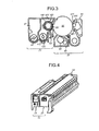
- a printer illustrated in Fig. 2 includes four image forming units 1Y, 1C, 1M, and 1K that generate toner images in yellow, cyan, magenta, and black (hereinafter, represented by Y, C, M, and K), respectively. These image forming units use toner in different colors of Y toner, C toner, M toner, and K toner as an image forming material for forming an image.
- the image forming units have the same configuration except for the toners.
- the image forming unit 1Y that generates a Y toner image will now be described as an example. As illustrated in Fig. 3 , the image forming unit 1Y includes a photosensitive element unit 2Y and a developing device 7Y.
- the photosensitive element unit 2Y and the developing device 7Y can be integrally attached to and detached from the printer main body as the image forming unit 1Y as illustrated in Fig. 4 . If the image forming unit 1Y is removed from the printer main body, the developing device 7Y can be attached to and detached from the photosensitive element unit 2Y.
- the photosensitive element unit 2Y includes a drum-shaped photosensitive element 3Y serving as an image carrier, a drum cleaning device 4Y, and a charging device 5Y, for example.
- the charging device 5Y uniformly charges (e.g., -690 V) the surface of the photosensitive element 3Y caused to rotate in the clockwise direction in Fig. 3 by a driving unit, which is not illustrated.
- Fig. 3 illustrates a method for charging the surface of the photosensitive element 3Y by applying a charging bias to a roller charging device 6Y adjacent to the photosensitive element 3Y.
- a charging brush method or a scorotron method may be employed.
- An optical writing unit 20 is arranged below the image forming units 1Y, 1C, 1M, and 1K.
- the optical writing unit 20 serving as a latent image forming unit irradiates the photosensitive elements 3Y, 3C, 3M, and 3K of the image forming units 1Y, 1C, 1M, and 1K, respectively, with laser light L based on image information.
- This irradiation lowers the surface potential (e.g., -50 V) only in the area exposed by the laser light L on the surfaces of the photosensitive elements, thereby forming electrostatic latent images for Y, C, M, and K on the photosensitive elements 3Y, 3C, 3M, and 3K, respectively.
- the surface potential e.g., -50 V
- the optical writing unit 20 deflects the laser light L output from a light source with a polygon mirror 21 driven to rotate by a motor to irradiate the photosensitive elements 3Y, 3C, 3M, and 3K with the laser light L via a plurality of optical lenses and mirrors.
- an optical writing unit that performs optical scanning with a light-emitting diode (LED) array may be employed.
- the electrostatic latent image formed on the surface of the photosensitive element moves to a developing area facing a developing roller 12Y of the developing device 7Y along with the rotation of the photosensitive element 3Y.
- the developing device 7Y includes a first developer circulating and conveying path 9Y and a second developer circulating and conveying path 14Y.
- the first developer circulating and conveying path 9Y is provided with a first conveying and stirring screw 8Y formed of a conveying screw and stirring fins and a toner supplying port, which is not illustrated.
- the second developer circulating and conveying path 14Y is provided with a second conveying and stirring screw 11Y formed of a conveying screw and stirring fins, a toner concentration sensor 10Y formed of a magnetic permeability sensor, the developing roller 12Y, and a doctor blade 13Y, for example.
- the developer circulating and conveying paths 9Y and 14Y are communicated with each other by communication ports on both ends (a front end and a rear end in Fig. 3 ) and contain a Y developer, which is not illustrated, composed of a negatively-charged Y toner and a magnetic carrier.
- the first conveying and stirring screw 8Y is rotated by a driving unit, which is not illustrated, to convey the Y developer in the first developer circulating and conveying path 9Y from the rear side to the front side in Fig. 3 .
- the Y developer conveyed to the front side moves to the second developer circulating and conveying path 14Y through the communication port on the front side.
- the second conveying and stirring screw 11Y rotates in the same manner to convey the Y developer entering the second developer circulating and conveying path 14Y from the front side to the rear side in Fig. 3 .
- the toner concentration of the Y developer being conveyed is detected by the toner concentration sensor 10Y fixed to the bottom of the second developer circulating and conveying path 14Y.
- the developing roller 12Y is arranged at an upper part of the second developer circulating and conveying path 14Y in a manner parallel to the second conveying and stirring screw 11Y.
- the developing roller 12Y is formed of a non-magnetic developing sleeve 15Y that rotates in the counterclockwise direction in Fig. 3 and a magnetic roller 16Y that is housed in the developing sleeve 15Y and that does not rotate. A part of the Y developer conveyed in the second developer circulating and conveying path 14Y is drawn up onto the surface of the developing sleeve 15Y by the magnetic force of the magnetic roller 16Y.
- the doctor blade 13Y is provided in a manner facing the developing sleeve 15Y with a fine gap interposed therebetween and restricts the thickness (drawn-up amount) of the Y developer thus drawn up when the Y developer passes by the doctor blade 13Y.
- the Y developer passing by the doctor blade 13Y is conveyed to the developing area facing the photosensitive element 3Y.
- the developing potential e.g., -550 V
- the surface potential e.g., -50 V
- the Y developer from which the Y toner is consumed by the development, is returned to the second developer circulating and conveying path 14Y and conveyed to the rear side in Fig. 3 by the second conveying and stirring screw 11Y, and then moves to the first developer circulating and conveying path 9Y through the communication port on the rear side.
- the Y developer returned to the first developer circulating and conveying path 9Y is supplied with toner from the toner supplying port, which is not illustrated, and is reconveyed to the front side in Fig. 3 by the first conveying and stirring screw 8Y.
- the detection result of the magnetic permeability of the Y developer obtained by the toner concentration sensor 10Y is transmitted to a control unit, which is not illustrated, as a voltage signal. Because the magnetic permeability of the Y developer correlates with the Y toner concentration in the Y developer, the toner concentration sensor 10Y outputs a voltage of a value corresponding to the Y toner concentration.
- the control unit described above includes a random access memory (RAM) and stores data, such as Vtref for Y, which is a target value of an output voltage received from the toner concentration sensor 10Y, and Vtref for C, Vtref for M, and Vtref for K, which are target values of output voltages from toner concentration sensors mounted on the other developing units, in the RAM.
- the value of the output voltage received from the toner concentration sensor 10Y is compared with Vtref for Y, and a Y toner supplying unit 130, which will be described later, is driven for a period of time corresponding to the comparison result.
- This drive supplies an appropriate amount of Y toner to the Y developer in which the Y toner is consumed along with the development and the Y toner concentration is reduced in the first developer circulating and conveying path 9Y.
- the Y toner concentration in the second developer circulating and conveying path 14Y is maintained within a predetermined range.
- Toner supply control similar to that described above is performed on developers in the image forming units (1C, 1M, and 1K) for the other colors.
- the Y toner image formed on the photosensitive element 3Y is intermediately transferred onto an intermediate transfer belt 81 illustrated in Fig. 2 .
- a waste toner remaining on the surface of the photosensitive element 3Y after the intermediate transfer is removed by the drum cleaning device 4Y.
- the drum cleaning device 4Y includes a cleaning blade 41Y serving as a cleaning member.
- the cleaning blade 41Y is supported in a counter manner with respect to a photosensitive element surface movement direction.
- the drum cleaning device 4Y further includes a waste toner collecting coil, which is not illustrated, that conveys the transfer residual toner scraped and collected by the cleaning blade 41Y to a waster toner bottle, which is not illustrated.
- a lubricant applying device is arranged on the downstream of the cleaning blade 41Y in the photosensitive element surface movement direction and on the upstream of the charging device 5Y in the photosensitive element surface movement direction.
- the lubricant applying device includes a brush roller 42Y serving as a lubricant supplying member, a solid lubricant (not illustrated) that is brought into contact with the brush roller 42Y and is made of zinc stearate, and a pressing spring that presses the solid lubricant against the brush roller 42Y.
- the brush roller 42Y also comes into contact with the surface of the photosensitive element 3Y and drives to rotate in the clockwise direction in Fig. 3 .
- the brush roller 42Y is a roller member obtained by winding a brush around a metal shaft.
- the brush roller 42Y scrapes off a lubricant from the solid lubricant with the brush portion thereof to apply the powder lubricant thus scraped off to the surface of the photosensitive element. While the lubricant used in the present embodiment is zinc stearate, it is not limited thereto.
- the lubricant applying device includes a lubricant leveling blade 43Y coming into contact with the surface of the photosensitive element 3Y on the downstream of the contact portion of the brush roller 42Y in the photosensitive element surface movement direction.
- the lubricant leveling blade 43Y is made of a polyurethane rubber and is supported in the counter manner.
- the photosensitive element 3Y from which the waste toner is removed and to which the lubricant is applied is neutralized by a neutralization device, which is not illustrated, and moves to the charging device 5Y to perform subsequent image formation.
- An image formation temperature sensor used in the printer according to the present embodiment is not illustrated.
- the image formation temperature sensor is arranged at a position where temperature detection highly correlating with the temperature of the developer in the developer circulating and conveying paths 9Y and 14Y can be performed, such as the inside of the developing device 7Y and a portion adjacent to the developing device 7Y in the image forming apparatus main body.
- a first paper cassette 31 and a second paper cassette 32 are provided below the optical writing unit 20 in Fig. 2 .
- a plurality of recording sheets P are housed in a stacked manner in each of the paper cassettes, and a first paper feeding roller 31a and a second paper feeding roller 32a come into contact with each uppermost recording sheet P.
- the paper feeding rollers 31a and 32a drive in the counterclockwise direction, thereby ejecting the uppermost recording sheet P in the paper cassettes 31 and 32 to a feed path 33.
- the recording sheet P is conveyed upward by a pair of carriage rollers 34 and temporarily stops at a position of a pair of registration rollers 35. Subsequently, the recording sheet P is conveyed to a secondary transfer nip (a contact point between a secondary transfer roller 50 and a secondary transfer facing roller 86) at an appropriate timing.
- a secondary transfer nip a contact point between a secondary transfer roller 50 and a secondary transfer facing roller 86
- a transfer unit 80 serving as a transferring unit that stretches and endlessly moves the intermediate transfer belt 81 in the counterclockwise direction in Fig. 2 is arranged above the image forming units 1Y, 1C, 1M, and 1K.
- the transfer unit 80 includes a belt cleaning unit 82, a first bracket 83, and a second bracket 84, for example.
- the transfer unit 80 includes four primary transfer rollers 85Y, 85C, 85M, and 85K, the secondary transfer facing roller 86, a driving roller 87, an auxiliary roller 88, and a tension roller 89, for example.
- the intermediate transfer belt 81 is endlessly moved in the counterclockwise direction in Fig. 2 by rotation drive of the driving roller 87 in a manner stretched around these eight rollers.
- the four primary transfer rollers 85Y, 85C, 85M, and 85K apply a transfer bias in a polarity (e.g., positive) opposite to the charging polarity of the toner from the back surface (inner circumferential surface of the loop) of the intermediate transfer belt 81.
- the intermediate transfer belt 81 is sequentially passing through the primary transfer nips for Y, C, M, and K along with the endless move, the Y toner image, the C toner image, the M toner image, and the K toner image on the photosensitive elements 3Y, 3C, 3M, and 3K, respectively, are primarily transferred onto the front surface of the intermediate transfer belt 81 in a superimposed manner.
- a four-color superimposed toner image (hereinafter, referred to as a four-color toner image) is formed on the intermediate transfer belt 81.
- the secondary transfer facing roller 86 and the secondary transfer roller 50 that is arranged at the outside of the loop of the intermediate transfer belt 81 sandwich the intermediate transfer belt 81 therebetween to form a secondary transfer nip.
- the recording sheet P sandwiched between the pair of registration rollers 35 is fed into the secondary transfer nip at a timing synchronized with the four-color toner image on the intermediate transfer belt 81.
- the four-color toner image on the intermediate transfer belt 81 is collectively secondarily transferred onto the recording sheet P in the secondary transfer nip by influences of a secondary transfer electric field generated between the secondary transfer roller 50 to which a secondary transfer bias is applied and the secondary transfer facing roller 86 and of nip pressure.
- the four-color toner image is formed as a full-color toner image in cooperation with the white color of the recording sheet P.
- a transfer residual toner that is not transferred onto the sheet P after passing through the secondary transfer nip and remains on the intermediate transfer belt 81 is removed by the belt cleaning unit 82.
- the belt cleaning unit 82 brings a cleaning blade 82a into contact with the front surface of the intermediate transfer belt 81, thereby scraping off and removing the transfer residual toner on the belt.
- a fixing unit 60 is provided above the secondary transfer nip.
- the fixing unit 60 is formed of a pressing and heating roller 61 housing a heat source 61a, such as a halogen lamp, and a fixing belt unit 62.
- the fixing belt unit 62 further includes a fixing belt 64 serving as a fixing member, a heating roller 63 housing a heat source 63a, such as a halogen lamp, a tension roller 65, and a driving roller 66, for example.
- the fixing belt 64 is rotated in the counterclockwise direction by the driving roller 66 and is heated and kept at a constant temperature (e.g., 140 degrees C) by the heating roller 63.
- the pressing and heating roller 61 rotates in the clockwise direction and is heated and kept at a constant temperature (e.g., 120 degrees C) by the heat source 61a inside thereof.
- the fixing belt 64 and the pressing and heating roller 61 come into contact with each other to form a fixing nip.
- the fixing belt 64 keeps its temperature constant in the following manner.
- a temperature sensor which is not illustrated, is arranged at the outside of the loop of the fixing belt 64 in a manner facing the front surface of the fixing belt 64 with a predetermined gap interposed therebetween.
- the temperature sensor detects the surface temperature of the fixing belt 64 just before entering the fixing nip.
- the detection result is transmitted to a fixing power supply circuit, which is not illustrated.
- the fixing power supply circuit Based on the detection result obtained by the temperature sensor, the fixing power supply circuit performs ON-OFF control of power supply to the heat source 63a housed in the heating roller 63 and the heat source 61a housed in the pressing and heating roller 61.
- the surface temperature of the fixing belt 64 is kept at 140 degrees C, for example.
- the recording sheet P that passes through the secondary transfer nip and on which the full-color toner image is formed is separated from the intermediate transfer belt 81 and is conveyed to the fixing nip in the fixing unit 60.
- the full-color toner image fixes onto the recording sheet P.
- the recording sheet P on which the toner image is fixed passes through a pair of ejecting rollers 67 and is discharged onto a discharge stacking unit 68 provided outside of the apparatus.
- toner bottles 19Y, 19C, 19M, and 19K that house the Y toner, the C toner, the M toner, and the K toner, respectively, are provided above the transfer unit 80.
- the toner in each color housed in the toner bottle 19 passes through a supplying path, which is not illustrated, and is supplied to the developing device 7 from the toner supplying port, which is not illustrated.
- the toner bottle 19 can be attached to and detached from the image forming apparatus main body independently of the image forming unit 1.
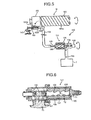
- Fig. 5 is an enlarged view of a configuration of a toner supplying unit 130.
- the toner bottle 19 serving as a toner container includes a bottle unit 191 that houses therein the toner and a cap unit 192 that engages with the head of the bottle unit 191 and holds the bottle unit 191 in a rotatable manner. If the toner bottle 19 is attached to the printer main body, a nozzle 142 is inserted into a hole 192b of the cap unit 192 in association with the attachment. At this time, a plug member 193 serving as an opening and closing member of the toner bottle 19 is sandwiched between the nozzle 142 and a claw member 145 to open a toner discharging port 192a (a powder discharging port). Thus, a toner receiving port (a powder receiving port) provided to the nozzle 142 and the toner discharging port 192a communicate with each other.
- a toner receiving port (a powder receiving port) provided to the nozzle 142 and the toner discharging
- the bottle unit 191 of the toner bottle 19 is formed in a nearly cylindrical shape and is provided with a helical projection 191a on the inner circumferential surface (corresponding to a helical groove viewed from the outer circumferential surface side). If the bottle unit 191 is driven to rotate in an arrow direction in Fig. 5 by a toner container driving unit, which is not illustrated, provided to the apparatus main body, the helical projection 191a transfers the toner housed in the bottle unit 191 to a space in the cap unit 192. As a result, the toner housed in the bottle unit 191 of the toner bottle 19 is conveyed into the nozzle 142 through the toner discharging port 192a.
- the other end of the nozzle 142 is connected to one end of a tube 139 serving as a toner supplying path.
- the tube 139 is made of a flexible material having excellent toner resistance, and the other end thereof is connected to a mono pump 131, which is a screw pump, serving as a toner supply unit of the toner supplying unit 130.
- a rubber material such as polyurethane, nitrile, ethylene propylene diene terpolymer (EPDM), and silicon
- a resin material such as polyethylene and nylon.
- the mono pump 131 is formed of a suction-type uniaxial eccentric screw pump and includes a rotor 135, a stator 132, a suction port 133, a driving shaft 134, and a motor 136, for example.
- the rotor 135, the stator 132, and the driving shaft 134, for example, are housed in a case, which is not illustrated.
- the stator 132 is a female screw member made of an elastic material, such as a rubber, and is provided with a double-pitched helical groove inside thereof.
- the rotor 135 is a male screw member made of a rigid material, such as a metal, with a helical groove formed on the outer circumferential surface thereof and is inserted through the stator 132 in a rotatable manner. One end of the rotor 135 is connected to the motor 136 via the driving shaft 134.
- the motor 136 drives to rotate the rotor 135 in the stator 132 in a predetermined direction, whereby a suction force is generated at the suction port 133 (the air in the tube 139 is discharged to generate negative pressure in the tube 139).
- the toner in the toner bottle 19 is sucked into the suction port 133 through the tube 139 together with the air.
- the toner sucked into the suction port 133 is transferred into a gap formed between the stator 132 and the rotor 135.
- the toner is then conveyed to the other end along with the rotation of the rotor 135 and is supplied to the inside of the developing device 7 via a toner conveying pipe 138.
- a hopper that temporarily houses therein the toner to be supplied to the developing device 7 may be provided between the mono pump 131 and the developing device 7.
- Fig. 6 illustrates a sectional view of the mono pump 131 used as the supplying unit in the present embodiment.
- the mono pump 131 includes the stator 132 in which a through hole 106 is formed, the rotor 135 arranged in the through hole 106 and driven to rotate, and the driving shaft 134 that drives to rotate the rotor 135, and these components are housed in a case 109.
- the through hole 106 is a double-pitched helical groove
- the rotor 135 is a single-pitched helical rod. Therefore, if the rotor 135 is arranged in the through hole 106, a gap G is formed.
- the gap G moves from the right to the left in Fig. 6 .
- suction pressure is generated at an entrance opening 120 of the through hole 106, that is, the toner suction side of the mono pump 131, thereby transferring the toner located at a position T1 into the gap G (T2).
- the toner is then conveyed to the left side, is discharged to a position T3 through an exit opening 121 of the through hole 106, and is supplied to the inside of the developing device 7.
- a crystalline polyester resin in the toner has a thermal fusion property that the viscosity rapidly decreases at around a fixing start temperature because of its crystallinity.
- the crystalline polyester resin shows excellent heat resistant storage stability just below a melting start temperature because of its crystallinity and rapidly reduces the viscosity at the melting start temperature (a sharp melt property) to get fixed. Therefore, it is possible to design toner having both excellent heat resistant storage stability and low-temperature fixability.
- the crystalline polyester resin shows an excellent result also in terms of a releasing width (difference between the minimum fixing temperature and a hot offset occurring temperature).
- the toner used in the present embodiment it is important for the toner used in the present embodiment to have a specific shape and a specific distribution of shape. If toner having an average circularity of smaller than 0.95 and an indeterminate shape significantly far from a spherical shape is used, satisfactory transferability and a high-quality image without toner scattering cannot be realized.
- an optical detection band method is suitably used. In the method, a suspension containing particles is passed through an image capturing unit detection band on a plate, and a particle image is optically detected and analyzed with a charge-coupled device (CCD) camera. It has been found that toner having an average circularity of 0.99 to 0.95 is effective in forming a high-definition image having reproducibility in an appropriate concentration.
- CCD charge-coupled device
- the average circularity is a value obtained by dividing the perimeter of an equivalent circle having an equal projected area obtained in the optical detection band method by the perimeter of an actual particle. It is more preferable that the average circularity be 0.99 to 0.96 and that the content of particles whose circularity is smaller than 0.96 be equal to or less than 10%.
- the toner contaminates a roller charging device that contacts to charge the photosensitive element, thereby preventing the roller charging device from exerting original chargeability, for example.
- the value can be measured by a flow-type particle image analyzer FPIA-2000 (manufactured by TOA Medical Electronics Co., Ltd.) as the average circularity.
- FPIA-2000 manufactured by TOA Medical Electronics Co., Ltd.
- 0.1 ml to 0.5 ml of a surfactant, preferably, of alkyl benzene sulfonate is added as a dispersant into 100 ml to 150 ml of water from which an impure solid is removed in advance in a container, and approximately 0.1 g to 0.5 g of a measurement sample is further added thereto.
- An ultrasonic disperser then performs dispersion processing on the suspension in which the sample is dispersed for approximately one to three minutes to make the concentration of dispersion liquid 3000 particles per microliter to 10000 particles per microliter. Subsequently, the shape and the distribution of the toner are measured by the device described above. Dv / Dn volume - average particle diameter / Number - average particle diameter
- a dry toner whose volume-average particle diameter (Dv) is 4 ⁇ m to 8 ⁇ m and whose ratio (Dv/Dn) of the volume-average particle diameter to the number-average particle diameter (Dn) is equal to or smaller than 1.25, preferably 1.05 to 1.20, is excellent in heat resistant storage stability, low-temperature fixability, and hot-offset resistance.
- the toner is used for a full-color copying machine, for example, excellent glossiness of an image can be achieved.
- fluctuation in the particle diameter of the toner in the developer is small even if consumption and supplying of the toner is performed for a long period of time.
- excellent and stable developability can be obtained.
- the toner is used for a one-component developer
- fluctuation in the particle diameter of the toner is small even if consumption and supplying of the toner is performed.
- excellent and stable developability and images can be obtained.
- a smaller particle diameter of the toner is more advantageous for realizing a high-resolution and high-quality image.
- a smaller particle diameter is disadvantageous for transferability and cleaning property.
- the toner is likely to be melt-adhered to the surface of a carrier in long-term stirring in the developing device to reduce the chargeability of the carrier.
- the toner is used for a one-component developer, filming of the developing roller with the toner and melt-adhesion of the toner to a toner-leveling member, such as a blade, are likely to occur.
- the particle diameter of the toner is larger than the range specified in the present embodiment, it is difficult to realize a high-resolution and high-quality image.
- the particle diameter of the toner is larger than the range specified in the present embodiment, it is difficult to realize a high-resolution and high-quality image.
- consumption and supplying of the toner is performed in the developer, fluctuation in the particle diameter of the toner is likely to increase.
- the ratio of the volume-average particle diameter to the number-average particle diameter is larger than 1.25.
- the toner may be preferably used in terms of stability in toner behavior and equalization in the charge amount. However, it has been found that the toner may fail to be charged sufficiently or the cleaning property may be deteriorated.
- Examples of a modified polyester resin (i) include polyester prepolymers modified by an isocyanate or an epoxy.
- the polyester prepolymer shows a chain-extending reaction with a compound containing an active hydrogen group (e.g., amines) to improve the releasing width (difference between the minimum fixing temperature and the hot offset occurring temperature).
- an active hydrogen group e.g., amines
- the modified polyester resin (i) can be readily prepared by, for example, reacting a well-known isocyanating agent or epoxidating agent with a polyester resin that is a base polymer.
- the isocyanating agent include aliphatic polyisocyanates (tetramethylene diisocyanate, hexamethylene diisocyanate, 2,6-diisocyanate methylcaproate, and the like); alicyclic polyisocyanates (isophorone diisocyanate, cyclohexylmethane diisocyanate, and the like); aromatic diisocyanates (tolylene diisocyanate, diphenylmethane diisocyanate, and the like); aromatic-aliphatic diisocyanates ( ⁇ , ⁇ , ⁇ ', ⁇ '-tetramethyl xylylene diisocyanate, and the like); isocyanurates; compounds that are prepared by blocking any of above-mentioned polyisocyanate
- the ratio of the isocyanating agent is represented by the equivalent ratio NCO/OH of an isocyanate group (NCO) to a hydroxy group (OH) of the polyester serving as the base polymer
- the ratio is usually 5/1 to 1/1, preferably 4/1 to 1.2/1, and more preferably 2.5/1 to 1.5/1. If NCO/OH exceeds 5, the low-temperature fixability deteriorates. If the molar ratio of NCO is smaller than 1, the urea content in the modified polyester is reduced, whereby the hot-offset resistance deteriorates.
- the amount of the isocyanating agent contained in the modified polyester resin is usually 0.5% by weight to 40% by weight, preferably 1% by weight to 30% by weight, and more preferably 2% by weight to 20% by weight.
- the amount of the isocyanating agent is smaller than 0.5% by weight, the hot-offset resistance deteriorates, and the composition is disadvantageous for trade-off between the heat resistant storage stability and the low-temperature fixability.
- the amount of the isocyanating agent exceeds 40% by weight, the low-temperature fixability deteriorates.
- the isocyanate group per molecule contained in the modified polyester resin is usually equal to or more than 1, preferably 1.5 to 3 on average, and more preferably 1.8 to 2.5 on average. If the isocyanate group per molecule is less than 1, the molecular weight of a urea modified polyester obtained after the chain-extending reaction is reduced, whereby the hot-offset resistance deteriorates.
- amines include diamine compounds, polyamine compounds of three-valent or higher; amino alcohol compounds; amino mercaptan compounds, amino acid compounds, and compounds obtained by blocking an amino group in any of above-mentioned amino compounds.
- diamine compounds include aromatic diamines (phenylene diamine, diethyl toluene diamine, 4,4'diamino diphenylmethane, and the like); alicyclic diamines (4,4'-diamino-3,3'dimethyl dicyclohexylmethane, diamine cyclohexane, isophorone diamine, and the like); and aliphatic diamines (ethylene diamine, tetramethylene diamine, hexamethylene diamine, and the like).
- aromatic diamines phenylene diamine, diethyl toluene diamine, 4,4'diamino diphenylmethane, and the like
- alicyclic diamines (4,4'-diamino-3,3'dimethyl dicyclohexylmethane, diamine cyclohexane, isophorone diamine, and the like
- aliphatic diamines ethylene diamine, t
- polyamine compounds of three-valent or higher examples include diethylene triamine and triethylene tetramine.
- amino alcohol compounds include ethanol amine and hydroxyethyl aniline.
- amino mercaptan compounds include aminoethyl mercaptan and aminopropyl mercaptan.
- amino acid compounds include aminopropionic acids and aminocaproic acids.
- Examples of the compounds that are prepared by blocking the amino group include ketimine compounds and oxazoline compounds that are prepared from the amine compounds and ketones (acetone, methyl ethyl ketone, methyl isobutyl ketone, and the like).
- ketimine compounds and oxazoline compounds that are prepared from the amine compounds and ketones (acetone, methyl ethyl ketone, methyl isobutyl ketone, and the like).
- preferable are diamine compounds and mixtures of a diamine compound and a small amount of polyamine compound.
- Amine compounds can be used as a crosslinking agent or a chain extender.
- molecular weight of a urea-modified polyester can be controlled by using a chain termination agent.
- chain termination agent include monoamines (diethyl amine, dibutyl amine, butyl amine, lauryl amine, and the like) and compounds obtained by blocking the above-mentioned monoamines (ketimine compounds).
- the ratio of the amines is represented by the equivalent ratio NCO/NH x of the isocyanate group (NCO) in the modified polyester resin to an amino group (NH x ) in the amines, the ratio is usually 1/2 to 2/1, preferably 1.5/1 to 1/1.5, and more preferably 1.2/1 to 1/1.2. If NCO/NH x exceeds 2 or is smaller than 1/2, the molecular weight of the urea modified polyester obtained after the chain-extending reaction is reduced, whereby the hot-offset resistance deteriorates.
- the urea modified polyester may contain both a urea bond and a urethane bond.
- the molar ratio of the urea bond content to the urethane bond content is usually 100/0 to 10/90, preferably 80/20 to 20/80, and more preferably 60/40 to 30/70. If the molar ratio of the urea bond is smaller than 10%, the hot-offset resistance deteriorates.
- the urea modified polyester obtained after the chain-extending reaction in the present embodiment is produced by a one-shot method or a prepolymer method.
- the weight-average molecular weight of the urea modified polyester is usually equal to or higher than ten thousand, preferably twenty thousand to ten million, and more preferably thirty thousand to one million. If the weight-average molecular weight is lower than ten thousand, the hot-offset resistance deteriorates.
- the number-average molecular weight of the urea modified polyester is not particularly restricted if a non-modified polyester, which will be described later, is used, and any number-average molecular weight that facilitates achieving of the weight-average molecular weight may be employed.
- the number-average molecular weight is usually lower than 20000, preferably 1000 to 10000, and more preferably 2000 to 8000. If the number-average molecular weight exceeds 20000, the low-temperature fixability and the glossiness obtained if the toner is used for a full-color apparatus deteriorate.
- a non-modified polyester resin (ii) may be contained as a toner binder component besides the urea modified polyester.
- (ii) in combination, the low-temperature fixability and the glossiness obtained if the toner is used for a full-color apparatus are improved.
- the urea modified polyester in combination rather than alone. It is preferable that at least a part of (i) and (ii) be compatibilized with each other in terms of the low-temperature fixability and the hot-offset resistance. Therefore, the polyester component of (i) and that of (ii) preferably have a similar composition.
- the peak molecular weight of (ii) is usually 1000 to 30000, preferably 1500 to 10000, and more preferably 2000 to 8000. If the peak molecular weight is lower than 1000, the heat resistant storage stability deteriorates. By contrast, if the peak molecular weight exceeds 10000, the low-temperature fixability deteriorates.
- the weight-average molecular weight of the non-modified polyester resin (ii) is preferably 2000 to 90000, and the glass-transition point (Tg) thereof is preferably 40 degrees C to 80 degrees C.
- the hydroxy value of (ii) is preferably equal to or more than 5, more preferably 10 to 120, and particularly preferably 20 to 80. If the hydroxy value is less than 5, it is disadvantageous in terms of trade-off between the heat resistant storage stability and the low-temperature fixability.
- the acid value of (ii) is usually 1 to 30 and preferably 5 to 20. With the acid value, the toner is likely to be negatively-charged. Furthermore, if the acid vale and the hydroxy value exceed these ranges, the toner is susceptible to the environment in a hot and humid environment and a cold and dry environment. As a result, an image is likely to deteriorate.
- a crystalline polyester resin (iii) is polyester having at least a melting point.
- a crystalline polyester resin that is synthesized by using a diol compound having 2 to 6 carbon atoms, particularly an alcohol component containing at least one of 1,4-butanediol, 1,6-hexanediol, and a derivative thereof and an acid component containing at least one of maleic acid, fumaric acid, succinic acid, and a derivative thereof and that has a repeated structure unit expressed by Chemical Formula (1):
- R 1 and R 2 represent hydrocarbon groups, the carbon number thereof is 1 to 20, and n represents a natural number.
- non-linear polyester is designed and used by adding a tri- or polyvalent alcohol, such as glycerin, as an alcohol component, adding a tri- or polyvalent carbonic acid, such as trimellitic anhydride, as an acid component, and performing condensation polymerization when synthesizing the polyester, for example.
- a tri- or polyvalent alcohol such as glycerin
- a tri- or polyvalent carbonic acid such as trimellitic anhydride
- the molecular structure of the crystalline polyester resin can be confirmed by solid nuclear magnetic resonance (NMR), for example.
- NMR solid nuclear magnetic resonance
- the molecular weight was fully examined in terms of the fact that a crystalline polyester resin having sharp molecular weight distribution and a low molecular weight is excellent in the low-temperature fixability.
- the peak position be within a range from 3.5 to 4.0, that the half width of the peak be equal to or smaller than 1.5, that the weight-average molecular weight (Mw) be 1000 to 6500, that the number-average molecular weight (Mn) be 500 to 2000, and that Mw/Mn be 2 to 5. It has been also found preferable that the melting temperature and the F1/2 temperature be as low as possible unless the heat resistant storage stability deteriorates and be within a range from 50 degrees C to 130 degrees C.
- the melting temperature and the F1/2 temperature are equal to or lower than 50 degrees C, the heat resistant storage stability deteriorates, and blocking is likely to occur because of the temperature in the developing device.
- the melting temperature and the F1/2 temperature are equal to or higher than 130 degrees C, the minimum fixing temperature is made higher, whereby the low-temperature fixability cannot be achieved.
- the longitudinal dispersion particle diameter of the crystalline polyester resin in the toner is preferably 0.2 ⁇ m to 3.0 ⁇ m.
- the acid value of the crystalline polyester resin is preferably equal to or higher than 8 mg KOH/g and more preferably 20 mg KOH/g to achieve a target low-temperature fixability.
- the acid value of the crystalline polyester resin is preferably equal to or lower than 45 mg KOH/g.
- the hydroxy value of a crystalline polymer is preferably 0 to 50 mg KOH/g and more preferably 5 to 50 mg KOH/g.
- (i)/(ii)+(iii) is usually 5/95 to 25/75, preferably 10/90 to 25/75, and more preferably 12/88 to 25/75.
- the weight ratio between (ii) and (iii) is 99/1 to 50/50, preferably 95/5 to 60/40, and more preferably 90/10 to 65/35. If the weight ratio is out of the range described above, the hot offset resistance deteriorates, and the composition is disadvantageous for trade-off between the heat resistant storage stability and the low-temperature fixability.
- the glass-transition point (Tg) of the toner binder serving as the toner base is preferably 40 degrees C to 70 degrees C and more preferably 40 degrees C to 55 degrees C. If the glass-transition point (Tg) of the toner binder is lower than 40 degrees C, the heat resistant storage stability deteriorates. By contrast, the glass-transition point (Tg) exceeds 70 degrees C, the low-temperature fixability becomes insufficient.
- the toner for forming an image according to the present embodiment tends to have excellent heat resistant storage stability even if the glass-transition point is low compared with a well-known polyester toner.
- the temperature (TG') at which the storage modulus is 10000 dyne/cm 2 at a measuring frequency of 20 Hz is usually equal to or higher than 100 degrees C and preferably 110 degrees C to 200 degrees C. If the temperature is lower than 100 degrees C, the hot-offset resistance deteriorates.
- the temperature (T ⁇ ) at which the viscosity is 1000 poise at a measuring frequency of 20 Hz is usually equal to or lower than 180 degrees C and preferably 90 degrees C to 160 degrees C. If the temperature exceeds 180 degrees C, the low-temperature fixability deteriorates. In other words, in terms of trade-off between the low-temperature fixability and the hot-offset resistance, it is preferable that TG' be higher than T ⁇ ).
- difference between TG' and T ⁇ (TG'-T ⁇ ) is preferably equal to or larger than 0 degrees C, more preferably equal to or larger than 10 degrees C, and particularly preferably equal to or larger than 20 degrees C. The upper limit of the difference is not particularly restricted.
- difference between TG' and T ⁇ is preferably 0 degrees C to 100 degrees C, more preferably 10 degrees C to 90 degrees C, and particularly preferably 20 degrees C to 80 degrees C.
- the peak of the molecular weight be within a range from 1000 to 30000, that the component having 30000 or more molecular weight be 1% by weight to 8% by weight, and that the number-average molecular weight be 2000 to 15000.
- the component having 1000 or less molecular weight be 0.1% by weight to 5.0% by weight.
- the THF-soluble components of the polyester resin contained in the toner be 1% by weight to 15% by weight.
- colorant examples include carbon blacks, nigrosine dyes, iron blacks, Naphthol Yellow S, Hansa Yellow (10G, 5G, and G), cadmium yellow, yellow iron oxide, yellow ochre, chrome yellow, titanium yellow, Polyazo Yellow, oil Yellow, Hansa yellow (GR, A, RN, R), Pigment Yellow L, Benzidine yellow (G and GR), Permanent Yellow (NCG), Vulcan Fast Yellow (5G and R), Tartrazine Lake, Quinoline Yellow Lake, Anthrazan Yellow BGL, Isoindolinone Yellow, red iron oxide, red lead, lead vermilion, cadmium red, cadmium mercury red, antimony vermilion, Permanent Red 4R, Para red, Fisay Red, parachloro-orthonitroaniline red, Lithol Fast Scarlet G, Brilliant Fast Scarlet, Brilliant Carmine BS, Permanent Red (F2R, F4R, FRL, FRLL and F
- the colorant used in the present embodiment can also be used as a master batch in which the colorant and a resin are compounded.
- binder resin used for preparing a master batch or for compounding with a master batch examples include, in addition to the above-mentioned modified and non-modified polyester resins, polymers of styrene and substituted styrenes such as polystyrenes, poly p-chlorostyrenes, and polyvinyltoluenes; styrene-based copolymers such as styrene-p-chlorostyrene copolymers, styrene-propylene copolymers, styrene-vinyltoluene copolymers, styrene-vinylnaphthalene copolymers, styrene-methyl acrylate copolymers, styrene-ethyl acrylate copolymers, styrene-butyl acrylate copolymers, styrene-octyl acrylate copoly
- the master batch described above can be obtained by mixing and kneading a resin for a master batch and a colorant while applying a high shearing force.
- an organic solvent can be used to promote interaction between the colorant and the resin.
- a method called a flushing method is preferably used because a wet cake of the colorant can be used without any change and need not be dried.
- a water-based paste containing water of a colorant is mixed and kneaded together with a resin and an organic solvent, the colorant is transferred to the resin, and the water and the organic solvent component are removed.
- a high shearing force dispersing device such as a three roll mill, is preferably used.
- a wax may be included in addition to the toner binder and colorant. Any known waxes can be used as a wax for the present embodiment. Examples of the waxes include polyolefin waxes (polyethylene waxes, polypropylene waxes, and the like); long chain hydrocarbons (paraffin waxes, sasol waxes, and the like); and waxes containing a carbonyl group. Among these, waxes containing a carbonyl group are preferable.
- waxes containing a carbonyl group examples include polyalkanoic acid esters (carnauba wax, montan wax, trimethylolpropane tribehenate, pentaerythritol tetrabehenate, pentaerythritol diacetate dibehenate, glycerin tribehenate, 1,1,8-octadecanediol distearate, and the like); polyalkanol esters (tristearyl trimellitate, distearyl maleate, and the like); polyalkanoic acid amides (ethylenediamine dibehenylamide and the like); polyalkylamide (trimellitic acid tristearylamide and the like); and dialkylketones (distearyl ketone and the like).
- polyalkanoic acid esters are preferable.
- the melting point of the wax in the present embodiment is usually 40 degrees C to 160 degrees C, preferably 50 degrees C to 120 degrees C, and more preferably 60 degrees C to 90 degrees C.
- a wax having a melting point of lower than 40 degrees C negatively affects the heat resistant storage stability.
- a wax having a melting point of higher than 160 degrees C is likely to cause cold offset in fixing at a low temperature.
- the melt viscosity of the wax is preferably 5 cps to 1000 cps and more preferably 10 cps to 100 cps as a measured value at a temperature higher than the melting point by 20 degrees C.
- a wax whose melt viscosity exceeds 1000 cps does not have much effect to improve the hot offset resistance and the low-temperature fixability.
- the amount of the wax contained in the toner is usually 0% by weight to 40% by weight and preferably 3% by weight to 30% by weight.
- Toner for the present embodiment may include a charge control agent, if necessary. All the known charge control agents can be used. Examples of charge control agent include nigrosine-based dyes, triphenylmethane-based dyes, chromium containing metal complex dyes, molybdic acid chelate pigments, rhodamine-based dyes, alkoxy-based amines, quaternary ammonium salts (including fluorine modified quaternary ammonium salts), alkylamides, phosphorus elements or phosphorus compounds, tungsten metal or tungsten compounds, fluorine-based activating agents, metal salts of salicylic acid, and metal salts of salicylic acid derivatives.
- charge control agent include nigrosine-based dyes, triphenylmethane-based dyes, chromium containing metal complex dyes, molybdic acid chelate pigments, rhodamine-based dyes, alkoxy-based amines, quaternary ammonium
- charge control agent examples include BONTORON 03 that is a nigrosine-based dye, BONTORON P-51 that is a quaternary ammonium salt, BONTORON S-34 that is a metal containing azo dye, E-82 that is a metal complex compound of oxynaphthoic acid, E-84 that is a metal complex compound of salicylic acid and E-89 that is a phenol-based condensate (all are manufactured by Orient Chemical); TP-302 and TP-415 each of which is a molybdenum complex compound of a quaternary ammonium salt (both are manufactured by Hodogaya Chemical Industries Co., Ltd.); Copy Charge PSY VP2038 that is a quaternary ammonium salt, Copyblue PR that is a triphenylmethane derivative, Copy Charge NEG VP 2036 and Copy Charge NX VP434 that are quaternary ammonium salt (all manufactured by Hoechst AG); LRA-901,
- the amount of the charge control agent in the present embodiment is determined based on the type of binder resin, presence of an additive used as necessary, and the method for producing the toner including the dispersion method and is not uniquely restricted.
- the charge control agent is preferably used within a range from 0.1 parts by weight to 10 parts by weight per 100 parts by weight of the binder resin. More preferably, the charge control agent is used within a range from 0.2 parts by weight to 5 parts by weight. If the amount of the charge control agent exceeds 10 parts by weight, the chargeability of the toner is made too large, thereby reducing advantageous effects of a main charge control agent. Thus, electrostatic attraction to the developing roller increases, resulting in reduction in the fluidity of the developer and reduction in image density.
- the charge control agent may be melted and kneaded together with the master batch and the resin before being dissolved and dispersed, may be added directly to the organic solvent when being dissolved and dispersed, or may be fixed to the surface of the toner after the toner particles are created.
- any resin can be used as long as it can form an aqueous dispersion, and it may be a thermoplastic resin or a thermosetting resin.
- the resins include vinyl resins, polyurethane resins, epoxy resins, polyester resins, polyamide resins, polyimide resins, silicon resins, phenol resins, melamine resins, urea resins, aniline resins, ionomer resins, and polycarbonate resins. Two or more of these resins may be used in combination.
- vinyl resins, polyurethane resins, epoxy resins, polyester resins and combination thereof are preferable because these resins can readily form an aqueous dispersion of fine, spherical resin particles.
- Vinyl resins are polymers obtained by polymerizing or copolymerizing a vinyl monomer, and examples thereof include styrene-(meth)acrylic ester resins, styrene-butadiene copolymers, (meth)acrylic acid-acrylic acid ester polymer, styrene-acrylonitrile copolymers, styrene-maleic anhydride copolymers, and styrene-(meth)acrylic acid copolymers.
- the volume average particle size of the resin fine particles are preferably 5 nm to 500 nm.
- inorganic fine particles are preferably used as external additives for enhancing the fluidity and electrostatic property of the colored particles of the present embodiment.
- the volume average particle size of the inorganic particles is 30 nm to 100 nm.
- Specific examples of the inorganic fine particles include silica, alumina, titanium oxide, titanium barium, titanium magnesium, titanium calcium, titanium strontium, zinc oxide, tin oxide, silica sand, clay, mica, tabular spar, diatom earth, chromium oxide, cerium oxide, red iron oxide, antimony trioxide, magnesium oxide, zirconium oxide, barium sulfate, barium carbonate, calcium carbonate, silicon carbide, and silicon nitride.
- the external additives include polymer fine particles of, for example: polystyrenes obtained by soap-free emulsion polymerization, suspension polymerization, or dispersion polymerization; copolymers of methacrylic acid esters and acrylic acid esters; polycondensates such as silicone, benzoguanamine, and nylons; and polymer particles of thermosetting resins.
- plasticizers can prevent deterioration of flow characteristics and electrostatic characteristics even in a highly humid atmosphere by improving hydrophobicity of particles through a surface treatment.
- preferable surface treating agent include silane coupling agents, silylating agents, silane coupling agents containing a fluorinated alkyl group, organic titanate-based coupling agents, aluminum-based coupling agents, silicone oils, and modified silicon oils.
- cleaning property improving agents for removing developer remaining on a photosensitive element or a primary transfer medium after transferring include: metal salts of a fatty acid such as zinc stearate, calcium stearate, and stearic acid; and polymer fine particles obtained by, for example, soap-free emulsion polymerization, such as polymethyl methacrylate fine particles and polystyrene fine particles.
- polymer fine particles have a relatively narrow particle size distribution and volume average particle size of 0.01 ⁇ m to 1 ⁇ m.
- the toner binder serving as the toner base can be produced by the following method, for example.
- Polyol (1) and polycarboxylic acid (2) are heated to 150 degrees C to 280 degrees C in the presence of a well-known esterification catalyst, such as tetrabutoxy titanate and dibutyltin oxide, and generated water is removed while reducing the pressure as needed to obtain polyester containing a hydroxy group.
- a well-known esterification catalyst such as tetrabutoxy titanate and dibutyltin oxide
- polyisocyanate (3) is reacted with the polyester at a temperature from 40 degrees C to 140 degrees C to obtain prepolymer (A) containing an isocyanate group.
- amines (B) is reacted with (A) at a temperature from 0 degrees C to 140 degrees C to obtain polyester modified by a urea bond.
- a solvent may be used as needed.
- Solvents that can be used are those inactive to isocyanate (3). Examples thereof include aromatic solvents (toluene, xylene, and the like); ketones (acetone, methyl ethyl ketone, methyl isobutyl ketone, and the like); esters (ethyl acetate and the like); amides (dimethyl formamide, dimethylacetamide, and the like); and ethers (tetrahydrofuran and the like).
- aromatic solvents toluene, xylene, and the like
- ketones acetone, methyl ethyl ketone, methyl isobutyl ketone, and the like
- esters ethyl acetate and the like
- amides dimethyl formamide, dimethylacetamide, and the like
- ethers tetrahydrofuran and the like.
- dry toner according to the present embodiment can be produced by the following method, the production method is not limited thereto.
- the aqueous medium used in the present embodiment may be water alone or a mixture of water and water miscible solvent.
- water miscible solvent include alcohols (methanol, isopropanol, ethylene glycol, and the like); dimethyl formamide, tetrahydrofuran, cellosolves (methyl cellosolve, and the like); and lower ketones (acetone, methyl ethyl ketone, and the like).
- the toner particles may be formed by reacting a dispersion composed of the prepolymer (A) containing an isocyanate group with (B) in the aqueous medium or using the urea modified polyester (i) produced in advance.
- a composition of toner materials composed of the urea modified polyester (i) or the prepolymer (A) is added in the aqueous medium, and the composition is dispersed by a shearing force, for example.
- the prepolymer (A) and other toner compositions may be mixed together when the dispersion is formed in the aqueous medium.
- the toner materials may be mixed together in advance and that the mixture thus obtained be added and dispersed in the aqueous medium.
- the other toner materials such as the colorant, the mold releasing agent, and the charge control agent, are not necessarily mixed when the particles are formed in the aqueous medium but may be added after the particles are formed. After particles containing no colorant are formed, the colorant may be added using a well-known dyeing method, for example.
- the method for dispersion is not particularly restricted, well-known equipment can be applied, such as a low-speed shearing device, a high-speed shearing device, a friction device, a high-pressure jet device, and an ultrasonic device.
- a high-speed shearing device is preferably used to make the particle diameter of the dispersion 2 ⁇ m to 20 ⁇ m. If a high-speed shearing disperser is used, the rotation rate thereof is not particularly restricted. The rotation rate is usually 1000 rpm to 30000 rpm and preferably 5000 rpm to 20000 rpm. While a period of time for dispersion is not particularly restricted, it is usually 0.1 minutes to 5 minutes in a batch method.
- a temperature for dispersion is usually 0 degrees C to 150 degrees C (under pressure) and preferably 40 degrees C to 98 degrees C.
- a higher temperature is preferably employed because the higher temperature lowers the viscosity of the urea modified polyester (i) and the dispersion composed of the prepolymer (A), thereby facilitating the dispersion.
- the amount of the aqueous medium per 100 parts of the toner composition containing the urea modified polyester (i) or the prepolymer (A) is usually 50 parts by weight to 2000 parts by weight and more preferably 100 parts by weight to 1000 parts by weight. If the amount of the aqueous medium is less than 50 parts by weight, the dispersed state of the toner composition deteriorates, whereby no toner particle having a predetermined particle diameter can be obtained. By contrast, if the amount of the aqueous medium exceeds 20000 parts by weight, it is not economical. Furthermore, a dispersant may be used as needed. It is preferable to use the dispersant in terms of sharpness in the particle size distribution and stability in the dispersion.
- the amines (B) may be added and reacted with the prepolymer (A) before the toner composition is dispersed in the aqueous medium, or the amines (B) may be added after the toner composition is dispersed in the aqueous medium to cause a reaction from the particle interface.
- the urea modified polyester is preferentially generated on the surface of the toner to be produced, whereby it is possible to generate a concentration gradient inside of the particles.
- anionic surfactants such as alkylbenzene sulfonates, ⁇ -olefin sulfonates, phosphorus esters
- cationic surfactants of amine salt type such as alkyl amine salts, amino alcohol fatty acid derivatives, polyamine fatty acid derivatives, and imidazoline or of quaternary ammonium salt type such as alkyltrimethylammonium salts, dialkyldimethylammonium salts, alkyldimethylbenzylammonium salts, pyridinium salts, alkylisoquinolinium salts, and benzetonium chloride
- nonionic surfactants such as fatty acid amide derivatives and polyalcohol derivatives
- amphoteric surfactants such as alan
- surfactant having a fluoroalkyl group examples include C 2-10 fluoroalkyl carboxylic acid and metal salts thereof, disodium perfluorooctanesulfonylglutamate, sodium 3- [omega-fluoroalkyl(C 6-11 )oxy]-1-alkyl(C 3-4 )sulfonate, sodium 3 [omega-fluoroalkanoyl(C 6-8 )-N-ethylamino)-1-propanesulfonate, fluoroalkyl(C 11-20 )carboxylic acid and metal salts thereof, perfluoroalkyl carboxylic acid(C 7-13 ) and metal salts thereof, perfluoroalkyl(C 4-12 )sulfonic acid and metal salts thereof, perfluorooctane
- anionic surfactant examples include: Surflon S-111, S-112, and S-113 (manufactured by Asahi Glass Co., Ltd.); Fluorad FC-93, FC-95, FC-98, and FC-129 (manufactured by Sumitomo 3M limited); Unydine DS-101 and DS-102 (manufactured by Daikin Industries, Ltd.); Megaface F-110, F-120, F-113, F-191, F-812, and F-833 (manufactured by DIC Corporation); Eftop EF-102, 103, 104, 105, 112, 123A, 123B, 306A, 501, 201, and 204 (manufactured by Tochem Products Co., Ltd); and Ftergent F-100 and F150 (manufactured by Neos Company limited).
- cationic surfactant examples include aliphatic primary, secondarily, or secondary amine acid containing a fluoroalkyl group, aliphatic quaternary ammonium salt, such as perfluoroalkyl (C6-C10) sulfonamide propyltrimethyl ammonium salt, benzalkonium salt, benzethonium chloride, pyridium salt, and imidazolinium salt.
- aliphatic primary, secondarily, or secondary amine acid containing a fluoroalkyl group examples include aliphatic quaternary ammonium salt, such as perfluoroalkyl (C6-C10) sulfonamide propyltrimethyl ammonium salt, benzalkonium salt, benzethonium chloride, pyridium salt, and imidazolinium salt.
- Examples of the trade name of the cationic surfactant include Surflon S-121 (manufactured by Asahi Glass Co., Ltd.), Fluorad FC-135 (manufactured by Sumitomo 3M limited); Unydine DS-202 (manufactured by Daikin Industries, Ltd.), Megaface F-150, and F-824 (manufactured by DIC Corporation), Eftop EF-132, (manufactured by Tochem Products Co., Ltd), and Ftergent F-300 (manufactured by Neos Company limited).
- Surflon S-121 manufactured by Asahi Glass Co., Ltd.
- Fluorad FC-135 manufactured by Sumitomo 3M limited
- Unydine DS-202 manufactured by Daikin Industries, Ltd.
- Megaface F-150, and F-824 manufactured by DIC Corporation
- Eftop EF-132 manufactured by Tochem Products Co., Ltd
- Ftergent F-300 manufactured by Neos Company limited
- tricalcium phosphate, calcium carbonate, titanium oxide, colloidal silica, and hydroxyapatite can be used as a poorly water-soluble inorganic compound dispersant, for example.
- the dispersion drops may be stabilized with a polymer protective colloid.
- polymer protective colloids include homopolymers and copolymers of the following compounds: acids such as acrylic acid, methacrylic acid, ⁇ -cyanoacrylic acid, ⁇ -cyanomethacrylic acid, itaconic acid, crotonic acid, fumaric acid, maleic acid, and maleic anhydride; (meth)acrylic monomers having a hydroxy group such as ⁇ -hydroxyethyl acrylate, ⁇ -hydroxyethyl methacrylate, ⁇ -hydroxypropyl acrylate, ⁇ -hydroxypropyl methacrylate, ⁇ -hydroxypropyl acrylate, ⁇ -hydroxypropyl methacrylate, 3-chloro-2-hydroxypropyl acrylate, 3-chloro-2-hydroxypropyl methacrylate, diethylene glycol monoacrylic acid esters, diethylene glycol monomethacrylic acid esters, glycerin monoacrylic acid esters, gly
- the calcium phosphate salt is removed from fine particles by dissolving the calcium phosphate salt with an acid of hydrochloric acid and washing away the calcium phosphate salt, for example.
- the calcium phosphate salt can also be removed by enzymatic decomposition, for example.
- the dispersant may remain on the surface of the toner particles. However, it is preferable to wash and remove the dispersant after at least one of a chain-extending reaction and a cross-linking reaction in terms of the chargeability of the toner.
- a solvent capable of dissolving the urea modified polyester (i) and the prepolymer (A) may be used. It is preferable to use the solvent in terms of sharpness in the particle size distribution.
- the solvent preferably volatizes at a boiling point of lower than 100 degrees C in terms of facilitation of its removal.
- solvents examples include toluene, xylene, benzene, carbon tetrachloride, methylene chloride, 1,2-dichloroethane, 1,1,2-trichloroethane, trichloroethylene, chloroform, monochlorobenzene, dichlorloethylidene, methyl acetate, ethyl acetate, methyl ethyl ketone, and methyl isobutyl ketone. These solvents may be used alone or in combination.
- Particularly aromatic solvents such as toluene and xylene and halogenated hydrocarbons such as methylene chloride, 1,2-dichloroethane, chloroform, and carbon tetrachloride are preferable.
- the amount of the solvent is generally 0 to 300 parts, preferably 0 to 100 parts, more preferably 25 to 70 parts per 100 parts of the prepolymer (A).
- a solvent is used, after extension and/or crosslinking reaction, the solvent is removed under normal or reduced pressure at an elevated temperature.
- a period of time for at least one of the chain-extending reaction and the cross-linking reaction is determined depending on the reactivity in combination of the isocyanate group structure contained in the prepolymer (A) and the amines (B).
- the period of time is usually 10 minutes to 40 hours and preferably 2 hours to 24 hours.
- a temperature for the reaction is usually 0 degrees C to 150 degrees C and preferably 40 degrees C to 98 degrees C.
- a well-known catalyst may be used as needed. Examples of the catalyst include dibutyltin laurate and dioctyltin laurate.
- a method can be employed in which the temperature of the whole system is gradually increased to completely evaporate and remove the organic solvent from drops.
- a water-insoluble organic solvent in drops may be completely removed to form toner fine particles, and an aqueous dispersant may also be evaporated and removed.
- the dry atmosphere into which the emulsified dispersion is sprayed include a gas obtained by heating air, nitrogen, carbon dioxide, and combustion gas, and particularly used are various types of air currents heated to a temperature equal to or higher than a boiling point of a solvent in use having the highest boiling point.
- Short-time treatment performed by a spray dryer, a belt dryer, a rotary kiln, and the like can achieve a target quality sufficiently. If the particle size distribution in emulsification dispersion is wide and the washing and drying treatment is performed while maintaining the particle size distribution, the particle size distribution can be adjusted by classifying the particle sizes into a desired particle size distribution.
- the fine particle part in the liquid can be removed by a cyclone, a decanter, a centrifugal separator, and the like. While the classification may be performed on the toner obtained as a powder after drying process, it is preferable to perform the classification in the liquid in terms of efficiency.
- the unnecessary fine particles or coarse particles thus obtained can be returned to the kneading process and be used for forming particles again. At this time, the fine particles or the coarse particles may be in a wet state.
- the used dispersant be removed from the dispersion liquid thus obtained as much as possible.
- the removal is preferably performed along with the classification described above.
- the toner powder obtained after the drying process By mixing the toner powder obtained after the drying process and dissimilar particles, such as mold releasing agent fine particles, charge controllable fine particles, fluidizer fine particles, and colorant fine particles, and by applying a mechanical shock to the powder thus mixed, the toner powder and the dissimilar particles can be fixed and fused on the surface. As a result, it is possible to prevent the dissimilar particles from desorbing from the surface of the complex particles thus obtained.
- dissimilar particles such as mold releasing agent fine particles, charge controllable fine particles, fluidizer fine particles, and colorant fine particles
- Examples of the specific method include a method for applying a shock to the mixture with blades rotating at high speed and a method for injecting the mixture into a high-speed air current to accelerate the mixture and causing the particles or complex particles to collide with a suitable collision board.
- Examples of the specific device include Ongmill (manufactured by Hosokawa Micron Corporation), a device obtained by modifying I-type mill (Nippon Pneumatic Mfg. CO., Ltd.) such that crushing air pressure is reduced, Hybridization system (manufactured by Nara Machinery Co., Ltd.), Kryptron system (manufactured by Kawasaki Heavy Industries, Ltd.), and an automatic mortar.
- the toner be produced using a crystalline polyester resin dispersion liquid having a volume-average particle diameter of 0.2 ⁇ m to 3 ⁇ m.
- the toner simply needs to be used in a manner mixed with a magnetic carrier.
- the content ratio of the toner to the carrier in the developer is preferably one part by weight to 10 parts by weight of the toner per 100 parts by weight of the carrier.
- any conventionally-known carrier such as ion powder having a particle diameter of around 20 to 200 ⁇ m, ferrite powder, magnetite powder, and magnetic resin carrier can be used.
- the covering material include amino resins such as urea-formaldehyde resins, melamine resins, benzoguanamine resins, urea resins, polyamide resins and epoxy resins.
- polyvinyl or polyvinylidene resins such as acrylic resins, polymethyl methacrylate resins, polyacrylonitrile resins, polyvinyl acetate resins, polyvinyl alcohol resins, polyvinyl butyral resins, polystyrene-based resins such as polystyrene resins and styrene-acrylic acid copolymers; halogenated olefin resins such as polyvinyl chloride resins; polyester resins such as polyethylene terephthalate resins and polybutylene terephthalate resins; polycarbonate resins; polyethylene resins; polyvinylidene fluoride resins; polytrifluoroethylene resins; polyhexafluoropropylene resins; copolymers of vinylidene fluoride and acrylic monomer; copolymers of vinylidene fluoride and vinyl fluoride; terpolymers of tetrafluoroethylene, vinyliden
- a conductive powder and the like may be contained in the coating resin as needed.
- the conductive powder include a metal powder, carbon black, titanium oxide, tin oxide, and zinc oxide.
- the conductive powder preferably has an average particle diameter of equal to or smaller than 1 ⁇ m. If the average particle diameter is larger than 1 ⁇ m, control of electric resistance is made difficult.
- the toner according to the present embodiment may also be used as a one-component magnetic toner using no carrier or a non-magnetic toner.
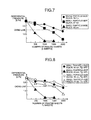
- Fig. 7 is a graph that plots differential pressure (suction pressure) of the mono pump 131 against driving time (corresponding to the number of printed sheets at an image area ratio of 5%) of the mono pump 131.
- silica with a particle diameter of 22 nm
- silica also referred to as small particle-size silica
- the supplying capacity of the mono pump 131 decreases when 300 thousand to 400 thousand sheets are printed.
- the particle diameter of the small particle-size silica increases, the supplying capacity is less likely to decrease.
- small particle-size silica with a particle diameter of 35 nm it has been confirmed that sufficient supplying capacity can be maintained even if 1.5 million or more sheets are printed.
- the silica serving as the inorganic fine particles serving as the inorganic fine particles to be externally added to the toner, it is possible to enhance a spacer effect of the silica to prevent the toners or the toner and the rotor 135 from directly coming into contact with each other. As a result, adhesion of the toner to the rotor 135 of the mono pump 131 can be suppressed.
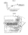
- Fig. 1 is a graph that plots the life of the mono pump 131 against the particle diameter of the small particle-size silica based on the data of Fig. 7 .
- the particle diameter of the small particle-size silica simply needs to be equal to or larger than 30 nm to achieve 1.5 million sheets of printing, which is a target life of the mono pump 131.
- the toner is less likely to adhere to the rotor 135, but reduction in the fluidity of the toner occurs as a side effect. If the fluidity is reduced, the tube of the supplying path is likely to be clogged up with the toner, resulting in poor supplying, or the toner supplied in the developing device 7 becomes difficult to be mixed in the developer. If the dispersibility of the supplied toner is poor, the toner is drawn up onto the developing sleeve without being charged sufficiently. As a result, problems such as a stain and toner scattering in the apparatus may occur.
- Table 1 lists evaluation results of tube clogging in which the tube 139 of the toner supplying unit 130 is clogged up with the toner, which is one of side effects that can occur because of an increase in the particle diameter of the small particle-size silica.
- small particle-size silica with a particle diameter of equal to or smaller than 100 nm is preferably used to prevent tube clogging in an operation-guaranteed environment (because small particle-size silica with a particle diameter of 120 nm barely meets the conditions, a particle diameter of 100 nm is employed so as to leave a margin).
- Fig. 8 is a graph illustrating transition in the differential pressure of the mono pump 131 based on combinations of the particle diameter of the small particle-size silica and the glass-transition point (Tg).
- Fig. 8 two types of toner binders, which is the toner base, having a glass-transition point Tg of 50 degrees C and a glass-transition point Tg of 60 degrees C were prepared, and small particle-size silica with a volume-average particle diameter of 22 nm and a volume-average particle diameter of 35 nm were externally added to each of the toner binders, thereby obtaining four types of toners. Subsequently, transition in the differential pressure of the mono pump 131 for each toner was shown graphically.
- Fig. 9 is a graph illustrating a relationship between the life of the mono pump and occurrence of image defects such as a white dot (hereinafter, referred to as "spotty stain") with respect to the additive amount of the small particle-size silica.
- spotty stain a white dot
- toners at five levels of additive amounts of the small particle-size silica from 0 parts to 4.0 parts were prepared.
- driving time in which differential pressure of equal to or higher than 1.5 kpa can be maintained is converted into the number of printed sheets, and a life of equal to or larger than 1.5 million sheets was determined to be acceptable.
- the cleaning blade 41, the lubricant, and the brush roller 42 which is a lubricant applying brush, degraded in advance by printing of the number of sheets equivalent to the life of the image forming unit 1 and using a new photosensitive element 3 and a new roller charging device 6, ranking evaluation is made for the incidence of spotty stain on the photosensitive element when 2500 sheets of entire solid images are printed.
- the spacer effect to widen a gap between toners is enhanced, thereby reducing adhesion of the toner to the rotor 135 of the mono pump 131. It has been confirmed that equal to or more than 1.0 part of the small particle-size silica needs to be added to allow the number of sheets equivalent to the life of the mono pump 131 to exceed 1.5 million.
- the toner used in the present embodiment preferably has a volume-average particle diameter of 4 ⁇ m to 8 ⁇ m and an average circularity of 0.99 to 0.95. While detailed evaluation results are omitted, it has been confirmed that the volume-average particle diameter of the toner needs to be equal to or smaller than 8 ⁇ m in terms of improvement in the reproducibility of thin lines and needs to be equal to or larger than 4 ⁇ m in terms of cleaning blade durability evaluation for the photosensitive element and the intermediate transfer belt and of carrier chargeability reduction evaluation (spent evaluation) in continuous printing of high-quality images. Furthermore, it has been confirmed that the average circularity of the toner needs to be equal to or lower than 0.99 in terms of similar cleaning blade durability evaluation and needs to be equal to or higher than 0.95 in terms of transfer blur and toner scattering evaluation.
- the additive amount of the zinc stearate to be added to the tonner is preferably equal to or smaller than 0.30% by weight.
- Spotty stain caused by an increase in the additive amount of inorganic fine particles occurs as follows: inorganic fine particles released from the toner adhere to the surface of each photosensitive element 3 serving as an image carrier; the inorganic fine particles further adhere to grow up on the adhered material; and an image with white dots is formed.
- the following method can be employed to suppress occurrence of spotty stain.
- a lubricant used in mixture as the lubricant (solid lubricant) to be applied to each photosensitive element 3 serving as an image carrier with the lubricant applying device are a fatty acid metal salt (A) and an inorganic lubricant (B) spreading out uniformly and swiftly on the surface of the image carrier to protect the surface of the image carrier and adding lubricity for protecting the blade.
- A fatty acid metal salt
- B inorganic lubricant
- lubricant described above makes it possible to protect each photosensitive element 3 and to suppress abrasion of the cleaning blade 41 of each drum cleaning device 4. As a result, it is possible to extend the life of each image forming unit 1.
- using the lubricant described above makes it possible to increase the number of sheets on which printing can be performed by each image forming unit 1 before spotty stain occurs.
- fatty acid metal salts include barium stearate, lead stearate, iron stearate, nickel stearate, cobalt stearate, copper stearate, strontium stearate, calcium stearate, cadmium stearate, magnesium stearate, zinc stearate, zinc oleate, magnesium oleate, iron oleate, cobalt oleate, copper oleate, lead oleate, manganese oleate, zinc palmitate, cobalt palmitate, lead palmitate, magnesium palmitate, aluminum palmitate, calcium palmitate, lead caprylate, lead caprate, zinc linolenate, cobalt linolenate, calcium linolenate, zinc ricinoleate, cadmium ricinoleate and mixture thereof, but not limited thereto. These compounds can be used as a mixture. In the present embodiment, zinc stearate is the most preferable because it exhibits excellent film forming properties
- Zinc stearate is excellent in uniform film-forming property but has a problem with cleaning property.
- a blade cleaning method is employed as a method for removing a waste toner remaining on the surface of the photosensitive element 3 after intermediate transfer.
- zinc stearate has a property of facilitating the toner's passing by the cleaning blade 41. If the toner passes by the cleaning blade 41, the toner directly appears on an image or further contaminates the roller charging device 6 serving as a charging member. The passing-by of the toner becomes more remarkable as the particle diameter of the toner is smaller. In addition, frequent passing-by of the toner and the like abrades the cleaning blade 41, thereby shortening the life of each image forming unit 1.
- the inorganic lubricant (B) has a function to make up for such defects of zinc stearate. Therefore, by using the inorganic lubricant (B) in mixture, a particularly excellent protective effect can be achieved in the present embodiment.
- the inorganic lubricant (B) is an inorganic compound that cleaves to lubricate or provides internal lubrication.
- the specific substance include talc, mica, boron nitride, molybdenum disulfide, tungsten disulfide, kaolin, smectite, hydrotalcite compounds, calcium fluoride, graphite, plate-like alumina, sericite, and synthetic mica.
- the inorganic lubricant (B) is not limited thereto.
- boron nitride can readily cleave and lubricate because hexagonal planes in which atoms are firmly combined are overlapped at broad intervals and only van der Waals force, which is weak force, acts between the layers.
- the cleaning property on the surface of the photosensitive element 3 can be further enhanced. Therefore, it is possible to more suitably reduce inorganic fine particles adhering and remaining on the surface of the photosensitive element 3 and inorganic fine particles further adhering and growing up on the adhered material.
- a toner supplying unit such as the toner supplying unit 130, includes a powder pump, such as the mono pump 131, that includes a stator, such as the stator 132, having a through hole, such as the through hole 106, formed of a groove extending helically and a rotor, such as the rotor 135, having a helical groove formed on the outer circumferential surface thereof such that a gap for transferring toner is formed between the helical groove and the inner circumferential surface of the through hole and that transfers the toner entering the gap by rotating the rotor and moving the gap.
- the toner supplying unit houses therein the toner transferred by the powder pump.
- inorganic fine particles with a volume-average particle diameter of equal to or larger than 30 nm are externally added. This aspect can suppress adhesion of the toner to the rotor of the powder pump even in long-term use as described above in the embodiment.
- the volume-average particle diameter of the inorganic fine particles is equal to or smaller than 100 nm. This aspect can suppress adhesion of the toner to the rotor of the powder pump while suppressing deterioration in fluidity of the toner as described above in the embodiment.
- the toner is obtained by dissolving/dispersing a toner component containing a modified polyester resin reactable with a compound containing an active hydrogen group in an organic solvent and reacting a solution/dispersed material with a crosslinking agent/chain extender in an aqueous medium containing resin fine particles, and a toner binder that is a resin component serving as a base of the toner contains the modified polyester resin and a crystalline polyester resin.
- This aspect can achieve energy conservation with a low-temperature fixing toner as described above in the embodiment.
- the glass-transition point (Tg) of the toner is 40 degrees C to 55 degrees C. This aspect can enhance the low-temperature fixability, that is, an energy-saving property as described above in the embodiment.
- the additive amount of the inorganic fine particles is 1.0 part to 3.0 parts.
- This aspect can suppress "spotty stain" causing image defects, such as a white dot, as described above in the embodiment.
- the volume-average particle diameter of the toner is 4 ⁇ m to 8 ⁇ m.
- This aspect can suppress reduction in chargeability (spent) caused by adhesion of fine powder to the surface of a carrier and passing-by of the toner during cleaning as described above in the embodiment.
- the circularity of the toner is 0.99 to 0.95.
- This aspect can suppress passing-by of the toner during cleaning, improve the transferability, and suppress occurrence of image defects, such as blur and toner scattering, as described above in the embodiment.
- a fatty acid metal salt is externally added to the toner. This aspect can further extend the life of the powder pump as described above in the embodiment.
- the inorganic fine particles be of silica.
- An image forming apparatus includes an image carrier, such as the photosensitive element 3, a developing unit, such as the developing device 7, that develops a latent image formed on the image carrier with toner, a toner container, such as the toner bottle 19, that houses therein the toner, and a toner supplying unit, such as the toner supplying unit 130, that supplies the developing unit with the toner housed in the toner container.
- an image carrier such as the photosensitive element 3
- a developing unit such as the developing device 7, that develops a latent image formed on the image carrier with toner
- a toner container such as the toner bottle 19, that houses therein the toner
- a toner supplying unit such as the toner supplying unit 130, that supplies the developing unit with the toner housed in the toner container.
- the image forming apparatus further includes a cleaning unit, such as the drum cleaning device 4, that cleans the surface of the image carrier, such as the photosensitive element 3, and a lubricant applying unit, such as the lubricant applying device, that applies a lubricant, such as the solid lubricant, on the surface of the image carrier.
- the lubricant contains a fatty acid metal salt and an inorganic lubricant. This aspect can suitably suppress occurrence of "spotty stain" causing image defects, such as a white dot, as described above in the embodiment.
- the fatty acid metal salt is zinc stearate. This aspect is most preferably employed because of its excellence in film-forming property for the image carrier, such as the photosensitive element 3, and can suitably suppress "spotty stain” causing image defects, such as a white dot, as described above in the embodiment.
- the inorganic lubricant is boron nitride. Because boron nitride can readily cleave and lubricate and make up for the defects of zinc stearate, this aspect can suitably suppress "spotty stain" causing image defects, such as a white dot, as described above in the embodiment.
- the volume-average particle diameter of inorganic fine particles externally added to toner equal to or larger than 30 nm, it is possible to suppress adhesion of the toner to a rotor of a powder pump.
- the present invention can suppress adhesion of toner to a rotor of a powder pump.
Landscapes
- Physics & Mathematics (AREA)
- General Physics & Mathematics (AREA)
- Dry Development In Electrophotography (AREA)
- Developing Agents For Electrophotography (AREA)
- Rotary Pumps (AREA)
Abstract
Description
- The present application claims priority to and incorporates by reference the entire contents of Japanese Patent Application No.
2012-024082 - The present invention relates to a toner supplying unit used for an image forming apparatus, such as a printer, a facsimile, and a copying machine, and to an image forming apparatus including the toner supplying unit.
- An image forming apparatus develops a latent image formed on a photosensitive element serving as an image carrier with toner in a developing device. Because the toner is consumed in the development of the latent image, it is necessary to supply the developing device with the toner. Therefore, a toner supplying unit provided in the image forming apparatus main body conveys the toner from a toner container that houses therein the toner to the developing device to supply the developing device with the toner.
- The image forming apparatus disclosed in Japanese Patent No.
4014194 - In the mono pump, a convex portion formed between the grooves in the rotor axial direction on the rotor and a convex portion formed between the grooves in the rotor axial direction on the stator directly come into contact with each other to seal up the gap formed between the groove of the rotor and the groove of the stator. However, because frictional heat and pressure are applied to the toner between the stator and the rotor, the toner may adhere to the rotor. In particular, if the toner adheres to the convex portion of the rotor, a space is formed between the convex portion of the rotor and the convex portion of the stator, thereby reducing the sealability of the gap. This makes it difficult to transfer the toner, resulting in deterioration in the supplying performance of the toner supplying unit.
- In view of the problems described above, there is needed to provide a toner supplying unit that can suppress adhesion of toner to a rotor of a powder pump and an image forming apparatus including the toner supplying unit.
- It is an object of the present invention to at least partially solve the problems in the conventional technology.
- According to the present invention, there is provided: a toner supplying unit comprising: a powder pump configured to include a stator having a through hole formed of a groove extending helically and a rotor having a helical groove formed on the outer circumferential surface thereof such that a gap for transferring toner is formed between the helical groove and the inner circumferential surface of the through hole and that transfers the toner entering the gap by rotating the rotor and moving the gap; and a toner configured to be transferred by the powder pump, whrerin the toner is a toner to which inorganic fine particles with a volume-average particle diameter of equal to or larger than 30 nm are externally added.
- The present invention also provides an image forming apparatus comprising: an image carrier; a developing unit configured to develop a latent image formed on the image carrier with toner; a toner container configured to house therein the toner; and a toner supplying unit configured to supply the developing unit with the toner housed in the toner container, wherein the toner supplying unit is the toner supplying unit mentioned above.
- The above and other objects, features, advantages and technical and industrial significance of this invention will be better understood by reading the following detailed description of presently preferred embodiments of the invention, when considered in connection with the accompanying drawings.
-
-
Fig. 1 is a graph illustrating dependence of the life of a mono pump on the particle diameter of silica; -
Fig. 2 is a schematic of a configuration of an image forming apparatus according to an embodiment of the present invention; -
Fig. 3 is a schematic of an image forming unit; -
Fig. 4 is an external perspective view of the image forming unit; -
Fig. 5 is an enlarged view of a configuration of a toner supplying unit; -
Fig. 6 is a sectional view of the mono pump; -
Fig. 7 is a graph illustrating transition in differential pressure of the mono pump; -
Fig. 8 is another graph illustrating transition in the differential pressure of the mono pump; and -
Fig. 9 is a graph illustrating a trade-off range between the life of the mono pump and spotty stain. - A printer illustrated in
Fig. 2 includes fourimage forming units image forming unit 1Y that generates a Y toner image will now be described as an example. As illustrated inFig. 3 , theimage forming unit 1Y includes aphotosensitive element unit 2Y and a developingdevice 7Y. Thephotosensitive element unit 2Y and the developingdevice 7Y can be integrally attached to and detached from the printer main body as theimage forming unit 1Y as illustrated inFig. 4 . If theimage forming unit 1Y is removed from the printer main body, the developingdevice 7Y can be attached to and detached from thephotosensitive element unit 2Y. - The
photosensitive element unit 2Y includes a drum-shapedphotosensitive element 3Y serving as an image carrier, adrum cleaning device 4Y, and acharging device 5Y, for example. Thecharging device 5Y uniformly charges (e.g., -690 V) the surface of thephotosensitive element 3Y caused to rotate in the clockwise direction inFig. 3 by a driving unit, which is not illustrated.Fig. 3 illustrates a method for charging the surface of thephotosensitive element 3Y by applying a charging bias to aroller charging device 6Y adjacent to thephotosensitive element 3Y. Instead of the roller charging device method, a charging brush method or a scorotron method may be employed. - An
optical writing unit 20 is arranged below theimage forming units optical writing unit 20 serving as a latent image forming unit irradiates thephotosensitive elements image forming units photosensitive elements optical writing unit 20 deflects the laser light L output from a light source with apolygon mirror 21 driven to rotate by a motor to irradiate thephotosensitive elements optical writing unit 20 with this configuration, an optical writing unit that performs optical scanning with a light-emitting diode (LED) array may be employed. - The electrostatic latent image formed on the surface of the photosensitive element moves to a developing area facing a developing
roller 12Y of the developingdevice 7Y along with the rotation of thephotosensitive element 3Y. - The developing
device 7Y includes a first developer circulating and conveyingpath 9Y and a second developer circulating and conveyingpath 14Y. The first developer circulating and conveyingpath 9Y is provided with a first conveying and stirring screw 8Y formed of a conveying screw and stirring fins and a toner supplying port, which is not illustrated. The second developer circulating and conveyingpath 14Y is provided with a second conveying and stirringscrew 11Y formed of a conveying screw and stirring fins, atoner concentration sensor 10Y formed of a magnetic permeability sensor, the developingroller 12Y, and adoctor blade 13Y, for example. The developer circulating and conveyingpaths Fig. 3 ) and contain a Y developer, which is not illustrated, composed of a negatively-charged Y toner and a magnetic carrier. - The first conveying and stirring screw 8Y is rotated by a driving unit, which is not illustrated, to convey the Y developer in the first developer circulating and conveying
path 9Y from the rear side to the front side inFig. 3 . The Y developer conveyed to the front side moves to the second developer circulating and conveyingpath 14Y through the communication port on the front side. The second conveying and stirringscrew 11Y rotates in the same manner to convey the Y developer entering the second developer circulating and conveyingpath 14Y from the front side to the rear side inFig. 3 . The toner concentration of the Y developer being conveyed is detected by thetoner concentration sensor 10Y fixed to the bottom of the second developer circulating and conveyingpath 14Y. The developingroller 12Y is arranged at an upper part of the second developer circulating and conveyingpath 14Y in a manner parallel to the second conveying and stirringscrew 11Y. - The developing
roller 12Y is formed of a non-magnetic developingsleeve 15Y that rotates in the counterclockwise direction inFig. 3 and amagnetic roller 16Y that is housed in the developingsleeve 15Y and that does not rotate. A part of the Y developer conveyed in the second developer circulating and conveyingpath 14Y is drawn up onto the surface of the developingsleeve 15Y by the magnetic force of themagnetic roller 16Y. - The
doctor blade 13Y is provided in a manner facing the developingsleeve 15Y with a fine gap interposed therebetween and restricts the thickness (drawn-up amount) of the Y developer thus drawn up when the Y developer passes by thedoctor blade 13Y. The Y developer passing by thedoctor blade 13Y is conveyed to the developing area facing thephotosensitive element 3Y. With the potential difference between the developing potential (e.g., -550 V) applied to the developingsleeve 15Y and the surface potential (e.g., -50 V) of the exposed portion on thephotosensitive element 3Y, only the Y toner in the Y developer conveyed to the developing area adheres only to the exposed portion on thephotosensitive element 3Y. Thus, a Y toner image is formed on thephotosensitive element 3Y. - The Y developer, from which the Y toner is consumed by the development, is returned to the second developer circulating and conveying
path 14Y and conveyed to the rear side inFig. 3 by the second conveying and stirringscrew 11Y, and then moves to the first developer circulating and conveyingpath 9Y through the communication port on the rear side. The Y developer returned to the first developer circulating and conveyingpath 9Y is supplied with toner from the toner supplying port, which is not illustrated, and is reconveyed to the front side inFig. 3 by the first conveying and stirring screw 8Y. - The detection result of the magnetic permeability of the Y developer obtained by the
toner concentration sensor 10Y is transmitted to a control unit, which is not illustrated, as a voltage signal. Because the magnetic permeability of the Y developer correlates with the Y toner concentration in the Y developer, thetoner concentration sensor 10Y outputs a voltage of a value corresponding to the Y toner concentration. The control unit described above includes a random access memory (RAM) and stores data, such as Vtref for Y, which is a target value of an output voltage received from thetoner concentration sensor 10Y, and Vtref for C, Vtref for M, and Vtref for K, which are target values of output voltages from toner concentration sensors mounted on the other developing units, in the RAM. In terms of the developingdevice 7Y for Y, the value of the output voltage received from thetoner concentration sensor 10Y is compared with Vtref for Y, and a Ytoner supplying unit 130, which will be described later, is driven for a period of time corresponding to the comparison result. This drive supplies an appropriate amount of Y toner to the Y developer in which the Y toner is consumed along with the development and the Y toner concentration is reduced in the first developer circulating and conveyingpath 9Y. As a result, the Y toner concentration in the second developer circulating and conveyingpath 14Y is maintained within a predetermined range. Toner supply control similar to that described above is performed on developers in the image forming units (1C, 1M, and 1K) for the other colors. - The Y toner image formed on the
photosensitive element 3Y is intermediately transferred onto anintermediate transfer belt 81 illustrated inFig. 2 . A waste toner remaining on the surface of thephotosensitive element 3Y after the intermediate transfer is removed by thedrum cleaning device 4Y. - The
drum cleaning device 4Y includes acleaning blade 41Y serving as a cleaning member. Thecleaning blade 41Y is supported in a counter manner with respect to a photosensitive element surface movement direction. Thedrum cleaning device 4Y further includes a waste toner collecting coil, which is not illustrated, that conveys the transfer residual toner scraped and collected by thecleaning blade 41Y to a waster toner bottle, which is not illustrated. - In the present embodiment, a lubricant applying device is arranged on the downstream of the
cleaning blade 41Y in the photosensitive element surface movement direction and on the upstream of thecharging device 5Y in the photosensitive element surface movement direction. The lubricant applying device includes abrush roller 42Y serving as a lubricant supplying member, a solid lubricant (not illustrated) that is brought into contact with thebrush roller 42Y and is made of zinc stearate, and a pressing spring that presses the solid lubricant against thebrush roller 42Y. - The
brush roller 42Y also comes into contact with the surface of thephotosensitive element 3Y and drives to rotate in the clockwise direction inFig. 3 . Thebrush roller 42Y is a roller member obtained by winding a brush around a metal shaft. Thebrush roller 42Y scrapes off a lubricant from the solid lubricant with the brush portion thereof to apply the powder lubricant thus scraped off to the surface of the photosensitive element. While the lubricant used in the present embodiment is zinc stearate, it is not limited thereto. - Furthermore, as illustrated in
Fig. 3 , the lubricant applying device includes alubricant leveling blade 43Y coming into contact with the surface of thephotosensitive element 3Y on the downstream of the contact portion of thebrush roller 42Y in the photosensitive element surface movement direction. Thelubricant leveling blade 43Y is made of a polyurethane rubber and is supported in the counter manner. - The
photosensitive element 3Y from which the waste toner is removed and to which the lubricant is applied is neutralized by a neutralization device, which is not illustrated, and moves to thecharging device 5Y to perform subsequent image formation. - An image formation temperature sensor used in the printer according to the present embodiment is not illustrated. The image formation temperature sensor is arranged at a position where temperature detection highly correlating with the temperature of the developer in the developer circulating and conveying
paths device 7Y and a portion adjacent to the developingdevice 7Y in the image forming apparatus main body. - A
first paper cassette 31 and asecond paper cassette 32 are provided below theoptical writing unit 20 inFig. 2 . A plurality of recording sheets P are housed in a stacked manner in each of the paper cassettes, and a firstpaper feeding roller 31a and a secondpaper feeding roller 32a come into contact with each uppermost recording sheet P. Thepaper feeding rollers paper cassettes feed path 33. The recording sheet P is conveyed upward by a pair ofcarriage rollers 34 and temporarily stops at a position of a pair ofregistration rollers 35. Subsequently, the recording sheet P is conveyed to a secondary transfer nip (a contact point between asecondary transfer roller 50 and a secondary transfer facing roller 86) at an appropriate timing. - A
transfer unit 80 serving as a transferring unit that stretches and endlessly moves theintermediate transfer belt 81 in the counterclockwise direction inFig. 2 is arranged above theimage forming units intermediate transfer belt 81, thetransfer unit 80 includes abelt cleaning unit 82, afirst bracket 83, and asecond bracket 84, for example. Furthermore, thetransfer unit 80 includes fourprimary transfer rollers transfer facing roller 86, a drivingroller 87, anauxiliary roller 88, and atension roller 89, for example. - The
intermediate transfer belt 81 is endlessly moved in the counterclockwise direction inFig. 2 by rotation drive of the drivingroller 87 in a manner stretched around these eight rollers. The fourprimary transfer rollers photosensitive elements intermediate transfer belt 81 thus endlessly moved therebetween to form a primary transfer nip. The fourprimary transfer rollers intermediate transfer belt 81. While theintermediate transfer belt 81 is sequentially passing through the primary transfer nips for Y, C, M, and K along with the endless move, the Y toner image, the C toner image, the M toner image, and the K toner image on thephotosensitive elements intermediate transfer belt 81 in a superimposed manner. Thus, a four-color superimposed toner image (hereinafter, referred to as a four-color toner image) is formed on theintermediate transfer belt 81. - The secondary
transfer facing roller 86 and thesecondary transfer roller 50 that is arranged at the outside of the loop of theintermediate transfer belt 81 sandwich theintermediate transfer belt 81 therebetween to form a secondary transfer nip. - The recording sheet P sandwiched between the pair of
registration rollers 35 is fed into the secondary transfer nip at a timing synchronized with the four-color toner image on theintermediate transfer belt 81. The four-color toner image on theintermediate transfer belt 81 is collectively secondarily transferred onto the recording sheet P in the secondary transfer nip by influences of a secondary transfer electric field generated between thesecondary transfer roller 50 to which a secondary transfer bias is applied and the secondarytransfer facing roller 86 and of nip pressure. Thus, the four-color toner image is formed as a full-color toner image in cooperation with the white color of the recording sheet P. - A transfer residual toner that is not transferred onto the sheet P after passing through the secondary transfer nip and remains on the
intermediate transfer belt 81 is removed by thebelt cleaning unit 82. Thebelt cleaning unit 82 brings acleaning blade 82a into contact with the front surface of theintermediate transfer belt 81, thereby scraping off and removing the transfer residual toner on the belt. - A fixing unit 60 is provided above the secondary transfer nip. The fixing unit 60 is formed of a pressing and heating roller 61 housing a
heat source 61a, such as a halogen lamp, and a fixingbelt unit 62. The fixingbelt unit 62 further includes a fixingbelt 64 serving as a fixing member, aheating roller 63 housing aheat source 63a, such as a halogen lamp, atension roller 65, and a drivingroller 66, for example. The fixingbelt 64 is rotated in the counterclockwise direction by the drivingroller 66 and is heated and kept at a constant temperature (e.g., 140 degrees C) by theheating roller 63. The pressing and heating roller 61 rotates in the clockwise direction and is heated and kept at a constant temperature (e.g., 120 degrees C) by theheat source 61a inside thereof. The fixingbelt 64 and the pressing and heating roller 61 come into contact with each other to form a fixing nip. - To keep each temperature constant, for example, the fixing
belt 64 keeps its temperature constant in the following manner. A temperature sensor, which is not illustrated, is arranged at the outside of the loop of the fixingbelt 64 in a manner facing the front surface of the fixingbelt 64 with a predetermined gap interposed therebetween. The temperature sensor detects the surface temperature of the fixingbelt 64 just before entering the fixing nip. The detection result is transmitted to a fixing power supply circuit, which is not illustrated. Based on the detection result obtained by the temperature sensor, the fixing power supply circuit performs ON-OFF control of power supply to theheat source 63a housed in theheating roller 63 and theheat source 61a housed in the pressing and heating roller 61. Thus, the surface temperature of the fixingbelt 64 is kept at 140 degrees C, for example. - The recording sheet P that passes through the secondary transfer nip and on which the full-color toner image is formed is separated from the
intermediate transfer belt 81 and is conveyed to the fixing nip in the fixing unit 60. By being heated and pressed in the fixing nip, the full-color toner image fixes onto the recording sheet P. The recording sheet P on which the toner image is fixed passes through a pair of ejectingrollers 67 and is discharged onto adischarge stacking unit 68 provided outside of the apparatus. - Four
toner bottles transfer unit 80. The toner in each color housed in thetoner bottle 19 passes through a supplying path, which is not illustrated, and is supplied to the developing device 7 from the toner supplying port, which is not illustrated. Thetoner bottle 19 can be attached to and detached from the image forming apparatus main body independently of theimage forming unit 1. -
Fig. 5 is an enlarged view of a configuration of atoner supplying unit 130. Thetoner bottle 19 serving as a toner container includes abottle unit 191 that houses therein the toner and acap unit 192 that engages with the head of thebottle unit 191 and holds thebottle unit 191 in a rotatable manner. If thetoner bottle 19 is attached to the printer main body, anozzle 142 is inserted into ahole 192b of thecap unit 192 in association with the attachment. At this time, aplug member 193 serving as an opening and closing member of thetoner bottle 19 is sandwiched between thenozzle 142 and aclaw member 145 to open atoner discharging port 192a (a powder discharging port). Thus, a toner receiving port (a powder receiving port) provided to thenozzle 142 and thetoner discharging port 192a communicate with each other. - The
bottle unit 191 of thetoner bottle 19 is formed in a nearly cylindrical shape and is provided with ahelical projection 191a on the inner circumferential surface (corresponding to a helical groove viewed from the outer circumferential surface side). If thebottle unit 191 is driven to rotate in an arrow direction inFig. 5 by a toner container driving unit, which is not illustrated, provided to the apparatus main body, thehelical projection 191a transfers the toner housed in thebottle unit 191 to a space in thecap unit 192. As a result, the toner housed in thebottle unit 191 of thetoner bottle 19 is conveyed into thenozzle 142 through thetoner discharging port 192a. - The other end of the
nozzle 142 is connected to one end of atube 139 serving as a toner supplying path. Thetube 139 is made of a flexible material having excellent toner resistance, and the other end thereof is connected to amono pump 131, which is a screw pump, serving as a toner supply unit of thetoner supplying unit 130. In terms of the material of thetube 139, a rubber material, such as polyurethane, nitrile, ethylene propylene diene terpolymer (EPDM), and silicon, and a resin material, such as polyethylene and nylon, can be used. Such theflexible tube 139 increases the flexibility in a layout of the toner supplying path, making it possible to downsize the printer. - The
mono pump 131 is formed of a suction-type uniaxial eccentric screw pump and includes arotor 135, astator 132, asuction port 133, a drivingshaft 134, and amotor 136, for example. Therotor 135, thestator 132, and the drivingshaft 134, for example, are housed in a case, which is not illustrated. Thestator 132 is a female screw member made of an elastic material, such as a rubber, and is provided with a double-pitched helical groove inside thereof. Therotor 135 is a male screw member made of a rigid material, such as a metal, with a helical groove formed on the outer circumferential surface thereof and is inserted through thestator 132 in a rotatable manner. One end of therotor 135 is connected to themotor 136 via the drivingshaft 134. - In the
mono pump 131, themotor 136 drives to rotate therotor 135 in thestator 132 in a predetermined direction, whereby a suction force is generated at the suction port 133 (the air in thetube 139 is discharged to generate negative pressure in the tube 139). As a result, the toner in thetoner bottle 19 is sucked into thesuction port 133 through thetube 139 together with the air. The toner sucked into thesuction port 133 is transferred into a gap formed between thestator 132 and therotor 135. The toner is then conveyed to the other end along with the rotation of therotor 135 and is supplied to the inside of the developing device 7 via atoner conveying pipe 138. A hopper that temporarily houses therein the toner to be supplied to the developing device 7 may be provided between themono pump 131 and the developing device 7. -
Fig. 6 illustrates a sectional view of themono pump 131 used as the supplying unit in the present embodiment. Themono pump 131 includes thestator 132 in which a throughhole 106 is formed, therotor 135 arranged in the throughhole 106 and driven to rotate, and the drivingshaft 134 that drives to rotate therotor 135, and these components are housed in acase 109. The throughhole 106 is a double-pitched helical groove, and therotor 135 is a single-pitched helical rod. Therefore, if therotor 135 is arranged in the throughhole 106, a gap G is formed. - If the
rotor 135 is driven to rotate by the drivingshaft 134, the gap G moves from the right to the left inFig. 6 . As a result, suction pressure is generated at anentrance opening 120 of the throughhole 106, that is, the toner suction side of themono pump 131, thereby transferring the toner located at a position T1 into the gap G (T2). The toner is then conveyed to the left side, is discharged to a position T3 through anexit opening 121 of the throughhole 106, and is supplied to the inside of the developing device 7. - The toner used in the present embodiment will now be described.
- A crystalline polyester resin in the toner has a thermal fusion property that the viscosity rapidly decreases at around a fixing start temperature because of its crystallinity.
- In other words, the crystalline polyester resin shows excellent heat resistant storage stability just below a melting start temperature because of its crystallinity and rapidly reduces the viscosity at the melting start temperature (a sharp melt property) to get fixed. Therefore, it is possible to design toner having both excellent heat resistant storage stability and low-temperature fixability.
- Furthermore, it has been found that the crystalline polyester resin shows an excellent result also in terms of a releasing width (difference between the minimum fixing temperature and a hot offset occurring temperature).
- Circularity and Distribution of Circularity
- It is important for the toner used in the present embodiment to have a specific shape and a specific distribution of shape. If toner having an average circularity of smaller than 0.95 and an indeterminate shape significantly far from a spherical shape is used, satisfactory transferability and a high-quality image without toner scattering cannot be realized. In terms of the method for measuring the shape, an optical detection band method is suitably used. In the method, a suspension containing particles is passed through an image capturing unit detection band on a plate, and a particle image is optically detected and analyzed with a charge-coupled device (CCD) camera. It has been found that toner having an average circularity of 0.99 to 0.95 is effective in forming a high-definition image having reproducibility in an appropriate concentration. The average circularity is a value obtained by dividing the perimeter of an equivalent circle having an equal projected area obtained in the optical detection band method by the perimeter of an actual particle. It is more preferable that the average circularity be 0.99 to 0.96 and that the content of particles whose circularity is smaller than 0.96 be equal to or less than 10%.
- In a system employing blade cleaning, for example, if the average circularity is equal to or larger than 0.991, poor cleaning occurs on a photosensitive element and a transfer belt, thereby making a stain on an image. Because the amount of transfer residual toner is smaller in development and transfer of an image having a lower image area ratio, poor cleaning does not occur. However, in development and transfer of an image having a higher image area ratio, such as a photo image, or in the case where a toner image yet to be transferred because of a trouble in paper feeding remains on a photosensitive element as a transfer residual toner, for example, the accumulated toner causes scumming on the image.
- Furthermore, the toner contaminates a roller charging device that contacts to charge the photosensitive element, thereby preventing the roller charging device from exerting original chargeability, for example. The value can be measured by a flow-type particle image analyzer FPIA-2000 (manufactured by TOA Medical Electronics Co., Ltd.) as the average circularity. In the specific measuring method, 0.1 ml to 0.5 ml of a surfactant, preferably, of alkyl benzene sulfonate is added as a dispersant into 100 ml to 150 ml of water from which an impure solid is removed in advance in a container, and approximately 0.1 g to 0.5 g of a measurement sample is further added thereto. An ultrasonic disperser then performs dispersion processing on the suspension in which the sample is dispersed for approximately one to three minutes to make the concentration of dispersion liquid 3000 particles per microliter to 10000 particles per microliter. Subsequently, the shape and the distribution of the toner are measured by the device described above.

- A dry toner whose volume-average particle diameter (Dv) is 4 µm to 8 µm and whose ratio (Dv/Dn) of the volume-average particle diameter to the number-average particle diameter (Dn) is equal to or smaller than 1.25, preferably 1.05 to 1.20, is excellent in heat resistant storage stability, low-temperature fixability, and hot-offset resistance. In particular, if the toner is used for a full-color copying machine, for example, excellent glossiness of an image can be achieved. Furthermore, in terms of a two-component developer, fluctuation in the particle diameter of the toner in the developer is small even if consumption and supplying of the toner is performed for a long period of time. Moreover, even if the developer is stirred in a developing device for a long period of time, excellent and stable developability can be obtained.
- Also in the case where the toner is used for a one-component developer, fluctuation in the particle diameter of the toner is small even if consumption and supplying of the toner is performed. In addition, no filming of a developing roller with the toner or no melt-adhesion of the toner to a toner-leveling member, such as a blade, occurs. Furthermore, even in long-term use (stirring) of the developing device, excellent and stable developability and images can be obtained.
- It is typically assumed that a smaller particle diameter of the toner is more advantageous for realizing a high-resolution and high-quality image. However, a smaller particle diameter is disadvantageous for transferability and cleaning property. Furthermore, in the case of a two-component developer, if the volume-average particle diameter is smaller than the range specified in the present embodiment, the toner is likely to be melt-adhered to the surface of a carrier in long-term stirring in the developing device to reduce the chargeability of the carrier. By contrast, if the toner is used for a one-component developer, filming of the developing roller with the toner and melt-adhesion of the toner to a toner-leveling member, such as a blade, are likely to occur.
- Similar phenomena are also found in toner whose content of fine powder is larger than the range specified in the present embodiment.
- By contrast, if the particle diameter of the toner is larger than the range specified in the present embodiment, it is difficult to realize a high-resolution and high-quality image. In addition, if consumption and supplying of the toner is performed in the developer, fluctuation in the particle diameter of the toner is likely to increase. Furthermore, it has been found that similar problems will also occur in the case where the ratio of the volume-average particle diameter to the number-average particle diameter is larger than 1.25.
- Furthermore, if the ratio of the volume-average particle diameter to the number-average particle diameter is smaller than 1.05, the toner may be preferably used in terms of stability in toner behavior and equalization in the charge amount. However, it has been found that the toner may fail to be charged sufficiently or the cleaning property may be deteriorated.
- Examples of a modified polyester resin (i) include polyester prepolymers modified by an isocyanate or an epoxy. The polyester prepolymer shows a chain-extending reaction with a compound containing an active hydrogen group (e.g., amines) to improve the releasing width (difference between the minimum fixing temperature and the hot offset occurring temperature).
- As for a synthesizing method, the modified polyester resin (i) can be readily prepared by, for example, reacting a well-known isocyanating agent or epoxidating agent with a polyester resin that is a base polymer. Examples of the isocyanating agent include aliphatic polyisocyanates (tetramethylene diisocyanate, hexamethylene diisocyanate, 2,6-diisocyanate methylcaproate, and the like); alicyclic polyisocyanates (isophorone diisocyanate, cyclohexylmethane diisocyanate, and the like); aromatic diisocyanates (tolylene diisocyanate, diphenylmethane diisocyanate, and the like); aromatic-aliphatic diisocyanates (α,α,α',α'-tetramethyl xylylene diisocyanate, and the like); isocyanurates; compounds that are prepared by blocking any of above-mentioned polyisocyanates with a phenol derivative, an oxime, a caprolactam, and the like. These resins can be used in combination of two or more. Representative example of the epoxidating agent is epichlorohydrin.
- Given the ratio of the isocyanating agent is represented by the equivalent ratio NCO/OH of an isocyanate group (NCO) to a hydroxy group (OH) of the polyester serving as the base polymer, the ratio is usually 5/1 to 1/1, preferably 4/1 to 1.2/1, and more preferably 2.5/1 to 1.5/1. If NCO/OH exceeds 5, the low-temperature fixability deteriorates. If the molar ratio of NCO is smaller than 1, the urea content in the modified polyester is reduced, whereby the hot-offset resistance deteriorates. The amount of the isocyanating agent contained in the modified polyester resin is usually 0.5% by weight to 40% by weight, preferably 1% by weight to 30% by weight, and more preferably 2% by weight to 20% by weight. If the amount of the isocyanating agent is smaller than 0.5% by weight, the hot-offset resistance deteriorates, and the composition is disadvantageous for trade-off between the heat resistant storage stability and the low-temperature fixability. By contrast, if the amount of the isocyanating agent exceeds 40% by weight, the low-temperature fixability deteriorates.
- The isocyanate group per molecule contained in the modified polyester resin is usually equal to or more than 1, preferably 1.5 to 3 on average, and more preferably 1.8 to 2.5 on average. If the isocyanate group per molecule is less than 1, the molecular weight of a urea modified polyester obtained after the chain-extending reaction is reduced, whereby the hot-offset resistance deteriorates.
- Examples of amines include diamine compounds, polyamine compounds of three-valent or higher; amino alcohol compounds; amino mercaptan compounds, amino acid compounds, and compounds obtained by blocking an amino group in any of above-mentioned amino compounds.
- Examples of diamine compounds include aromatic diamines (phenylene diamine, diethyl toluene diamine, 4,4'diamino diphenylmethane, and the like); alicyclic diamines (4,4'-diamino-3,3'dimethyl dicyclohexylmethane, diamine cyclohexane, isophorone diamine, and the like); and aliphatic diamines (ethylene diamine, tetramethylene diamine, hexamethylene diamine, and the like).
- Examples of polyamine compounds of three-valent or higher include diethylene triamine and triethylene tetramine. Examples of amino alcohol compounds include ethanol amine and hydroxyethyl aniline. Examples of amino mercaptan compounds include aminoethyl mercaptan and aminopropyl mercaptan. Examples of amino acid compounds include aminopropionic acids and aminocaproic acids.
- Examples of the compounds that are prepared by blocking the amino group include ketimine compounds and oxazoline compounds that are prepared from the amine compounds and ketones (acetone, methyl ethyl ketone, methyl isobutyl ketone, and the like). Among these, preferable are diamine compounds and mixtures of a diamine compound and a small amount of polyamine compound. Amine compounds can be used as a crosslinking agent or a chain extender.
- If necessary, molecular weight of a urea-modified polyester can be controlled by using a chain termination agent. Examples of chain termination agent include monoamines (diethyl amine, dibutyl amine, butyl amine, lauryl amine, and the like) and compounds obtained by blocking the above-mentioned monoamines (ketimine compounds).
- Given the ratio of the amines is represented by the equivalent ratio NCO/NHx of the isocyanate group (NCO) in the modified polyester resin to an amino group (NHx) in the amines, the ratio is usually 1/2 to 2/1, preferably 1.5/1 to 1/1.5, and more preferably 1.2/1 to 1/1.2. If NCO/NHx exceeds 2 or is smaller than 1/2, the molecular weight of the urea modified polyester obtained after the chain-extending reaction is reduced, whereby the hot-offset resistance deteriorates. In the present embodiment, the urea modified polyester may contain both a urea bond and a urethane bond. The molar ratio of the urea bond content to the urethane bond content is usually 100/0 to 10/90, preferably 80/20 to 20/80, and more preferably 60/40 to 30/70. If the molar ratio of the urea bond is smaller than 10%, the hot-offset resistance deteriorates.
- The urea modified polyester obtained after the chain-extending reaction in the present embodiment is produced by a one-shot method or a prepolymer method. The weight-average molecular weight of the urea modified polyester is usually equal to or higher than ten thousand, preferably twenty thousand to ten million, and more preferably thirty thousand to one million. If the weight-average molecular weight is lower than ten thousand, the hot-offset resistance deteriorates. The number-average molecular weight of the urea modified polyester is not particularly restricted if a non-modified polyester, which will be described later, is used, and any number-average molecular weight that facilitates achieving of the weight-average molecular weight may be employed. If the urea modified polyester is used alone, the number-average molecular weight is usually lower than 20000, preferably 1000 to 10000, and more preferably 2000 to 8000. If the number-average molecular weight exceeds 20000, the low-temperature fixability and the glossiness obtained if the toner is used for a full-color apparatus deteriorate.
- In the present embodiment, a non-modified polyester resin (ii) may be contained as a toner binder component besides the urea modified polyester. By using (ii) in combination, the low-temperature fixability and the glossiness obtained if the toner is used for a full-color apparatus are improved. Thus, it is preferable to use the urea modified polyester in combination rather than alone. It is preferable that at least a part of (i) and (ii) be compatibilized with each other in terms of the low-temperature fixability and the hot-offset resistance. Therefore, the polyester component of (i) and that of (ii) preferably have a similar composition.
- The peak molecular weight of (ii) is usually 1000 to 30000, preferably 1500 to 10000, and more preferably 2000 to 8000. If the peak molecular weight is lower than 1000, the heat resistant storage stability deteriorates. By contrast, if the peak molecular weight exceeds 10000, the low-temperature fixability deteriorates. The weight-average molecular weight of the non-modified polyester resin (ii) is preferably 2000 to 90000, and the glass-transition point (Tg) thereof is preferably 40 degrees C to 80 degrees C.
- The hydroxy value of (ii) is preferably equal to or more than 5, more preferably 10 to 120, and particularly preferably 20 to 80. If the hydroxy value is less than 5, it is disadvantageous in terms of trade-off between the heat resistant storage stability and the low-temperature fixability. The acid value of (ii) is usually 1 to 30 and preferably 5 to 20. With the acid value, the toner is likely to be negatively-charged. Furthermore, if the acid vale and the hydroxy value exceed these ranges, the toner is susceptible to the environment in a hot and humid environment and a cold and dry environment. As a result, an image is likely to deteriorate.
- A crystalline polyester resin (iii) is polyester having at least a melting point. Preferably used as the crystalline polyester resin (iii) is a crystalline polyester resin that is synthesized by using a diol compound having 2 to 6 carbon atoms, particularly an alcohol component containing at least one of 1,4-butanediol, 1,6-hexanediol, and a derivative thereof and an acid component containing at least one of maleic acid, fumaric acid, succinic acid, and a derivative thereof and that has a repeated structure unit expressed by Chemical Formula (1):

- (In Formula, R1 and R2 represent hydrocarbon groups, the carbon number thereof is 1 to 20, and n represents a natural number.)
- To control the crystallinity and the softening point of the crystalline polyester resin, non-linear polyester is designed and used by adding a tri- or polyvalent alcohol, such as glycerin, as an alcohol component, adding a tri- or polyvalent carbonic acid, such as trimellitic anhydride, as an acid component, and performing condensation polymerization when synthesizing the polyester, for example.
- The molecular structure of the crystalline polyester resin can be confirmed by solid nuclear magnetic resonance (NMR), for example. The molecular weight was fully examined in terms of the fact that a crystalline polyester resin having sharp molecular weight distribution and a low molecular weight is excellent in the low-temperature fixability. As a result, in a molecular weight distribution chart of a molecular weight distribution of o-dichlorobenzene-soluble components obtained by gel permanent chromatography (GPC) with log (M) on the abscissa and percent by weight on the ordinate, it has been found preferable that the peak position be within a range from 3.5 to 4.0, that the half width of the peak be equal to or smaller than 1.5, that the weight-average molecular weight (Mw) be 1000 to 6500, that the number-average molecular weight (Mn) be 500 to 2000, and that Mw/Mn be 2 to 5. It has been also found preferable that the melting temperature and the F1/2 temperature be as low as possible unless the heat resistant storage stability deteriorates and be within a range from 50 degrees C to 130 degrees C.
- If the melting temperature and the F1/2 temperature are equal to or lower than 50 degrees C, the heat resistant storage stability deteriorates, and blocking is likely to occur because of the temperature in the developing device. By contrast, if the melting temperature and the F1/2 temperature are equal to or higher than 130 degrees C, the minimum fixing temperature is made higher, whereby the low-temperature fixability cannot be achieved.
- The longitudinal dispersion particle diameter of the crystalline polyester resin in the toner is preferably 0.2 µm to 3.0 µm.
- In view of an affinity between paper and resin, the acid value of the crystalline polyester resin is preferably equal to or higher than 8 mg KOH/g and more preferably 20 mg KOH/g to achieve a target low-temperature fixability. By contrast, to improve the hot offset property, the acid value of the crystalline polyester resin is preferably equal to or lower than 45 mg KOH/g. Furthermore, to achieve predetermined low-temperature fixability and excellent charging characteristics, the hydroxy value of a crystalline polymer is preferably 0 to 50 mg KOH/g and more preferably 5 to 50 mg KOH/g.
- To achieve the low-temperature fixability, in the weight ratio among (i), (ii), and (iii) in the toner according to the present embodiment, (i)/(ii)+(iii) is usually 5/95 to 25/75, preferably 10/90 to 25/75, and more preferably 12/88 to 25/75. In addition, the weight ratio between (ii) and (iii) is 99/1 to 50/50, preferably 95/5 to 60/40, and more preferably 90/10 to 65/35. If the weight ratio is out of the range described above, the hot offset resistance deteriorates, and the composition is disadvantageous for trade-off between the heat resistant storage stability and the low-temperature fixability.
- In the present embodiment, the glass-transition point (Tg) of the toner binder serving as the toner base is preferably 40 degrees C to 70 degrees C and more preferably 40 degrees C to 55 degrees C. If the glass-transition point (Tg) of the toner binder is lower than 40 degrees C, the heat resistant storage stability deteriorates. By contrast, the glass-transition point (Tg) exceeds 70 degrees C, the low-temperature fixability becomes insufficient.
- In combination with the urea modified polyester resin, the toner for forming an image according to the present embodiment tends to have excellent heat resistant storage stability even if the glass-transition point is low compared with a well-known polyester toner.
- In terms of the storage modulus of the toner binder, the temperature (TG') at which the storage modulus is 10000 dyne/cm2 at a measuring frequency of 20 Hz is usually equal to or higher than 100 degrees C and preferably 110 degrees C to 200 degrees C. If the temperature is lower than 100 degrees C, the hot-offset resistance deteriorates.
- In terms of the viscosity of the toner binder, the temperature (Tη) at which the viscosity is 1000 poise at a measuring frequency of 20 Hz is usually equal to or lower than 180 degrees C and preferably 90 degrees C to 160 degrees C. If the temperature exceeds 180 degrees C, the low-temperature fixability deteriorates. In other words, in terms of trade-off between the low-temperature fixability and the hot-offset resistance, it is preferable that TG' be higher than Tη). Specifically, difference between TG' and Tη (TG'-Tη) is preferably equal to or larger than 0 degrees C, more preferably equal to or larger than 10 degrees C, and particularly preferably equal to or larger than 20 degrees C. The upper limit of the difference is not particularly restricted. Furthermore, in terms of trade-off between the heat resistant storage stability and the low-temperature fixability, difference between TG' and Tη is preferably 0 degrees C to 100 degrees C, more preferably 10 degrees C to 90 degrees C, and particularly preferably 20 degrees C to 80 degrees C.
- In a molecular weight distribution of tetrahydrofuran (THF) soluble components of the polyester resin contained in the toner, it is preferable that the peak of the molecular weight be within a range from 1000 to 30000, that the component having 30000 or more molecular weight be 1% by weight to 8% by weight, and that the number-average molecular weight be 2000 to 15000. Furthermore, in the molecular weight distribution of the THF-soluble components of the polyester resin contained in the toner, it is preferable that the component having 1000 or less molecular weight be 0.1% by weight to 5.0% by weight. Moreover, it is preferable that the THF-soluble components of the polyester resin contained in the toner be 1% by weight to 15% by weight.
- All the known dyes and pigments can be used as a colorant for the embodiment. Examples of the colorant include carbon blacks, nigrosine dyes, iron blacks, Naphthol Yellow S, Hansa Yellow (10G, 5G, and G), cadmium yellow, yellow iron oxide, yellow ochre, chrome yellow, titanium yellow, Polyazo Yellow, oil Yellow, Hansa yellow (GR, A, RN, R), Pigment Yellow L, Benzidine yellow (G and GR), Permanent Yellow (NCG), Vulcan Fast Yellow (5G and R), Tartrazine Lake, Quinoline Yellow Lake, Anthrazan Yellow BGL, Isoindolinone Yellow, red iron oxide, red lead, lead vermilion, cadmium red, cadmium mercury red, antimony vermilion, Permanent Red 4R, Para red, Fisay Red, parachloro-orthonitroaniline red, Lithol Fast Scarlet G, Brilliant Fast Scarlet, Brilliant Carmine BS, Permanent Red (F2R, F4R, FRL, FRLL and F4RH), Fast Scarlet VD, Vulcan Fast Rubine B, Brilliant Scarlet G, Lithol Rubine GX, Permanent Red F5R, Brilliant Carmine 6B, Pigment Scarlet 3B, Bordeaux 5B, Toluidine Maroon, Permanent Bordeaux F2K, Helio Bordeaux BL, Bordeaux 10B, Bon Maroon Light, Bon Maroon Medium, Eosin Lake, Rhodamine Lake B, Rhodamine Lake Y, Alizarin Lake, Thioindigo Red B, Thioindigo Maroon, oil Red, Quinacridone Red, Pyrazolone Red, Polyazo Red, chrome vermilion, Benzidine Orange, Perinone Orange, oil Orange, Cobalt Blue, Cerulean Blue, Alkali Blue Lake, Peacock Blue Lake, Victoria Blue Lake, non-metal Phthalocyanine Blue, Phthalocyanine Blue, Fast Sky Blue, Indanthrene Blue (RS and BC), Indigo, Ultramarine Blue, Iron Blue, Anthraquinone Blue, Fast Violet B, Methyl Violet Lake, Cobalt Violet, Manganese Violet, Dioxane Violet, Anthraquinone Violet, Chrome Green, Zinc Green, chromium oxide, Viridian, Emerald Green, Pigment Green B, Naphthol Green B, Green Gold, Acid Green Lake, Malachite Green Lake, Phthalocyanine Green, Anthraquinone Green, titanium oxide, zinc flower, and Lithopone. These colorants may be used alone or in combination. The content of the colorant is usually 1% by weight to 15% by weight and preferably 3% by weight to 10% by weight to the amount of toner.
- The colorant used in the present embodiment can also be used as a master batch in which the colorant and a resin are compounded.
- Examples of the binder resin used for preparing a master batch or for compounding with a master batch include, in addition to the above-mentioned modified and non-modified polyester resins, polymers of styrene and substituted styrenes such as polystyrenes, poly p-chlorostyrenes, and polyvinyltoluenes; styrene-based copolymers such as styrene-p-chlorostyrene copolymers, styrene-propylene copolymers, styrene-vinyltoluene copolymers, styrene-vinylnaphthalene copolymers, styrene-methyl acrylate copolymers, styrene-ethyl acrylate copolymers, styrene-butyl acrylate copolymers, styrene-octyl acrylate copolymers, styrene-methyl methacrylate copolymers, styrene-ethyl methacrylate copolymers, styrene-butyl methacrylate copolymers, styrene-methyl α-chloro methacrylate copolymers, styrene-acrylonitrile copolymers, styrene-vinylmethylketone copolymers, styrene-butadiene copolymers, styrene-isoprene copolymers, styrene-acrylonitrile-indene copolymers, styrene-maleic acid copolymers, and styrene-maleic acid ester copolymers; polymethyl methacrylates, polybutyl methacrylates, polyvinyl chlorides, polyvinyl acetates, polyethylenes, polypropylenes, polyesters, epoxy resins, epoxy polyol resins, polyurethanes, polyamides, polyvinylbutyrals, polyacrylic acid resins, rosin, modified rosin, terpene waxes, aliphatic or alicyclic hydrocarbon resins, aromatic petroleum resins, chlorinated paraffins, and paraffin waxes. These resins may be used alone or in combination.
- The master batch described above can be obtained by mixing and kneading a resin for a master batch and a colorant while applying a high shearing force. At this time, an organic solvent can be used to promote interaction between the colorant and the resin. Furthermore, a method called a flushing method is preferably used because a wet cake of the colorant can be used without any change and need not be dried. In the flushing method, a water-based paste containing water of a colorant is mixed and kneaded together with a resin and an organic solvent, the colorant is transferred to the resin, and the water and the organic solvent component are removed. To mix and knead these components, a high shearing force dispersing device, such as a three roll mill, is preferably used.
- A wax may be included in addition to the toner binder and colorant. Any known waxes can be used as a wax for the present embodiment. Examples of the waxes include polyolefin waxes (polyethylene waxes, polypropylene waxes, and the like); long chain hydrocarbons (paraffin waxes, sasol waxes, and the like); and waxes containing a carbonyl group. Among these, waxes containing a carbonyl group are preferable.
- Examples of the waxes containing a carbonyl group include polyalkanoic acid esters (carnauba wax, montan wax, trimethylolpropane tribehenate, pentaerythritol tetrabehenate, pentaerythritol diacetate dibehenate, glycerin tribehenate, 1,1,8-octadecanediol distearate, and the like); polyalkanol esters (tristearyl trimellitate, distearyl maleate, and the like); polyalkanoic acid amides (ethylenediamine dibehenylamide and the like); polyalkylamide (trimellitic acid tristearylamide and the like); and dialkylketones (distearyl ketone and the like). Among these waxes containing a carbonyl group, polyalkanoic acid esters are preferable.
- The melting point of the wax in the present embodiment is usually 40 degrees C to 160 degrees C, preferably 50 degrees C to 120 degrees C, and more preferably 60 degrees C to 90 degrees C. A wax having a melting point of lower than 40 degrees C negatively affects the heat resistant storage stability. By contrast, a wax having a melting point of higher than 160 degrees C is likely to cause cold offset in fixing at a low temperature.
- The melt viscosity of the wax is preferably 5 cps to 1000 cps and more preferably 10 cps to 100 cps as a measured value at a temperature higher than the melting point by 20 degrees C. A wax whose melt viscosity exceeds 1000 cps does not have much effect to improve the hot offset resistance and the low-temperature fixability. The amount of the wax contained in the toner is usually 0% by weight to 40% by weight and preferably 3% by weight to 30% by weight.
- Toner for the present embodiment may include a charge control agent, if necessary. All the known charge control agents can be used. Examples of charge control agent include nigrosine-based dyes, triphenylmethane-based dyes, chromium containing metal complex dyes, molybdic acid chelate pigments, rhodamine-based dyes, alkoxy-based amines, quaternary ammonium salts (including fluorine modified quaternary ammonium salts), alkylamides, phosphorus elements or phosphorus compounds, tungsten metal or tungsten compounds, fluorine-based activating agents, metal salts of salicylic acid, and metal salts of salicylic acid derivatives.
- specific examples of charge control agent include BONTORON 03 that is a nigrosine-based dye, BONTORON P-51 that is a quaternary ammonium salt, BONTORON S-34 that is a metal containing azo dye, E-82 that is a metal complex compound of oxynaphthoic acid, E-84 that is a metal complex compound of salicylic acid and E-89 that is a phenol-based condensate (all are manufactured by Orient Chemical); TP-302 and TP-415 each of which is a molybdenum complex compound of a quaternary ammonium salt (both are manufactured by Hodogaya Chemical Industries Co., Ltd.); Copy Charge PSY VP2038 that is a quaternary ammonium salt, Copyblue PR that is a triphenylmethane derivative, Copy Charge NEG VP 2036 and Copy Charge NX VP434 that are quaternary ammonium salt (all manufactured by Hoechst AG); LRA-901, LR-147 that is a boron complex compound (manufactured by Japan Carlit Co., Ltd), copper phthalocyanine, perylene, quinacridone, azo pigments, and macromolecule compounds containing a functional group such as a sulfonic acid group, a carboxy group, and quaternary ammonium salts.
- The amount of the charge control agent in the present embodiment is determined based on the type of binder resin, presence of an additive used as necessary, and the method for producing the toner including the dispersion method and is not uniquely restricted. The charge control agent is preferably used within a range from 0.1 parts by weight to 10 parts by weight per 100 parts by weight of the binder resin. More preferably, the charge control agent is used within a range from 0.2 parts by weight to 5 parts by weight. If the amount of the charge control agent exceeds 10 parts by weight, the chargeability of the toner is made too large, thereby reducing advantageous effects of a main charge control agent. Thus, electrostatic attraction to the developing roller increases, resulting in reduction in the fluidity of the developer and reduction in image density. The charge control agent may be melted and kneaded together with the master batch and the resin before being dissolved and dispersed, may be added directly to the organic solvent when being dissolved and dispersed, or may be fixed to the surface of the toner after the toner particles are created.
- For the resin fine particles used in the present embodiment, any resin can be used as long as it can form an aqueous dispersion, and it may be a thermoplastic resin or a thermosetting resin. Examples of the resins include vinyl resins, polyurethane resins, epoxy resins, polyester resins, polyamide resins, polyimide resins, silicon resins, phenol resins, melamine resins, urea resins, aniline resins, ionomer resins, and polycarbonate resins. Two or more of these resins may be used in combination. Among these, vinyl resins, polyurethane resins, epoxy resins, polyester resins and combination thereof are preferable because these resins can readily form an aqueous dispersion of fine, spherical resin particles.
- Vinyl resins are polymers obtained by polymerizing or copolymerizing a vinyl monomer, and examples thereof include styrene-(meth)acrylic ester resins, styrene-butadiene copolymers, (meth)acrylic acid-acrylic acid ester polymer, styrene-acrylonitrile copolymers, styrene-maleic anhydride copolymers, and styrene-(meth)acrylic acid copolymers. The volume average particle size of the resin fine particles are preferably 5 nm to 500 nm.
- As external additives for enhancing the fluidity and electrostatic property of the colored particles of the present embodiment, inorganic fine particles are preferably used. The volume average particle size of the inorganic particles is 30 nm to 100 nm. Specific examples of the inorganic fine particles include silica, alumina, titanium oxide, titanium barium, titanium magnesium, titanium calcium, titanium strontium, zinc oxide, tin oxide, silica sand, clay, mica, tabular spar, diatom earth, chromium oxide, cerium oxide, red iron oxide, antimony trioxide, magnesium oxide, zirconium oxide, barium sulfate, barium carbonate, calcium carbonate, silicon carbide, and silicon nitride.
- Other examples of the external additives include polymer fine particles of, for example: polystyrenes obtained by soap-free emulsion polymerization, suspension polymerization, or dispersion polymerization; copolymers of methacrylic acid esters and acrylic acid esters; polycondensates such as silicone, benzoguanamine, and nylons; and polymer particles of thermosetting resins.
- Such plasticizers can prevent deterioration of flow characteristics and electrostatic characteristics even in a highly humid atmosphere by improving hydrophobicity of particles through a surface treatment. Examples of preferable surface treating agent include silane coupling agents, silylating agents, silane coupling agents containing a fluorinated alkyl group, organic titanate-based coupling agents, aluminum-based coupling agents, silicone oils, and modified silicon oils.
- Examples of cleaning property improving agents for removing developer remaining on a photosensitive element or a primary transfer medium after transferring include: metal salts of a fatty acid such as zinc stearate, calcium stearate, and stearic acid; and polymer fine particles obtained by, for example, soap-free emulsion polymerization, such as polymethyl methacrylate fine particles and polystyrene fine particles. Preferably, polymer fine particles have a relatively narrow particle size distribution and volume average particle size of 0.01 µm to 1 µm.
- The toner binder serving as the toner base can be produced by the following method, for example. Polyol (1) and polycarboxylic acid (2) are heated to 150 degrees C to 280 degrees C in the presence of a well-known esterification catalyst, such as tetrabutoxy titanate and dibutyltin oxide, and generated water is removed while reducing the pressure as needed to obtain polyester containing a hydroxy group. Subsequently, polyisocyanate (3) is reacted with the polyester at a temperature from 40 degrees C to 140 degrees C to obtain prepolymer (A) containing an isocyanate group. Furthermore, amines (B) is reacted with (A) at a temperature from 0 degrees C to 140 degrees C to obtain polyester modified by a urea bond. When reacting (3) and reacting (A) and (B), a solvent may be used as needed.
- Solvents that can be used are those inactive to isocyanate (3). Examples thereof include aromatic solvents (toluene, xylene, and the like); ketones (acetone, methyl ethyl ketone, methyl isobutyl ketone, and the like); esters (ethyl acetate and the like); amides (dimethyl formamide, dimethylacetamide, and the like); and ethers (tetrahydrofuran and the like). When an unmodified polyester (ii) is used in combination, the polyester (ii) is prepared in a similar manner to that of hydroxylated polyesters, dissolved in the solution of the (i) in which the reaction has been completed, and mixed.
- While the dry toner according to the present embodiment can be produced by the following method, the production method is not limited thereto.
- The aqueous medium used in the present embodiment may be water alone or a mixture of water and water miscible solvent. Examples of the water miscible solvent include alcohols (methanol, isopropanol, ethylene glycol, and the like); dimethyl formamide, tetrahydrofuran, cellosolves (methyl cellosolve, and the like); and lower ketones (acetone, methyl ethyl ketone, and the like).
- The toner particles may be formed by reacting a dispersion composed of the prepolymer (A) containing an isocyanate group with (B) in the aqueous medium or using the urea modified polyester (i) produced in advance. To form the urea modified polyester (i) or the dispersion composed of the prepolymer (A) stably in the aqueous medium, a composition of toner materials composed of the urea modified polyester (i) or the prepolymer (A) is added in the aqueous medium, and the composition is dispersed by a shearing force, for example.
- The prepolymer (A) and other toner compositions (hereinafter, referred to as toner materials), such as the colorant, the colorant master batch, the mold releasing agent, the charge control agent, and the non-modified polyester resin, may be mixed together when the dispersion is formed in the aqueous medium. However, it is more preferable that the toner materials be mixed together in advance and that the mixture thus obtained be added and dispersed in the aqueous medium. Furthermore, in the present embodiment, the other toner materials, such as the colorant, the mold releasing agent, and the charge control agent, are not necessarily mixed when the particles are formed in the aqueous medium but may be added after the particles are formed. After particles containing no colorant are formed, the colorant may be added using a well-known dyeing method, for example.
- While the method for dispersion is not particularly restricted, well-known equipment can be applied, such as a low-speed shearing device, a high-speed shearing device, a friction device, a high-pressure jet device, and an ultrasonic device. A high-speed shearing device is preferably used to make the particle diameter of the
dispersion 2 µm to 20 µm. If a high-speed shearing disperser is used, the rotation rate thereof is not particularly restricted. The rotation rate is usually 1000 rpm to 30000 rpm and preferably 5000 rpm to 20000 rpm. While a period of time for dispersion is not particularly restricted, it is usually 0.1 minutes to 5 minutes in a batch method. A temperature for dispersion is usually 0 degrees C to 150 degrees C (under pressure) and preferably 40 degrees C to 98 degrees C. A higher temperature is preferably employed because the higher temperature lowers the viscosity of the urea modified polyester (i) and the dispersion composed of the prepolymer (A), thereby facilitating the dispersion. - The amount of the aqueous medium per 100 parts of the toner composition containing the urea modified polyester (i) or the prepolymer (A) is usually 50 parts by weight to 2000 parts by weight and more preferably 100 parts by weight to 1000 parts by weight. If the amount of the aqueous medium is less than 50 parts by weight, the dispersed state of the toner composition deteriorates, whereby no toner particle having a predetermined particle diameter can be obtained. By contrast, if the amount of the aqueous medium exceeds 20000 parts by weight, it is not economical. Furthermore, a dispersant may be used as needed. It is preferable to use the dispersant in terms of sharpness in the particle size distribution and stability in the dispersion.
- To synthesize the urea modified polyester (i) from the prepolymer (A), the amines (B) may be added and reacted with the prepolymer (A) before the toner composition is dispersed in the aqueous medium, or the amines (B) may be added after the toner composition is dispersed in the aqueous medium to cause a reaction from the particle interface. In this case, the urea modified polyester is preferentially generated on the surface of the toner to be produced, whereby it is possible to generate a concentration gradient inside of the particles.
- As the dispersant for emulsifying the oil phase in which a toner composition is dispersed with a liquid containing water or dispersing the oil phase in which a toner composition is dispersed into a liquid containing water, anionic surfactants such as alkylbenzene sulfonates, α-olefin sulfonates, phosphorus esters; cationic surfactants of amine salt type such as alkyl amine salts, amino alcohol fatty acid derivatives, polyamine fatty acid derivatives, and imidazoline or of quaternary ammonium salt type such as alkyltrimethylammonium salts, dialkyldimethylammonium salts, alkyldimethylbenzylammonium salts, pyridinium salts, alkylisoquinolinium salts, and benzetonium chloride; nonionic surfactants such as fatty acid amide derivatives and polyalcohol derivatives; amphoteric surfactants such as alanine, dodecyldi(aminoethyl)glycine, di(octylaminoethyl)glycine and N-alkyl-N,N-dimethylammonium betaine are exemplified.
- Furthermore, by using a surfactant having a fluoroalkyl group, sufficient effect can be expected with a use of only a small amount of it. Examples of preferable surfactants having a fluoroalkyl group include C2-10 fluoroalkyl carboxylic acid and metal salts thereof, disodium perfluorooctanesulfonylglutamate, sodium 3- [omega-fluoroalkyl(C6-11)oxy]-1-alkyl(C3-4)sulfonate, sodium 3 [omega-fluoroalkanoyl(C6-8)-N-ethylamino)-1-propanesulfonate, fluoroalkyl(C11-20)carboxylic acid and metal salts thereof, perfluoroalkyl carboxylic acid(C7-13) and metal salts thereof, perfluoroalkyl(C4-12)sulfonic acid and metal salts thereof, perfluorooctane sulfonic acid diethanolamide, N-propyl-N-(2hydroxyethyl)perfluorooctane sulfonamide, perfluoroalkyl(C6-10)sulfonamide propyl trimethylammonium salts, perfluoroalkyl(C6-10)-N-ethylsulfonylglycine salts, and mono perfluoroalkyl(C6-16)ethylphosphates.
- Examples of the trade name of the anionic surfactant include: Surflon S-111, S-112, and S-113 (manufactured by Asahi Glass Co., Ltd.); Fluorad FC-93, FC-95, FC-98, and FC-129 (manufactured by
Sumitomo 3M limited); Unydine DS-101 and DS-102 (manufactured by Daikin Industries, Ltd.); Megaface F-110, F-120, F-113, F-191, F-812, and F-833 (manufactured by DIC Corporation); Eftop EF-102, 103, 104, 105, 112, 123A, 123B, 306A, 501, 201, and 204 (manufactured by Tochem Products Co., Ltd); and Ftergent F-100 and F150 (manufactured by Neos Company limited). - Examples of the cationic surfactant include aliphatic primary, secondarily, or secondary amine acid containing a fluoroalkyl group, aliphatic quaternary ammonium salt, such as perfluoroalkyl (C6-C10) sulfonamide propyltrimethyl ammonium salt, benzalkonium salt, benzethonium chloride, pyridium salt, and imidazolinium salt. Examples of the trade name of the cationic surfactant include Surflon S-121 (manufactured by Asahi Glass Co., Ltd.), Fluorad FC-135 (manufactured by
Sumitomo 3M limited); Unydine DS-202 (manufactured by Daikin Industries, Ltd.), Megaface F-150, and F-824 (manufactured by DIC Corporation), Eftop EF-132, (manufactured by Tochem Products Co., Ltd), and Ftergent F-300 (manufactured by Neos Company limited). - Furthermore, tricalcium phosphate, calcium carbonate, titanium oxide, colloidal silica, and hydroxyapatite can be used as a poorly water-soluble inorganic compound dispersant, for example.
- The dispersion drops may be stabilized with a polymer protective colloid. Specific examples of such polymer protective colloids include homopolymers and copolymers of the following compounds: acids such as acrylic acid, methacrylic acid, α-cyanoacrylic acid, α-cyanomethacrylic acid, itaconic acid, crotonic acid, fumaric acid, maleic acid, and maleic anhydride; (meth)acrylic monomers having a hydroxy group such as β-hydroxyethyl acrylate, β-hydroxyethyl methacrylate, β-hydroxypropyl acrylate, β-hydroxypropyl methacrylate, γ-hydroxypropyl acrylate, γ-hydroxypropyl methacrylate, 3-chloro-2-hydroxypropyl acrylate, 3-chloro-2-hydroxypropyl methacrylate, diethylene glycol monoacrylic acid esters, diethylene glycol monomethacrylic acid esters, glycerin monoacrylic acid esters, glycerin monomethacrylic acid esters, N-methylol acrylamide, and N-methylol methacrylamide; vinyl alcohol, ethers with vinyl alcohol such as vinyl methyl ether, vinyl ethyl ether and vinyl propyl ether; esters of vinyl alcohol with a compound having a carboxy group such as vinylacetate, vinylpropionate and vinyl butyrate; acrylamide, methacrylamide, diacetoneacrylamide, and methylol compounds thereof; acid chloride compounds such as acrylic acid chloride and methacrylic acid chloride; compounds having a nitrogen atom or a heterocyclic ring including a nitrogen atom such as vinyl pyridine, vinyl pyrrolidone, vinyl imidazole and ethylene imine; polyoxyethylene compounds such as polyoxyethylene, polyoxypropylene, polyoxyethylenealkylamine, polyoxypropylenealkylamine, polyoxyethylenealkylamide, polyoxypropylenealkylamide, polyoxyethylenenonylphenylether, polyoxyethylenelaurylphenylether, polyoxyethylenestearylphenylester, and polyoxyethylenenonylphenylester; and cellulose compounds such as methyl cellulose, hydroxyethyl cellulose, and hydroxypropyl cellulose.
- If an acid- and alkali-soluble material, such as calcium phosphate salt, is used as a dispersion stabilizer, the calcium phosphate salt is removed from fine particles by dissolving the calcium phosphate salt with an acid of hydrochloric acid and washing away the calcium phosphate salt, for example. The calcium phosphate salt can also be removed by enzymatic decomposition, for example.
- If a dispersant is used, the dispersant may remain on the surface of the toner particles. However, it is preferable to wash and remove the dispersant after at least one of a chain-extending reaction and a cross-linking reaction in terms of the chargeability of the toner.
- To reduce the viscosity of the toner composition, a solvent capable of dissolving the urea modified polyester (i) and the prepolymer (A) may be used. It is preferable to use the solvent in terms of sharpness in the particle size distribution. The solvent preferably volatizes at a boiling point of lower than 100 degrees C in terms of facilitation of its removal.
- Examples of the solvents include toluene, xylene, benzene, carbon tetrachloride, methylene chloride, 1,2-dichloroethane, 1,1,2-trichloroethane, trichloroethylene, chloroform, monochlorobenzene, dichlorloethylidene, methyl acetate, ethyl acetate, methyl ethyl ketone, and methyl isobutyl ketone. These solvents may be used alone or in combination. Particularly aromatic solvents such as toluene and xylene and halogenated hydrocarbons such as methylene chloride, 1,2-dichloroethane, chloroform, and carbon tetrachloride are preferable. The amount of the solvent is generally 0 to 300 parts, preferably 0 to 100 parts, more preferably 25 to 70 parts per 100 parts of the prepolymer (A). When a solvent is used, after extension and/or crosslinking reaction, the solvent is removed under normal or reduced pressure at an elevated temperature.
- A period of time for at least one of the chain-extending reaction and the cross-linking reaction is determined depending on the reactivity in combination of the isocyanate group structure contained in the prepolymer (A) and the amines (B). The period of time is usually 10 minutes to 40 hours and preferably 2 hours to 24 hours. A temperature for the reaction is usually 0 degrees C to 150 degrees C and preferably 40 degrees C to 98 degrees C. Furthermore, a well-known catalyst may be used as needed. Examples of the catalyst include dibutyltin laurate and dioctyltin laurate.
- To remove an organic solvent from the emulsified dispersion thus obtained, a method can be employed in which the temperature of the whole system is gradually increased to completely evaporate and remove the organic solvent from drops. Alternatively, by spraying the emulsified dispersion into a dry atmosphere, a water-insoluble organic solvent in drops may be completely removed to form toner fine particles, and an aqueous dispersant may also be evaporated and removed. Examples of the dry atmosphere into which the emulsified dispersion is sprayed include a gas obtained by heating air, nitrogen, carbon dioxide, and combustion gas, and particularly used are various types of air currents heated to a temperature equal to or higher than a boiling point of a solvent in use having the highest boiling point. Short-time treatment performed by a spray dryer, a belt dryer, a rotary kiln, and the like can achieve a target quality sufficiently. If the particle size distribution in emulsification dispersion is wide and the washing and drying treatment is performed while maintaining the particle size distribution, the particle size distribution can be adjusted by classifying the particle sizes into a desired particle size distribution.
- In the classification, the fine particle part in the liquid can be removed by a cyclone, a decanter, a centrifugal separator, and the like. While the classification may be performed on the toner obtained as a powder after drying process, it is preferable to perform the classification in the liquid in terms of efficiency. The unnecessary fine particles or coarse particles thus obtained can be returned to the kneading process and be used for forming particles again. At this time, the fine particles or the coarse particles may be in a wet state.
- It is preferable that the used dispersant be removed from the dispersion liquid thus obtained as much as possible. The removal is preferably performed along with the classification described above.
- By mixing the toner powder obtained after the drying process and dissimilar particles, such as mold releasing agent fine particles, charge controllable fine particles, fluidizer fine particles, and colorant fine particles, and by applying a mechanical shock to the powder thus mixed, the toner powder and the dissimilar particles can be fixed and fused on the surface. As a result, it is possible to prevent the dissimilar particles from desorbing from the surface of the complex particles thus obtained.
- Examples of the specific method include a method for applying a shock to the mixture with blades rotating at high speed and a method for injecting the mixture into a high-speed air current to accelerate the mixture and causing the particles or complex particles to collide with a suitable collision board. Examples of the specific device include Ongmill (manufactured by Hosokawa Micron Corporation), a device obtained by modifying I-type mill (Nippon Pneumatic Mfg. CO., Ltd.) such that crushing air pressure is reduced, Hybridization system (manufactured by Nara Machinery Co., Ltd.), Kryptron system (manufactured by Kawasaki Heavy Industries, Ltd.), and an automatic mortar.
- Furthermore, it is preferable that the toner be produced using a crystalline polyester resin dispersion liquid having a volume-average particle diameter of 0.2 µm to 3 µm.
- To use the toner according to the present embodiment for a two-component developer, the toner simply needs to be used in a manner mixed with a magnetic carrier. The content ratio of the toner to the carrier in the developer is preferably one part by weight to 10 parts by weight of the toner per 100 parts by weight of the carrier.
- As a magnetic carrier, any conventionally-known carrier such as ion powder having a particle diameter of around 20 to 200 µm, ferrite powder, magnetite powder, and magnetic resin carrier can be used. Examples of the covering material include amino resins such as urea-formaldehyde resins, melamine resins, benzoguanamine resins, urea resins, polyamide resins and epoxy resins. Also usable for covering carrier are polyvinyl or polyvinylidene resins, such as acrylic resins, polymethyl methacrylate resins, polyacrylonitrile resins, polyvinyl acetate resins, polyvinyl alcohol resins, polyvinyl butyral resins, polystyrene-based resins such as polystyrene resins and styrene-acrylic acid copolymers; halogenated olefin resins such as polyvinyl chloride resins; polyester resins such as polyethylene terephthalate resins and polybutylene terephthalate resins; polycarbonate resins; polyethylene resins; polyvinylidene fluoride resins; polytrifluoroethylene resins; polyhexafluoropropylene resins; copolymers of vinylidene fluoride and acrylic monomer; copolymers of vinylidene fluoride and vinyl fluoride; terpolymers of tetrafluoroethylene, vinylidene fluoride and a fluorine-free monomer; and silicone resins.
- Furthermore, a conductive powder and the like may be contained in the coating resin as needed. Examples of the conductive powder include a metal powder, carbon black, titanium oxide, tin oxide, and zinc oxide. The conductive powder preferably has an average particle diameter of equal to or smaller than 1 µm. If the average particle diameter is larger than 1 µm, control of electric resistance is made difficult.
- The toner according to the present embodiment may also be used as a one-component magnetic toner using no carrier or a non-magnetic toner.
-
Fig. 7 is a graph that plots differential pressure (suction pressure) of themono pump 131 against driving time (corresponding to the number of printed sheets at an image area ratio of 5%) of themono pump 131. - If conventional silica with a particle diameter of 22 nm is used as silica (also referred to as small particle-size silica) serving as inorganic fine particles to be externally added to the toner, the supplying capacity of the
mono pump 131 decreases when 300 thousand to 400 thousand sheets are printed. By contrast, as the particle diameter of the small particle-size silica increases, the supplying capacity is less likely to decrease. If small particle-size silica with a particle diameter of 35 nm is used, it has been confirmed that sufficient supplying capacity can be maintained even if 1.5 million or more sheets are printed. - As described above, by increasing the volume-average particle diameter of the silica serving as the inorganic fine particles to be externally added to the toner, it is possible to enhance a spacer effect of the silica to prevent the toners or the toner and the
rotor 135 from directly coming into contact with each other. As a result, adhesion of the toner to therotor 135 of themono pump 131 can be suppressed. -
Fig. 1 is a graph that plots the life of themono pump 131 against the particle diameter of the small particle-size silica based on the data ofFig. 7 . - By linearly complimenting a space between the particle sizes thus evaluated, it has been found that the particle diameter of the small particle-size silica simply needs to be equal to or larger than 30 nm to achieve 1.5 million sheets of printing, which is a target life of the
mono pump 131. - If the volume-average particle diameter of the small particle-size silica is increased, the toner is less likely to adhere to the
rotor 135, but reduction in the fluidity of the toner occurs as a side effect. If the fluidity is reduced, the tube of the supplying path is likely to be clogged up with the toner, resulting in poor supplying, or the toner supplied in the developing device 7 becomes difficult to be mixed in the developer. If the dispersibility of the supplied toner is poor, the toner is drawn up onto the developing sleeve without being charged sufficiently. As a result, problems such as a stain and toner scattering in the apparatus may occur. - Table 1 lists evaluation results of tube clogging in which the
tube 139 of thetoner supplying unit 130 is clogged up with the toner, which is one of side effects that can occur because of an increase in the particle diameter of the small particle-size silica.
- It has been found that small particle-size silica with a particle diameter of equal to or smaller than 100 nm is preferably used to prevent tube clogging in an operation-guaranteed environment (because small particle-size silica with a particle diameter of 120 nm barely meets the conditions, a particle diameter of 100 nm is employed so as to leave a margin).
- Similar evaluation is also made for the dispersibility of the supplied toner, which is not described in detail, and it has been confirmed that using small particle-size silica with a particle diameter of 100 nm causes no problem such as stain and tonner scattering.
-
Fig. 8 is a graph illustrating transition in the differential pressure of themono pump 131 based on combinations of the particle diameter of the small particle-size silica and the glass-transition point (Tg). - In
Fig. 8 , two types of toner binders, which is the toner base, having a glass-transition point Tg of 50 degrees C and a glass-transition point Tg of 60 degrees C were prepared, and small particle-size silica with a volume-average particle diameter of 22 nm and a volume-average particle diameter of 35 nm were externally added to each of the toner binders, thereby obtaining four types of toners. Subsequently, transition in the differential pressure of themono pump 131 for each toner was shown graphically. - In the case where Tg is 60 degrees C, even if the volume-average particle diameter of the small particle-size silica is increased from 22 nm to 35 nm, the life is extended only by half a million sheets from 1.5 million sheets to 2 million sheets. By contrast, in the case where Tg is 50 degrees C, it has been found that, by increasing the volume-average particle diameter of the small particle-size silica from 22 nm to 35 nm, the life is extended by as much as 1.3 million sheets from 400 thousand sheets to 1.7 million sheets. In addition, if the base having Tg of 50 degrees C is used, the fixing temperature is lowered by 10 degrees C. As a result, the typical electricity consumption (TEC) value is decreased by approximately 100 Wh, thereby achieving energy conservation.
-
Fig. 9 is a graph illustrating a relationship between the life of the mono pump and occurrence of image defects such as a white dot (hereinafter, referred to as "spotty stain") with respect to the additive amount of the small particle-size silica. - In
Fig. 9 , toners at five levels of additive amounts of the small particle-size silica from 0 parts to 4.0 parts were prepared. In terms of the life of themono pump 131, driving time in which differential pressure of equal to or higher than 1.5 kpa can be maintained is converted into the number of printed sheets, and a life of equal to or larger than 1.5 million sheets was determined to be acceptable. - Furthermore, by using the cleaning blade 41, the lubricant, and the brush roller 42, which is a lubricant applying brush, degraded in advance by printing of the number of sheets equivalent to the life of the
image forming unit 1 and using a new photosensitive element 3 and a new roller charging device 6, ranking evaluation is made for the incidence of spotty stain on the photosensitive element when 2500 sheets of entire solid images are printed. - As the additive amount of the small particle-size silica is increased, the spacer effect to widen a gap between toners is enhanced, thereby reducing adhesion of the toner to the
rotor 135 of themono pump 131. It has been confirmed that equal to or more than 1.0 part of the small particle-size silica needs to be added to allow the number of sheets equivalent to the life of themono pump 131 to exceed 1.5 million. - By contrast, as the additive amount of the small particle-size silica is increased, a substance causing spotty stain is also increased, resulting in an increase in spotty stain. It has been confirmed that, when the additive amount of the small particle-size silica is equal to or smaller than 3.0 parts, the occurrence of spotty stain is at rank 4 (almost no occurrence) in the evaluation method described above.
- The toner used in the present embodiment preferably has a volume-average particle diameter of 4 µm to 8 µm and an average circularity of 0.99 to 0.95. While detailed evaluation results are omitted, it has been confirmed that the volume-average particle diameter of the toner needs to be equal to or smaller than 8 µm in terms of improvement in the reproducibility of thin lines and needs to be equal to or larger than 4 µm in terms of cleaning blade durability evaluation for the photosensitive element and the intermediate transfer belt and of carrier chargeability reduction evaluation (spent evaluation) in continuous printing of high-quality images. Furthermore, it has been confirmed that the average circularity of the toner needs to be equal to or lower than 0.99 in terms of similar cleaning blade durability evaluation and needs to be equal to or higher than 0.95 in terms of transfer blur and toner scattering evaluation.
- Furthermore, by using toner to which 2.0 parts of zinc stearate are externally added as a fatty acid metal salt, adhesion of the toner to the
rotor 135 was evaluated. As a result, it has been confirmed that the life of themono pump 131 is extended compared with the case where toner containing no zinc stearate is used. When zinc stearate is externally added to the toner, the additive amount of the zinc stearate to be added to the tonner is preferably equal to or smaller than 0.30% by weight. - Spotty stain caused by an increase in the additive amount of inorganic fine particles, such as small particle-size silica, occurs as follows: inorganic fine particles released from the toner adhere to the surface of each photosensitive element 3 serving as an image carrier; the inorganic fine particles further adhere to grow up on the adhered material; and an image with white dots is formed. Besides the above-described method for specifying the range of the additive amount of inorganic fine particles, such as small particle-size silica, the following method can be employed to suppress occurrence of spotty stain.
- Used in mixture as the lubricant (solid lubricant) to be applied to each photosensitive element 3 serving as an image carrier with the lubricant applying device are a fatty acid metal salt (A) and an inorganic lubricant (B) spreading out uniformly and swiftly on the surface of the image carrier to protect the surface of the image carrier and adding lubricity for protecting the blade. In other words, using a lubricant having the composition described above enhances the cleaning property of the surface of the photosensitive element 3. As a result, inorganic fine particles adhering and remaining on the surface of the photosensitive element 3 and inorganic fine particles further adhering and growing up on the adhered material are reduced, whereby occurrence of spotty stain is suppressed. Furthermore, using the lubricant described above makes it possible to protect each photosensitive element 3 and to suppress abrasion of the cleaning blade 41 of each
drum cleaning device 4. As a result, it is possible to extend the life of eachimage forming unit 1. In addition, using the lubricant described above makes it possible to increase the number of sheets on which printing can be performed by eachimage forming unit 1 before spotty stain occurs. - Examples of fatty acid metal salts include barium stearate, lead stearate, iron stearate, nickel stearate, cobalt stearate, copper stearate, strontium stearate, calcium stearate, cadmium stearate, magnesium stearate, zinc stearate, zinc oleate, magnesium oleate, iron oleate, cobalt oleate, copper oleate, lead oleate, manganese oleate, zinc palmitate, cobalt palmitate, lead palmitate, magnesium palmitate, aluminum palmitate, calcium palmitate, lead caprylate, lead caprate, zinc linolenate, cobalt linolenate, calcium linolenate, zinc ricinoleate, cadmium ricinoleate and mixture thereof, but not limited thereto. These compounds can be used as a mixture. In the present embodiment, zinc stearate is the most preferable because it exhibits excellent film forming properties onto each photosensitive element 3 that is an image carrier and it can prevent occurrence of spotty stain.
- Zinc stearate is excellent in uniform film-forming property but has a problem with cleaning property. Usually, like in each
drum cleaning device 4 according to the present embodiment, a blade cleaning method is employed as a method for removing a waste toner remaining on the surface of the photosensitive element 3 after intermediate transfer. However, zinc stearate has a property of facilitating the toner's passing by the cleaning blade 41. If the toner passes by the cleaning blade 41, the toner directly appears on an image or further contaminates the roller charging device 6 serving as a charging member. The passing-by of the toner becomes more remarkable as the particle diameter of the toner is smaller. In addition, frequent passing-by of the toner and the like abrades the cleaning blade 41, thereby shortening the life of eachimage forming unit 1. The inorganic lubricant (B) has a function to make up for such defects of zinc stearate. Therefore, by using the inorganic lubricant (B) in mixture, a particularly excellent protective effect can be achieved in the present embodiment. - The inorganic lubricant (B) according to the present embodiment is an inorganic compound that cleaves to lubricate or provides internal lubrication. Examples of the specific substance include talc, mica, boron nitride, molybdenum disulfide, tungsten disulfide, kaolin, smectite, hydrotalcite compounds, calcium fluoride, graphite, plate-like alumina, sericite, and synthetic mica. However, the inorganic lubricant (B) is not limited thereto. In particular, boron nitride can readily cleave and lubricate because hexagonal planes in which atoms are firmly combined are overlapped at broad intervals and only van der Waals force, which is weak force, acts between the layers.
- Furthermore, by externally adding zinc stearate functioning as a cleaning property improving agent to the toner as described above, the cleaning property on the surface of the photosensitive element 3 can be further enhanced. Therefore, it is possible to more suitably reduce inorganic fine particles adhering and remaining on the surface of the photosensitive element 3 and inorganic fine particles further adhering and growing up on the adhered material.
- The embodiment described above is given just as an example, and the present invention exerts specific advantageous effects in each following aspect.
- A toner supplying unit, such as the
toner supplying unit 130, includes a powder pump, such as themono pump 131, that includes a stator, such as thestator 132, having a through hole, such as the throughhole 106, formed of a groove extending helically and a rotor, such as therotor 135, having a helical groove formed on the outer circumferential surface thereof such that a gap for transferring toner is formed between the helical groove and the inner circumferential surface of the through hole and that transfers the toner entering the gap by rotating the rotor and moving the gap. The toner supplying unit houses therein the toner transferred by the powder pump. To the toner, inorganic fine particles with a volume-average particle diameter of equal to or larger than 30 nm are externally added. This aspect can suppress adhesion of the toner to the rotor of the powder pump even in long-term use as described above in the embodiment. - In aspect A, the volume-average particle diameter of the inorganic fine particles is equal to or smaller than 100 nm. This aspect can suppress adhesion of the toner to the rotor of the powder pump while suppressing deterioration in fluidity of the toner as described above in the embodiment.
- In Aspect A or Aspect B, the toner is obtained by dissolving/dispersing a toner component containing a modified polyester resin reactable with a compound containing an active hydrogen group in an organic solvent and reacting a solution/dispersed material with a crosslinking agent/chain extender in an aqueous medium containing resin fine particles, and a toner binder that is a resin component serving as a base of the toner contains the modified polyester resin and a crystalline polyester resin. This aspect can achieve energy conservation with a low-temperature fixing toner as described above in the embodiment.
- In Aspect C, the glass-transition point (Tg) of the toner is 40 degrees C to 55 degrees C. This aspect can enhance the low-temperature fixability, that is, an energy-saving property as described above in the embodiment.
- In any one of Aspect A to Aspect D, the additive amount of the inorganic fine particles is 1.0 part to 3.0 parts. This aspect can suppress "spotty stain" causing image defects, such as a white dot, as described above in the embodiment.
- In any one of Aspect A to Aspect E, the volume-average particle diameter of the toner is 4 µm to 8 µm. This aspect can suppress reduction in chargeability (spent) caused by adhesion of fine powder to the surface of a carrier and passing-by of the toner during cleaning as described above in the embodiment.
- In any one of Aspect A to Aspect F, the circularity of the toner is 0.99 to 0.95. This aspect can suppress passing-by of the toner during cleaning, improve the transferability, and suppress occurrence of image defects, such as blur and toner scattering, as described above in the embodiment.
- In any one of Aspect A to Aspect G, a fatty acid metal salt is externally added to the toner. This aspect can further extend the life of the powder pump as described above in the embodiment.
- In any one of Aspect A to Aspect H, it is preferable that the inorganic fine particles be of silica.
- An image forming apparatus includes an image carrier, such as the photosensitive element 3, a developing unit, such as the developing device 7, that develops a latent image formed on the image carrier with toner, a toner container, such as the
toner bottle 19, that houses therein the toner, and a toner supplying unit, such as thetoner supplying unit 130, that supplies the developing unit with the toner housed in the toner container. Inclusion of the toner supplying unit according to any one of Aspect A to Aspect I makes it possible to provide an image forming apparatus that can suppress adhesion of the toner to the rotor of the powder pump even in long-term use and has a long life as described above in the embodiment. - In Aspect J, the image forming apparatus further includes a cleaning unit, such as the
drum cleaning device 4, that cleans the surface of the image carrier, such as the photosensitive element 3, and a lubricant applying unit, such as the lubricant applying device, that applies a lubricant, such as the solid lubricant, on the surface of the image carrier. The lubricant contains a fatty acid metal salt and an inorganic lubricant. This aspect can suitably suppress occurrence of "spotty stain" causing image defects, such as a white dot, as described above in the embodiment. - In Aspect K, the fatty acid metal salt is zinc stearate. This aspect is most preferably employed because of its excellence in film-forming property for the image carrier, such as the photosensitive element 3, and can suitably suppress "spotty stain" causing image defects, such as a white dot, as described above in the embodiment.
- In Aspect K or Aspect L, the inorganic lubricant is boron nitride. Because boron nitride can readily cleave and lubricate and make up for the defects of zinc stearate, this aspect can suitably suppress "spotty stain" causing image defects, such as a white dot, as described above in the embodiment.
- According to the present invention, as is clear from experiments described above, by making the volume-average particle diameter of inorganic fine particles externally added to toner equal to or larger than 30 nm, it is possible to suppress adhesion of the toner to a rotor of a powder pump.
- The present invention can suppress adhesion of toner to a rotor of a powder pump.
- Although the invention has been described with respect to specific embodiments for a complete and clear disclosure, the appended claims are not to be thus limited but are to be construed as embodying all modifications and alternative constructions that may occur to one skilled in the art that fairly fall within the basic teaching herein set forth.
Claims (13)
- A toner supplying unit (130) comprising:a powder pump (131) configured to include a stator (132) having a through hole (106) formed of a groove extending helically and a rotor (135) having a helical groove formed on the outer circumferential surface thereof such that a gap (G) for transferring toner is formed between the helical groove and the inner circumferential surface of the through hole (106) and that transfers the toner entering the gap (G) by rotating the rotor (135) and moving the gap (G); anda toner configured to be transferred by the powder pump (131), whereinthe toner is a toner to which inorganic fine particles with a volume-average particle diameter of equal to or larger than 30 nm are externally added.
- The toner supplying unit (130) according to claim 1, wherein the volume-average particle diameter of the inorganic fine particles is equal to or smaller than 100 nm.
- The toner supplying unit (130) according to claim 1 or 2, wherein the toner is obtained by dissolving/dispersing a toner component containing a modified polyester resin reactable with a compound containing an active hydrogen group in an organic solvent and reacting a solution/dispersed material with a crosslinking agent/chain extender in an aqueous medium containing resin fine particles, and a toner binder that is a resin component serving as a base of the toner contains the modified polyester resin and a crystalline polyester resin.
- The toner supplying unit (130) according to claim 3, wherein a glass-transition point (Tg) of the toner is 40 degrees C to 55 degrees C.
- The toner supplying unit (130) according to any one of claims 1 to 4, wherein an additive amount of the inorganic fine particles is 1.0 part to 3.0 parts.
- The toner supplying unit (130) according to any one of claims 1 to 5, wherein the volume-average particle diameter of the toner is 4 µm to 8 µm.
- The toner supplying unit (130) according to any one of claims 1 to 6, wherein the circularity of the toner is 0.99 to 0.95.
- The toner supplying unit (130) according to any one of claims 1 to 7, wherein a fatty acid metal salt is externally added to the toner.
- The toner supplying unit (130) according to any one of claims 1 to 8, wherein the inorganic fine particles are of silica.
- An image forming apparatus comprising:an image carrier (3Y, 3C, 3M, 3K);a developing unit (7Y, 7C, 7M, 7K) configured to develop a latent image formed on the image carrier (3) with toner;a toner container (19Y, 19C, 19M, 19K) configured to house therein the toner; anda toner supplying unit configured to supply the developing unit (7Y, 7C, 7M, 7K) with the toner housed in the toner container, whereinthe toner supplying unit is the toner supplying unit (130) according to any one of claims 1 to 9.
- The image forming apparatus according to claim 10, further comprising:a cleaning unit (4) configured to clean the surface of the image carrier (3Y, 3C, 3M, 3K); anda lubricant applying unit(42) configured to apply a lubricant on the surface of the image carrier (3Y, 3C, 3M, 3K), whereinthe lubricant contains a fatty acid metal salt and an inorganic lubricant.
- The image forming apparatus according to claim 11, wherein the fatty acid metal salt is zinc stearate.
- The image forming apparatus according to claim 11 or 12, wherein the inorganic lubricant is boron nitride.
Applications Claiming Priority (1)
| Application Number | Priority Date | Filing Date | Title |
|---|---|---|---|
| JP2012024082A JP2013174630A (en) | 2012-01-23 | 2012-02-07 | Toner supply device and image forming apparatus |
Publications (2)
| Publication Number | Publication Date |
|---|---|
| EP2626748A2 true EP2626748A2 (en) | 2013-08-14 |
| EP2626748A3 EP2626748A3 (en) | 2017-04-12 |
Family
ID=47715864
Family Applications (1)
| Application Number | Title | Priority Date | Filing Date |
|---|---|---|---|
| EP13153574.2A Withdrawn EP2626748A3 (en) | 2012-02-07 | 2013-02-01 | Toner supplying unit and image forming apparatus |
Country Status (3)
| Country | Link |
|---|---|
| EP (1) | EP2626748A3 (en) |
| JP (1) | JP2013174630A (en) |
| CN (1) | CN103246189A (en) |
Families Citing this family (1)
| Publication number | Priority date | Publication date | Assignee | Title |
|---|---|---|---|---|
| JP7331575B2 (en) * | 2019-09-19 | 2023-08-23 | 富士フイルムビジネスイノベーション株式会社 | Electrostatic charge image developing toner, electrostatic charge image developer, toner cartridge, process cartridge, image forming apparatus and image forming method |
Citations (1)
| Publication number | Priority date | Publication date | Assignee | Title |
|---|---|---|---|---|
| JPH0414194B2 (en) | 1985-09-09 | 1992-03-12 | Koji Fujimori |
Family Cites Families (7)
| Publication number | Priority date | Publication date | Assignee | Title |
|---|---|---|---|---|
| JP4213067B2 (en) * | 2003-03-19 | 2009-01-21 | 株式会社リコー | Image forming toner and developer, method for producing the same, image forming method using the same, and image forming apparatus |
| JP2006039424A (en) * | 2004-07-29 | 2006-02-09 | Ricoh Co Ltd | Image forming apparatus, toner used therefor, and toner container storing the toner |
| JP2006208431A (en) * | 2005-01-25 | 2006-08-10 | Ricoh Co Ltd | Toner, toner usage method, toner replenishing device and image forming apparatus |
| JP5261863B2 (en) * | 2005-06-20 | 2013-08-14 | 株式会社リコー | Image forming apparatus, process cartridge, and lubricant block |
| JP2008152099A (en) * | 2006-12-19 | 2008-07-03 | Ricoh Co Ltd | Developing device, image forming apparatus, carrier, toner and developer |
| US8748071B2 (en) * | 2007-11-30 | 2014-06-10 | Ricoh Company, Ltd. | Image forming method, toner and image forming apparatus |
| JP5445918B2 (en) * | 2009-08-10 | 2014-03-19 | 株式会社リコー | Developing device and image forming apparatus |
-
2012
- 2012-02-07 JP JP2012024082A patent/JP2013174630A/en active Pending
-
2013
- 2013-02-01 EP EP13153574.2A patent/EP2626748A3/en not_active Withdrawn
- 2013-02-06 CN CN2013100487446A patent/CN103246189A/en active Pending
Patent Citations (1)
| Publication number | Priority date | Publication date | Assignee | Title |
|---|---|---|---|---|
| JPH0414194B2 (en) | 1985-09-09 | 1992-03-12 | Koji Fujimori |
Also Published As
| Publication number | Publication date |
|---|---|
| CN103246189A (en) | 2013-08-14 |
| JP2013174630A (en) | 2013-09-05 |
| EP2626748A3 (en) | 2017-04-12 |
Similar Documents
| Publication | Publication Date | Title |
|---|---|---|
| US7056638B1 (en) | Toner for electrophotography, developer using the same, process cartridge using the same, image-forming apparatus using the same, and image-forming process using the same | |
| US8190060B2 (en) | Fixing device, image forming apparatus, and method of manufacturing toner for image forming apparatus | |
| US8600256B2 (en) | Cleaning device and image forming apparatus including same | |
| US7379698B2 (en) | Image forming apparatus and fixing apparatus for fixing toner image by using belt | |
| US7429442B2 (en) | Toner, and two component developer and image forming apparatus using the toner | |
| US9046865B2 (en) | Cleaner, image forming apparatus using the cleaner, and voltage setting device | |
| US9354589B2 (en) | Cleaner, image forming apparatus using the cleaner, and voltage setting device | |
| EP2360530B1 (en) | Method for producing toner, toner, and image forming method using the same | |
| EP2924512B1 (en) | Cleaning device and image forming apparatus including same | |
| JP2007248982A (en) | Image forming apparatus and toner | |
| JP2008262171A (en) | Toner for developing electrostatic image, image forming apparatus and process cartridge | |
| JP2007241310A (en) | Toner, developer, developing device, and image forming apparatus | |
| RU2559452C2 (en) | Toner, method of formation of full-colour images and device for formation of full-colour images, using such toner | |
| JP4854645B2 (en) | Image forming apparatus | |
| JP5370640B2 (en) | Image forming apparatus and image forming method | |
| JP2010097201A (en) | Toner and image forming method | |
| JP2011164470A (en) | Cleaning device and image forming apparatus | |
| JP5471171B2 (en) | Cleaning device, process cartridge, image forming apparatus, and image forming method | |
| JP2005181742A (en) | Image forming apparatus and process cartridge | |
| JP2013148813A (en) | Developing device and image forming apparatus | |
| JP2008145969A (en) | Toner, developer, developing device, process cartridge, and image forming apparatus | |
| JP2008233117A (en) | Toner for developing electrostatic image and image forming apparatus | |
| JP4986778B2 (en) | Image forming apparatus and toner applied to the same | |
| JP2013174630A (en) | Toner supply device and image forming apparatus | |
| JP2012237829A (en) | Cleaning device and image forming device |
Legal Events
| Date | Code | Title | Description |
|---|---|---|---|
| PUAI | Public reference made under article 153(3) epc to a published international application that has entered the european phase |
Free format text: ORIGINAL CODE: 0009012 |
|
| 17P | Request for examination filed |
Effective date: 20130201 |
|
| AK | Designated contracting states |
Kind code of ref document: A2 Designated state(s): AL AT BE BG CH CY CZ DE DK EE ES FI FR GB GR HR HU IE IS IT LI LT LU LV MC MK MT NL NO PL PT RO RS SE SI SK SM TR |
|
| AX | Request for extension of the european patent |
Extension state: BA ME |
|
| PUAL | Search report despatched |
Free format text: ORIGINAL CODE: 0009013 |
|
| AK | Designated contracting states |
Kind code of ref document: A3 Designated state(s): AL AT BE BG CH CY CZ DE DK EE ES FI FR GB GR HR HU IE IS IT LI LT LU LV MC MK MT NL NO PL PT RO RS SE SI SK SM TR |
|
| AX | Request for extension of the european patent |
Extension state: BA ME |
|
| RIC1 | Information provided on ipc code assigned before grant |
Ipc: G03G 15/08 20060101AFI20170308BHEP |
|
| STAA | Information on the status of an ep patent application or granted ep patent |
Free format text: STATUS: THE APPLICATION IS DEEMED TO BE WITHDRAWN |
|
| 18D | Application deemed to be withdrawn |
Effective date: 20171013 |