EP2626517A2 - Rotating assembly for a turbine assembly - Google Patents
Rotating assembly for a turbine assembly Download PDFInfo
- Publication number
- EP2626517A2 EP2626517A2 EP13154014.8A EP13154014A EP2626517A2 EP 2626517 A2 EP2626517 A2 EP 2626517A2 EP 13154014 A EP13154014 A EP 13154014A EP 2626517 A2 EP2626517 A2 EP 2626517A2
- Authority
- EP
- European Patent Office
- Prior art keywords
- substrate
- rotating assembly
- edge
- tip
- hard face
- Prior art date
- Legal status (The legal status is an assumption and is not a legal conclusion. Google has not performed a legal analysis and makes no representation as to the accuracy of the status listed.)
- Granted
Links
- 239000000758 substrate Substances 0.000 claims abstract description 30
- 239000000463 material Substances 0.000 claims description 7
- 239000000446 fuel Substances 0.000 description 6
- 239000007789 gas Substances 0.000 description 6
- 238000002485 combustion reaction Methods 0.000 description 5
- 230000000712 assembly Effects 0.000 description 4
- 238000000429 assembly Methods 0.000 description 4
- 239000011248 coating agent Substances 0.000 description 3
- 238000000576 coating method Methods 0.000 description 3
- 238000000034 method Methods 0.000 description 3
- 238000003466 welding Methods 0.000 description 3
- 238000005219 brazing Methods 0.000 description 2
- 239000000567 combustion gas Substances 0.000 description 2
- 238000004519 manufacturing process Methods 0.000 description 2
- VNWKTOKETHGBQD-UHFFFAOYSA-N methane Chemical compound C VNWKTOKETHGBQD-UHFFFAOYSA-N 0.000 description 2
- 230000004075 alteration Effects 0.000 description 1
- 238000005336 cracking Methods 0.000 description 1
- 230000002708 enhancing effect Effects 0.000 description 1
- 239000000295 fuel oil Substances 0.000 description 1
- 238000009434 installation Methods 0.000 description 1
- 230000014759 maintenance of location Effects 0.000 description 1
- 239000000203 mixture Substances 0.000 description 1
- 239000003345 natural gas Substances 0.000 description 1
- 238000007789 sealing Methods 0.000 description 1
- 238000005507 spraying Methods 0.000 description 1
- 238000006467 substitution reaction Methods 0.000 description 1
Images



Classifications
-
- F—MECHANICAL ENGINEERING; LIGHTING; HEATING; WEAPONS; BLASTING
- F01—MACHINES OR ENGINES IN GENERAL; ENGINE PLANTS IN GENERAL; STEAM ENGINES
- F01D—NON-POSITIVE DISPLACEMENT MACHINES OR ENGINES, e.g. STEAM TURBINES
- F01D11/00—Preventing or minimising internal leakage of working-fluid, e.g. between stages
- F01D11/08—Preventing or minimising internal leakage of working-fluid, e.g. between stages for sealing space between rotor blade tips and stator
-
- F—MECHANICAL ENGINEERING; LIGHTING; HEATING; WEAPONS; BLASTING
- F01—MACHINES OR ENGINES IN GENERAL; ENGINE PLANTS IN GENERAL; STEAM ENGINES
- F01D—NON-POSITIVE DISPLACEMENT MACHINES OR ENGINES, e.g. STEAM TURBINES
- F01D5/00—Blades; Blade-carrying members; Heating, heat-insulating, cooling or antivibration means on the blades or the members
- F01D5/12—Blades
- F01D5/22—Blade-to-blade connections, e.g. for damping vibrations
- F01D5/225—Blade-to-blade connections, e.g. for damping vibrations by shrouding
-
- F—MECHANICAL ENGINEERING; LIGHTING; HEATING; WEAPONS; BLASTING
- F01—MACHINES OR ENGINES IN GENERAL; ENGINE PLANTS IN GENERAL; STEAM ENGINES
- F01D—NON-POSITIVE DISPLACEMENT MACHINES OR ENGINES, e.g. STEAM TURBINES
- F01D11/00—Preventing or minimising internal leakage of working-fluid, e.g. between stages
- F01D11/08—Preventing or minimising internal leakage of working-fluid, e.g. between stages for sealing space between rotor blade tips and stator
- F01D11/12—Preventing or minimising internal leakage of working-fluid, e.g. between stages for sealing space between rotor blade tips and stator using a rubstrip, e.g. erodible. deformable or resiliently-biased part
-
- F—MECHANICAL ENGINEERING; LIGHTING; HEATING; WEAPONS; BLASTING
- F01—MACHINES OR ENGINES IN GENERAL; ENGINE PLANTS IN GENERAL; STEAM ENGINES
- F01D—NON-POSITIVE DISPLACEMENT MACHINES OR ENGINES, e.g. STEAM TURBINES
- F01D11/00—Preventing or minimising internal leakage of working-fluid, e.g. between stages
- F01D11/08—Preventing or minimising internal leakage of working-fluid, e.g. between stages for sealing space between rotor blade tips and stator
- F01D11/12—Preventing or minimising internal leakage of working-fluid, e.g. between stages for sealing space between rotor blade tips and stator using a rubstrip, e.g. erodible. deformable or resiliently-biased part
- F01D11/122—Preventing or minimising internal leakage of working-fluid, e.g. between stages for sealing space between rotor blade tips and stator using a rubstrip, e.g. erodible. deformable or resiliently-biased part with erodable or abradable material
-
- F—MECHANICAL ENGINEERING; LIGHTING; HEATING; WEAPONS; BLASTING
- F05—INDEXING SCHEMES RELATING TO ENGINES OR PUMPS IN VARIOUS SUBCLASSES OF CLASSES F01-F04
- F05D—INDEXING SCHEME FOR ASPECTS RELATING TO NON-POSITIVE-DISPLACEMENT MACHINES OR ENGINES, GAS-TURBINES OR JET-PROPULSION PLANTS
- F05D2230/00—Manufacture
- F05D2230/20—Manufacture essentially without removing material
- F05D2230/22—Manufacture essentially without removing material by sintering
-
- F—MECHANICAL ENGINEERING; LIGHTING; HEATING; WEAPONS; BLASTING
- F05—INDEXING SCHEMES RELATING TO ENGINES OR PUMPS IN VARIOUS SUBCLASSES OF CLASSES F01-F04
- F05D—INDEXING SCHEME FOR ASPECTS RELATING TO NON-POSITIVE-DISPLACEMENT MACHINES OR ENGINES, GAS-TURBINES OR JET-PROPULSION PLANTS
- F05D2250/00—Geometry
- F05D2250/20—Three-dimensional
- F05D2250/23—Three-dimensional prismatic
-
- F—MECHANICAL ENGINEERING; LIGHTING; HEATING; WEAPONS; BLASTING
- F05—INDEXING SCHEMES RELATING TO ENGINES OR PUMPS IN VARIOUS SUBCLASSES OF CLASSES F01-F04
- F05D—INDEXING SCHEME FOR ASPECTS RELATING TO NON-POSITIVE-DISPLACEMENT MACHINES OR ENGINES, GAS-TURBINES OR JET-PROPULSION PLANTS
- F05D2250/00—Geometry
- F05D2250/20—Three-dimensional
- F05D2250/28—Three-dimensional patterned
- F05D2250/282—Three-dimensional patterned cubic pattern
-
- F—MECHANICAL ENGINEERING; LIGHTING; HEATING; WEAPONS; BLASTING
- F05—INDEXING SCHEMES RELATING TO ENGINES OR PUMPS IN VARIOUS SUBCLASSES OF CLASSES F01-F04
- F05D—INDEXING SCHEME FOR ASPECTS RELATING TO NON-POSITIVE-DISPLACEMENT MACHINES OR ENGINES, GAS-TURBINES OR JET-PROPULSION PLANTS
- F05D2250/00—Geometry
- F05D2250/20—Three-dimensional
- F05D2250/28—Three-dimensional patterned
- F05D2250/283—Three-dimensional patterned honeycomb
-
- F—MECHANICAL ENGINEERING; LIGHTING; HEATING; WEAPONS; BLASTING
- F05—INDEXING SCHEMES RELATING TO ENGINES OR PUMPS IN VARIOUS SUBCLASSES OF CLASSES F01-F04
- F05D—INDEXING SCHEME FOR ASPECTS RELATING TO NON-POSITIVE-DISPLACEMENT MACHINES OR ENGINES, GAS-TURBINES OR JET-PROPULSION PLANTS
- F05D2250/00—Geometry
- F05D2250/20—Three-dimensional
- F05D2250/29—Three-dimensional machined; miscellaneous
- F05D2250/294—Three-dimensional machined; miscellaneous grooved
-
- F—MECHANICAL ENGINEERING; LIGHTING; HEATING; WEAPONS; BLASTING
- F05—INDEXING SCHEMES RELATING TO ENGINES OR PUMPS IN VARIOUS SUBCLASSES OF CLASSES F01-F04
- F05D—INDEXING SCHEME FOR ASPECTS RELATING TO NON-POSITIVE-DISPLACEMENT MACHINES OR ENGINES, GAS-TURBINES OR JET-PROPULSION PLANTS
- F05D2250/00—Geometry
- F05D2250/70—Shape
- F05D2250/75—Shape given by its similarity to a letter, e.g. T-shaped
Definitions
- the subject matter disclosed herein relates to turbine systems, and more particularly to tip shrouds.
- Turbine systems employ a number of rotating components or assemblies, such as compressor stages and turbine stages that rotate at high speed when the turbine is in operation, for example.
- a stage includes a plurality of free-floating blades that extend radially outward from a central hub.
- Some blades include a shroud that limits vibration within a stage.
- the shroud is typically positioned at a tip portion of the blade, a mid portion of the blade or at both the mid portion and the tip portion of the blade.
- the shrouds are designed such that at high or operational speeds, the free-floating blades interlock to form an integral rotating member, however, even at lower speeds and possibly even when starting from a starting position at 0 rpm, the blades may interlock.
- a hard face coating is applied to potential contact points.
- the hard face coating increases wear resistance that may occur during operation of the blades and also increases the durability of potential contact points that may be susceptible to impacts.
- the hard face coating is metallurgically bonded to the blade through, for example, a welding, brazing or spraying process. Using a welding process to bond the hard face interface to the blade inherently produces a great deal of localized heat which, if not properly controlled, can weaken the wear and impact resistance and other metallurgical properties at the interface of the materials being joined. Excessive heat can also cause cracking in adjacent material during manufacture.
- a rotating assembly for a turbine assembly includes an airfoil extending radially outward from, and rotatable about, an axial centerline. Also included is a tip shroud integrally connected proximate a radially outer tip of the airfoil. Further included is a substrate operably coupled to the tip shroud. Yet further included is at least one hard face interface member secured to the substrate.
- a rotating assembly for a turbine assembly includes a plurality of rotating members extending radially outward from, and rotatable about, an axial centerline. Also included is a tip shroud integrally connected proximate a radially outer tip of at least one of the plurality of rotating members. Further included is a substrate operably coupled to the tip shroud. Yet further included is a hard face interface member having a base portion and a plurality of edge portions, wherein the base portion is secured to the substrate and a portion of the substrate at least partially surrounds at least one of the plurality of edge portions.
- a rotating assembly for a turbine assembly includes an airfoil extending radially outward from, and rotatable about, an axial centerline. Also included is a tip shroud integrally connected proximate a radially outer tip of the airfoil. Further included is a substrate operably coupled to the tip shroud, wherein the substrate includes a plurality of grooved portions. Yet further included is at least one hard face interface member being both mechanically interlocked with, and metallurgically bonded to the substrate.
- a turbomachine shown in the form of a gas turbine engine, constructed in accordance with an exemplary embodiment of the present invention is indicated generally at 10.
- the engine 10 includes a compressor 12 and a plurality of combustor assemblies arranged in a can annular array, one of which is indicated at 14.
- the combustor assembly 14 includes an endcover assembly 16 that seals, and at least partially defines, a combustion chamber 18.
- a plurality of nozzles 20-22 are supported by the endcover assembly 16 and extend into the combustion chamber 18.
- the nozzles 20-22 receive fuel through a common fuel inlet (not shown) and compressed air from the compressor 12.
- the fuel and compressed air are passed into the combustion chamber 18 and ignited to form a high temperature, high pressure combustion product or air stream that is used to drive a turbine 24.
- the turbine 24 includes a plurality of rotating assemblies or stages 26-28 that are operationally connected to the compressor 12 through a compressor/turbine shaft 30 (sometimes referred to as a rotor).
- air flows into the compressor 12 and is compressed into a high pressure gas.
- the high pressure gas is supplied to the combustor assembly 14 and mixed with fuel, for example process gas and/or synthetic gas (syngas), in the combustion chamber 18.
- fuel for example process gas and/or synthetic gas (syngas)
- the fuel/air or combustible mixture ignite to form a high pressure, high temperature combustion gas stream of approximately 538 degrees Celsius (°C) to 1593 °C (1000 degrees Fahrenheit (°F) to 2900 °F).
- the combustor assembly 14 can combust fuels that include, but are not limited to, natural gas and/or fuel oil.
- the combustor assembly 14 channels the combustion gas stream to the turbine 24 which converts thermal energy to mechanical, rotational energy.
- stage 26 constructed in accordance with an exemplary embodiment of the present invention with an understanding that the remaining stages, i.e., stages 27 and 28, have corresponding structure.
- the present invention could be employed in stages in the compressor 12 or other rotating assemblies that require wear and/or impact resistant surfaces.
- the stage 26 is shown to include a plurality of rotating members, such as an airfoil 32, which each extend radially outward from a central hub 34 having an axial centerline 35.
- the airfoil 32 is rotatable about the axial centerline 35 of the central hub 34 and includes a base portion 36 and a tip portion 38.
- the tip shroud 50 covers a bucket or throat portion (not separately labeled) of airfoil 32.
- the tip shroud 50 is designed to receive, or nest with, tip shrouds on adjacent rotating members in order to form a continuous ring that extends circumferentially about the stage 26.
- the continuous ring creates an outer flow path boundary that reduces gas path air leakage over top portions (not separately labeled) of the stage 26, so as to increase stage efficiency and overall turbine performance.
- adjacent airfoils 32 interlock through their respective tip-shrouds 50 by virtue of centrifugal forces created by the operation of the turbine 24.
- tip shroud 50 is provided with a wear resistant/impact resistant member in a manner that will be described more fully below.
- the tip shroud 50 includes a tip blade 52 that extends generally along a top surface 54 of the tip shroud 50.
- the tip blade 52 is comprised of a first surface 56 and an opposing second surface 58, as well as a first edge 60 and a second edge 62.
- the tip blade 52 also includes one or more cutter members, such as a first cutter member 64 and a second cutter member 66.
- the first cutter member 64 is disposed proximate the first edge 60 of the tip blade 52 and on the second surface 58, while the second cutter member 66 is disposed proximate the second edge 62 and on the first surface 56. Both the first and second cutter members 64, 66 are configured to engage a counterpart surface.
- An example of such a counterpart surface is an inner surface of an outer casing (not illustrated), such as a honeycomb structure. Engagement of the first and second cutter members 64, 66 with the counterpart surface removes material from the counterpart surface to achieve a sealing arrangement proximate the outer area of the stage 26.
- a substrate 70 is operably coupled to the tip shroud 50 and includes a mechanical interlock pattern 72.
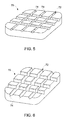
- the mechanical interlock pattern 72 is shown as simply a plurality of grooves 74, but it is to be appreciated that the mechanical interlock pattern 72 may be formed of a plurality of grooves, protrusions, or a combination thereof.
- the plurality of grooves 74 may take on a number of geometries including, but not limited to, grooves having a relatively "U" shape ( FIG. 5 ) or "V" shape ( FIG. 6 ), for example.
- the "U” and “V” shaped examples are merely illustrative of the various shapes that may be employed to form the plurality of grooves 74. Irrespective of the mechanical interlock pattern 72, and specifically the groove or protrusion arrangement, the arrangement provides an increased surface area for a hard face interface 80 to interlock with upon application, when compared to a merely flat surface.
- the substrate 70 is shown as providing an interface with the tip shroud 50 and the hard face interface 80.
- the substrate 70 provides retention and/or bonding function for the hard face interface 80 to the tip shroud 50.
- the hard face interface 80 is operably secured to the substrate 70 by welding or brazing, for example.
- the mechanical interlock pattern 72 of the substrate 70 increases the surface area available to form the securement of the hard face interface 80 to the substrate 70, thereby enhancing structural integrity.
- the hard face interface 80 includes a base portion 82 and a plurality of edge portions 84. It is contemplated that the substrate 70 may be secured to the hard face interface 80 at the base portion 82 or at least one of the plurality of edge portions 84, or a combination thereof.
- the substrate 70 provides additional structural integrity to the hard face interface 80 by partially or fully encapsulating one or more of the edge portions 84, such that the likelihood of damage to the hard face interface 80 due to a collision with other structures during operation, installation, or handling, is reduced.
- the hard face interface 80 may be formed of a pre-sintered preform (PSP) material, for example, but it is to be appreciated that various materials may be employed for differing applications of use.
- PSP pre-sintered preform
- the tip shroud 50 of FIG. 7 includes a single cutter member 90 disposed proximate a central location between the first edge 60 and the second edge 62 of the tip blade 52.
- the cutter member 90 extends away from both the first surface 56 and the second surface 58, such that regardless of the deformation of the tip shroud 50, or tip blade 52, during operation, the cutter member 90 may function to remove material from the aforementioned counterpart surface, such as a honeycomb structure.
- the substrate 70 is flared outward from the first surface 56 at a location proximate the second edge 62.
- an additional substrate portion may be flared outward at various other locations, such as away from the second surface 58 at a location proximate the first edge 60.
Landscapes
- Engineering & Computer Science (AREA)
- Mechanical Engineering (AREA)
- General Engineering & Computer Science (AREA)
- Turbine Rotor Nozzle Sealing (AREA)
- Structures Of Non-Positive Displacement Pumps (AREA)
Abstract
Description
- The subject matter disclosed herein relates to turbine systems, and more particularly to tip shrouds.
- Turbine systems employ a number of rotating components or assemblies, such as compressor stages and turbine stages that rotate at high speed when the turbine is in operation, for example. In general, a stage includes a plurality of free-floating blades that extend radially outward from a central hub. Some blades include a shroud that limits vibration within a stage. The shroud is typically positioned at a tip portion of the blade, a mid portion of the blade or at both the mid portion and the tip portion of the blade. The shrouds are designed such that at high or operational speeds, the free-floating blades interlock to form an integral rotating member, however, even at lower speeds and possibly even when starting from a starting position at 0 rpm, the blades may interlock. During blade interlock, wear occurs due to slip when the tip portions are interlocked. At lower speeds, such as on turbine turning gear, the blades may not interlock and will often times impact one another. Impacts between the blades can cause damage that will shorten service life of the turbomachine.
- In order to minimize damage resulting from blade impacts, a hard face coating is applied to potential contact points. The hard face coating increases wear resistance that may occur during operation of the blades and also increases the durability of potential contact points that may be susceptible to impacts. Conventionally, the hard face coating is metallurgically bonded to the blade through, for example, a welding, brazing or spraying process. Using a welding process to bond the hard face interface to the blade inherently produces a great deal of localized heat which, if not properly controlled, can weaken the wear and impact resistance and other metallurgical properties at the interface of the materials being joined. Excessive heat can also cause cracking in adjacent material during manufacture.
- According to one aspect of the invention, a rotating assembly for a turbine assembly includes an airfoil extending radially outward from, and rotatable about, an axial centerline. Also included is a tip shroud integrally connected proximate a radially outer tip of the airfoil. Further included is a substrate operably coupled to the tip shroud. Yet further included is at least one hard face interface member secured to the substrate.
- According to another aspect of the invention, a rotating assembly for a turbine assembly includes a plurality of rotating members extending radially outward from, and rotatable about, an axial centerline. Also included is a tip shroud integrally connected proximate a radially outer tip of at least one of the plurality of rotating members. Further included is a substrate operably coupled to the tip shroud. Yet further included is a hard face interface member having a base portion and a plurality of edge portions, wherein the base portion is secured to the substrate and a portion of the substrate at least partially surrounds at least one of the plurality of edge portions.
- According to yet another aspect of the invention, a rotating assembly for a turbine assembly includes an airfoil extending radially outward from, and rotatable about, an axial centerline. Also included is a tip shroud integrally connected proximate a radially outer tip of the airfoil. Further included is a substrate operably coupled to the tip shroud, wherein the substrate includes a plurality of grooved portions. Yet further included is at least one hard face interface member being both mechanically interlocked with, and metallurgically bonded to the substrate.
- These and other advantages and features will become more apparent from the following description taken in conjunction with the drawings.
- Embodiments of the present invention will now be described, by way of example only, with reference to the accompanying drawings in which:
-
FIG. 1 is a partial, cross-sectional schematic view of a turbomachine including a rotating assembly; -
FIG. 2 is a partial perspective view of a rotating assembly including a plurality of rotating components; -
FIG. 3 is a front perspective view of a tip shroud of a first embodiment; -
FIG. 4 is a rear, elevational view of the tip shroud ofFIG. 3 ; -
FIG. 5 is a perspective view of a substrate having a plurality of substantially "U" shaped grooves; -
FIG. 6 is a perspective view of a substrate having a plurality of "V" shaped grooves; and -
FIG. 7 is a front perspective view of a tip shroud of a second embodiment. - The detailed description explains embodiments of the invention, together with advantages and features, by way of example with reference to the drawings.
- Referring to
FIG. 1 , a turbomachine, shown in the form of a gas turbine engine, constructed in accordance with an exemplary embodiment of the present invention is indicated generally at 10. Theengine 10 includes acompressor 12 and a plurality of combustor assemblies arranged in a can annular array, one of which is indicated at 14. As shown, thecombustor assembly 14 includes anendcover assembly 16 that seals, and at least partially defines, acombustion chamber 18. A plurality of nozzles 20-22 are supported by theendcover assembly 16 and extend into thecombustion chamber 18. The nozzles 20-22 receive fuel through a common fuel inlet (not shown) and compressed air from thecompressor 12. The fuel and compressed air are passed into thecombustion chamber 18 and ignited to form a high temperature, high pressure combustion product or air stream that is used to drive aturbine 24. Theturbine 24 includes a plurality of rotating assemblies or stages 26-28 that are operationally connected to thecompressor 12 through a compressor/turbine shaft 30 (sometimes referred to as a rotor). - In operation, air flows into the
compressor 12 and is compressed into a high pressure gas. The high pressure gas is supplied to thecombustor assembly 14 and mixed with fuel, for example process gas and/or synthetic gas (syngas), in thecombustion chamber 18. The fuel/air or combustible mixture ignite to form a high pressure, high temperature combustion gas stream of approximately 538 degrees Celsius (°C) to 1593 °C (1000 degrees Fahrenheit (°F) to 2900 °F). Alternatively, thecombustor assembly 14 can combust fuels that include, but are not limited to, natural gas and/or fuel oil. In any event, thecombustor assembly 14 channels the combustion gas stream to theturbine 24 which converts thermal energy to mechanical, rotational energy. - At this point, it should be understood that each rotating assembly or stage 26-28 is similarly formed, thus reference will be made to
FIG. 2 in describingstage 26 constructed in accordance with an exemplary embodiment of the present invention with an understanding that the remaining stages, i.e.,stages compressor 12 or other rotating assemblies that require wear and/or impact resistant surfaces. In any event, thestage 26 is shown to include a plurality of rotating members, such as anairfoil 32, which each extend radially outward from a central hub 34 having an axial centerline 35. Theairfoil 32 is rotatable about the axial centerline 35 of the central hub 34 and includes abase portion 36 and atip portion 38. - The
tip shroud 50 covers a bucket or throat portion (not separately labeled) ofairfoil 32. Thetip shroud 50 is designed to receive, or nest with, tip shrouds on adjacent rotating members in order to form a continuous ring that extends circumferentially about thestage 26. The continuous ring creates an outer flow path boundary that reduces gas path air leakage over top portions (not separately labeled) of thestage 26, so as to increase stage efficiency and overall turbine performance. In the exemplary embodiment shown, during high or operational speeds,adjacent airfoils 32 interlock through their respective tip-shrouds 50 by virtue of centrifugal forces created by the operation of theturbine 24. It should be noted that interlock may occur even at extremely low speed operation, such that wearing due to slipping of the blades may occur due to operation during interlock. However, during lower speeds such as, during turbine turning gear, the rotational force may not be sufficient to establish the interlock and thus, adjacent rotating members may impact one another. The impacts can create wear on the rotating members thereby lowering an overall service life of theturbine 24. Additionally, operator handling at several manufacturing and assembly stages may result in such impacts. Towards that end,tip shroud 50 is provided with a wear resistant/impact resistant member in a manner that will be described more fully below. - Referring to
FIGS. 3 and 4 , thetip shroud 50 includes atip blade 52 that extends generally along atop surface 54 of thetip shroud 50. Thetip blade 52 is comprised of afirst surface 56 and an opposingsecond surface 58, as well as afirst edge 60 and asecond edge 62. In the exemplary embodiment illustrated, thetip blade 52 also includes one or more cutter members, such as afirst cutter member 64 and asecond cutter member 66. Thefirst cutter member 64 is disposed proximate thefirst edge 60 of thetip blade 52 and on thesecond surface 58, while thesecond cutter member 66 is disposed proximate thesecond edge 62 and on thefirst surface 56. Both the first andsecond cutter members second cutter members stage 26. - Referring to
FIGS. 5 and 6 , asubstrate 70 is operably coupled to thetip shroud 50 and includes amechanical interlock pattern 72. In the illustrated embodiments, themechanical interlock pattern 72 is shown as simply a plurality ofgrooves 74, but it is to be appreciated that themechanical interlock pattern 72 may be formed of a plurality of grooves, protrusions, or a combination thereof. The plurality ofgrooves 74 may take on a number of geometries including, but not limited to, grooves having a relatively "U" shape (FIG. 5 ) or "V" shape (FIG. 6 ), for example. The "U" and "V" shaped examples are merely illustrative of the various shapes that may be employed to form the plurality ofgrooves 74. Irrespective of themechanical interlock pattern 72, and specifically the groove or protrusion arrangement, the arrangement provides an increased surface area for ahard face interface 80 to interlock with upon application, when compared to a merely flat surface. - Referring again to
FIGS. 3 and 4 , thesubstrate 70 is shown as providing an interface with thetip shroud 50 and thehard face interface 80. Thesubstrate 70 provides retention and/or bonding function for thehard face interface 80 to thetip shroud 50. Thehard face interface 80 is operably secured to thesubstrate 70 by welding or brazing, for example. As previously described, themechanical interlock pattern 72 of thesubstrate 70 increases the surface area available to form the securement of thehard face interface 80 to thesubstrate 70, thereby enhancing structural integrity. Thehard face interface 80 includes abase portion 82 and a plurality ofedge portions 84. It is contemplated that thesubstrate 70 may be secured to thehard face interface 80 at thebase portion 82 or at least one of the plurality ofedge portions 84, or a combination thereof. Thesubstrate 70 provides additional structural integrity to thehard face interface 80 by partially or fully encapsulating one or more of theedge portions 84, such that the likelihood of damage to thehard face interface 80 due to a collision with other structures during operation, installation, or handling, is reduced. Thehard face interface 80 may be formed of a pre-sintered preform (PSP) material, for example, but it is to be appreciated that various materials may be employed for differing applications of use. - Referring to
FIG. 7 , atip shroud 50 similar to that illustrated inFIGS. 3 and 4 is shown. Thetip shroud 50 ofFIG. 7 includes asingle cutter member 90 disposed proximate a central location between thefirst edge 60 and thesecond edge 62 of thetip blade 52. Thecutter member 90 extends away from both thefirst surface 56 and thesecond surface 58, such that regardless of the deformation of thetip shroud 50, ortip blade 52, during operation, thecutter member 90 may function to remove material from the aforementioned counterpart surface, such as a honeycomb structure. In the illustrated embodiment, thesubstrate 70 is flared outward from thefirst surface 56 at a location proximate thesecond edge 62. Similarly, an additional substrate portion may be flared outward at various other locations, such as away from thesecond surface 58 at a location proximate thefirst edge 60. - While the invention has been described in detail in connection with only a limited number of embodiments, it should be readily understood that the invention is not limited to such disclosed embodiments. Rather, the invention can be modified to incorporate any number of variations, alterations, substitutions or equivalent arrangements not heretofore described, but which are commensurate with the spirit and scope of the invention. Additionally, while various embodiments of the invention have been described, it is to be understood that aspects of the invention may include only some of the described embodiments. Accordingly, the invention is not to be seen as limited by the foregoing description, but is only limited by the scope of the appended claims.
Claims (11)
- A rotating assembly (26-28) for a turbine assembly comprising:an airfoil (32) extending radially outward from, and rotatable about, an axial centerline (35);a tip shroud (50) integrally connected proximate a radially outer tip (38)of the airfoil (32);a substrate (70) operably coupled to the tip shroud (50); andat least one hard face interface member (80) secured to the substrate (70).
- The rotating assembly of claim 1, the tip shroud (50) comprising:a tip blade (52) having a first surface (56), a second surface (58) opposing the first surface (56), a first edge (60) and a second edge (62),a first cutter member (64) disposed proximate the first edge (60) and the second surface (58); anda second cutter member (66) disposed proximate the second edge (62) and the first surface (56).
- The rotating assembly of claim 1 or 2, the tip shroud (50) comprising a relatively planar tip blade (52) having a first edge (60) and a second edge (62), wherein the substrate includes a fillet portion proximate at least one of the first edge (60) or the second edge (62).
- The rotating assembly of any of claims 1 to 3, wherein the at least one hard face interface (80) member includes a base portion (82) and a plurality of edge portions (84), wherein a portion of the substrate (70) at least partially surrounds at least one of the plurality of edge portions (84).
- The rotating assembly of any of claims 1 to 4, wherein the at least one hard face interface member (80) is formed from a pre-sintered preformed material.
- The rotating assembly of any preceding claim
wherein the at least one hard face interface member (80) is both mechanically interlocked with, and metallurgically bonded to the substrate (70). - The rotating assembly of any preceding claim, wherein the substrate (70) includes a plurality of grooved portions (74).
- The rotating assembly of claim 7, wherein the plurality of grooved portions are (74) relatively U-shaped.
- The rotating assembly of claim 7, wherein the plurality of grooved portions (74) are relatively V-shaped.
- The rotating assembly of any preceding claim, wherein the substrate (70) includes a plurality of protrusions.
- The rotating assembly of any preceding claim, wherein the at least one hard face interface member (80) is brazed to the substrate (70).
Applications Claiming Priority (1)
| Application Number | Priority Date | Filing Date | Title |
|---|---|---|---|
| US13/368,931 US20130202439A1 (en) | 2012-02-08 | 2012-02-08 | Rotating assembly for a turbine assembly |
Publications (3)
| Publication Number | Publication Date |
|---|---|
| EP2626517A2 true EP2626517A2 (en) | 2013-08-14 |
| EP2626517A3 EP2626517A3 (en) | 2017-03-29 |
| EP2626517B1 EP2626517B1 (en) | 2020-04-01 |
Family
ID=47709946
Family Applications (1)
| Application Number | Title | Priority Date | Filing Date |
|---|---|---|---|
| EP13154014.8A Not-in-force EP2626517B1 (en) | 2012-02-08 | 2013-02-05 | Rotating assembly for a turbine assembly |
Country Status (3)
| Country | Link |
|---|---|
| US (1) | US20130202439A1 (en) |
| EP (1) | EP2626517B1 (en) |
| JP (1) | JP6239237B2 (en) |
Cited By (1)
| Publication number | Priority date | Publication date | Assignee | Title |
|---|---|---|---|---|
| EP3699399A1 (en) * | 2019-02-21 | 2020-08-26 | MTU Aero Engines GmbH | Blade for a high-speed turbine stage with single sealing element |
Families Citing this family (6)
| Publication number | Priority date | Publication date | Assignee | Title |
|---|---|---|---|---|
| JP6567394B2 (en) * | 2015-11-10 | 2019-08-28 | 株式会社東芝 | Method for repairing worn parts of gas turbine parts |
| WO2017155497A1 (en) * | 2016-03-07 | 2017-09-14 | Siemens Aktiengesellschaft | Gas turbine blade tip shroud sealing and flow guiding features |
| US10830082B2 (en) * | 2017-05-10 | 2020-11-10 | General Electric Company | Systems including rotor blade tips and circumferentially grooved shrouds |
| US12123319B2 (en) | 2020-12-30 | 2024-10-22 | Ge Infrastructure Technology Llc | Cooling circuit having a bypass conduit for a turbomachine component |
| FR3161707A1 (en) * | 2024-04-30 | 2025-10-31 | Safran Aircraft Engines | DAWN EQUIPPED WITH A VISUAL WEAR INDICATOR |
| FR3165926A1 (en) * | 2024-09-05 | 2026-03-06 | Safran Aircraft Engines | ROTOR BLADE FOR A TURBOMACHINE |
Family Cites Families (10)
| Publication number | Priority date | Publication date | Assignee | Title |
|---|---|---|---|---|
| US4764089A (en) * | 1986-08-07 | 1988-08-16 | Allied-Signal Inc. | Abradable strain-tolerant ceramic coated turbine shroud |
| US6224963B1 (en) * | 1997-05-14 | 2001-05-01 | Alliedsignal Inc. | Laser segmented thick thermal barrier coatings for turbine shrouds |
| US6164916A (en) * | 1998-11-02 | 2000-12-26 | General Electric Company | Method of applying wear-resistant materials to turbine blades, and turbine blades having wear-resistant materials |
| US7001152B2 (en) * | 2003-10-09 | 2006-02-21 | Pratt & Wiley Canada Corp. | Shrouded turbine blades with locally increased contact faces |
| US7094032B2 (en) * | 2004-02-26 | 2006-08-22 | Richard Seleski | Turbine blade shroud cutter tip |
| US7686568B2 (en) * | 2006-09-22 | 2010-03-30 | General Electric Company | Methods and apparatus for fabricating turbine engines |
| US7771171B2 (en) * | 2006-12-14 | 2010-08-10 | General Electric Company | Systems for preventing wear on turbine blade tip shrouds |
| US9009965B2 (en) * | 2007-05-24 | 2015-04-21 | General Electric Company | Method to center locate cutter teeth on shrouded turbine blades |
| US20090202344A1 (en) * | 2008-02-13 | 2009-08-13 | General Electric Company | Rotating assembly for a turbomachine |
| EP2456957B1 (en) * | 2009-07-22 | 2016-05-04 | MTU Aero Engines GmbH | Method for coating of turbine blades |
-
2012
- 2012-02-08 US US13/368,931 patent/US20130202439A1/en not_active Abandoned
-
2013
- 2013-01-31 JP JP2013016279A patent/JP6239237B2/en not_active Expired - Fee Related
- 2013-02-05 EP EP13154014.8A patent/EP2626517B1/en not_active Not-in-force
Non-Patent Citations (1)
| Title |
|---|
| None |
Cited By (2)
| Publication number | Priority date | Publication date | Assignee | Title |
|---|---|---|---|---|
| EP3699399A1 (en) * | 2019-02-21 | 2020-08-26 | MTU Aero Engines GmbH | Blade for a high-speed turbine stage with single sealing element |
| US11230933B2 (en) | 2019-02-21 | 2022-01-25 | MTU Aero Engines AG | Blade for a high-speed turbine stage having a single sealing element |
Also Published As
| Publication number | Publication date |
|---|---|
| EP2626517A3 (en) | 2017-03-29 |
| US20130202439A1 (en) | 2013-08-08 |
| EP2626517B1 (en) | 2020-04-01 |
| JP6239237B2 (en) | 2017-11-29 |
| JP2013160228A (en) | 2013-08-19 |
Similar Documents
| Publication | Publication Date | Title |
|---|---|---|
| EP2626517B1 (en) | Rotating assembly for a turbine assembly | |
| US8376697B2 (en) | Gas turbine sealing apparatus | |
| CN103306749B (en) | For the black box of rotating machinery and for assembling the method for rotating machinery | |
| CN104806299B (en) | Turbine bucket leaf with double partial-span shields and bending dovetail | |
| JP6143523B2 (en) | Turbine shroud assembly and method of forming the same | |
| US9822659B2 (en) | Gas turbine with honeycomb seal | |
| US20120034101A1 (en) | Turbine blade squealer tip | |
| US20160010560A1 (en) | Sealing features for a gas turbine engine | |
| EP3219910B1 (en) | Disc for a rotor of a gas turbine engine, and a rotor and a gas turbine comprising the same | |
| US20130028741A1 (en) | Cap for ceramic blade tip shroud | |
| JP2002309902A (en) | Method of reducing seal tooth wear, honeycomb seal and gas turbine engine | |
| JP2009024698A (en) | Pressing plate seal | |
| US20090202355A1 (en) | Replaceable blade tip shroud | |
| EP2090748A2 (en) | Shroud assembly for a turbomachine | |
| CN104471192A (en) | Damper system and corresponding turbine | |
| CN105026692A (en) | Turbine blade pin seal | |
| US9175573B2 (en) | Dovetail attachment seal for a turbomachine | |
| US20140112753A1 (en) | Sealing arrangement for a turbine system and method of sealing between two turbine components | |
| EP3219912A1 (en) | Dual snapped cover plate with retention ring attachment | |
| EP3673153B1 (en) | Rim seal arrangement | |
| US10329929B2 (en) | Retaining ring axially loaded against segmented disc surface | |
| CN110662884A (en) | Turbine blades with grooved tips and dense oxide dispersion strengthened layers | |
| EP3219908B1 (en) | Disc for a rotor assembly of a gas turbine, rotor assembly, and gas turbine | |
| US20190376392A1 (en) | Gas turbine |
Legal Events
| Date | Code | Title | Description |
|---|---|---|---|
| PUAI | Public reference made under article 153(3) epc to a published international application that has entered the european phase |
Free format text: ORIGINAL CODE: 0009012 |
|
| AK | Designated contracting states |
Kind code of ref document: A2 Designated state(s): AL AT BE BG CH CY CZ DE DK EE ES FI FR GB GR HR HU IE IS IT LI LT LU LV MC MK MT NL NO PL PT RO RS SE SI SK SM TR |
|
| AX | Request for extension of the european patent |
Extension state: BA ME |
|
| PUAL | Search report despatched |
Free format text: ORIGINAL CODE: 0009013 |
|
| AK | Designated contracting states |
Kind code of ref document: A3 Designated state(s): AL AT BE BG CH CY CZ DE DK EE ES FI FR GB GR HR HU IE IS IT LI LT LU LV MC MK MT NL NO PL PT RO RS SE SI SK SM TR |
|
| AX | Request for extension of the european patent |
Extension state: BA ME |
|
| RIC1 | Information provided on ipc code assigned before grant |
Ipc: F01D 11/08 20060101ALI20170223BHEP Ipc: F01D 5/22 20060101AFI20170223BHEP Ipc: F01D 5/30 20060101ALN20170223BHEP Ipc: F01D 11/12 20060101ALI20170223BHEP |
|
| STAA | Information on the status of an ep patent application or granted ep patent |
Free format text: STATUS: REQUEST FOR EXAMINATION WAS MADE |
|
| 17P | Request for examination filed |
Effective date: 20170929 |
|
| RBV | Designated contracting states (corrected) |
Designated state(s): AL AT BE BG CH CY CZ DE DK EE ES FI FR GB GR HR HU IE IS IT LI LT LU LV MC MK MT NL NO PL PT RO RS SE SI SK SM TR |
|
| STAA | Information on the status of an ep patent application or granted ep patent |
Free format text: STATUS: EXAMINATION IS IN PROGRESS |
|
| 17Q | First examination report despatched |
Effective date: 20190322 |
|
| RIC1 | Information provided on ipc code assigned before grant |
Ipc: F01D 5/22 20060101AFI20190807BHEP Ipc: F01D 11/08 20060101ALI20190807BHEP Ipc: F01D 5/30 20060101ALN20190807BHEP Ipc: F01D 11/12 20060101ALI20190807BHEP |
|
| GRAP | Despatch of communication of intention to grant a patent |
Free format text: ORIGINAL CODE: EPIDOSNIGR1 |
|
| STAA | Information on the status of an ep patent application or granted ep patent |
Free format text: STATUS: GRANT OF PATENT IS INTENDED |
|
| RIC1 | Information provided on ipc code assigned before grant |
Ipc: F01D 5/30 20060101ALN20190823BHEP Ipc: F01D 11/08 20060101ALI20190823BHEP Ipc: F01D 5/22 20060101AFI20190823BHEP Ipc: F01D 11/12 20060101ALI20190823BHEP |
|
| INTG | Intention to grant announced |
Effective date: 20190916 |
|
| GRAS | Grant fee paid |
Free format text: ORIGINAL CODE: EPIDOSNIGR3 |
|
| GRAA | (expected) grant |
Free format text: ORIGINAL CODE: 0009210 |
|
| STAA | Information on the status of an ep patent application or granted ep patent |
Free format text: STATUS: THE PATENT HAS BEEN GRANTED |
|
| AK | Designated contracting states |
Kind code of ref document: B1 Designated state(s): AL AT BE BG CH CY CZ DE DK EE ES FI FR GB GR HR HU IE IS IT LI LT LU LV MC MK MT NL NO PL PT RO RS SE SI SK SM TR |
|
| REG | Reference to a national code |
Ref country code: GB Ref legal event code: FG4D |
|
| REG | Reference to a national code |
Ref country code: AT Ref legal event code: REF Ref document number: 1251572 Country of ref document: AT Kind code of ref document: T Effective date: 20200415 Ref country code: CH Ref legal event code: EP |
|
| REG | Reference to a national code |
Ref country code: DE Ref legal event code: R096 Ref document number: 602013067353 Country of ref document: DE |
|
| REG | Reference to a national code |
Ref country code: IE Ref legal event code: FG4D |
|
| PG25 | Lapsed in a contracting state [announced via postgrant information from national office to epo] |
Ref country code: BG Free format text: LAPSE BECAUSE OF FAILURE TO SUBMIT A TRANSLATION OF THE DESCRIPTION OR TO PAY THE FEE WITHIN THE PRESCRIBED TIME-LIMIT Effective date: 20200701 |
|
| REG | Reference to a national code |
Ref country code: NL Ref legal event code: MP Effective date: 20200401 |
|
| REG | Reference to a national code |
Ref country code: LT Ref legal event code: MG4D |
|
| PG25 | Lapsed in a contracting state [announced via postgrant information from national office to epo] |
Ref country code: NO Free format text: LAPSE BECAUSE OF FAILURE TO SUBMIT A TRANSLATION OF THE DESCRIPTION OR TO PAY THE FEE WITHIN THE PRESCRIBED TIME-LIMIT Effective date: 20200701 Ref country code: SE Free format text: LAPSE BECAUSE OF FAILURE TO SUBMIT A TRANSLATION OF THE DESCRIPTION OR TO PAY THE FEE WITHIN THE PRESCRIBED TIME-LIMIT Effective date: 20200401 Ref country code: IS Free format text: LAPSE BECAUSE OF FAILURE TO SUBMIT A TRANSLATION OF THE DESCRIPTION OR TO PAY THE FEE WITHIN THE PRESCRIBED TIME-LIMIT Effective date: 20200801 Ref country code: NL Free format text: LAPSE BECAUSE OF FAILURE TO SUBMIT A TRANSLATION OF THE DESCRIPTION OR TO PAY THE FEE WITHIN THE PRESCRIBED TIME-LIMIT Effective date: 20200401 Ref country code: CZ Free format text: LAPSE BECAUSE OF FAILURE TO SUBMIT A TRANSLATION OF THE DESCRIPTION OR TO PAY THE FEE WITHIN THE PRESCRIBED TIME-LIMIT Effective date: 20200401 Ref country code: PT Free format text: LAPSE BECAUSE OF FAILURE TO SUBMIT A TRANSLATION OF THE DESCRIPTION OR TO PAY THE FEE WITHIN THE PRESCRIBED TIME-LIMIT Effective date: 20200817 Ref country code: LT Free format text: LAPSE BECAUSE OF FAILURE TO SUBMIT A TRANSLATION OF THE DESCRIPTION OR TO PAY THE FEE WITHIN THE PRESCRIBED TIME-LIMIT Effective date: 20200401 Ref country code: FI Free format text: LAPSE BECAUSE OF FAILURE TO SUBMIT A TRANSLATION OF THE DESCRIPTION OR TO PAY THE FEE WITHIN THE PRESCRIBED TIME-LIMIT Effective date: 20200401 Ref country code: GR Free format text: LAPSE BECAUSE OF FAILURE TO SUBMIT A TRANSLATION OF THE DESCRIPTION OR TO PAY THE FEE WITHIN THE PRESCRIBED TIME-LIMIT Effective date: 20200702 |
|
| REG | Reference to a national code |
Ref country code: AT Ref legal event code: MK05 Ref document number: 1251572 Country of ref document: AT Kind code of ref document: T Effective date: 20200401 |
|
| PG25 | Lapsed in a contracting state [announced via postgrant information from national office to epo] |
Ref country code: LV Free format text: LAPSE BECAUSE OF FAILURE TO SUBMIT A TRANSLATION OF THE DESCRIPTION OR TO PAY THE FEE WITHIN THE PRESCRIBED TIME-LIMIT Effective date: 20200401 Ref country code: HR Free format text: LAPSE BECAUSE OF FAILURE TO SUBMIT A TRANSLATION OF THE DESCRIPTION OR TO PAY THE FEE WITHIN THE PRESCRIBED TIME-LIMIT Effective date: 20200401 Ref country code: RS Free format text: LAPSE BECAUSE OF FAILURE TO SUBMIT A TRANSLATION OF THE DESCRIPTION OR TO PAY THE FEE WITHIN THE PRESCRIBED TIME-LIMIT Effective date: 20200401 |
|
| PG25 | Lapsed in a contracting state [announced via postgrant information from national office to epo] |
Ref country code: AL Free format text: LAPSE BECAUSE OF FAILURE TO SUBMIT A TRANSLATION OF THE DESCRIPTION OR TO PAY THE FEE WITHIN THE PRESCRIBED TIME-LIMIT Effective date: 20200401 |
|
| REG | Reference to a national code |
Ref country code: DE Ref legal event code: R097 Ref document number: 602013067353 Country of ref document: DE |
|
| PG25 | Lapsed in a contracting state [announced via postgrant information from national office to epo] |
Ref country code: IT Free format text: LAPSE BECAUSE OF FAILURE TO SUBMIT A TRANSLATION OF THE DESCRIPTION OR TO PAY THE FEE WITHIN THE PRESCRIBED TIME-LIMIT Effective date: 20200401 Ref country code: SM Free format text: LAPSE BECAUSE OF FAILURE TO SUBMIT A TRANSLATION OF THE DESCRIPTION OR TO PAY THE FEE WITHIN THE PRESCRIBED TIME-LIMIT Effective date: 20200401 Ref country code: RO Free format text: LAPSE BECAUSE OF FAILURE TO SUBMIT A TRANSLATION OF THE DESCRIPTION OR TO PAY THE FEE WITHIN THE PRESCRIBED TIME-LIMIT Effective date: 20200401 Ref country code: EE Free format text: LAPSE BECAUSE OF FAILURE TO SUBMIT A TRANSLATION OF THE DESCRIPTION OR TO PAY THE FEE WITHIN THE PRESCRIBED TIME-LIMIT Effective date: 20200401 Ref country code: AT Free format text: LAPSE BECAUSE OF FAILURE TO SUBMIT A TRANSLATION OF THE DESCRIPTION OR TO PAY THE FEE WITHIN THE PRESCRIBED TIME-LIMIT Effective date: 20200401 Ref country code: DK Free format text: LAPSE BECAUSE OF FAILURE TO SUBMIT A TRANSLATION OF THE DESCRIPTION OR TO PAY THE FEE WITHIN THE PRESCRIBED TIME-LIMIT Effective date: 20200401 Ref country code: ES Free format text: LAPSE BECAUSE OF FAILURE TO SUBMIT A TRANSLATION OF THE DESCRIPTION OR TO PAY THE FEE WITHIN THE PRESCRIBED TIME-LIMIT Effective date: 20200401 |
|
| PLBE | No opposition filed within time limit |
Free format text: ORIGINAL CODE: 0009261 |
|
| STAA | Information on the status of an ep patent application or granted ep patent |
Free format text: STATUS: NO OPPOSITION FILED WITHIN TIME LIMIT |
|
| PG25 | Lapsed in a contracting state [announced via postgrant information from national office to epo] |
Ref country code: PL Free format text: LAPSE BECAUSE OF FAILURE TO SUBMIT A TRANSLATION OF THE DESCRIPTION OR TO PAY THE FEE WITHIN THE PRESCRIBED TIME-LIMIT Effective date: 20200401 Ref country code: SK Free format text: LAPSE BECAUSE OF FAILURE TO SUBMIT A TRANSLATION OF THE DESCRIPTION OR TO PAY THE FEE WITHIN THE PRESCRIBED TIME-LIMIT Effective date: 20200401 |
|
| 26N | No opposition filed |
Effective date: 20210112 |
|
| PG25 | Lapsed in a contracting state [announced via postgrant information from national office to epo] |
Ref country code: SI Free format text: LAPSE BECAUSE OF FAILURE TO SUBMIT A TRANSLATION OF THE DESCRIPTION OR TO PAY THE FEE WITHIN THE PRESCRIBED TIME-LIMIT Effective date: 20200401 |
|
| REG | Reference to a national code |
Ref country code: DE Ref legal event code: R119 Ref document number: 602013067353 Country of ref document: DE |
|
| PG25 | Lapsed in a contracting state [announced via postgrant information from national office to epo] |
Ref country code: MC Free format text: LAPSE BECAUSE OF FAILURE TO SUBMIT A TRANSLATION OF THE DESCRIPTION OR TO PAY THE FEE WITHIN THE PRESCRIBED TIME-LIMIT Effective date: 20200401 |
|
| GBPC | Gb: european patent ceased through non-payment of renewal fee |
Effective date: 20210205 |
|
| REG | Reference to a national code |
Ref country code: BE Ref legal event code: MM Effective date: 20210228 |
|
| PG25 | Lapsed in a contracting state [announced via postgrant information from national office to epo] |
Ref country code: LU Free format text: LAPSE BECAUSE OF NON-PAYMENT OF DUE FEES Effective date: 20210205 Ref country code: LI Free format text: LAPSE BECAUSE OF NON-PAYMENT OF DUE FEES Effective date: 20210228 Ref country code: CH Free format text: LAPSE BECAUSE OF NON-PAYMENT OF DUE FEES Effective date: 20210228 |
|
| PG25 | Lapsed in a contracting state [announced via postgrant information from national office to epo] |
Ref country code: DE Free format text: LAPSE BECAUSE OF NON-PAYMENT OF DUE FEES Effective date: 20210901 Ref country code: FR Free format text: LAPSE BECAUSE OF NON-PAYMENT OF DUE FEES Effective date: 20210228 Ref country code: IE Free format text: LAPSE BECAUSE OF NON-PAYMENT OF DUE FEES Effective date: 20210205 Ref country code: GB Free format text: LAPSE BECAUSE OF NON-PAYMENT OF DUE FEES Effective date: 20210205 |
|
| PG25 | Lapsed in a contracting state [announced via postgrant information from national office to epo] |
Ref country code: BE Free format text: LAPSE BECAUSE OF NON-PAYMENT OF DUE FEES Effective date: 20210228 |
|
| PG25 | Lapsed in a contracting state [announced via postgrant information from national office to epo] |
Ref country code: HU Free format text: LAPSE BECAUSE OF FAILURE TO SUBMIT A TRANSLATION OF THE DESCRIPTION OR TO PAY THE FEE WITHIN THE PRESCRIBED TIME-LIMIT; INVALID AB INITIO Effective date: 20130205 |
|
| PG25 | Lapsed in a contracting state [announced via postgrant information from national office to epo] |
Ref country code: CY Free format text: LAPSE BECAUSE OF FAILURE TO SUBMIT A TRANSLATION OF THE DESCRIPTION OR TO PAY THE FEE WITHIN THE PRESCRIBED TIME-LIMIT Effective date: 20200401 |
|
| PG25 | Lapsed in a contracting state [announced via postgrant information from national office to epo] |
Ref country code: MK Free format text: LAPSE BECAUSE OF FAILURE TO SUBMIT A TRANSLATION OF THE DESCRIPTION OR TO PAY THE FEE WITHIN THE PRESCRIBED TIME-LIMIT Effective date: 20200401 |
|
| PG25 | Lapsed in a contracting state [announced via postgrant information from national office to epo] |
Ref country code: TR Free format text: LAPSE BECAUSE OF FAILURE TO SUBMIT A TRANSLATION OF THE DESCRIPTION OR TO PAY THE FEE WITHIN THE PRESCRIBED TIME-LIMIT Effective date: 20200401 |
|
| PG25 | Lapsed in a contracting state [announced via postgrant information from national office to epo] |
Ref country code: MT Free format text: LAPSE BECAUSE OF FAILURE TO SUBMIT A TRANSLATION OF THE DESCRIPTION OR TO PAY THE FEE WITHIN THE PRESCRIBED TIME-LIMIT Effective date: 20200401 |